

Page 1
PNEG-1797
CE Approved T-Series
Tower Dryer
Operation Manual
PNEG-1797
Date: 06-11-12
Page 2

2 PNEG-1797CE CE Approved T-Series Tower Dryer
Page 3
PNEG-1797CE CE Approved T-Series Tower Dryer 3
Page 4
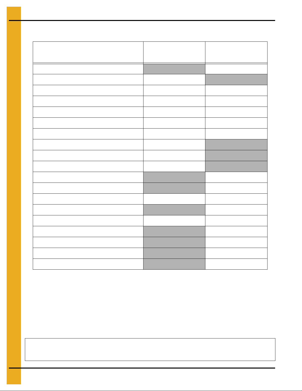
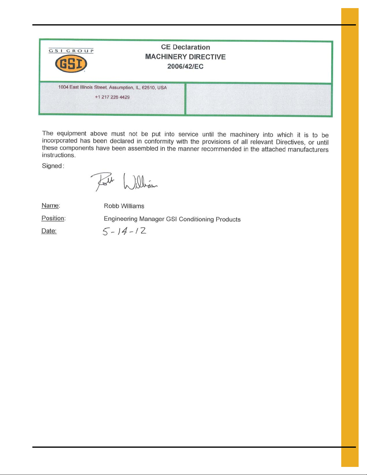
Tower Dryer Gas Train Commissioning Check List and Sign-Off
Name: _______________________Signed: _______________________ Date: ____________
All information, illustrations, photos and specifications in this manual are based on the latest
information available at the time of publication. The right is reserved to make changes at any
time without notice.
Function
Component Set Point
Pass/Fail/NA
Check Fuel Supply Shut Off Valve
Check Main Fuel Supply Pressure
Set/Test Main Gas Regulator Pressure
Set/Test Over Pressure Shut Off (OPSO) Pressure
Set/Test Pressure Relief V a lve
Set/Test Maximum Gas Pressure Switch
Set/Test Minimum Gas Pressure Switch
Set Pilot Burner Pressure
Set Burner High Flame Pressure
Set Burner Low Flame Pressure
Test Pilot Line Manual Shut Off Valve
Test Main Gas Manual Shut Off Valve
Set/Test Plenum High-Limit
Carry Out Leak Test
Check Purge Time
Check Pilot Ignition
Check Main Flame Ignition
Check Modulating Valve Operation
Check Burner Shut Down
4 PNEG-1797CE CE Approved T-Series Tower Dryer
Page 5

Table of Contents
Contents
Chapter 1 Safety .....................................................................................................................................................7
Safety Guidelines .................................................................................................................................. 7
Tower Dryer Operations and Service .................................................................................................... 8
Safety Precautions .............................................. ... ... .... ... ... ... .... ... ........................................................ 8
Working at Heights ................................................................................................................................ 9
Entering Grain Dryers ............................ ... ... ....................................................................................... 10
Precautions to Reduce Risk of Fire ..................................................................................................... 12
Chapter 2 Decals ..................................................................................................................................................13
Chapter 3 Specifications .....................................................................................................................................20
Electrical .................................... ................ ................ ................. ................ ......................................... 20
Fuel ..................................................................................................................................................... 21
Dimensions ......................................................................................................................................... 23
Chapter 4 Dryer Installation ................................................................................................................................26
Dryer Layout ........................................................................................................................................ 26
Foundation .......................................................................................................................................... 26
Standard Base for Models 1050, 1260, 1575, 1875 and 20100 .......................................................... 27
Standard Base for Model 24100 ......................................................................................................... 28
Fuel Connections ................................................................................................................................ 29
Electrical Connection .......................................................................................................................... 29
Connecting Auxiliary Conveyors ......................................................................................................... 29
Chapter 5 Operating Controls .............................................................................................................................30
Vision Control Panel Layout ................................................................................................................ 30
Chapter 6 Vision Touch Screen Display ........................................................................... .... .............................32
Select Data Log Sample Time ............................................................................................................ 33
Optional Operation Screen ............... ... ... ... ... .... ... ... ... .... ... .......................................... ... ...................... 34
Setting the Timers ............................................................................................................................... 35
Setting the Temperatures .................................................................................................................... 36
The Setup Screen ............................................................................................................................... 37
Viewing the Owner’s Manuals on the Display Screen ......................................................................... 40
Viewing the Dryer Shut Down History ................................................................................................. 41
Chapter 7 Dryer Start-Up .....................................................................................................................................42
Dryer Commissioning .......................................................................................................................... 42
Pre-Season Checks ............................................................................................................................ 46
Chapter 8 Dryer Start-Up and Operation ...........................................................................................................53
Drying Temperatures .......................... ... ... ... .......................................... .... ... ... ... .... ............................ 53
Initial Setup Parameters ............................ ............................................. ............................................. 53
Start-Up .................................. ............................................. ................................................................ 53
Continuous Flow Drying Mode Using Advanced Moisture Control ..................................... .... ... ... ... ... 54
How the Advanced Moisture Control Works ....................................................................................... 58
Chapter 9 Drying Time Tables ............................................................................................................................59
Chapter 10 Service ...............................................................................................................................................65
Pre-Seasonal Inspection and Service ..................... .... ... ... ... .......................................... ... .... ... ... ...... 65
Seasonal Inspection and Service ...................................................................................................... 65
In Case of Fire ................................................................................................................................... 66
End of Season Service ...................................................................................................................... 66
Pre-Season Service Check List ......................................................................................................... 67
End of Season Shut Down Procedure ............................... ... .... ... ... ... ... .... ... ... ................................... 67
Chapter 11 Lubrication ........................................................................................................................................68
PNEG-1797CE CE Approved T-Series Tower Dryer 5
Page 6

Table of Contents
Chapter 12 Error Messages ................................................................................................................................69
Safety Circuit Shut Down Messages ................................................................................................. 69
Input/Output Generated Errors .......................................................................................................... 70
Master Display Generated Errors ...................................................................................................... 71
Chapter 13 Wiring Diagrams for Pactrol Burner Control .................................................................................72
Upper Terminal Strip Wiring .............................................................................................................. 72
Burner/Fan Control Wiring ................................................................................................................. 73
Lower Terminal Strip Wiring .............................................................................................................. 74
Safety Relay Wiring ........................................................................................................................... 75
Upper Terminal Strip Field Connections ............................................................................................ 76
Lower Terminal Strip Field Connections ............................................................................................ 77
Chapter 14 Wiring Diagrams for Honeywell Burner Control ............................................................................78
Upper Terminal Strip Wiring .............................................................................................................. 78
Burner/Fan Control Wiring ................................................................................................................. 79
Lower Terminal Strip Wiring .............................................................................................................. 80
Safety Relay Wiring ........................................................................................................................... 81
Upper Terminal Strip Field Connections ............................................................................................ 82
Lower Terminal Strip Field Connections ............................................................................................ 83
Chapter 15 Warranty ............................................................................................................................................85
6 PNEG-1797CE CE Approved T-Series Tower Dryer
Page 7
1. Safety
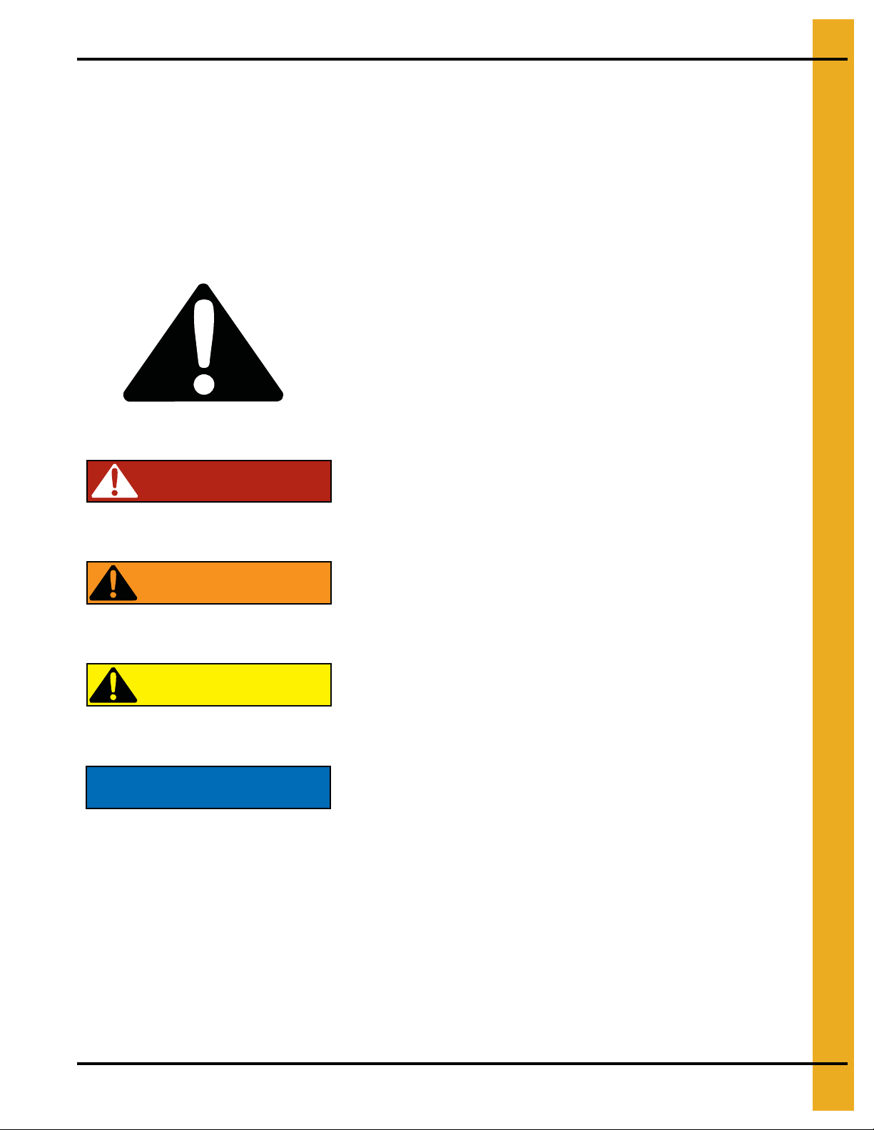
DANGER
WARNING
CAUTION
NOTICE
This is the safety alert symbol. It is used to alert you
to potential personal injury hazards. Obey all safety
messages that follow this symbol to avoid possible
injury or death.
WARNING indicates a hazardous situation which, if not
avoided, could result in death or serious injury.
CAUTION, used with the safety alert symbol, indicates a
hazardous situation which, if not avoided, could result in
minor or moderate injury.
NOTICE is used to address practices not related to
personal injury.
DANGER indicates a hazardous situation which, if not
avoided, will result in death or serious injury.
Safety Guidelines
This manual contains information that is important for you, the owner/operator, to know and understand.
This information relates to protecting personal safety and preventing equipment problems. It is the
responsibility of the owner/operator to inform anyone operating or working in the area of this equipment
of these safety guidelines. To help you recognize this information, we use the symbols that are defined
below. Please read the manual and pay attention to these sections. Failure to read this manual and its
safety instructions is a misuse of the equipment and may lead to serious injury or death.
PNEG-1797CE CE Approved T-Series Tower Dryer 7
Page 8

1. Safety
Tower Dryer Operations and Service
This manual contains important information that all owners/operators must understand, relating to:
1. Personal safety.
2. Preventing equipment problems.
The owner/operator must inform anyone operating or working around this equipment of these
safety guidelines.
Failure to read this manual and it’s safety instructions is a misuse of the equipment and may lead to
serious injury or death.
Safety Precautions
1. Read the operating manual.
2. Electrical installation must be in accordance with relevant IEC standards, EU Directives and
Local Codes/Regulations.
3. The entire dryer must be electrically earthed.
4. Gas/liquid fuel supply must be in accordance with European Standards, EU Directives and
Local Codes/Regulations.
5. NEVER operate the dryer without guards in place.
6. DISCONNECT and LOCK OUT all power and fuel before adjusting, servicing, accessing or e ntering
the dryer or associated equipment. The ONLY safe place to do this is at the main power panel.
TURN OFF the incoming power at the main disconnect, LOCK the handle and TAG it to prevent
inadvertent re-start. Be sure to lock out any other equipment attached to the dryer such as elevators
and conveyors.
NEVER rely on the ON/OFF controls at the PLC interface. These are not safety shut offs.
In addition, ensure the gas supply has been locked out at the main gas valve feeding the dryer.
7. NEVER bypass any safety device.
8. Whilst the dryer is running no-one should be inside or on the dryer.
9. Observe recommended drying temperatures.
10. Keep the dryer clean throughout.
11. Use CAUTION. The dryer and associated equipment may START AUTOMATICALLY.
12. Keep fan inlets clear of any foreign objects.
13. Auxiliary equipment capacity must be matched to the dryer.
14. Keep drive belts correctly tensioned.
15. Dry clean grain only for optimum performance.
16. Dryer operators must be trained and competent.
17. Follow required maintenance procedures and intervals.
8 PNEG-1797CE CE Approved T-Series Tower Dryer
Page 9
1. Safety
Working at Heights
Whilst the equipment has been designed to operate primarily at ground level, at some stages during the
life cycle it will be necessary to operate at heights. For this reason the equipment has been provided with
access ladders, platforms and walkways. These have been designed to recognized safety standards to
minimize the risk to health and safety to operators and technicians working on them. In addition attention
should be paid to the following safety requirements.
1. The ladders, platforms and walkways are for use by competent and trained personnel only. NEVER
allow children or members of the general public to gain access to the equipment, its ladders or
access platforms.
2. Where the equipment is sited in an unsecured location, access must be restricted by use of security
fencing and lockable gates.
3. Lower sections of ladders on the equipment should be fitted with a lockable safety gate, to prevent
unauthorized access.
4. Ensure any hot surfaces have had adequate time to cool before working on or in the equipment.
This may require running the equipment fans only to cool off external screens and internal
burner components.
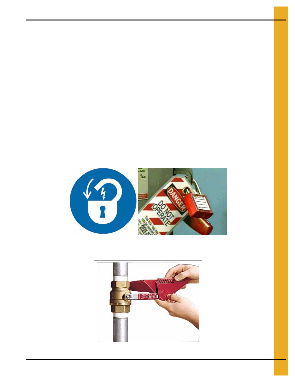
5. The equipment should be OFF and all power LOCKED OFF before work on or in the equipment.
Ensure the power isolator is OFF and LOCKED and TAGGED to prevent inadvertent re-start.
This must include all equipment attached to the dryer/bin on which you are working. (See Figure 1A.)
Figure 1A
6. Ensure the fuel supply is OFF and LOCKED. (See Figure 1B.)
Figure 1B
PNEG-1797CE CE Approved T-Series Tower Dryer 9
Page 10

1. Safety
7. NEVER attach lifting equipment to ladders or platforms.
8. When working on the equipment, NEVER go outside the safety rails provided.
9. NEVER walk on the roof of the equipment.
10. Do not work at heights during high winds, heavy rain, snow, ice or storm.
The majority of routine cleaning and service can be carried out from the service platforms provided.
However in exceptional circumstances it may be necessary to access other parts of the equipment. In
particular, in the rare event that access is required to repair or r eplace the g rain level switches. On th ese
occasions additional access and safety equipment may be required. Wherever possible we recommend
the use of powered access lift platforms or ‘cherry pickers’. In exceptional circumstances access may
require the use of safety harness. Such work must only be carried out b y specialist technicians trained and
qualified in working at heights and only after a complete risk assessment has been carried out and safe
working methods established.
Entering Grain Dryers
Wherever possible it is recommended not to enter grain dryers. However, if you have to enter the, observe
the following minimum
precautions:
1. NEVER
2. Make sure you are aware of all the possible hazards
3. Complete a risk assessment
4. You may need to complete a permit to work
approved by the dryer owner or supervisor.
5. Ensure the dryer has been purged of any products of combustion. Shut off the burner but leave the
fans running for at least 30 minutes before entry.
6. Do not smoke or use naked flames in or around the dryer.
7. Where there is a risk of harmful gases or vapors, check the atmosphere with a suitable analyzer. If
necessary, run the fans for longer to provide a safe breathable atmosphere. If in doubt do not enter
8. Switch OFF, lock and tag
equipment feeding and emptying the dryer. This will require turning the main power isolator to OFF,
LOCKING it and apply a TAG to prevent inadvertent re-start. (See Figure 1C on Page 11.)
allow a child or untrained, inexperienced person to enter a grain dryer at any time.
present within the dryer.
and identify any control measures that may be required, including:
• Personal protective equipment, such as hand, eye, foot, hearing, head and
respiratory protection.
• Safe access equipment.
• Safety equipment, such as safety line and harness.
• Supplementary lighting.
and prepare a safe system of work and have it
power supplies to ALL equipment associated with the dryer. Include
.
10 PNEG-1797CE CE Approved T-Series Tower Dryer
Page 11
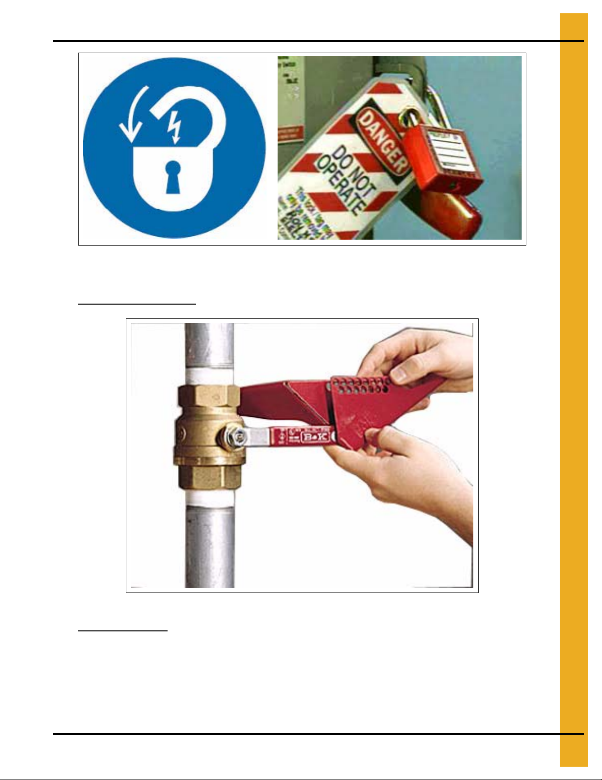
Figure 1C
9. You may also need to lock out any associated equipment attached to the dryer.
1. Safety
10. Shut OFF, lock and tag
the fuel supply at the main incoming valve. (See Figure 1D,)
Figure 1D
11. Never work alone, it is recommended to work in teams of at least three (3) so help is immediately
available in the event of emergency.
12. On completion of the work, check all team members are out of the dryer and all work tools have
been recovered.
13. Close and lock all dryer accesses.
14. Do not re-connect power or fuel supplies until approved by the dryer owner or supervisor.
PNEG-1797CE CE Approved T-Series Tower Dryer 11
Page 12
1. Safety
WARNING
Keep the dryer clean. Do not allow fine material to accumulate in the plenum
chamber or surrounding the outside of the dryer.
Precautions to Reduce Risk of Fire
Whilst the dryer has been designed to minimize the risk of ignition of combustible dust and dirt, this can
only be ensured by regular inspection and cleaning. At least every five (5) days.
1. Refer to Page 10 for required precautions before entering the dryer. The dryer must be locked out
and tagged at the main power and fuel supply before entering.
2. Open the dryer access hatches and check for any significant build-up of dust or particles of grain.
3. Using an industrial vacuum cleaner, clean the plenum. Do not use compressed air.
4. Check inside other dryer accesses and clean as required.
5. Check all personnel are out of the dryer, close and lock all accesses before re-starting drying.
6. This procedure may be carried out more regularly in conditions of extreme dust and dirt.
Exercise greater caution when drying highly flammable grains and seeds. For example rapeseed, can ola,
linseed, sunflower and milo.
All grain and seed must be whole (minimal cracked or crushed), clean and dust free.
Dry at low temperatures (< 40°C).
Avoid dust and chaff being drawn into the fan and heater.
Keep the fan, heater, drying plenum and ducts clean at all times.
In the event of a fire (or suspected fire).
• Shut down the entire dryer.
• Turn OFF fuel at the tank or supply valve.
• Shut off and lock electrical power.
• Evacuate the area.
• Call the fire department.
Use Caution in the Operation of this Equipment
This dryer is designed and manufactured with operator safety in mind. However, the very nature of a grain
dryer having a gas burner, high voltage electrical equipment and high speed rotating parts, presents
hazards to personnel which cannot be completely safeguarded against withou t interfering with the efficient
operation of the dryer and reasonable access to its components.
Use extreme caution at all times when working on or around the dryer.
Continued safe, dependable operation of automatic equipment depends, to a great degree, upon the
owner. Follow the recommendations within the Owner’s Manual and make it a practice to regularly inspect
the unit for any developing problems or unsafe conditions.
Take special note of the safety precautions on Page 8 before attempting to operate the dryer.
12 PNEG-1797CE CE Approved T-Series Tower Dryer
Page 13
2. Decals
Safety decals must be read and understood by all people in and around the dryer area. If a ny safety decals
are not displayed on the dryer or if they are damaged, contact The GSI Group, Inc. for replacement:
International Decals
International, translated versions of the decals fitted to the equipment are available as part of the
Language Pack that was supplied with the product. If you need further copies or a different language,
please contact GSI or you dealer.
The international decals have been designed to be placed directly over the USA standard versions.
Normally these will be factory fitted, but if you need to change them, please refer to the decal cross
reference sheet, provided with the Language Pack and the decal locations given in the user’s manual.
Decals
1004 E. Illinois St.
Assumption, IL. 62510
Phone: 1-217-226-4421
PNEG-1797CE CE Approved T-Series Tower Dryer 13
Page 14
2. Decals
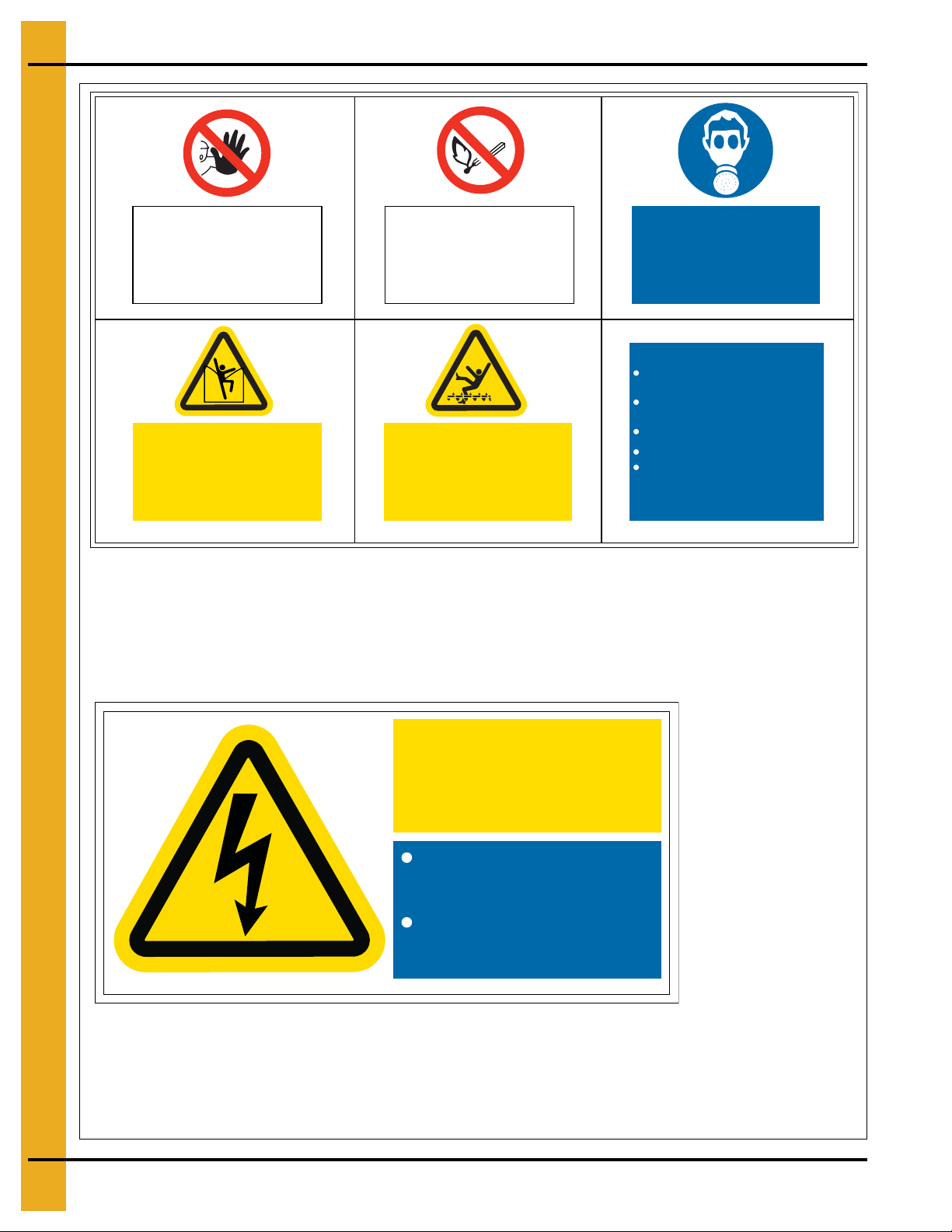
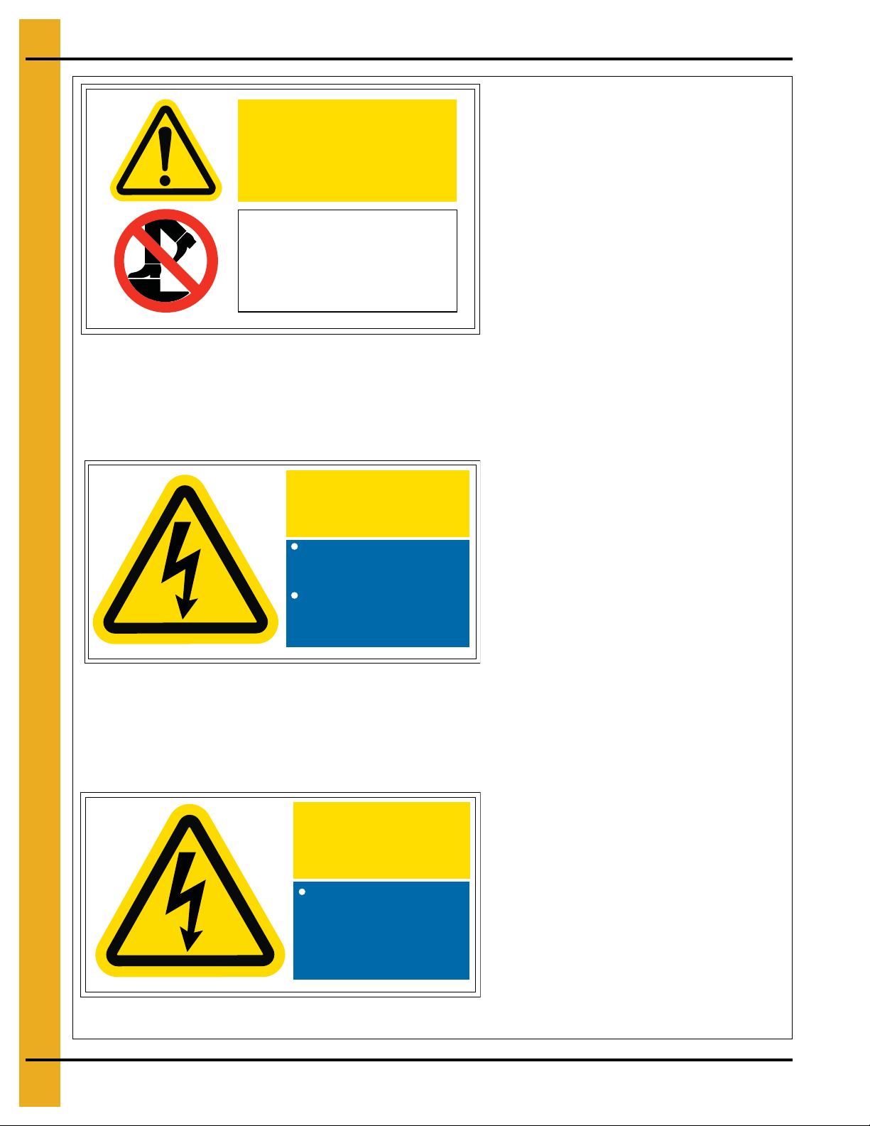
DC-2163
DC-2163 is located on outside and inside of the main power panel doors.
Quantity: 3
DC-2161
DC-2161 is located on inside and outside of the roof access hatches.
Quantity: 2
No entry to
unauthorised
personnel
Suffocation and
Entrapment Hazard
Do not walk directly
on stored material
No smoking or
naked flames
Automatic Machinery
Isolate and lock all power
before entering this bin
Respirators
must be worn
in this area
Before entering:
Permit required for entry into
confined space
Disconnect and lock all electrical
power
Disconnect and lock fuel supply
Use safety harness and safety line
Ensure someone else is outside
the bin
DC-2161
High
Voltage
Isolate and lock from power
before removing guards or
opening enclosure
Replace all guards and lock
enclosure before reconnecting
to power
DC-2163
14 PNEG-1797CE CE Approved T-Series Tower Dryer
Page 15
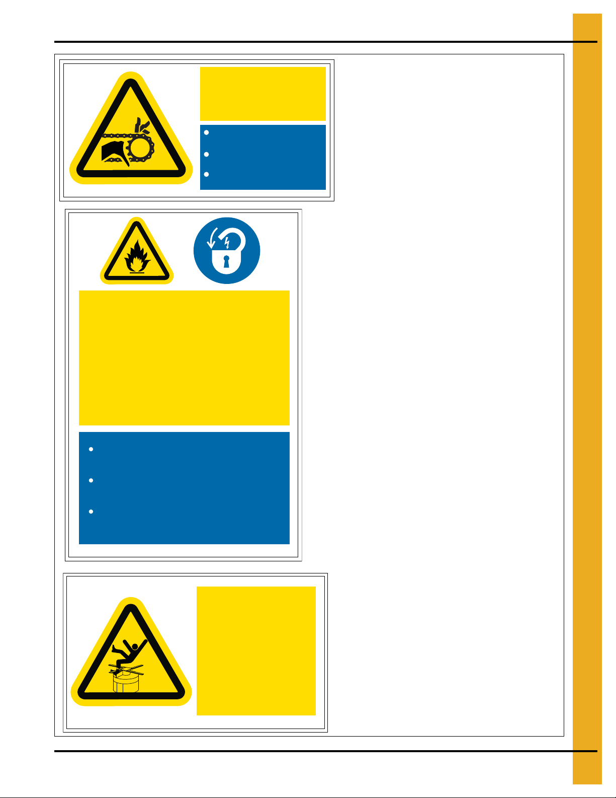
2. Decals
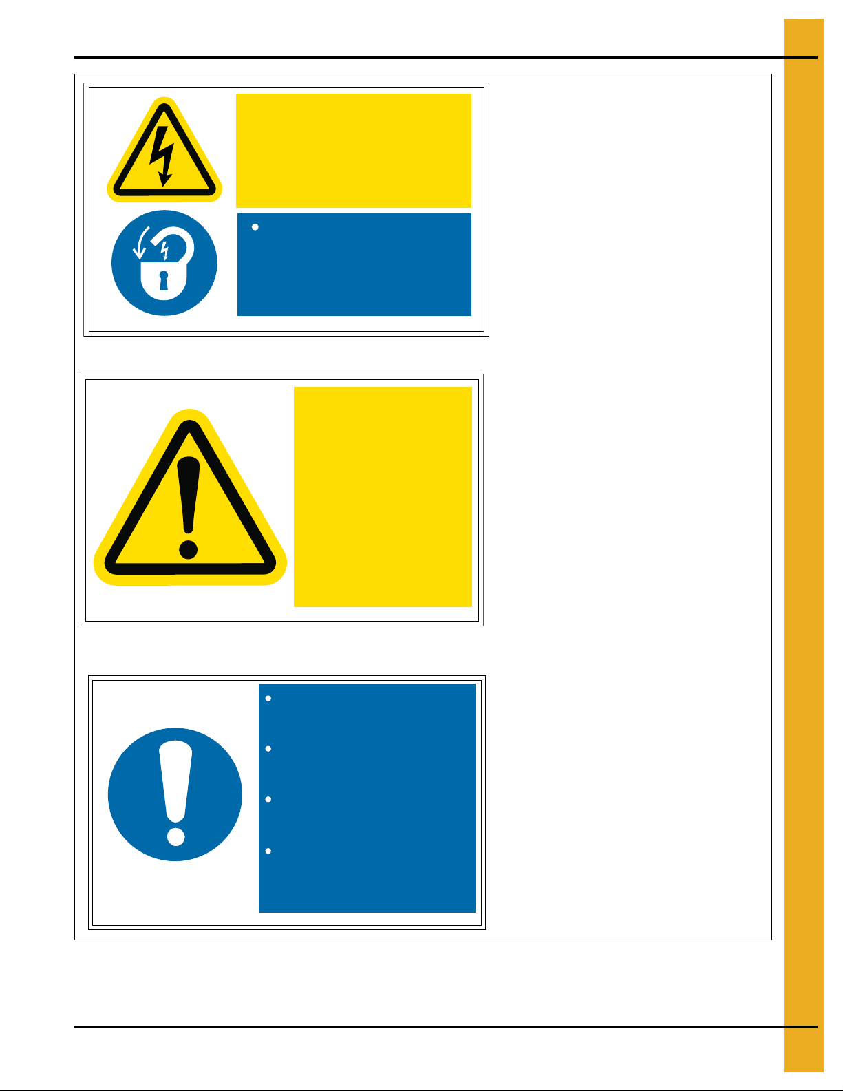
Do not stand on
rotating drum
Serious injury
may result
DC-2212
Rotating drum
below
DC-2212
DC-2212 is located on the outside of the hopper
service access hatch.
Quantity: 2
Do not operate with guards
removed
Isolate and lock from power
before removing guards
Replace all guards before
reconnection to power
Automatic
Machinery
DC-2164
DC-2165
DC-2165 is located on the heat section inner and
outer access hatches.
Quantity: 2
DC-2164
Background: White
Colors: Black, ANSI Yellow and ANSI Blue
Size: 3.940" x 1.970"
DC-2165
Do not open door while drier is
running
Disconnect and lock electric and
gas supply before opening
Close and lock door before
reconnecting
High Temperature
and Pressure
Equipment Can Start
Unexpectedly
PNEG-1797CE CE Approved T-Series Tower Dryer 15
Page 16
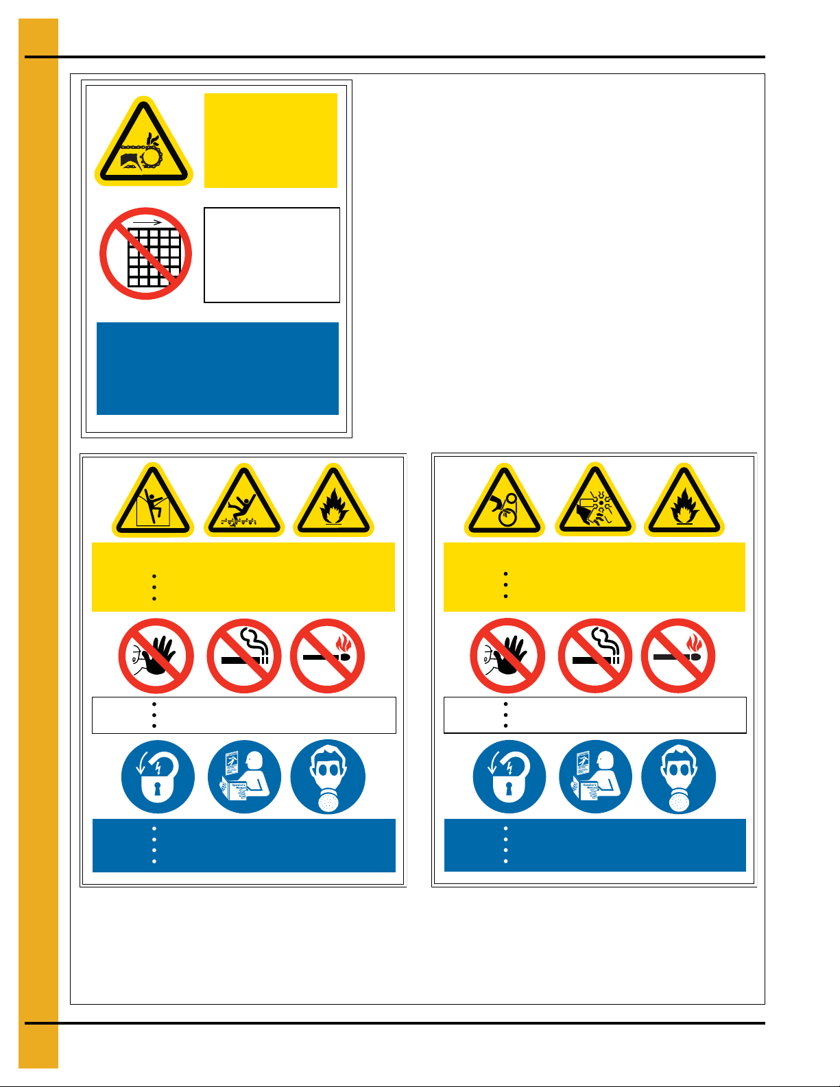
2. Decals
Confined Space
High Temperature
Exposed fan and belt drive
Automatic machinery
No unauthorized access
No smoking
No exposed flames
Lock out all electrical power before entering
Lock out fuel supply before entering
Refer to owners manual before entering
Wear respiratory protection
DC-2216
DC-2216
DC-2216 is located on the cool section (intake plenum)
access hatch.
Quantity: 1
Confined Space
High Temperature
Powered machinery can kill or dismember
Flowing material will bury and suffocate
No unauthorized access
No smoking
No exposed flames
Lock out all electrical power before entering
Lock out fuel supply before entering
Refer to owners manual before entering
Wear respiratory protection
DC-2215
DC-2215
DC-2215 is located on upper and middle level
access hatches.
Quantity varies with size of dryer.
DC-2214
DC-2214 is located on the grain sampling access hatch.
Quantity: 1
Automatic
conveying
equipment
Do not remove
guarding
Grain Sampling Point
below
DC-2214
16 PNEG-1797CE CE Approved T-Series Tower Dryer
Page 17
2. Decals
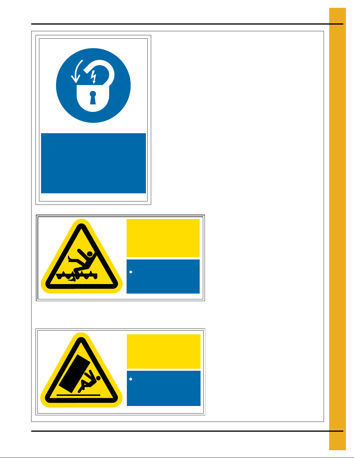
Electrical Lockout
DC-2217
BEFORE working on or in the dryer
SWITCH OFF, LOCK and TAG
to prevent accidental start-up
DC-2217
DC-2217 is located adjacent to the electrical lock out handle on
the main power panel.
Quantity: 1
DC-2230
Background: White
Colors: Black, ANSI Y ellow and ANSI Blue
Size: 6.000" x 3.000"
DC-2231
DC-2231 is located on the outside of the
main power panel doors.
Quantity: 2
DC-2230
Lock out all electrical
power before entering
Auto equipment can
start at any time
Rotating auger will
crush and cut
DC-2231
Secure legs to
foundation prior to
opening doors
Crush
Hazard
PNEG-1797CE CE Approved T-Series Tower Dryer 17
Page 18
2. Decals
DC-2233
If an overload or a fault current
interruption occurs, circuits must
be checked to determine the cause
of the interruption
If a fault condition exists, the
current-carrying components should
be examined and replaced if
damaged, and the integral current
sensors must be replaced
Electric shock and
fire hazard
DC-2234
To maintain overcurrent short
circuit and ground fault
protection, the manufacturer’s
instructions for selecting
overload relays and setting
the instantaneous trip circuit
breaker must be followed
Electric shock and
fire hazard
DC-2234
DC-2234 is located on inside main power
panel door.
Quantity: 1
DC-2233
DC-2233 is located on inside main power
panel door.
Quantity: 1
DC-2232
DC-2232 is located on roof panels adjacent
to roof steps.
Quantity: 4
Slip and fall hazard
Can cause severe
injuries
Do NOT step or stand
in this area
DC-2232
18 PNEG-1797CE CE Approved T-Series Tower Dryer
Page 19
DC-2235
High Voltage
Insure that the incoming AC
power and all separate power
sources are turned off and
locked before working on this
equipment
Failure to observe practice
below may result in severe
injury, death, and/or
equipment damage
All maintenance
DC-2235
DC-2235 is located on inside and outside
main power panel door.
Quantity: 2
DC-2236
DC-2236 is located on inside main power
panel door.
Quantity: 1
DC-2237
DC-2237 is located on inside main power
panel door.
Quantity: 1
procedures must be
performed by qualified
personnel who are
familiar with the
operation of this
equipment.
2. Decals
For precise location of all safety decals, please refer to manual provided with the language pack for
the dryer.
PNEG-1797CE CE Approved T-Series Tower Dryer 19
Failure to observe this
warning can result in
serious or even fatal
injury and/or equipment
damage.
DC-2236
Be sure that charge light and all
LED’s are out before touching any
components.
All test equipment should be
connected and disconnected with
power off.
Ground test equipment, such as
Insure that the incoming AC
oscilloscopes, may damage the
power and all separate power
inverter.
sources are turned off and
locked before working on this
Isolate all instruments from
equipment
ground before using. The DC bus
remains charged for several
minutes after power is removed.
DC-2237
Page 20
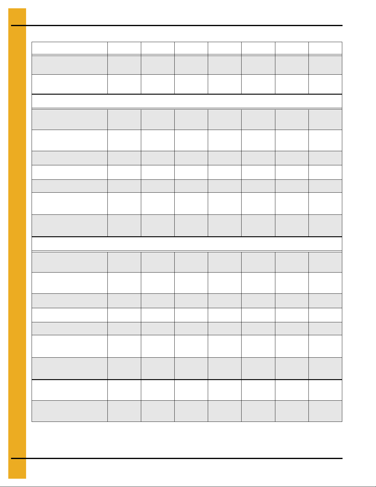
3. Specifications
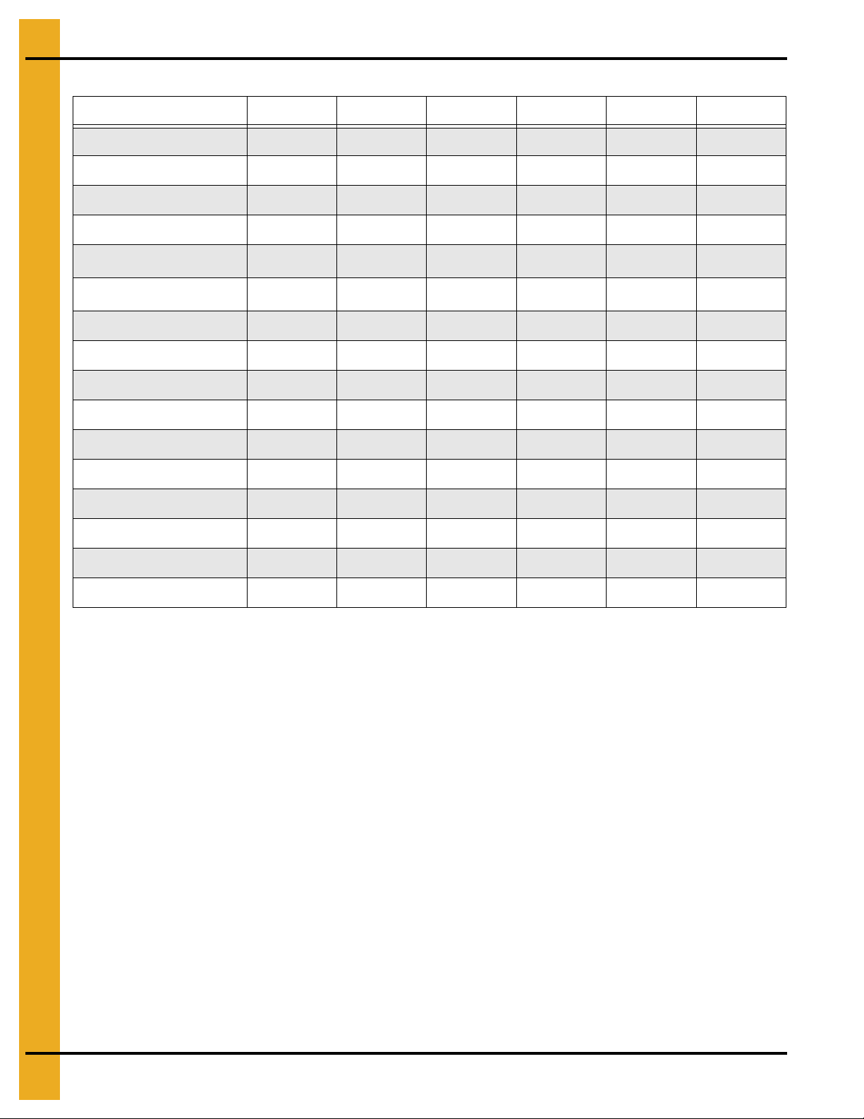
Dryer Specifications
Models 1050 1260 1575 1875 20100 24100
Blower Size 43" Axial 43" Axial 8490 8542 8542 8600
Blower RPM 1750 1750 1035 856 981 818
Blower kW 37.50 45.00 56.25 56.25 75.00 75.00
Metering kW 0.75 0.75 0.75 0.75 0.75 0.75
Drying m3/s
3
Cooling m
Grain Column 324 mm 324 mm 324 mm 324 mm 324 mm 324 mm
Tower Diameter 3.65 m 3.65 m 3.65 m 3.65 m 3.65 m 3 .65 m
Overall Height 13.9 m 15.9 m 18.0 m 21.0 m 23.1 m 26.1 m
Wet Holding (T) 7.677.677.677.677.677.67
Heat Holding (T) 15.49 19.20 23.22 29.41 31.90 38.07
Cool Holding (T) 5.56 6.81 7.75 8.99 11.46 12.70
Dryer Holding (T) 31.29 36.25 41.20 48.64 53.59 60.99
Outside Catwalks 001223
T/H (20%-15%) 25 30 38 46 51 61
T/H (25%-15%) 151823273037
/s
19.98 22.86 36.42 38.63 46.57 51.15
6.85 8.27 18.21 19.32 23.28 25.58
Electrical
Standard voltages are:
1. 240V, 480V or 575V, 60 Hz
2. 380V, 400V or 415V, 50 Hz
The power panel includes:
1. Main power disconnect.
2. Motor starters and overloads (standard direct on line, star/delta and soft start are options).
3. Control circuit breakers for the individual blower motors.
4. Auxiliary 7.5 kW motor starters for dry and wet grain handling equipment.
5. A correctly designed power supply is required, including safety earth connection.
Please note that the figures given on Page 72 are minimum figures and do not take into account starting
currents. Please allow for these when designing the required power supply for the dryer.
20 PNEG-1797CE CE Approved T-Series Tower Dryer
Page 21
3. Specifications
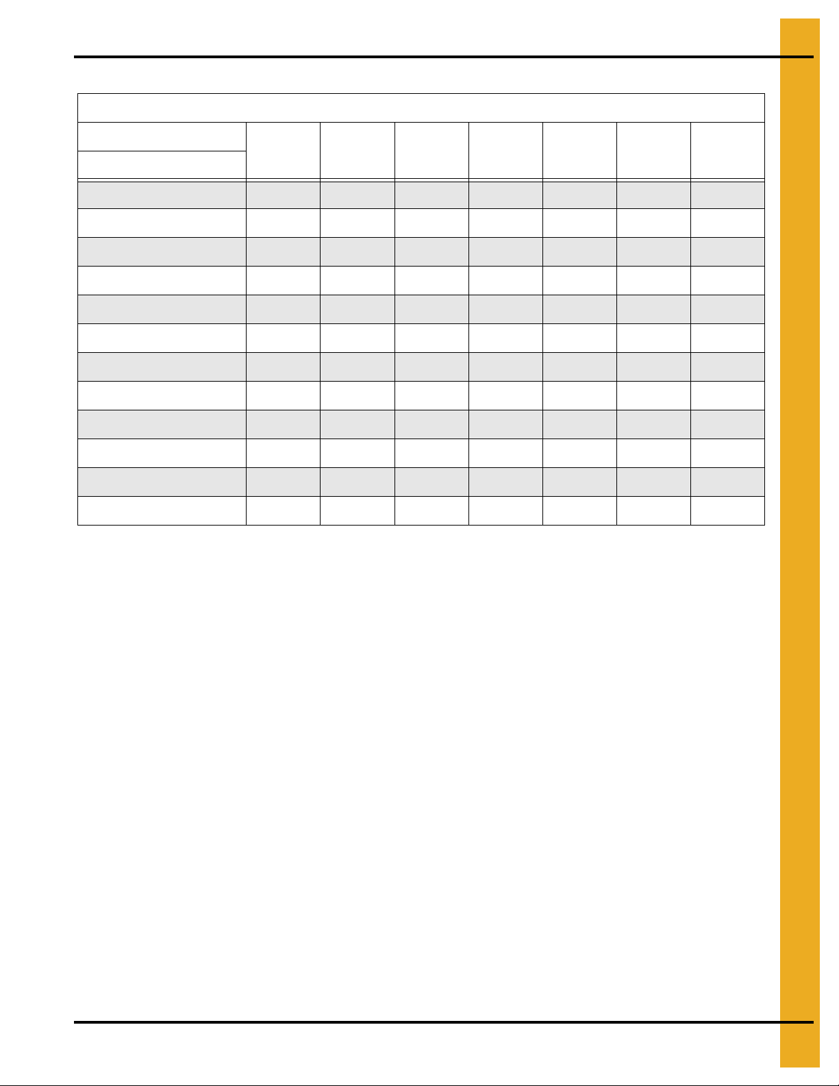
Minimum Electrical Power Requirements
3 Phase Power Requirements (A)
Supply Voltage
230 380 400 415 440 460 575
Model #
T-1050 204 123 117 113 106 102 81
T-1260 226 136 130 125 118 113 90
T-1575 258 156 148 143 135 129 103
T-1875 258 156 148 143 135 129 103
T-20100 316 191 181 175 165 158 126
T-24100 316 191 181 175 165 158 126
F-1050 204 123 117 113 106 102 81
F-1260 226 136 130 125 118 113 90
F-1575 258 156 148 143 135 129 103
F-1875 258 156 148 143 135 129 103
F-20100 316 191 181 175 165 158 126
F-24100 316 191 181 175 165 158 126
Fuel
1. Fuel types are LPG or natural gas vapor.
2. Minimum supply pressure is,
a. 350 mBar natural gas at full burner flow rate.
b. 350 mBar LPG vapor at full burner flow rate. Higher pressures may be required to obtain
maximum burner output.
3. Burner flow rates are as table on Page 22.
PNEG-1797CE CE Approved T-Series Tower Dryer 21
Page 22
3. Specifications
T-Series and F-Series Fuel Specifications
T-Series and F-Series T/F-1050 T/F-1260 T/F-1575 T/F-1875 T/F-1054 T/F-20100 T/F-24100
Maximum Burner
Output (kW)
Average Burner
Output (kW)
LPG Fuel LPG Gross CV
Maximum Gas Flow
LPG (m
3
/h)
Average Gas Flow
3
LPG (m
/h)
Supply Pressure (mBar1)
Regulator Setting (mBar2)
3254 3831 4882 5180 6244 6858 7722
1871 2203 2807 2979 3590 3943 4440
93.8 MJ/m
3
125 147 187 199 240 263 296
72 85 108 114 138 151 170
350-700 350-700 350-700 350-700 350-700 350-700 350-700
206 206 206 206 206 206
Regulator Spring Black Cadmium Cadmium Cadmium Cadmium Cadmium Cadmium
Burner Pressure High-Fire
2
O6)
mm (H
Burner Pressure Low-Fire
2
O7)
mm (H
418 1375 807 1189 1447 972
16.7 55.0 32.3 47.5 57.9 38.9
Natural Gas Fuel NG Gross CV
Maximum Gas Flow
3
NG (m
/h)
Average Gas Flow
3
NG (m
/h)
Supply Pressure (mBar1)
Regulator Setting (mBar2)
303 357 455 483 582 640 720
174 205 262 278 335 368 414
350-700 350-700 350-700 350-700 350-700 350-700 350-700
21 206 206 206 206 206 206
39 MJ/m
3
Regulator Spring Black Cadmium Cadmium Cadmium Cadmium Cadmium Cadmium
Burner Pressure High-Fire
mm (H
2
O6)
Burner Pressure Low-Fire
mm (H
2
O7)
Pressure Relief
Set Point (mBar
4
)
Over Pressure Valve
5
Set Point (mBar
)
500 500 500 500 500 500 500
450 450 450 450 450 450 450
719 1189 697 1009 1241 855
28.8 47.6 27.9 40.3 49.7 34.2
22 PNEG-1797CE CE Approved T-Series Tower Dryer
Page 23
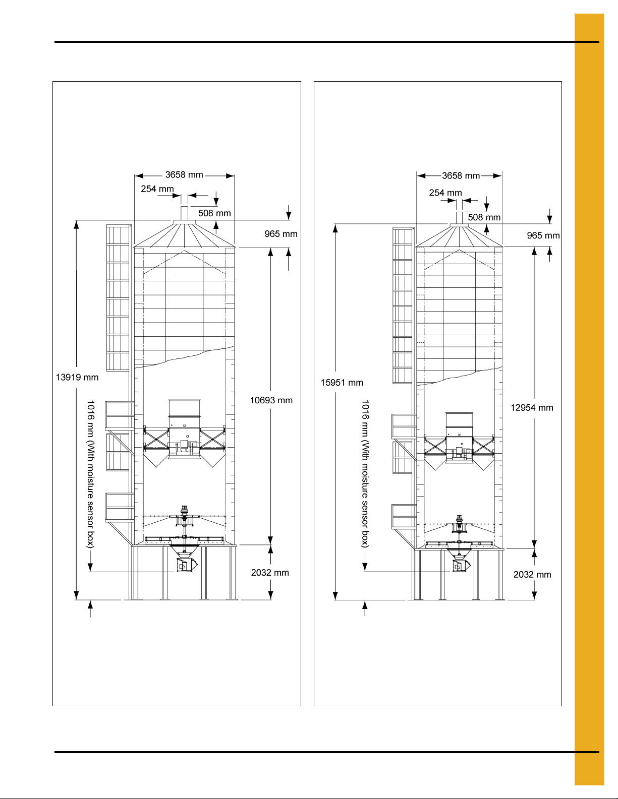
Dimensions
3. Specifications
Figure 3A 1050 Figure 3B 1260
PNEG-1797CE CE Approved T-Series Tower Dryer 23
Page 24
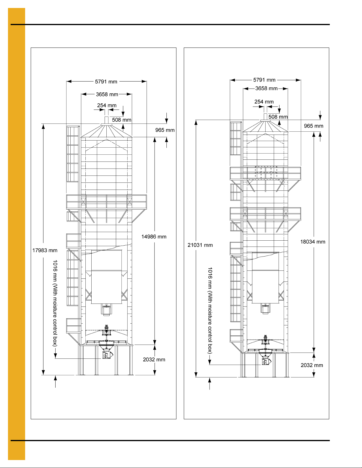
3. Specifications
Dimensions (Continued)
Figure 3C 1575 Figure 3D 1875
24 PNEG-1797CE CE Approved T-Series Tower Dryer
Page 25
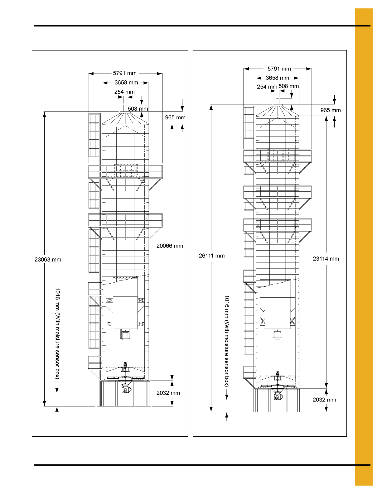
Dimensions (Continued)
3. Specifications
Figure 3E 20100
PNEG-1797CE CE Approved T-Series Tower Dryer 25
Figure 3F 24100
Page 26

4. Dryer Installation
Dryer Layout
System Layout
When considering dryer location make allowance for:
1. Grain handling systems.
2. Location of storage bins.
3. Wet grain supply.
4. Prevailing wind direction.
5. Fuel and power supply.
6. Noise.
7. Control panel location.
Site Location
Do not locate the dryer:
1. Inside a building.
2. Adjacent to combustible material which may be sucked in.
3. Within 2.0 m of other structures. Refer to specifications on Pages 20-22 and dimensions
on Pages 23-25.
You may need to obtain local permission for the dryer construction and should also consider:
1. Electrical code.
2. Fuel installation regulations.
3. Insurance requirements.
Foundation
Standard foundation details are given in Figure 4A on Page 27 and Figure 4B on Page 28. For ground
conditions outside of these standards a local engineer will be required to carry out site specific
foundation design.
26 PNEG-1797CE CE Approved T-Series Tower Dryer
Page 27

4. Dryer Installation
Standard Base for Models 1050, 1260, 1575, 1875 and 20100
Figure 4A
PNEG-1797CE CE Approved T-Series Tower Dryer 27
Page 28

4. Dryer Installation
Standard Base for Model 24100
Figure 4B
28 PNEG-1797CE CE Approved T-Series Tower Dryer
Page 29

4. Dryer Installation
Fuel Connections
LPG Dryers with Internal Vaporizers
The dryer is designed to operate on liquid LPG with gross calorific value of 93.8 MJ/m3. The fuel supplier
should provide liquid fuel from the tank to intake point at the strainer on the dryer pipe train.
Natural Gas (NG) Dryers
The dryer is designed to operate on natural gas with gross calorific value of 39.0 MJ/m3. The dryer is
equipped with a natural gas supply pipe system connected to the heater solenoid valves. A regulated
pressure of 700 mBar must be provided at the connection to the dryer, with gas available in sufficient
volume to maintain operating pressure.
Commissioning Checks
Before starting the dryer check:
1. Pressure tightness.
2. Over pressure valve operation.
3. Pressure relief operation.
4. Maximum pressure switch operation.
Electrical Connection
1. Power supply must be adequate for the full current draw, plus starting loads for the electrical
equipment on the dryer.
2. Power is connected into the main disconnect in the dryer power panel.
3. The dryer must be properly earthed (grounded), which may require the installation of a suitable
ground rod. This must be designed and carried out by a suitably qualified electrician in accordance
with local regulations and codes and taking into account site ground conditions.
4. Earth connection should be made into the PE terminal in the power panel and to a suitable location
on the dryer structure.
5. The electrical installer should carry out full electrical safety checks including earth continuity during
commissioning of the dryer.
Connecting Auxiliary Conveyors
Auxiliary load and unload equipment can be wired directly to the dryer.
1. Maximum power not to exceed 7.5 kW.
2. Larger than 7.5 kW must be powered from an alternative source and contactor, though control may
be run through the dryer control panel.
PNEG-1797CE CE Approved T-Series Tower Dryer 29
Page 30

5. Operating Controls
Heater switch
Fan switch
Load auger switch
Unload auger switch
Operator light switch
Control power switch
Stop switch
Start switch
Meter roll speed
Touch screen
WARNING
Switches on the vision panel are for control purposes only. For servicing and
maintenance switch OFF and lock at the main disconnect.
Vision Control Panel Layout
Figure 5A
Vision controls are used on several GSI drying products. It can operate any dryer in either a batch or a
continuous flow mode. All operating instructions for the T-Series dryer describes continuous flow
operation only.
30 PNEG-1797CE CE Approved T-Series Tower Dryer
Page 31

5. Operating Controls
1. CONTROL POWER switch turns ON/OFF power to the control.
2. FAN switch starts/stops the fan. AUTO position is not used on T-Series and F-Series dryers.
3. HEATER switch turns the heater ON/OFF. AUTO position is not used on T-Series and
F-Series dryers.
4. LOAD AUGER switch selects operating mode wet fill conveyor. In AUTO and MANUAL, the wet fill
conveyor operates to keep the dryer full. In AUTO only the dryer shuts down if it is low on grain for a
pre-set period.
5. UNLOAD switch controls ‘Accutrol’ metering system and unload conveyor. In MANUAL, the
metering system operates at the speed set by the METERING ROLL SPEED switch. In AUTO, it runs
in multi-speed mode, controlled by the automatic moisture control.
6. OUTSIDE LIGHT switch controls the service light. In AUTO, the light is ON while the dryer is running
and OFF when shut down.
7. START switch starts and operates the dryer.
8.
STOP switch
the stop has been pressed. To stop the blower before this time, turn the BLOWER switch to OFF.
stops all dryer functions except the blower which will continue to run for 15 minutes after
The STOP switch is also used to re-set after a shut down.
PNEG-1797CE CE Approved T-Series Tower Dryer 31
Page 32

6. Vision Touch Screen Display
These two (2) buttons are
used to update software.
(See PNEG-1506 vision
programming manual.)
2
3
4
5
1
Boot screen appears when the control power is switch ON. (See Figure 6A.)
Figure 6A
Default operation screen opens when START DRYER is pressed.
Figure 6B
32 PNEG-1797CE CE Approved T-Series Tower Dryer
Page 33

6. Vision Touch Screen Display
Modify button
1. Dryer operation animation shows the status of the fan/heaters, load and unload augers and meter
rolls. Also grain temperature, moisture content, M/C set point and tones counter.
2. Dryer status indicates if the dryer is stopped, started, loading or unloading.
3. Dryer status chart shows the grain temperature, moisture in/out, temperature out and metering roll
speed. Over a period of time.
4. Plenum shows the plenum temperature set point (SP), actual plenum temperature and
burner status.
5. Setup buttons provides access to timers, temperature set points, dryer model and moisture
control setup.
Figure 6C
Select Data Log Sample Time
To change the sample time:
1. Press modify.
2. Select required time.
3. Press Accept/Exit.
To clear the table, press Clear Table button. (See Figure 6C.)
PNEG-1797CE CE Approved T-Series Tower Dryer 33
Page 34

6. Vision Touch Screen Display
Optional Operation Screen
Press View button give four (4) options. (See Figure 6D.)
Figure 6D
1. Table view: Default operation screen view. (See Figure 6B on Page 32.)
2. Graph view:
a. Press then .
b. Press any of to select which data is graphed.
c. Press to select time period.
3. Owner’s manual: See Page 40.
4. History: See Page 41.
34 PNEG-1797CE CE Approved T-Series Tower Dryer
Page 35

Setting the Timers
Operation screen for setting timers
Modifying timer set point
Press to open the timers screen. (See Figure 6E.)
6. Vision Touch Screen Display
1. Press to set the load system delay during unload. Reduces load motor cycling.
2. Press to set the dryer shut down delay after the OUT OF GRAIN switch opens.
Set to the maximum time for the dryer to refill during drying (this is displayed during loading on
the screen).
3. Press to set the time between sequential fan starts (multiple fan dryers only).
4. Press to set the unload system overrun following metering system shut down
(allows unload system to clear itself).
PNEG-1797CE CE Approved T-Series Tower Dryer 35
Figure 6E
Page 36

6. Vision Touch Screen Display
5. Use when setting timers. Note default values may be entered.
6. Press then to return to the operation screen. (See Figure 6B on Page 32.)
Setting the Temperatures
1. Press to display temperature setup screen. (See Figure 6F.)
Figure 6F
2. Press then use key pad to alter plenum temperature.
3. Press then use key pad to alter grain temperature.
Note default units are °F. This can be changed to °C in SETUP.
4. Press then to return to the operation screen.
36 PNEG-1797CE CE Approved T-Series Tower Dryer
(See Figure 6B on Page 32.)
Page 37

The Setup Screen
Press adjust other dryer settings.
6. Vision Touch Screen Display
Figure 6G
1. select continuous flow or staged batch drying modes.
2. adjust time and date settings.
3. select correct dryer model an details, as follow:
a. Number fan/heaters = 1
b. Load system = end
c. Dryer length (ft.) = 22 (Models 1875, 20100 and 24100)
18 (Models 1050, 1260 and 1575)
d. Number modules = 1
e. Fuel = LP
4. See Page 57 for detailed setup.
PNEG-1797CE CE Approved T-Series Tower Dryer 37
Page 38

6. Vision Touch Screen Display
5. changes between SI and American units.
6. see service section on Page 65.
7. burner mode should be ALL HIGH/LOW. (See Figure 6H.)
Figure 6H
8. to adjust the switching range of the burner. (See Figure 6I on Page 39.) Default is
3°F (1°C). Tower dryers have just 1 plenum.
38 PNEG-1797CE CE Approved T-Series Tower Dryer
Page 39

6. Vision Touch Screen Display
Figure 6I
9. allows the dryer throughput meter to be calibrated on Figure 6J.
Setting = (Actual tons per hour/Recorded tons per hour)*100
Figure 6J
PNEG-1797CE CE Approved T-Series Tower Dryer 39
Page 40

6. Vision Touch Screen Display
Viewing the Owner’s Manuals on the Display Screen
Press then the Owner’s Manual button. (See Figure 6K.)
At the explorer screen, double press the manual and wait for it to open on screen.
Figure 6K
Use the scroll bar to navigate the manual. (See Figure 6L.)
Figure 6L
40 PNEG-1797CE CE Approved T-Series Tower Dryer
Page 41

Viewing the Dryer Shut Down History
Press and then history. (See Figure 6M.)
6. Vision Touch Screen Display
Figure 6M
The shut down history is displayed and can be copied to a flash disc for viewing on another computer.
PNEG-1797CE CE Approved T-Series Tower Dryer 41
Page 42

7. Dryer Start-Up
WARNING
BEFORE STARTING THE DRYER. All safety guards must be in place. All personnel
must away from the dryer. All access doors must be closed.
Dryer Commissioning
Electrical
1. Carry out earth bonding test per EN60204 and/or local electrical laws and regulations.
2. Check adequate power supply. (Refer to table on Page 22.)
3. Voltage at phases must be within 5% of rated voltage.
4. Voltage drop must not exceed 5% when under full load.
5. Check overload settings for each motor circuit.
6. Complete full electrical tests in accordance with EU directives and local laws, regulations and codes.
Gas Train
1. Pressure test
a. Close inlet valve. (See Figure 7E on Page 50.)
b. Close firing valve. (See Figure 7I on Page 52.)
c. Close pilot line valve. (See Figure 7G on Page 51.)
d. Fit pressure test nipple into main solenoid inlet flange.
e. Attach hand bellows and pressure gauge.
f. Pressurize gas train with air to 35 kPa (350 mBar).
g. Check for pressure loss at gauge.
h. Use leak detection to test for leaks.
i. Repeat on outlet flange.
j. Repeat on pilot line.
2. Set inlet pressure per table on Page 22.
3. Set relief valve per table on Page 22.
a. Apply air pressure via main solenoid inlet flange.
b. Increase/decrease spring pressure in relief valve.
c. Valve should open at 50 kPa maximum.
42 PNEG-1797CE CE Approved T-Series Tower Dryer
Page 43

4. Set over pressure shut off (OPSO) per table on Page 20.
a. Apply air pressure via main solenoid inlet flange.
b. Increase/decrease spring pressure in OPSO.
c. Valve should shut at 45 kPa maximum.
5. Set operational pressure per table on Page 22.
a. Open main gas valve.
b. Adjust pressure at regulator.
6. Set pilot flow rate.
a. Close pilot line manual shut off valve. (See Figure 7G on Page 51.)
b. Close ‘firing valve’ on main gas line. (See Figure 7I on Page 52.)
c. Start blowers.
d. Start burners.
e. When pilot solenoid valve opens, adjust flow rate to give pilot pressure of 4 kPa.
7. Dryer Start-Up
f. Adjustment is on pilot solenoid valve. (See Figure 7A.)
g. Open pilot line manual shut off valve. (See Figure 7G on Page 51.)
h. Re-set burner control. (It will have gone to lock out after previous attempt to light.) Reset can be
done by cycling the burner switch on the PLC panel.
i. Start burner.
j. Pilot should now light and stay alight. After 10 seconds, main valve should open and a fter further
4 seconds burner control revert to lock out and pilot extinguish (main flame is shut off). If pilot
does not stay alight, then the pressure and/or flame rod will need to be adjusted to ensure the
burner control is getting a strong flame current. See Step 7 on Page 44.
Figure 7A Pilot Valve Flow Adjustment
PNEG-1797CE CE Approved T-Series Tower Dryer 43
Page 44

7. Dryer Start-Up
7. Checking pilot flame current.
a. The minimum flame signal, measured at the burner control, should be 1.25 VDC.
b. Flame signal can be checked at the Honeywell burner control, located in the main power panel,
as shown in Figure 7C on Page 45.
c. Flame rod may be re-positioned or gently bent to get better contact with the flame. Ensure rod is
well clear of burner to prevent grounding when hot. Be careful not to damage ceramic insulator
surrounding flame rod. (See Figure 7B.)
d. Check burner is properly grounded.
e. Check neutral supply to burner control is 0 VAC.
Figure 7B Burner End Plate, Spark, Pilot and Flame Rod Locations
Ref # Description
2 Main Gas
3 UV Sensor Connection (Optional)
4 Spark Ignitor
5 Flame Rod Locations
5* Flame Rod Alternate Locations
6Pilot Gas
NOTE: Minimum acceptable flame signal is 1.25 VDC.
44 PNEG-1797CE CE Approved T-Series Tower Dryer
Page 45

7. Dryer Start-Up
Flame simulator
test jack
Negative (-)
meter lead
Positive (+)
meter lead
One mega
ohm/volt meter
Figure 7C Honeywell Test Flame
8. Set burner high-fire pressure.
a. Re-open main gas ‘firing valve’. (See Figure 7I on Page 52.)
b. Note required high-fire pressure from table on Page 22.
c. Set plenum temperature to approximately 100°C above ambient.
d. Light burners.
e. Check modulating valve has driven fully open.
f. Read pressure at burner gauge. (See Figure 7I on Page 52.)
g. Adjust pressure a regulator to give required pressure.
h. Lock regulator.
9. Set burner low-fire pressure.
a. Set plenum temperature to approximately 5°C above ambient.
b. Light burners.
c. On low-fire, adjust modulating valve minimum setting to give pressure as per table on Page 20.
10. Read pressure at burner gauge. (See Figure 7I on Page 52.)
PNEG-1797CE CE Approved T-Series Tower Dryer 45
11. Run burners and check burner modulates correctly.
12. Check gas pressure remains stable.
13. Fill out gas train commissioning check sheet. (See Page 4.)
Page 46

7. Dryer Start-Up
Pre-Season Checks
1. Inspect the accutrol metering system.
a. Open the two (2) access doors and inspect the sweep metering system to ensure that the system
is able to move freely.
2. Gas train
a. Check for any leaks by pressurizing the line with air and using gas leak disclosing so lution or by
doing pressure loss tests.
b. Leaks must be rectified by opening and resealing the joint.
3. Wiring
a. Check wiring on the dryer and inside the control panels for signs of damage or loose connections.
Rectify any faults.
4. Electrical power
a. Check all circuit breakers in the panel are closed.
b. Turn ON the electrical power supply to the dryer.
c. Check for correct voltage on all phases.
5. CONTROL POWER switch
a. Turn the CONTROL POWER switch to ON.
b. At boot screen appears (See Figure 6A on Page 32), press .
c. Any faults will be displayed on the Main screen.
d. If no faults are found safe, the START switch will illuminate.
46 PNEG-1797CE CE Approved T-Series Tower Dryer
Page 47

6. START switch
a. Check all selector switches are OFF.
b. Push the DRYER START switch.
c. Selector switches be activated.
7. Fuel check
a. Open the gas supply to the dryer.
b. Check correct supply pressure. (See Table on Page 22.)
8. Load auger. With grain supply OFF.
a. Start and stop load auger to check correct operation and rotation.
b. Turn the load auger to AUTO and allow to run for 8 minutes.
c. Dryer should stop and display OUT OF GRAIN error message.
d. Press STOP to clear message.
9. Unload operation
7. Dryer Start-Up
a. Turn unload auger to AUTO. Check correct operation and rotation.
b. Turn unload auger to MANUAL position. Check correct operation and rotation.
10. Accutrol sweep metering system operation
a. With unload in AUTO, check metering speed increases and decreases as control is adjusted.
b. Turn unload OFF. Unload will continue for 60 seconds and shut down.
11. FAN switch
a. Turn FAN switch to ON the OFF and check correct operation and rotation.
12. Burner safety
a. Turn fuel OFF.
b. Start the fan.
c. Turn HEATER switch to ON.
d. Burner should attempt to light and then lockout.
e. Display should read “Ignition Failure Fan 1”.
PNEG-1797CE CE Approved T-Series Tower Dryer 47
Page 48

7. Dryer Start-Up
13. Burner test fire
a. Turn fuel ON.
b. Set plenum temperature to 60°C.
c. Start the fan.
d. Turn HEATER switch to ON.
e. After purge the burner should light.
f. Adjust the pressure regulator to required burner pressure. (See Table on Page 22.)
g. Lock the regulator.
h. When the plenum reaches set point, adjust the MINIMUM setting on the modulating valve
(See Figure 7I on Page 52) to the required setting. (See Table on Page 22.)
i. Allow the burner to cycle between high and low and stabilize at the set point.
j. Fine adjustment may be needed to obtain good temperature modulation.
14. Dryer shut down
a. Short term shut down.
• Turn burner OFF.
• Turn fan OFF.
• Turn load OFF.
• Turn unload OFF.
• Close main fuel valve.
b. Long term shut down.
• Close the fuel supply and allow the burner to burn out.
• Turn all selector switches to OFF.
• Turn control power OFF.
• Disconnect main power.
15. Emergency PRESS EMERGENCY STOP.
48 PNEG-1797CE CE Approved T-Series Tower Dryer
Page 49

7. Dryer Start-Up
Safety shut off section
(See Page 51.)
Modular section
(See Page 52.)
Pilot section
(See Page 51.)
Regulator section
(See Page 50.)
Inlet section
(See Page 50.)
PNEG-1797CE CE Approved T-Series Tower Dryer 49
Figure 7D Tower Dryer CE Pipe Train (2" Shown)
Page 50

7. Dryer Start-Up
Figure 7E Inlet Section
Figure 7F Regulator Section
50 PNEG-1797CE CE Approved T-Series Tower Dryer
Page 51

7. Dryer Start-Up
Figure 7G Pilot Section
Figure 7H Safety Shut Off Section
PNEG-1797CE CE Approved T-Series Tower Dryer 51
Page 52

7. Dryer Start-Up
Figure 7I Modulator Section (Modulating Motor Not Shown)
52 PNEG-1797CE CE Approved T-Series Tower Dryer
Page 53

8. Dryer Start-Up and Operation
WARNING
BEFORE STARTING THE DRYER. All safety guards must be in place. All personnel
must away from the dryer. All access doors must be closed.
Drying Temperatures
Drying temperatures differ from crop to crop. Please check the drying temperature does not risk damage
to the crop before proceeding.
1. Shelled corn moisture content of 20%-30% (93°C-104°C).
2. Small grain (wheat, oats, barley, milo), 65°C-90°C.
3. Soybeans 50°C-60°C.
Initial Setup Parameters
With the control power ON and the dryer control screen visible.
1. Timer and delay settings: Follow procedures in Setting the Timers on Page 35 to set.
a. Load timer.
b. Out of grain (OOG) timer.
c. Fan delay timer.
d. Unload delay timer.
Use default settings as a starting point and adjust subsequently if required.
2. Setting the temperatures. Follow procedure in Setting the Temperatures on Page 36 to set.
a. Plenum temperature.
b. Grain temperature.
Start-Up
1. Make sure pre-season checks have been carried out.
2. Start the control system, with all selector switches OFF.
3. At boot screen (See Figure 6A on Page 32), press .
4. Turn load auger to MANUAL.
5. Press Start button.
6. Allow dryer to fill.
The dryer is now ready to begin drying.
PNEG-1797CE CE Approved T-Series Tower Dryer 53
Page 54

8. Dryer Start-Up and Operation
1. Select this
option
2. Press to open
setup window
4. Select ON
5. Accept
3. Set unload
maximum/
minimum
Continuous Flow Drying Mode Using Advanced Moisture Control
7. Press and set dryer to CONTINUOUS FLOW. Press .
8. Press .
Figure 8A
54 PNEG-1797CE CE Approved T-Series Tower Dryer
Page 55

8. Dryer Start-Up and Operation
7. Accept
6. Set grain type.
Bin # is for
reference only.
9. Set minimum unload rate to 10% and maximum to suit the unload equipment.
10. Set plenum temperature management ON to reduce risk of over-drying when unload rates are limited
by a low maximum unloading rate.
11. Return to Moisture Control window and set grain type. Optional printer may also be setup.
Figure 8B
12. Turn UNLOAD switch OFF.
13. Open fuel supply.
14. Turn LOAD AUGER switch to AUTO.
15. Refer to drying tables on Pages 59-64. Select the initial unload rate for the dryer model, drying
temperature and moisture content. Example: Model 1575 drying wheat from 18% to 13% at 80°C
initial unload rate = 60.
16. Turn FAN to ON.
17. Turn HEATER to ON.
18. If the dryer is filled with wet grain, let the fan and heater run for 6 minutes per 1% of moisture to
be removed.
Example: 18% - 13% = 5% removal. Time = 5 (%) x 6 (min.) = 30 minutes.
This step is only required at initial start-up. Re-starting with dry grain, omit this step.
19. Then, turn UNLOAD AUGER to MANUAL and set the METER ROLL SPEED, (MANUAL SPEED).
To do this push on the meter roll adjustment knob and turn to set initial unload rate. Grain should
start to run.
PNEG-1797CE CE Approved T-Series Tower Dryer 55
Page 56

8. Dryer Start-Up and Operation
Figure 8C
20. Take three (3) samples with an accurate moisture meter and calculate the average moisture.
Calibrate the wet and dry grain sensors until the on screen reading agrees with the average.
To do this:
a. Press .
b. Press .
c. Calculate difference between actual moisture reading an that on screen.
d. Increase or decrease the on screen reading by the calculated difference.
Example:
Actual = 17%;
On screen = 18.3%.
Difference = Actual - On screen = -1.3%
Enter -1.3% in the calibration screen.
56 PNEG-1797CE CE Approved T-Series Tower Dryer
Page 57

8. Dryer Start-Up and Operation
Calibrate sensors
by touching the
arrows buttons.
Press and set target
moisture content
Figure 8D
21. Turn UNLOAD to AUTO. Advanced moisture control is now active.
22. Set the target moisture and let the dryer run. Make no more changes to allow the system to stabilize.
23. The dryer runs in MANUAL for 30 minutes being switched to AUTO to ensure grain is flowing evenly.
PNEG-1797CE CE Approved T-Series Tower Dryer 57
Figure 8E
The screen displays a timer to show remaining time to full AUTO control.
Page 58

8. Dryer Start-Up and Operation
How the Advanced Moisture Control Works
1. Wet and dry moisture and grain temperature are continually monitored.
2. Control action is mainly based on the dry sensor.
3. Grain flow is increased or decreased to maintain the required dry moisture.
4. The wet sensor and the column grain temperature sensor are intended to detect moisture spikes
coming into the dryer so that the moisture controller can react ahead of time. If the wet sensor detects
a jump of moisture coming into the dryer, the controller will slow down the unload speed immediately.
This process is gradual, to prevent over-drying.
5. MANUAL control is use at the start of drying to allow the controller to gather sufficient information to
adequately control.
IMPORTANT: Once drying has commenced DO NOT make frequent adjustments to drying parameters.
This will cause control instabilities and result in over or under drying. Allow the controller to
manage the dryer.
58 PNEG-1797CE CE Approved T-Series Tower Dryer
Page 59

9. Drying Time Tables
Model 1050
Corn
Moisture
In Out
17% 15% 71 83 95
18%15%546372
19% 15% 44 51 58
20%15%374350
21% 15% 32 38 43
22%15%293338
23% 15% 25 30 34
24%15%232630
25% 15% 20 24 27
26%15%182124
27% 15% 16 19 22
28%15%151720
29% 15% 13 15 18
30%15%121416
32% 15% 10 12 13
35% 15% 8 9 11
75°C
% Unload Rate
88°C
% Unload Rate
100°C
% Unload Rate
Wheat, Barley, Milo
Moisture
In Out
15% 13% 50 59 70
16%13%384453
17% 13% 31 36 43
18%13%263137
19% 13% 23 27 32
20%13%202428
21% 13% 18 21 25
23%13%141720
25% 13% 11 13 16
60°C
% Unload Rate
70°C
% Unload Rate
80°C
% Unload Rate
Soybeans
Moisture
In Out
15% 13% 57 66 74
16%13%434955
17% 13% 35 40 45
18%13%303438
19% 13% 26 29 33
50°C
% Unload Rate
55°C
% Unload Rate
60°C
% Unload Rate
20%13%232629
21% 13% 20 23 26
PNEG-1797CE CE Approved T-Series Tower Dryer 59
Page 60

9. Drying Time Tables
Moisture
In Out
17% 15% 85 99 -18% 15% 65 75 86
19% 15% 53 61 69
20% 15% 44 51 60
21% 15% 38 45 51
22% 15% 35 39 45
23% 15% 30 36 40
24% 15% 27 31 36
25% 15% 24 29 32
26% 15% 22 25 29
27% 15% 19 23 26
28% 15% 18 20 24
29% 15% 16 18 21
30% 15% 14 17 19
32% 15% 12 14 15
35% 15% 10 1 1 13
Model 1260
Corn
75°C
% Unload Rate
88°C
% Unload Rate
100°C
% Unload Rate
Wheat, Barley, Milo
Moisture
In Out
15% 13% 60 70 83
16% 13% 45 53 63
17% 13% 37 43 51
18% 13% 31 37 44
19% 13% 27 32 38
20% 13% 24 28 33
21% 13% 21 25 30
23% 13% 17 20 24
25% 13% 14 16 19
60°C
% Unload Rate
70°C
% Unload Rate
80°C
% Unload Rate
Soybeans
Moisture
In Out
15% 13% 68 78 88
16% 13% 51 58 65
17% 13% 41 47 53
18% 13% 35 40 45
19% 13% 31 35 39
20% 13% 27 31 35
21% 13% 24 28 31
23% 13% 19 22 25
25% 13% 15 18 20
50°C
% Unload Rate
55°C
% Unload Rate
60°C
% Unload Rate
60 PNEG-1797CE CE Approved T-Series Tower Dryer
Page 61

9. Drying Time Tables
Model 1575
Corn
Moisture
In Out
17% 15% -- -- -18% 15% 89 -- -19% 15% 72 85 97
20%15%627282
21% 15% 53 62 71
22%15%475563
23% 15% 42 49 56
24%15%374450
25% 15% 33 40 45
26%15%303540
27% 15% 27 31 36
28%15%242832
29% 15% 22 26 29
30%15%202326
32% 15% 17 19 22
35%15%131517
75°C
% Unload Rate
88°C
% Unload Rate
100°C
% Unload Rate
Wheat, Barley, Milo
Moisture
In Out
15% 13% 83 97 -16%13%637387
17% 13% 51 60 71
18%13%445160
19% 13% 38 44 53
20%13%333946
21% 13% 30 35 41
23%13%242833
25% 13% 19 22 26
60°C
% Unload Rate
70°C
% Unload Rate
80°C
% Unload Rate
Soybeans
Moisture
In Out
15% 13% 95 -- -16%13%718191
17% 13% 57 66 74
18%13%495663
50°C
% Unload Rate
55°C
% Unload Rate
60°C
% Unload Rate
19% 13% 43 49 55
20%13%384348
21% 13% 33 38 43
PNEG-1797CE CE Approved T-Series Tower Dryer 61
Page 62

9. Drying Time Tables
Moisture
In Out
17% 15% 92 -- -18% 15% 69 81 92
19% 15% 56 66 75
20% 15% 48 56 64
21% 15% 42 48 56
22% 15% 37 43 49
23% 15% 33 38 43
24% 15% 29 34 39
25% 15% 26 30 35
26% 15% 23 27 31
27% 15% 21 24 28
28% 15% 19 22 25
29% 15% 17 20 23
30% 15% 15 18 21
32% 15% 13 15 17
35% 15% 10 12 14
Model 1875
Corn
75°C
% Unload Rate
88°C
% Unload Rate
100°C
% Unload Rate
Wheat, Barley, Milo
Moisture
In Out
15% 13% 65 76 90
16% 13% 49 57 68
17% 13% 40 47 55
18% 13% 34 40 47
19% 13% 29 34 41
20% 13% 26 30 36
21% 13% 23 27 32
23% 13% 18 21 26
25% 13% 15 17 21
60°C
% Unload Rate
70°C
% Unload Rate
80°C
% Unload Rate
Soybeans
Moisture
In Out
15% 13% 74 84 95
16% 13% 55 63 71
17% 13% 45 51 57
18% 13% 38 43 49
50°C
% Unload Rate
55°C
% Unload Rate
60°C
% Unload Rate
19% 13% 33 38 43
20% 13% 29 34 38
21% 13% 26 30 34
23% 13% 21 24 27
25% 13% 17 19 21
62 PNEG-1797CE CE Approved T-Series Tower Dryer
Page 63

9. Drying Time Tables
Model 20100
Corn
Moisture
In Out
17% 15% -- -- -18% 15% 79 92 -19% 15% 65 75 86
20%15%556473
21% 15% 48 56 64
22%15%424956
23% 15% 37 44 50
24%15%333944
25% 15% 30 35 40
26%15%273136
27% 15% 24 28 32
28%15%222529
29% 15% 19 23 26
30%15%182124
32% 15% 15 17 20
35%15%121416
75°C
% Unload Rate
88°C
% Unload Rate
100°C
% Unload Rate
Wheat, Barley, Milo
Moisture
In Out
15% 13% 74 87 -16%13%566578
17% 13% 46 53 63
18%13%394554
19% 13% 34 39 47
20%13%303541
21% 13% 27 31 37
23%13%212529
25% 13% 17 20 24
60°C
% Unload Rate
70°C
% Unload Rate
80°C
% Unload Rate
Soybeans
Moisture
In Out
15% 13% 85 97 -16%13%637281
17% 13% 51 58 66
18%13%445056
50°C
% Unload Rate
55°C
% Unload Rate
60°C
% Unload Rate
19% 13% 38 43 49
20%13%343843
21% 13% 30 34 38
23%13%242731
25% 13% 19 22 25
PNEG-1797CE CE Approved T-Series Tower Dryer 63
Page 64

9. Drying Time Tables
Moisture
In Out
17% 15% -- -- -18% 15% 91 -- -19% 15% 74 86 99
20% 15% 63 73 84
21% 15% 55 64 73
22% 15% 48 56 64
23% 15% 43 50 57
24% 15% 38 44 51
25% 15% 34 40 45
26% 15% 31 36 41
27% 15% 27 32 37
28% 15% 25 29 33
29% 15% 22 26 30
30% 15% 20 24 27
32% 15% 17 20 22
35% 15% 13 16 18
Model 24100
Corn
75°C
% Unload Rate
88°C
% Unload Rate
100°C
% Unload Rate
Wheat, Barley, Milo
Moisture
In Out
15% 13% 85 99 -16% 13% 64 75 89
17% 13% 52 61 73
18% 13% 44 52 62
19% 13% 39 45 54
20% 13% 34 40 47
21% 13% 30 36 42
23% 13% 27 28 37
25% 13% 19 23 27
60°C
% Unload Rate
70°C
% Unload Rate
80°C
% Unload Rate
Soybeans
Moisture
In Out
15% 13% 97 -- -16% 13% 72 82 92
17% 13% 58 67 75
18% 13% 50 57 64
50°C
% Unload Rate
55°C
% Unload Rate
60°C
% Unload Rate
19% 13% 43 50 56
20% 13% 38 44 49
21% 13% 34 39 44
23% 13% 27 31 35
25% 13% 22 25 28
64 PNEG-1797CE CE Approved T-Series Tower Dryer
Page 65

10. Service
WARNING
BEFORE SERVICING THE DRYER. Turn OFF and LOCK electrical power at the
MAIN DISCONNECT. Turn off fuel supply.
Pre-Seasonal Inspection and Service
1. Inspect control panels for loose wires, rodent damage and accumulated foreign material. Clean and
repair as required.
2. Lubricate the blowers, motors and metering system as per lubrication table on Page 68.
3. Check blower belts tension.
4. Inspect and clean the burner. Check that holes in the stainless steel air mixing plates are clear.
Clean if required.
5. Check connections to flame rod and spark plug. Clean or replace if necessary.
6. Check gas train drain valve and drain any accumulated water. Close before dryer operation.
7. Check the discharge area is cleaned of stalks and old grain. Inspect the sweeps for excessive wear.
8. Remove covers from burner.
IMPORTANT: The covers to the discharge sections on the tower dryers must be in place and clamped
down at all times when the dryer is in operation. If the cover is off during operation, the
vacuum created by the blowers will suck foreign matter from the discharge area and deposit
it in the heat section of the dryer plugging the inside screens of the dryer also creating a
fire hazard.
See pre-season check list on Page 67.
Seasonal Inspection and Service
1. Follow lubrication guides in the lubrication table on Page 68.
2. Keep the cooling chamber floor clear of dust and dirt. Check each day before starting drying. Failure
to do so could result in a fire. Dirt can be swept into the unload systems.
3. Keep the heat section clear of dust or dirt. Check the hopper divider that separates the heat section
from the cooling section to ensure that it remains clean and open.
4. Check the grain discharge area on the dryer. On ‘Accutrol’ sweep dryers check the sweeps for trash
or stalk build ups that could be obstructing grain flow.
5. If undried grain is left in the dryer for more than a week during the drying season, inspect the plenum
roof to make sure that there is no wet grain sticking to the roof that could restrict grain flow. When
the dryer is re-started make sure that all grain columns are evenly unloading.
6. If the perforated outer sheets on the dryer have become excessively dirty, they may need to be
washed off to prevent inhibited airflow.
PNEG-1797CE CE Approved T-Series Tower Dryer 65
Page 66

10. Service
In Case of Fire
1. Hit emergency stop.
2. Shut off power.
3. Shut off fuel.
4. Do not try to cool a fire by running fan(s).
5. Never run grain from the dryer into the elevator or storage if a fire is known or suspected.
6. Locate the area of the fire.
7. If safe to do so, tackle the fire with a suitable extinguisher. Check for secondary fires.
8. Emergency discharge slide gates at the bottom of each column as well as easy access gates located
near the hopper discharge area permit fast dumping of each individual grain column.
9. If in doubt call the fire department.
End of Season Service
1. Always empty the dryer at the end of the drying season.
2. Shut off electrical power and lock.
3. Shut off gas/fuel supply and lock.
4. Clean out the plenum roof grain cushion and remove any grain that may be hanging up on the
plenum roof.
5. Make sure the grain exchangers are clean.
6. Clean out the hopper that divides the heat section from the cooling section.
7. Clean the cooling chamber floor.
8. Remove all grain and trash from the metering drum floor. This grain can be raked out by hand by
opening the slide gates located in the hopper bottom of the dryer.
9. Make sure gas supply is shut off to the dryer.
10. Open the gas train drain valve located on the bottom of the gas train.
11. Cover the burner with a tarpaulin or plastic.
66 PNEG-1797CE CE Approved T-Series Tower Dryer
Page 67

Pre-Season Service Check List
___ Lubricate blower bearings.
___ Lubricate blower motor bearings, if needed.
___ Check blower belts and adjust if necessary.
___ Clean burner ports.
___ Inspect flame rod and spark ignitor.
___ Check oil levels in gearboxes.
___ Inspect divider hopper between heat and cooling section. Clean if necessary.
___ Inspect bindicator grain level switches.
___ Inspect metering system access door cover seals.
___ Lubricate metering system access door cover hold-down latches.
___ Lubricate modulator motor linkage.
___ Check butterfly operation in modulating valve.
10. Service
___ Check gas pressure gauges.
___ Check interior of maxon shut off valves for corrosion. Clean if necessary.
___ Clean control and power panels, tighten loose connections and check for leaks.
___ Inspect metering systems. Clean accumulated stalks and old grain.
___ Start-up dryer and check operating controls.
___ Other: Itemize ___________________________________________________________
End of Season Shut Down Procedure
___ Start unload and empty all grain from dryers.
___ Clean out grain cushion (on plenum roof under fill spout). Clean plenum roof.
___ Clean off grain exchangers.
___ Clean out divider hopper, between heating and cooling section.
___ Clean inside cooling sheets and cooling floor.
___ Remove all grain and trash from unload section of dryer.
___ Open emergency grain discharge doors (and drain doors in Zimmerman dryers).
___ Open drain valve in gas train.
___ Cover burner with a tarp or plastic sheeting.
PNEG-1797CE CE Approved T-Series Tower Dryer 67
Page 68

11. Lubrication
Location Instructions
Accutrol (sweep unload)
top and bottom
drive bearings.
Accutrol (sweep unload)
coupling hub.
Blower shaft bearings.
Blower motor bearings.
Metering variable speed
drive motor.
Accutrol gearbox.
Lubricate slowly until lube
shows through seal.
Wipe clean.
Remove the two (2) lube
plugs from the cover. Lubricate
slowly until grease begins
seeping through relief plug.
Lubricate bottom bearing
plug slowly counting the grease
gun pump until lube shows
through the seal. Wipe clean.
Use same # of grease gun
pumps for top bearing.
See motor lubrication
procedure below.
See motor lubrication
procedure below.
Grease filled gearbox.
Replenish grease to the first
stage (upper) reduction
mechanism through grease
fitting provided (typically
quantity = 0.3 oz. of grease).
Type of
Lubrication
High quality, grade #2
lithium based grease.
High quality, grade #2
lithium based grease.
High quality, grade #2
lithium based grease.
High quality, grade #2
lithium based grease.
High quality, grade #2
lithium based grease.
High quality, grade #2
lithium based grease.
Lubrication Interval
Beginning of season (annually).
Beginning of season (annually).
Every 4 weeks of
dryer operation.
Every 2 years. (Normal
operation, ever 8-10 months
continuous operation.)
Every 2 years. (Normal
operation, ever 8-10 months
continuous operation.)
Beginning of season (annually).
¹Lubrication of motors - Operate motor for 20 minutes. Clean grease fitting. Remove grease relief plug and using a
low pressure grease gun, pump in the required grease. After re-lubricating, allow motor to run for 10 minutes before replacing
relief hardware. DO NOT over grease.
68 PNEG-1797CE CE Approved T-Series Tower Dryer
Page 69

Safety Circuit Shut Down Messages
Shut down warning window:
Touch the Help button
to display the shut down
help window.
12. Error Messages
Shut down warning window: Touch the Help button to display the shut down help window.
(See Figure 12A.)
Figure 12A
Fan/Heater Generated Errors
Air Switch Stuck
Switch is stuck closed when fan is OFF.
Fan Loss of Airflow
Air switch has stopped sensing air pressure during fan operation.
Fan No Airflow
Air switch is not sensing air pressure after fan start-up.
Flame Loss
Flame signal was lost during burner operation.
Grain Temp Short
Grain temperature sensor is showing short circuit.
Grain Overheat
Grain temperature has exceeded 100°C. Grain flow may be blocked or metering speed too slow. This
re-sets once cooled, but the burner must be re-cycled to enable re-start.
PNEG-1797CE CE Approved T-Series Tower Dryer 69
Page 70

12. Error Messages
Housing High-Limit
Heater housing has exceeded 93°C and burner has locked out. This must be manually re-set once the
cause has been removed.
Ignition Failure
Burner failed to light. Burner control will lock-out and must be re-set. Check flame sensor.
Illegal Flame
Burner control is seeing flame when burner is OFF. Check for leaking safety valve. Check for fire.
Motor Overload
Motor thermal overload has opened load on one or other motor. Must be manually re-set.
Vapor High-Limit
LPG vapor has exceed safe temperature and burner has locked out. Vaporizer may need to be adjusted.
Burner must be re-set before it will relight.
Input/Output Generated Errors
Air System Failure
Safety on an air conveying system (integrated into the dryer safety circuit) has opened. The air system
safety connections are located in the upper control box on the terminal strip on terminal J1-10 on the
Input/Output board and must see 12 VDC.
Aux Load Overload
The motor overload relay has tripped on the aux load motor circuit located in the upper control box.
Aux Unload Overload
The motor overload relay has tripped on the aux unload motor circuit located in the upper control box.
Load Motor Overload
The motor overload has tripped on the load motor overload located in the upper control box.
Meter Rolls Failed
Metering rolls are not turning.
Out of Grain
The dryer has run low on grain and the out of grain timer has timed out, shutting the dryer down.
70 PNEG-1797CE CE Approved T-Series Tower Dryer
Page 71

12. Error Messages
Unload Motor Overload
The motor overload has tripped on the unload motor overload located in the upper control box.
User Safety
On CE dryers this safety indicates that the valve proving system has failed to prove the main safety valves.
Valves may need to be replaced or be re-seated.
Master Display Generated Errors
Cont-Batch Mode Chng
Dryer was switch from continuous flow to batch or vice versa whilst running.
Network Failed FH x
Network communications have been lost to the Fan/Heater board. Check cables. (See Figure 12B.)
Network Failed Input/Output
Network connections have been lost between the Main I/O and Lower control box board. Check cables.
Network Failed Mast
Network connections have been lost between Master Display board (lower control panel) and Input/Output
board (upper control panel door) and the Fan/Heater boards. Check cables.
Figure 12B
Plenum Temp Open x
Plenum temperature sensor is showing open circuit.
Plenum Temp Short x
Plenum temperature sensor is showing short circuit.
Plenum x Overheat
Plenum has exceeded 154°C and burner has locked out.
PNEG-1797CE CE Approved T-Series Tower Dryer 71
Page 72

13. Wiring Diagrams for Pactrol Burner Control
Upper Terminal Strip Wiring
72 PNEG-1797CE CE Approved T-Series Tower Dryer
Page 73

Burner/Fan Control Wiring
13. Wiring Diagrams for Pactrol Burner Control
PNEG-1797CE CE Approved T-Series Tower Dryer 73
Page 74

13. Wiring Diagrams for Pactrol Burner Control
Lower Terminal Strip Wiring
74 PNEG-1797CE CE Approved T-Series Tower Dryer
Page 75

Safety Relay Wiring
13. Wiring Diagrams for Pactrol Burner Control
PNEG-1797CE CE Approved T-Series Tower Dryer 75
Page 76

13. Wiring Diagrams for Pactrol Burner Control
Upper Terminal Strip Field Connections
76 PNEG-1797CE CE Approved T-Series Tower Dryer
Page 77

13. Wiring Diagrams for Pactrol Burner Control
Lower Terminal Strip Field Connections
PNEG-1797CE CE Approved T-Series Tower Dryer 77
Page 78

14. Wiring Diagrams for Honeywell Burner Control
Upper Terminal Strip Wiring
78 PNEG-1797CE CE Approved T-Series Tower Dryer
Page 79

Burner/Fan Control Wiring
14. Wiring Diagrams for Honeywell Burner Control
PNEG-1797CE CE Approved T-Series Tower Dryer 79
Page 80

14. Wiring Diagrams for Honeywell Burner Control
Lower Terminal Strip Wiring
80 PNEG-1797CE CE Approved T-Series Tower Dryer
Page 81

Safety Relay Wiring
14. Wiring Diagrams for Honeywell Burner Control
PNEG-1797CE CE Approved T-Series Tower Dryer 81
Page 82

14. Wiring Diagrams for Honeywell Burner Control
Upper Terminal Strip Field Connections
82 PNEG-1797CE CE Approved T-Series Tower Dryer
Page 83

14. Wiring Diagrams for Honeywell Burner Control
Lower Terminal Strip Field Connections
PNEG-1797CE CE Approved T-Series Tower Dryer 83
Page 84

NOTES
84 PNEG-1797CE CE Approved T-Series Tower Dryer
Page 85

15. Warranty
9101239_1_CR_rev7.DOC (revised July 2009)
GSI Group, LLC Limited Warranty
The GSI Group, LLC (“GSI”) warrants products which it manufactures to be free of defects in materials and workmanship
under normal usage and conditions for a period of 12 months after sale to the original end-user or if a foreign sale,
14 months from arrival at port of discharge, whichever is earlier. The end-user’s sole remedy (and GSI’s only obligation)
is to repair or replace, at GSI’s option and expense, products that in GSI’s judgment, contain a material defect in materials
or workmanship. Expenses incurred by or on behalf of the end-user without prior written authorization from the GSI
Warranty Group shall be the sole responsibility of the end-user.
Warranty Extensions:
The Limited Warranty period is extended for the following products:
Product Warranty Period
Performer Series Direct Drive Fan Motor 3 Years
AP Fans and Flooring
Cumberland
Feeding/Watering
Systems
Grain Systems Grain Bin Structural Design 5 Years
Grain Systems
Farm Fans
Zimmerman
All Fiberglass Housings Lifetime
All Fiberglass Propellers Lifetime
Feeder System Pan Assemblies 5 Years **
Feed Tubes (1-3/4" and 2.00") 10 Years *
Centerless Augers 10 Years *
Watering Nipples 10 Years *
Portable and Tower Dryers 2 Years
Portable and Tower Dryer Frames and
Internal Infrastructure †
5 Years
* Warranty prorated from list price:
0 to 3 years - no cost to end-user
3 to 5 years - end-user pays 25%
5 to 7 years - end-user pays 50%
7 to 10 years - end-user pays 75%
** Warranty prorated from list price:
0 to 3 years - no cost to end-user
3 to 5 years - end-user pays 50%
† Motors, burner components
and moving parts not included.
Portable dryer screens included.
Tower dryer screens not included.
GSI further warrants that the portable and tower dryer frame and basket, excluding all auger and auger drive components,
shall be free from defects in materials for a period of time beginning on the twelfth (12
and continuing until the sixtieth (60
th
) month from the date of purchase (extended warranty period). During the extended
th
) month from the date of purchase
warranty period, GSI will replace the frame or basket components that prove to be defective under normal conditions of
use without charge, excluding the labor, transportation, and/or shipping costs incurred in the performance of this
extended warranty.
Conditions and Limitations:
THERE ARE NO WARRANTIES THAT EXTEND BEYOND THE LIMITED WARRANTY DESCRIPTION SET FORTH
ABOVE. SPECIFICALLY, GSI MAKES NO FURTHER WARRANTY OF ANY KIND, EXPRESS OR IMPLIED,
INCLUDING, WITHOUT LIMITATION, WARRANTIES OF MERCHANTABILITY OR FITNESS FOR A PARTICULAR
PURPOSE OR USE IN CONNECTION WITH: (I) PRODUCT MANUFACTURED OR SOLD BY GSI OR (II) ANY ADVICE,
INSTRUCTION, RECOMMENDATION OR SUGGESTION PROVIDED BY AN AGENT, REPRESENTA TIVE OR
EMPLOYEE OF GSI REGARDING OR RELATED TO THE CONFIGURATION, INSTALLATION, LAYOUT, SUITABILITY
FOR A PARTICULAR PURPOSE, OR DESIGN OF SUCH PRODUCTS.
GSI shall not be liable for any direct, indirect, incidental or consequential damages, including, without limitation, loss of
anticipated profits or benefits. The sole and exclusive remedy is set forth in the Limited Warranty, which shall not exceed
the amount paid for the product purchased. This warranty is not transferable and applies only to the original end-user. GSI
shall have no obligation or responsibility for any representations or warranties made by or on behalf of any dealer, agent
or distributor.
GSI assumes no responsibility for claims resulting from construction defects or unauthorized modifications to products
which it manufactured. Modifications to products not specifically delineated in the manual accompanying the equipment at
initial sale will void the Limited Warranty.
This Limited Warranty shall not extend to products or parts which have been damaged by negligent use, misuse, alteration,
accident or which have been improperly/inadequately maintained. This Limited Warranty extends solely to products
manufactured by GSI.
Prior to installation, the end-user has the responsibility to comply with federal, state and local codes which apply to the
location and installation of products manufactured or sold by GSI.
PNEG-1797CE CE Approved T-Series Tower Dryer 85
Page 86

This equipment shall be installed in accordance with
the current installation codes and applicable
regulations, which should be carefully followed in all
cases. Authorities having jurisdiction should be
consulted before installations are made.
Copyright © 2012 by GSI Group
Printed in the USA
GSI Group
1004 E. Illinois St.
Assumption, IL 62510-0020
Phone: 1-217-226-4421
Fax: 1-217-226-4420
www.gsiag.com
CN-209144
 Loading...