

Page 1
1004 East Illinois Street • Assumption, IL 62510 • 1-217-226-4421
PNEG-1793
Instructions
Distributor Pipe Control -
Farm/Commercial
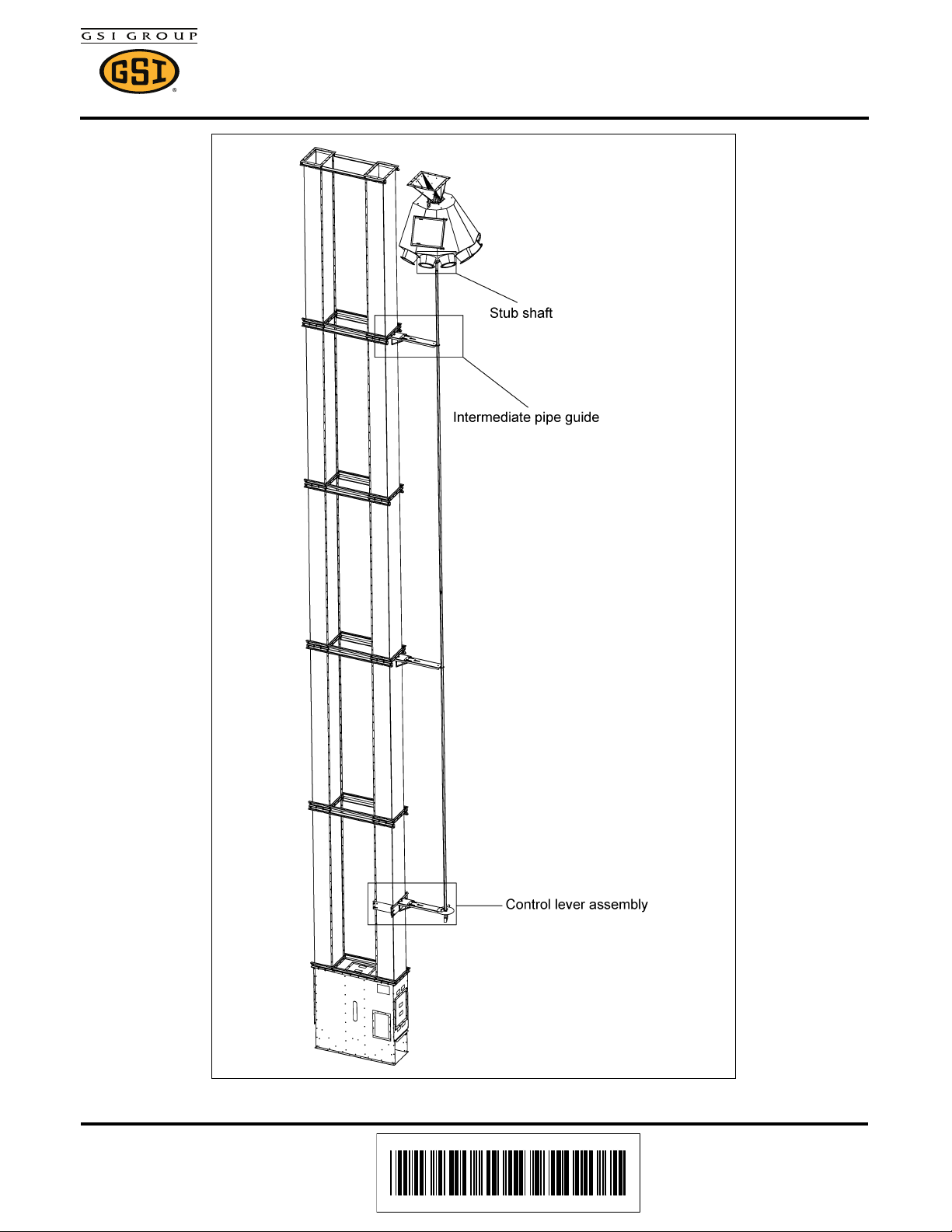
Figure 1 Overall View
Date: 03-24-11 PNEG-1793
Printed in the U.S.A.
Copyright © 2011 by GSI Group
www.gsiag.com
Page 1 of 8
Page 2
Distributor Pipe Control - Farm/Commercial
Cable clamp
Cable (not
supplied)
Install cable as pipe is installed.
It runs down center of pipe.
Pipe control stub
shaft (DPC0003)
5" Pipe coupler (DPC0012)
5/16" x 1-3/4"
Spring pin (S-8397)
5/16" x 1-3/4"
Spring pin (S-8397)
20' Long control pipe (DPC0001)
5/16"-18 x 1" Bolts (S-1196)
and 5/16" flange nuts (S-3611)
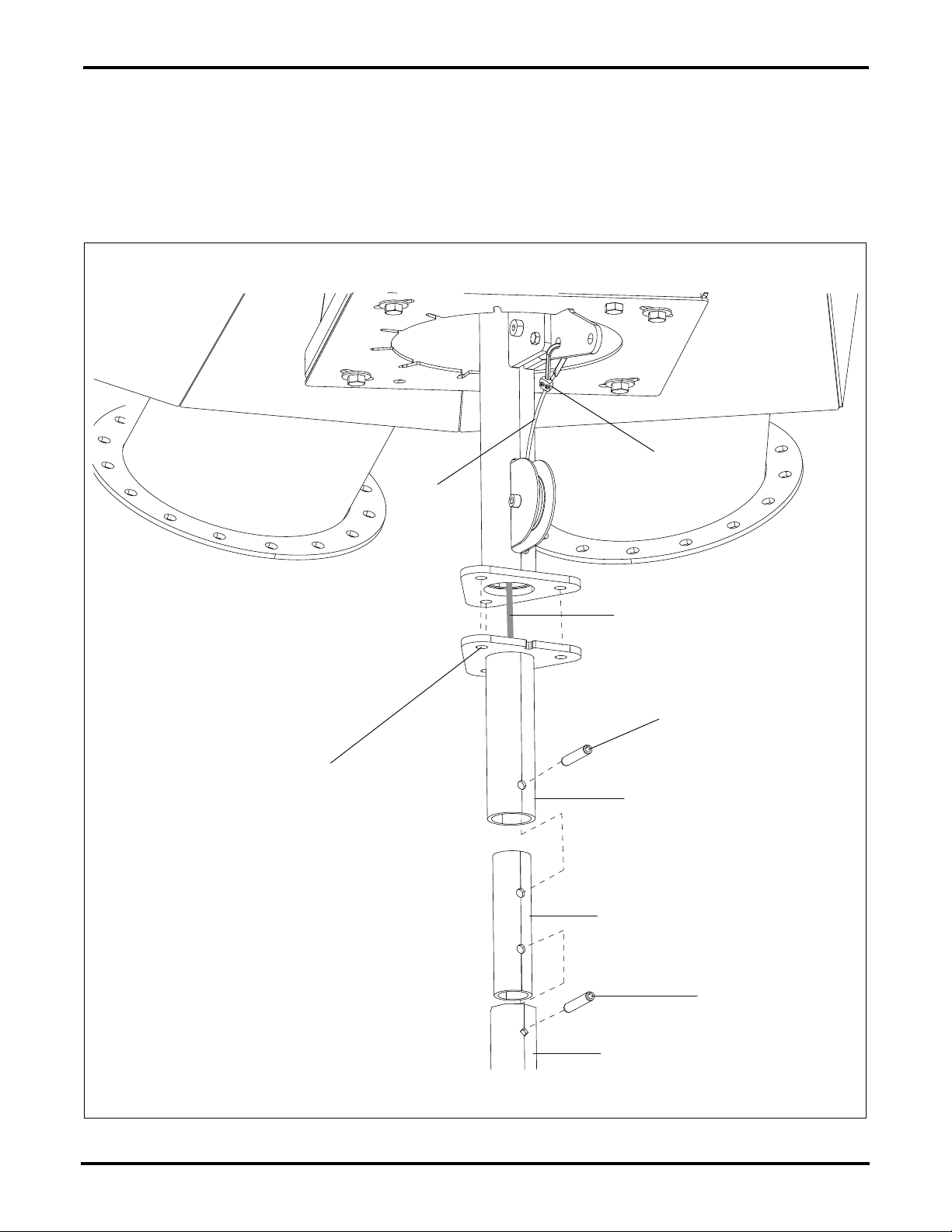
1. Bolt stub shaft (DPC0003) to the index tube assembly, aligning notch in flange with sheave and using
three (3) 5/16" x 1" HHCS bolts (S-1196) and three (3) 5/16" flange nuts (S-3611).
2. Using the 5/16" x 1-3/4" roll pins (S-8397), connect the 5" pipe coupler (DPC0012) to the stub shaft.
3. Install cable (not included) to connect the distributor index assembly to the control lever. Secure the
cable to the distributor index assembly as shown using a cable clamp. Run the cable down the center
of each piece of pipe as they are attached. (See Figure 2.)
Figure 2 Stub Shaft and Cable
Page 2 of 8 PNEG-1793
Page 3
Distributor Pipe Control - Farm/Commercial
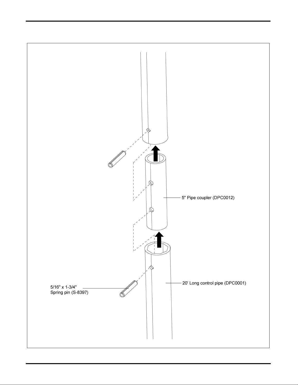
4. Install the 20' control pipes (DPC0001) using the supplied hardware 5/16" x 1-3/4" roll pins (S-8397)
and 5" pipe couplers (DPC0012). (See Figure 3.)
Figure 3 Pipe Connections
PNEG-1793 Page 3 of 8
Page 4

Distributor Pipe Control - Farm/Commercial
5. Assemble intermediate guide assemblies by attaching the inner mount pipe control bracket
(DPC0005) to the outer pipe guide bracket using two (2) 3/8" x 3/4" bolts (S-7105), two (2)
3/8" flat washers (S-248) and two (2) 3/8" standard flange nuts (S-10028). Use one 3/8" x 3/4" bolt
(S-7105) and one 3/8" flat washer (S-248) to secure the inner mount pipe control bracket (DPC0005)
to the pipe control bracket brace (DPC0021). Secure the bottom of the pipe control bracket brace
(DPC0021) to the middle slot on the outer pipe guide bracket (DPC0018) with one 3/8" x 3/4"
bolt (S-7105), one 3/8" flat washer (S-248) and one 3/8" standard flange nut (S-10028).
(See Figure 4.)
Figure 4 Pipe Control Guide Brackets (This is the same assembly for both
intermediate and control lever assemblies.)
Page 4 of 8 PNEG-1793
Page 5

Distributor Pipe Control - Farm/Commercial
6. Attach the inner mount pipe control bracket (DPC0005) to the trunking using two (2) 3/8" x 1"
HHCS bolts (S-7469) and two (2) 3/8" large flange nuts (S-968), as shown in Figure 5.
7. Attach the control pipe to the intermediate guides with a 1/4" x 1-3/4" x 3" U-bolt (S-10145) and
four (4) 1/4" flange nuts (S-7215). (See Figure 5.)
Figure 5 Intermediate Guide to Trunking
PNEG-1793 Page 5 of 8
Page 6

Distributor Pipe Control - Farm/Commercial
8. Assemble the inner mount pipe control bracket (DPC0005) to the pipe control bracket brace
(DPC0021) using the same method as the intermediate guide assembly. (See Figure 4 on Page 4.)
Attach the eight (8) hole index plate (DPC0010) to the outer pipe guide bracket (DPC0018)
using 3/8" x 3/4" bolt (S-7105), 3/8" flat washer (S-248) and 3/8" flange nut (S-10028).
9. Assemble the clamp band as shown by fastening the clamp rod weldment (DSP16003) to the clamp
band (DSP16002) using 1/2" flange nuts (S-8506) onto the rod ends. Attach the index plate mount
angle (DPC0009) to the front of the clamp bands (DSP16002) with 3/8" x 1" bolts (S-7469),
3/8" flat washers (S-248) and 3/8" flange nuts (S-10028).
10. Attach the control lever assembly to the trunking using two (2) 3/8" x 1" bolts (S-7469),
3/8" flat washers (S-248) and 3/8" flange nuts (S-10028) and secure to the guide using
1/4" x 3/4" x 3" U-bolt (S-10145) and four (4) 1/4" flange nuts (S-7215). (See Figure 6.)
Figure 6 Control Lever Assembly to Trunking
Page 6 of 8 PNEG-1793
Page 7

Distributor Pipe Control - Farm/Commercial
Cable
Cable clamp
5/16"-18 x 1-1/2"
Shoulder bolt
(S-10144)
Guard (DPC0022)
Pull
5/16" Flange
nut (S-3611)
Control handle
(DPC0016)
1/4" x 1-3/4" x 3"
U-Bolt (S-10145)
5/16" x 1-3/4"
Spring pin (S-8397)
11. Cut last section of piping to desired length and drill hole for 5/16" roll pin. Guide the last section of
control pipe through the index plate (DPC0010).
12. Attach the pipe control lever assembly (DPC0015) to the bottom of the pipe using a 5/16" x 1-3/4"
roll pin (S-8397).
13. Remove guard (DPC0022) from the control handle assembly. Guide cable through end of control
handle (DPC0016). Pull cable down with enough tension to keep cable taught, but not enough
to pull down on the distributor index assembly. Secure cable with cable clamp (not supplied).
Replace guard (DPC0022). (See Figure 7.)
Figure 7 Bottom Cable
PNEG-1793 Page 7 of 8
Page 8

Distributor Pipe Control - Farm/Commercial
14. Install the position indicator (DPC0017) to the pipe using the U-bolt (S-10145) and 1/4" flange
nuts (S-7215). (See Figure 8.)
Figure 8 Pipe Control Lever and Position Indicator
15. Apply the provided numbered decals as desired to denote the distributor spout position.
Page 8 of 8 PNEG-1793
 Loading...