

Page 1

PNEG-1787
42'-135' “X” Series Sidewall Stair
and Eave Platform
Assembly Instructions
PNEG-1787
Date: 02-16-11
Page 2

2 PNEG-1787 42'-135' “X” Series Sidewall Stair and Eave Platform
Page 3

Table of Contents
Contents
Chapter 1 Introduction ..........................................................................................................................................4
Chapter 2 Safety .....................................................................................................................................................5
Safety Guidelines .................................................................................................................................. 5
General Safety Statement ..................................................................................................................... 6
Safety Instructions ..................... ... .... .......................................... ... ... ..................................................... 7
Safety Sign-Off Sheet ........................................................................................................................... 9
Proper Storage of Grain Bin/Silo Materials Prior to Construction ....................................................... 10
Chapter 3 Decals ..................................................................................................................................................11
Chapter 4 72'-135' Assembly Instructions .............................. ...........................................................................14
72'-135' Sidewall Stair Bracket Assembly ........................................................................................... 15
72'-135' Sidewall Stair Sub-assemblies .............................................................................................. 16
“X” Series Top Sidewall Stair Assembly ..........................................................................................16
“X” Series Standard Stair Assembly ................................................................................................17
Sidewall Stair Bracket Assembly - Reverse ........................................................................................ 18
72'-135' Sidewall Stair Sub-assemblies - Reverse .............................................................................. 19
“X” Series Top Sidewall Stair Assembly - Reverse .........................................................................19
“X” Series Standard Stair Assembly - Reverse ...............................................................................20
72'-135' Eave Platform and Manway Guard Sub-assemblies ............................................................. 21
“X” Series Platform Assembly ..........................................................................................................21
“X” Series Platform Assembly - Reverse ........ .................................................................................23
Platform Assembly on Bin Wall ......................................................... ..............................................25
72'-135' Sidewall Stair, Eave Platform, Manway Guard and Roof Stair Interaction ............................ 26
72'-135' Sidewall Stair, Eave Platform, Manway Guard and Roof Stair Interaction - Reverse ........... 27
“X” Series Manway Guard Package (STX-0087-REV) .................................................................... 27
72'-135' Assembly and Interaction of All Stair Components ............................................................... 28
Top and Standard Assembly to Wall Brackets (STX-0061 and STX-0062) ....................................28
Assembly to Platform (STX-0061) ..................................... ..............................................................29
72'-135' “X” Series Platform Assembly - Sidewall Stairs Only ............................................................ 30
Assembly and Interaction of All Stair Components ............................................................................. 34
Stair Wall Bracket Layout Assembly on Bin Wall (STX-0036, STX-0023 and STX-0022) ..............34
Chapter 5 42'-60' Assembly Instructions .................................... .......................................................................35
42'-60' Sidewall Stair Bracket Assembly ............................................................................................. 36
42'-60' Sidewall Stair Sub-assemblies ................................................................................................ 37
“X” Series Top Sidewall Stair Assembly ..........................................................................................37
“X” Series Standard Stair Assembly ................................................................................................38
Sidewall Stair Bracket Assembly - Reverse ........................................................................................ 39
42'-60' Sidewall Stair Sub-assemblies - Reverse ................................................................................ 40
“X” Series Top Stair Assembly - Reverse ........................................................................................40
“X” Series Standard Stair Assembly - Reverse ...............................................................................41
42'-60' Eave Platform Sub-assembly .................................................................................................. 42
42'-60' Complete Form and Roof Stair Interaction .............................................................................. 45
42'-60' Sidewall Stair, Eave Platform, Manway Guard and Roof Stair
Interaction Sub-assembly .................................... ................... .................... ................... ...................... 46
42'-60' Eave Platform Sub-assembly - Reverse .................................................................................. 47
42'-60' Sidewall Stair, Eave Platform, Manway Guard and Roof Stair
Interaction Sub-assembly - Reverse ................................ ... ... .... ... ... ... ................................................ 51
Chapter 6 Warranty ..............................................................................................................................................53
PNEG-1787 42'-135' “X” Series Sidewall Stair and Eave Platform 3
Page 4

1. Introduction
READ THIS MANUAL carefully to learn how to properly use and install equipment. Failure to do so could
result in personal injury or equipment damage.
INSPECT the shipment immediately upon arrival. The customer is responsible for ensuring that all
quantities are correct. The customer should report and note any damage or shortage on the bill of
lading to justify their claim to the transport company.
THIS MANUAL SHOULD BE CONSIDERED a permanent part of your equipment and should be easily
accessible when needed.
This warranty provides you the assurance that the company will back its products when defects appear
within the warranty period. In some circumstances, the company also provides field improvements, often
without charge to the customer, even if the product is out of warranty. Should the equipment be abused,
or modified to change its performance beyond the factory specifications, the warranty will become void
and field improvements may be denied.
4 PNEG-1787 42'-135' “X” Series Sidewall Stair and Eave Platform
Page 5
2. Safety
DANGER
WARNING
CAUTION
NOTICE
This is the safety alert symbol. It is used to alert you
to potential personal injury hazards. Obey all safety
messages that follow this symbol to avoid possible
injury or death.
WARNING indicates a hazardous situation which, if not
avoided, could result in death or serious injury.
CAUTION, used with the safety alert symbol, indicates a
hazardous situation which, if not avoided, could result in
minor or moderate injury.
NOTICE is used to address practices not related to
personal injury.
DANGER indicates a hazardous situation which, if not
avoided, will result in death or serious injury.
Safety Guidelines
This manual contains information that is important for you, the owner/operator, to know and understand.
This information relates to protecting personal safety and preventing equipment problems. It is the
responsibility of the owner/operator to inform anyone operating or working in the area of this equipment
of these safety guidelines. To help you recognize this information, we use the symbols that are defined
below. Please read the manual and pay attention to these sections. Failure to read this manual and its
safety instructions is a misuse of the equipment and may lead to serious injury or death.
PNEG-1787 42'-135' “X” Series Sidewall Stair and Eave Platform 5
Page 6
2. Safety
This product has sharp edges, which may cause serious injury. To avoid injury, handle
sharp edges with caution and always use proper protective clothing and equipment.
General Safety Statement
Our foremost concern is your safety and the safety of others associated with this equipment. Th is manual
is to help you understand safe operating procedures and some problems which may be encountered by
the operator and other personnel.
As owner and/or operator, you are responsible to know what requirements, hazards and precautions exist
and inform all personnel associated with the equipment or in the area. Safety precautions may be required
from the personnel. Avoid any alterations to the equipment, which may produce a very dangerous
situation, where SERIOUS INJURY or DEATH may occur.
You should consider the location of the bin site relative to power line locations or electrical transmission
equipment. Contact your local power company to review your installation plan or for information
concerning required equipment clearance. Clearance of portable equipment that may be taken to the bin
site should also be reviewed and considered. Any electrical control equipment in contact with the bin
should be properly grounded and installed in accordance with National Electric Code provisions and other
local or national codes.
This product is intended for the use of grain storage only. Any other use is a misuse of the product.
Sidewall bundles or sheets must be stored in a safe manner. The safest method of storing sidewall
bundles is laying horizontally with the arch of the sheet upward, like a dome. Sidewall sheets stored on
edge must be secured so that they cannot fall over and cause injury. Use care when handling and moving
sidewall bundles.
Personnel operating or working around equipment should read this manual. This manual must be
delivered with equipment to its owner. Failure to read this manual and its safety instructions is a misuse
of the equipment.
6 PNEG-1787 42'-135' “X” Series Sidewall Stair and Eave Platform
Page 7
2. Safety
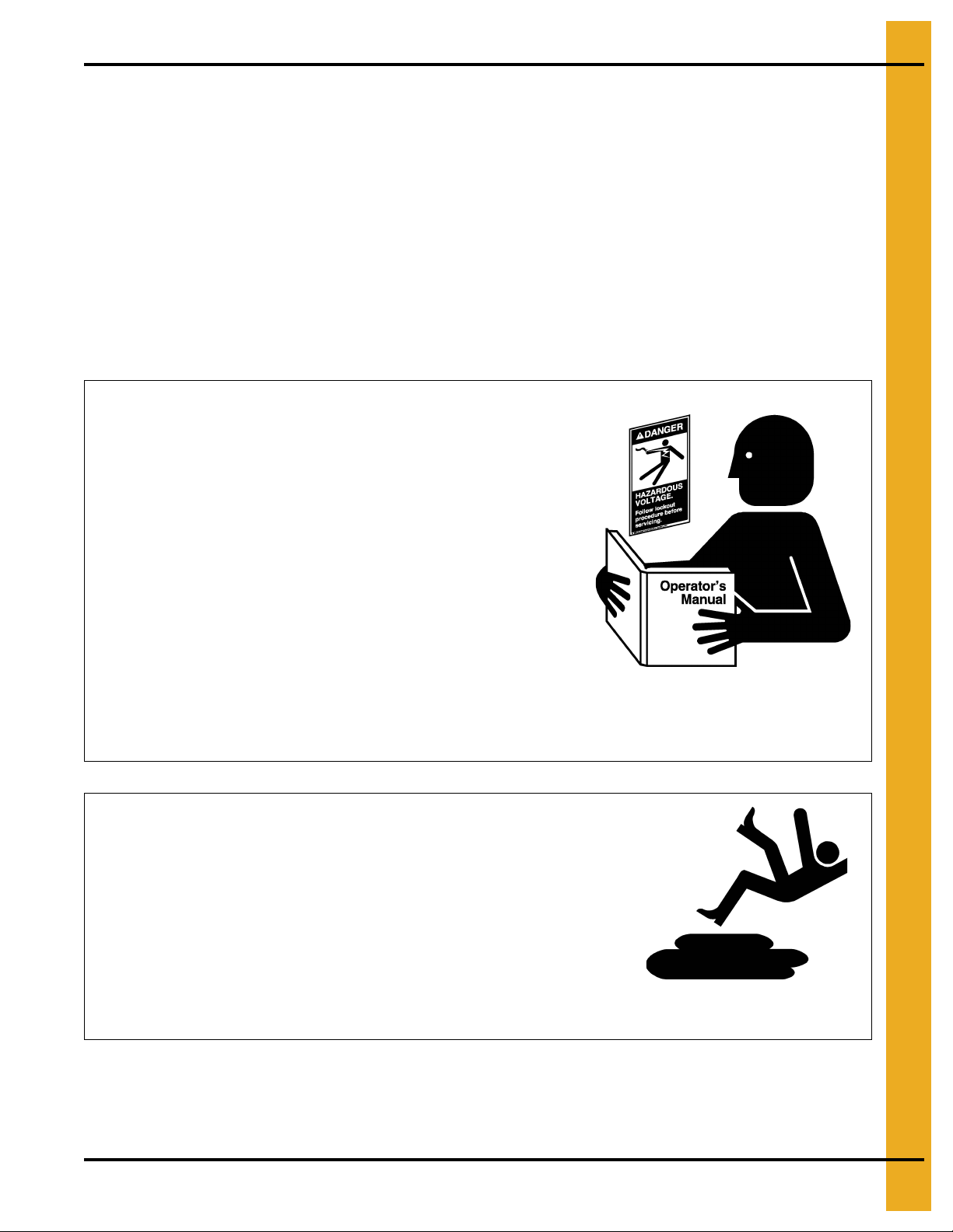
Follow Safety Instructions
Carefully read all safety messages in this manual and
safety signs on your machine. Keep signs in good
condition. Replace missing or damaged safety signs. Be
sure new equipment components and repair parts include
the current safety signs. Replacement safety signs are
available from the manufacturer.
Learn how to operate the machine and how to use controls
properly. Do not let anyone operate without instruction.
Keep your machinery in proper working condition.
Unauthorized modifications to the machine may impair
the function and/or safety and affect machine life.
If you do not understand any part of this manual or need
assistance, contact your dealer.
Read and Understand Manual
Practice Safe Maintenance
Understand service procedures before doing work. Keep area
clean and dry.
Never lubricate, service, or adjust machine while it is in operation.
Keep hands, feet and clothing away from rotating parts.
Keep all parts in good condition and properly installed. Fix
damage immediately . Replace worn or broken p arts. Remove any
built up grease oil and debris.
Maintain Equipment
and Work Area
Safety Instructions
Our foremost concern is your safety and the safety of others associated with this equipment. We want to
keep you as a customer. This manual is to help you understand safe operating procedures and some
problems which may be encountered by the operator and other personnel.
As owner and/or operator, it is your responsibility to know what requirements, hazards and precautions
exist, and to inform all personnel associated with the equipment or in the area. Safety precautions may be
required from the personnel. Avoid any alterations to the equipment. Such alterations may produce a very
dangerous situation where SERIOUS INJURY or DEATH may occur.
This equipment shall be installed in accordance with the current installation codes and applicable
regulations which should be carefully followed in all cases. Authorities having jurisdiction should be
consulted before installations are made.
PNEG-1787 42'-135' “X” Series Sidewall Stair and Eave Platform 7
Page 8
2. Safety
Prepare for Emergencies
Be prepared if fire starts.
Keep a first aid kit and fire extinguisher handy.
Keep emergency numbers for doctors, ambulance service,
hospital and fire department near your telephone.
Keep Emergency Equipment
Quickly Accessible
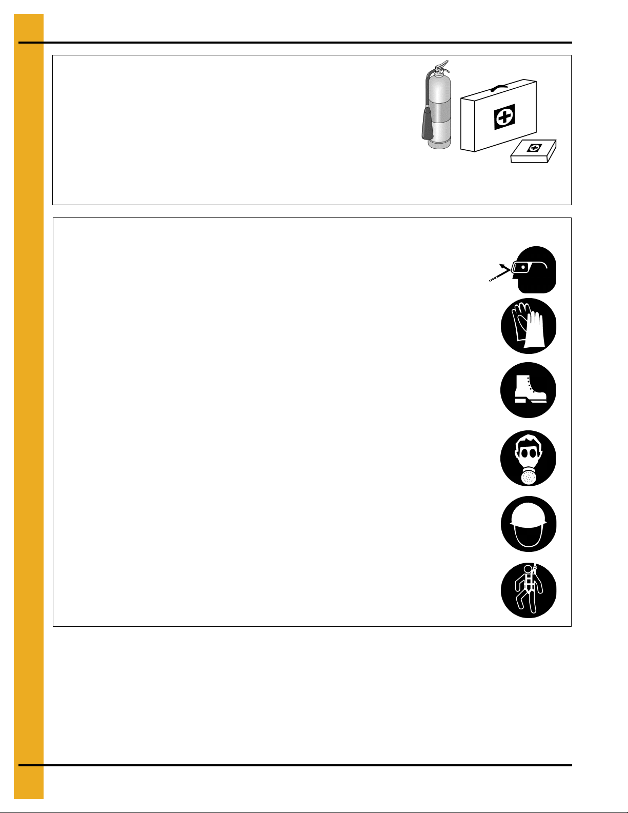
Wear Protective Clothing
Wear close fitting clothing and safety equipment appropriate
to the job.
Remove all jewelry.
Long hair should be tied up and back.
Safety glasses should be worn at all times to protect eyes
from debris.
Wear gloves to protect your hands from sharp edges on
plastic or steel parts.
Wear steel toe boots to help protect your feet from falling
debris. Tuck in any loose or dangling shoe strings.
A respirator may be needed to prevent breathing potentially
toxic fumes and dust.
Wear hard hat to help protect your head.
Wear appropriate fall protection equipment when working at
elevations greater than six feet (6').
Eye Protection
Gloves
Steel Toe Boots
Respirator
Hard Hat
Fall Protection
8 PNEG-1787 42'-135' “X” Series Sidewall Stair and Eave Platform
Page 9
2. Safety
Safety Sign-Off Sheet
As a requirement of O.S.H.A., it is necessary for the employer to train the employee in the safe operating
and safety procedures for this equipment. This sign-off sheet is provided for your convenience and
personal record keeping. All unqualified persons are to stay out of the work area at all times. It is strongly
recommended that another qualified person who knows the shut down procedure be in the area in the
event of an emergency.
Date Employee Name Supervisor Name
PNEG-1787 42'-135' “X” Series Sidewall Stair and Eave Platform 9
Page 10

2. Safety
Proper Storage of Grain Bin/Silo Materials Prior to Construction
Wet storage stain (rust) will develop when closely packed bundles of galvanized material, such as sidewall
and roof sheets, have moisture present. Inspect roof and sidewall bundles on arrival for any moisture. If
moisture is present, it must not be allowed to remain between the she ets. Separate the sheets or panels
immediately and wipe them down. Spray with a light oil or diesel fuel.
If possible, sidewall bundles, roof sheets and other closely packed galvanized materials should be stored
in a dry, climate controlled building. If outdoor storage is unavoidable, the materials should be stored so
that they are raised above the ground and vegetation. Any stacking an d spacing mat erials sho uld not be
corrosive or wet. Be sure to protect materials from the weather, but permit air movement around the
bundles if possible.
Storing roof bundles and sidewall sheets at a slight incline can also help minimize the presence of
moisture. Storing the bundles with the center of the dome up (like an arch) is one option for minimizing
moisture during storage. Sidewall bundles can also be stored on edge but must be secured so that they
do not fall over and cause injury.
If “white rust” or “wet storage stain” occurs, contact the manufacturer imme diately about ways to minimize
the adverse effect upon the galvanized coating.
10 PNEG-1787 42'-135' “X” Series Sidewall Stair and Eave Platform
Page 11
3. Decals
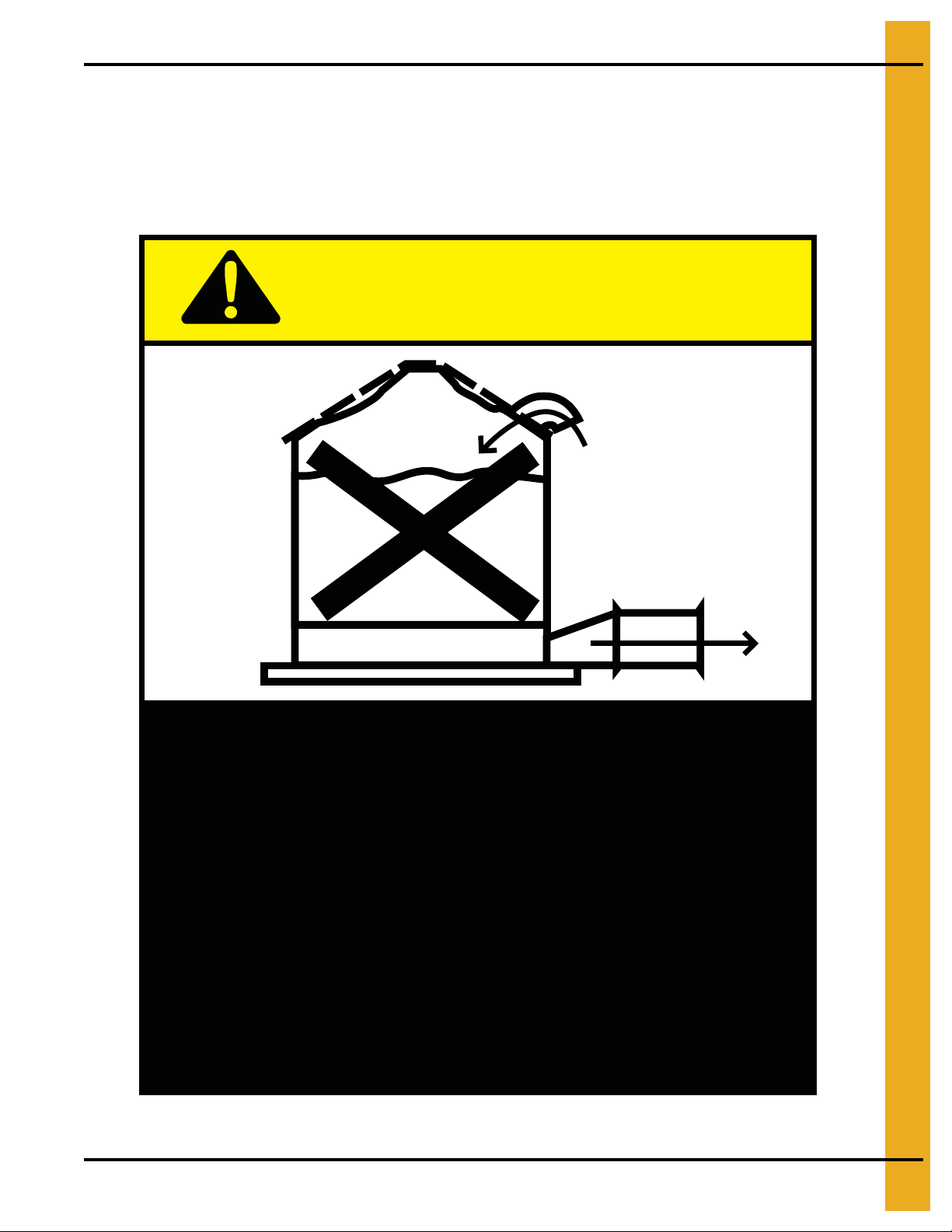
Excessive vacuum (or pressure) may
damage roof. Use positive aeration
system. Make sure all roof vents are
open and unobstructed. Start roof
fans when supply fans are started.
Do not operate when conditions exist
that may cause roof vent icing.
DC-969
CAUTION!
The manufacturer does not warrant any roof damage caused by excessive vacuum or internal
pressure from fans or other air moving systems. Adequate ventilation and/or “makeup air” devices
should be provided for all powered air handling systems. The manufacturer does n ot recommend
the use of downward flow systems (suction). Severe roof damage can result fro m any blockage of
air passages. Running fans during high humidity/cold weather conditions can cause air exhaust
or intake ports to freeze.
PNEG-1787 42'-135' “X” Series Sidewall Stair and Eave Platform 11
Page 12
3. Decals
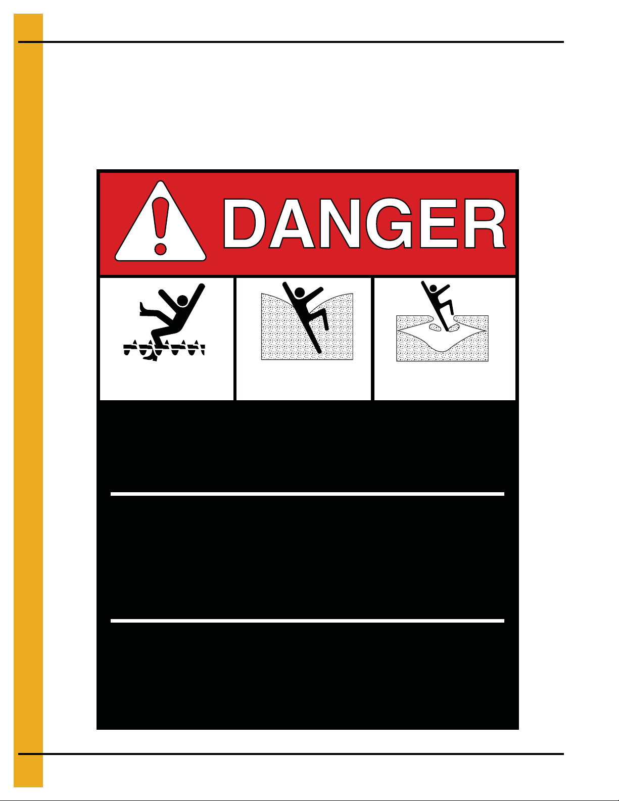
Rotating flighting will
kill or dismember.
Flowing material will
trap and suffocate.
Crusted material will
collapse and suffocate.
Keep clear of all augers.
DO NOT ENTER this bin!
Failure to heed these
warnings will result in
serious injury or death.
If you must enter the bin:
1. Shut off and lock out all power.
2. Use a safety harness and safety line.
3. Station another person outside the bin.
4. Avoid the center of the bin.
5. Wear proper breathing equipment or respirator.
DC-GBC-1A
ATTENTION: The decal shown below should be present on the outside of the door cover of the 2 ring,
24" porthole door cover and the roof manway cover. If a decal has been damaged or is missing in any of
these locations, contact the manufacturer for a free replacement decal.
GSI Decals
1004 E. Illinois St.
Assumption, IL. 62510
Phone: 1-217-226-4421
12 PNEG-1787 42'-135' “X” Series Sidewall Stair and Eave Platform
Page 13
3. Decals
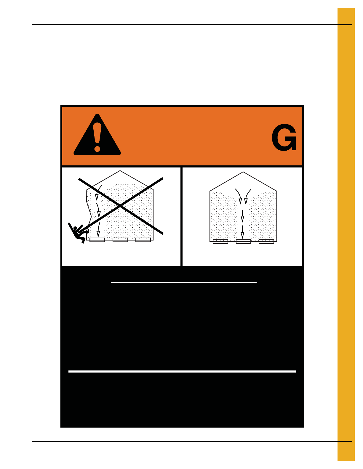
Failure to heed these warnings
could result in serious injury, death,
structural damage or collapse of tank.
1. Use CENTER FLOOR OUTLET ONLY until NO grain
remains above this outlet.
2. Side floor outlets to be used ONLY when above
condition is satisfied.
3. Lock all side floor outlets to avoid accidental
premature use.
4. See manufacturers instructions for proper use of
factory supplied sidedraw (wall) discharge systems.
UNLOADING INSTRUCTIONS:
DC-GBC-2A
WARNIN
DON’T
DO
ATTENTION: The decal shown below should be present on the outside of the door cover of the 2 ring,
24" porthole door cover and the roof manway cover. If a decal has been damaged or is missing in any of
these locations, contact the manufacturer for a free replacement decal.
GSI Decals
1004 E. Illinois St.
Assumption, IL. 62510
Phone: 1-217-226-4421
PNEG-1787 42'-135' “X” Series Sidewall Stair and Eave Platform 13
Page 14
4. 72'-135' Assembly Instructions
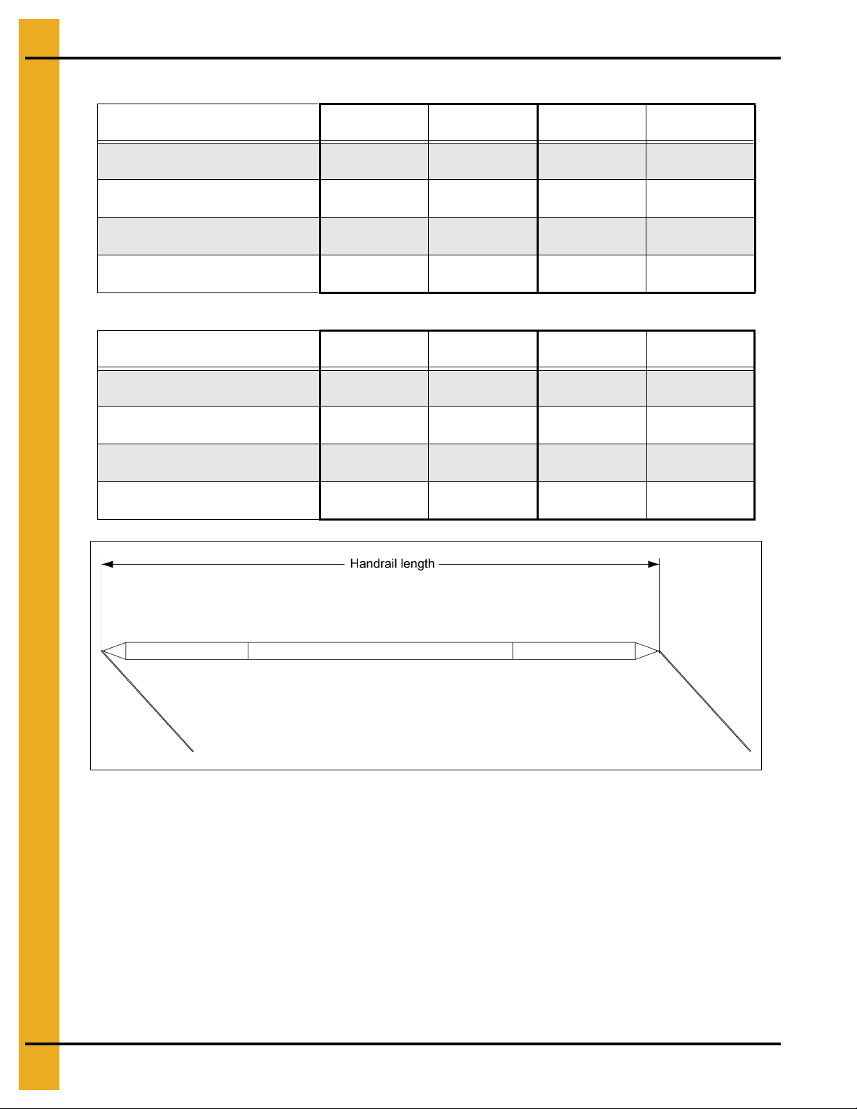
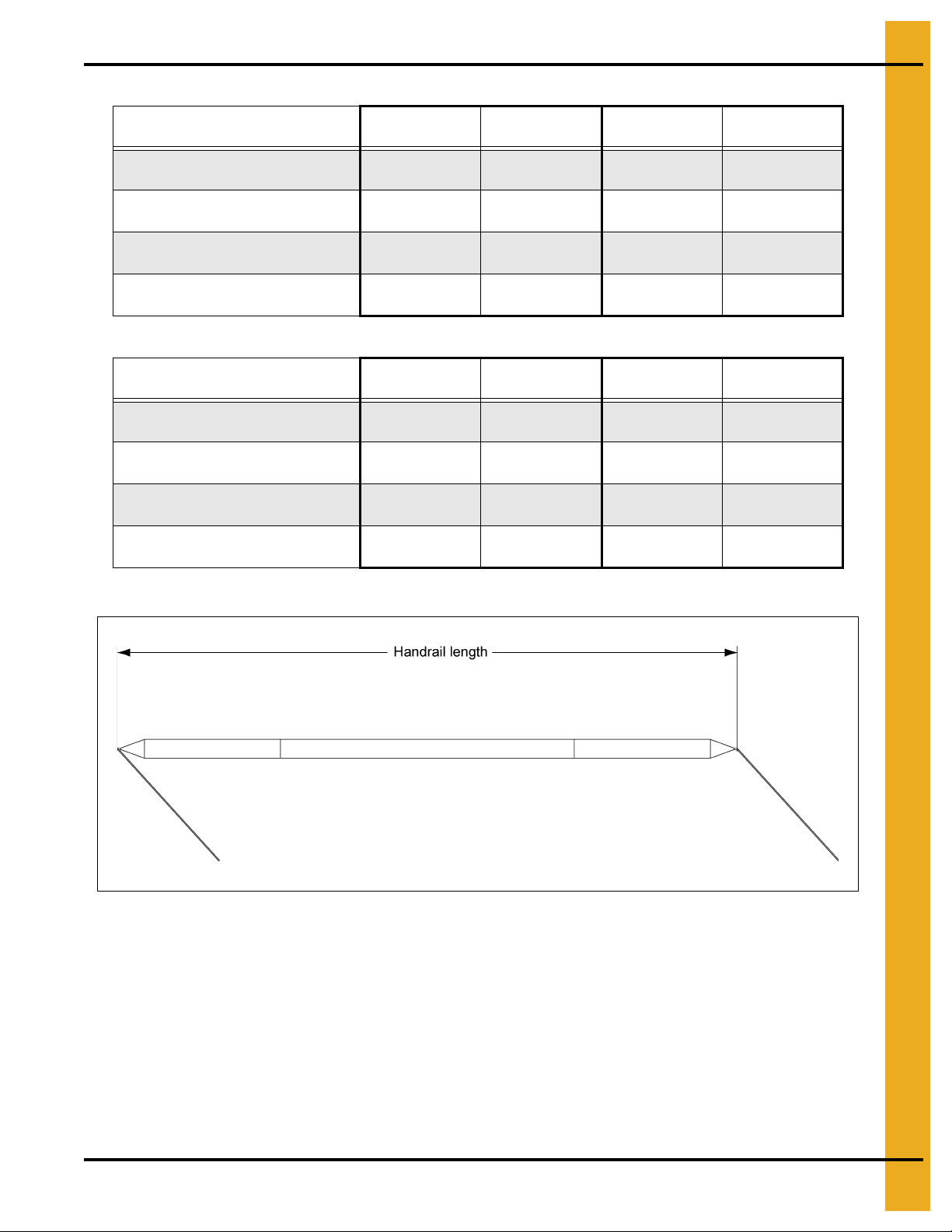
Sidewall Stair Handrail Lengths and Part Numbers
Description Handrail Length 105' Versions Handrail Length 135' Versions
Top Section Handrail Outside 49.062" STX-0030 48.562" STX-0096
Top Section Handrail Inside 48.187" STX-0031 48.062" STX-0093
Standard Section Handrail Outside 50.936" STX-0032 50.436" STX-0094
Standard Section Handrail Inside 49.687" STX-0033 49.562" STX-0095
Description Handrail Length 90' Versions Handrail Length 72'-78' Versions
Top Section Handrail Outside 49.452" STX-0126 50.125" STX-0130
Top Section Handrail Inside 48.360" STX-0127 48.500" STX-0131
Standard Section Handrail Outside 51.326" STX-0128 51.854" STX-0132
Standard Section Handrail Inside 49.860" STX-0129 50.000" STX-0133
14 PNEG-1787 42'-135' “X” Series Sidewall Stair and Eave Platform
Page 15
72'-135' Sidewall Stair Bracket Assembly
4. 72'-135' Assembly Instructions
Figure 4A
PNEG-1787 42'-135' “X” Series Sidewall Stair and Eave Platform 15
Page 16
4. 72'-135' Assembly Instructions
T op section handrail inside
(See chart on Page 14 for
part numbers.)
Top section handrail outside
(See chart on Page 14 for
part numbers.)
Stair bracket assembly
(See Page 15 for part
numbers.)
72'-135' Sidewall Stair Sub-assemblies
“X” Series Top Sidewall Stair Assembly
Figure 4B
16 PNEG-1787 42'-135' “X” Series Sidewall Stair and Eave Platform
Page 17
4. 72'-135' Assembly Instructions
Standard section handrail
inside (See chart on
Page 14 for part numbers.)
Standard section handrail
outside (See chart on
Page 14 for part numbers.)
Stair bracket assembly
(See Page 15 for part
numbers.)
72'-135' Sidewall Stair Sub-assemblies (Continued)
“X” Series Standard Stair Assembly
PNEG-1787 42'-135' “X” Series Sidewall Stair and Eave Platform 17
Figure 4C
Page 18
4. 72'-135' Assembly Instructions
Sidewall Stair Bracket Assembly - Reverse
Figure 4D
18 PNEG-1787 42'-135' “X” Series Sidewall Stair and Eave Platform
Page 19

4. 72'-135' Assembly Instructions
T op section handrail outside
(See chart on Page 14 for
part numbers.)
T op section handrail inside
(See chart on Page 14 for
part numbers.)
Stair bracket assembly
(See Page 18 for part
numbers.)
72'-135' Sidewall Stair Sub-assemblies - Reverse
“X” Series Top Sidewall Stair Assembly - Reverse
PNEG-1787 42'-135' “X” Series Sidewall Stair and Eave Platform 19
Figure 4E
Page 20

4. 72'-135' Assembly Instructions
Standard section handrail
outside (See chart on Page 14
for part numbers.)
Standard section handrail
inside (See chart on
Page 14 for part numbers.)
Stair bracket assembly
(See Page 18 for part
numbers.)
72'-135' Sidewall Stair Sub-assemblies - Reverse (Continued)
“X” Series Standard Stair Assembly - Reverse
Figure 4F
20 PNEG-1787 42'-135' “X” Series Sidewall Stair and Eave Platform
Page 21

4. 72'-135' Assembly Instructions
72'-135' Eave Platform and Manway Guard Sub-assemblies
“X” Series Platform Assembly
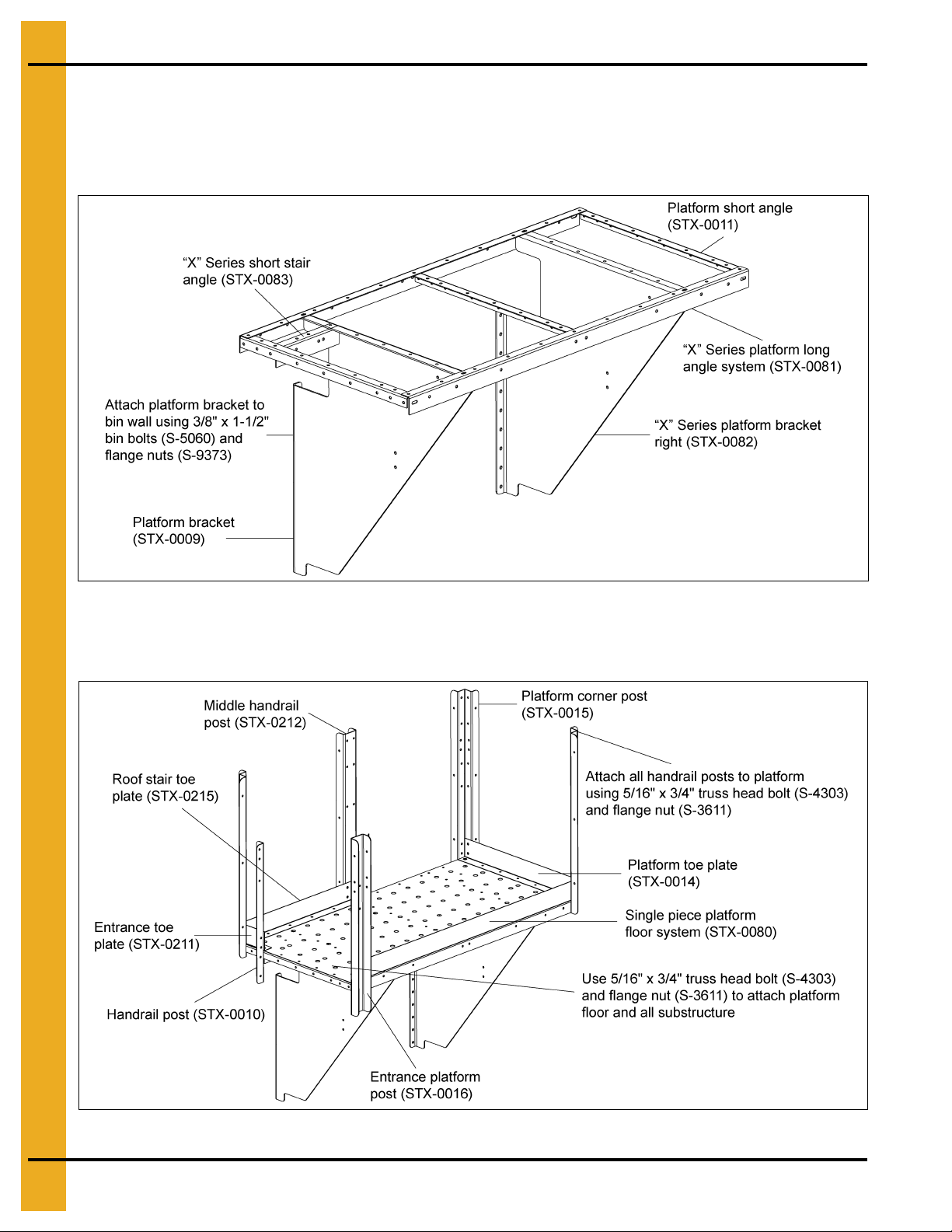
1. Figure 4G shows the assembly of the platform supports. Use 5/16" hardware at all the connection
points. (The bin wall and platform floor is hidden for clarity. Platform floor will have to be attached
at the same time as support angles.)
Figure 4G
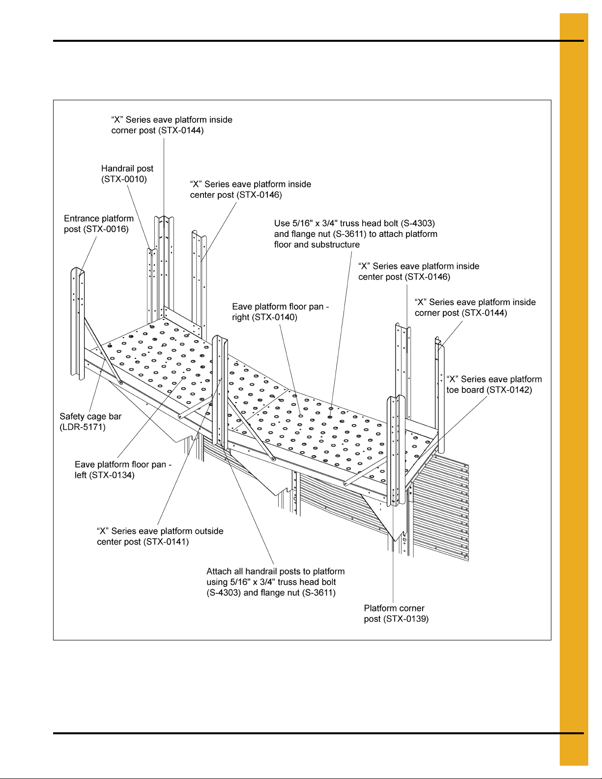
2. Figure 4H shows the assembly of the platform post, handrail post, toe plate, platform corner post and
platform floor system. This must all be assembled at the same time using 5/16" hardware.
Figure 4H
PNEG-1787 42'-135' “X” Series Sidewall Stair and Eave Platform 21
Page 22

4. 72'-135' Assembly Instructions
72'-135' Eave Platform and Manway Guard Sub-assemblies
(Continued)
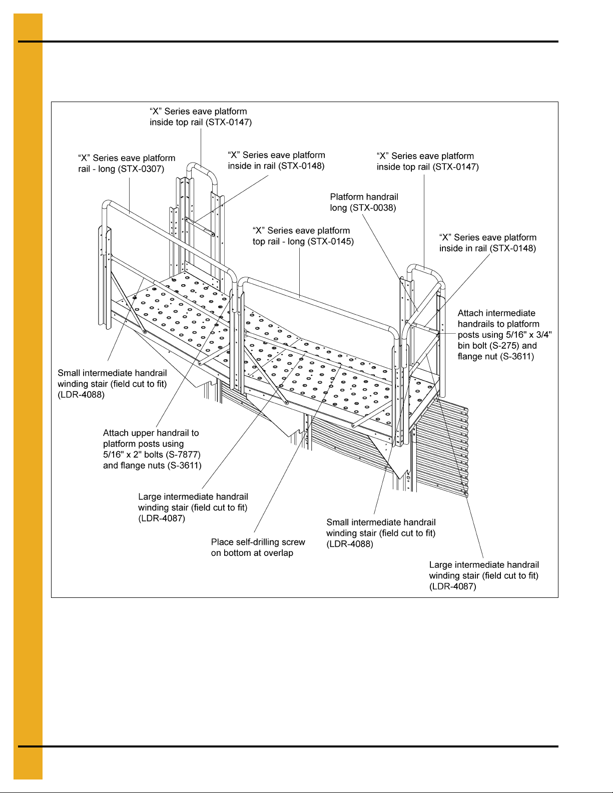
3. Figure 4I shows the assembly of the platform handrails. These must also be attached using
5/16" hardware.
Figure 4I
22 PNEG-1787 42'-135' “X” Series Sidewall Stair and Eave Platform
Page 23

4. 72'-135' Assembly Instructions
72'-135' Eave Platform and Manway Guard Sub-assemblies
(Continued)
“X” Series Platform Assembly - Reverse
1. Figure 4J shows the assembly of the platform supports. Use 5/16" hardware at all the connection
points. (The bin wall and platform floor is hidden for clarity. Platform floor will have to be attached
at the same time as support angles.)
Figure 4J
2. Figure 4K shows the assembly of the platform toe plate, handrail post, platform post and platform
floor system. This must all be assembled at the same time using 5/16" hardware.
Figure 4K
PNEG-1787 42'-135' “X” Series Sidewall Stair and Eave Platform 23
Page 24

4. 72'-135' Assembly Instructions
72'-135' Eave Platform and Manway Guard Sub-assemblies
(Continued)
3. Figure 4L shows the assembly of the platform handrails. These must also be attached using
5/16" hardware.
Figure 4L
24 PNEG-1787 42'-135' “X” Series Sidewall Stair and Eave Platform
Page 25

4. 72'-135' Assembly Instructions
72'-135' Eave Platform and Manway Guard Sub-assemblies
(Continued)
Platform Assembly on Bin Wall
Figure 4M
Figure 4N
PNEG-1787 42'-135' “X” Series Sidewall Stair and Eave Platform 25
Page 26
4. 72'-135' Assembly Instructions
72'-135' Sidewall Stair, Eave Platform, Manway Guard and Roof
Stair Interaction
Figure 4O
26 PNEG-1787 42'-135' “X” Series Sidewall Stair and Eave Platform
Page 27

4. 72'-135' Assembly Instructions
72'-135' Sidewall Stair, Eave Platform, Manway Guard and Roof
Stair Interaction - Reverse
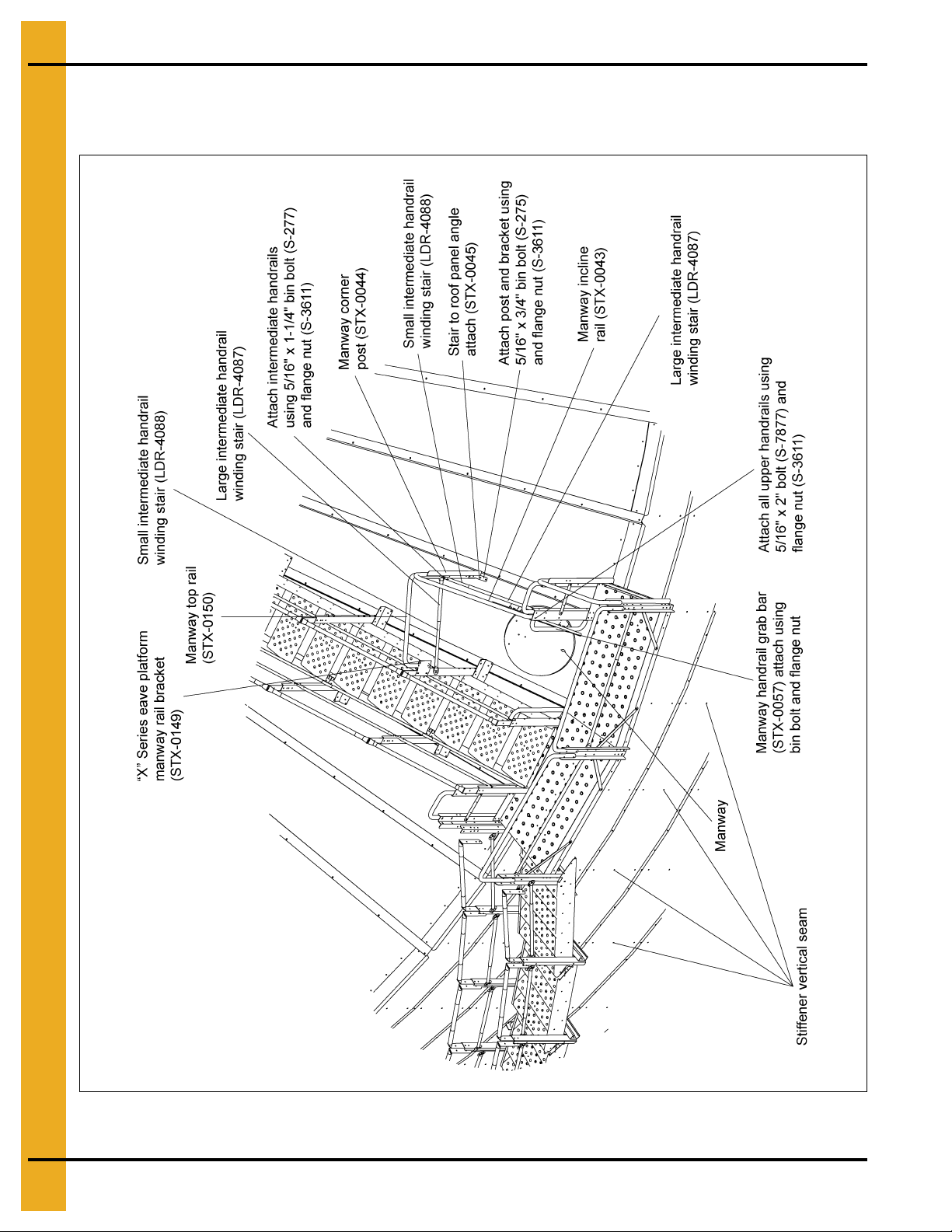
“X” Series Manway Guard Package (STX-0087-REV)
Figure 4P
PNEG-1787 42'-135' “X” Series Sidewall Stair and Eave Platform 27
Page 28

4. 72'-135' Assembly Instructions
72'-135' Assembly and Interaction of All Stair Components
Top and Standard Assembly to Wall Brackets (STX-0061 and STX-0062)
Figure 4Q
28 PNEG-1787 42'-135' “X” Series Sidewall Stair and Eave Platform
Page 29

4. 72'-135' Assembly Instructions
72'-135' Assembly and Interaction of All Stair Components
(Continued)
Assembly to Platform (STX-0061)
Figure 4R
PNEG-1787 42'-135' “X” Series Sidewall Stair and Eave Platform 29
Page 30
4. 72'-135' Assembly Instructions
72'-135' “X” Series Platform Assembly - Sidewall Stairs Only
1. Figure 4S shows the assembly of the platform supports. Use 5/16" hardware at all the connection
points. (The bin wall and platform floor is hidden for clarity. Platform floor will have to be attached
at the same time as support angles.)
Figure 4S
2. Figure 4T shows the assembly of the platform post, handrail post, toe plate, platform corner post and
platform floor system. This must all be assembled at the same time using 5/16" hardware.
Figure 4T
30 PNEG-1787 42'-135' “X” Series Sidewall Stair and Eave Platform
Page 31

4. 72'-135' Assembly Instructions
72'-135' “X” Series Platform Assembly - Sidewall Stairs Only
(Continued)
Figure 4U
PNEG-1787 42'-135' “X” Series Sidewall Stair and Eave Platform 31
Page 32

4. 72'-135' Assembly Instructions
72'-135' “X” Series Platform Assembly - Sidewall Stairs Only
(Continued)
3. Figure 4V shows the assembly of the platform handrails. These must also be attached using
5/16" hardware.
Figure 4V
32 PNEG-1787 42'-135' “X” Series Sidewall Stair and Eave Platform
Page 33

4. 72'-135' Assembly Instructions
72'-135' “X” Series Platform Assembly - Sidewall Stairs Only
(Continued)
Figure 4W
PNEG-1787 42'-135' “X” Series Sidewall Stair and Eave Platform 33
Page 34
4. 72'-135' Assembly Instructions
Assembly and Interaction of All Stair Components
Stair Wall Bracket Layout Assembly on Bin Wall (STX-0036, STX-0023
and STX-0022)
Figure 4X
34 PNEG-1787 42'-135' “X” Series Sidewall Stair and Eave Platform
Page 35
5. 42'-60' Assembly Instructions
Sidewall Stair Handrail Lengths and Part Numbers
Description Handrail Length 54' Versions Handrail Length 60' Versions
Top Section Handrail Outside 47.415" STX-0270 46.289" STX-0260
Top Section Handrail Inside 46.289" STX-0271 45.414" STX-0261
Standard Section Handrail Outside 52.95" STX-0269 52.44" STX-0262
Standard Section Handrail Inside 50.436" STX-0268 50.125" STX-0263
Description Handrail Length 42' Versions Handrail Length 48' Versions
Top Section Handrail Outside 47.865" STX-0278 47.415" STX-0274
Top Section Handrail Inside 46.289" STX-0279 45.79" STX-0275
Standard Section Handrail Outside 53.857" STX-0277 53.181" STX-0273
Standard Section Handrail Inside 50.613" STX-0276 50.436" STX-0272
PNEG-1787 42'-135' “X” Series Sidewall Stair and Eave Platform 35
Page 36

5. 42'-60' Assembly Instructions
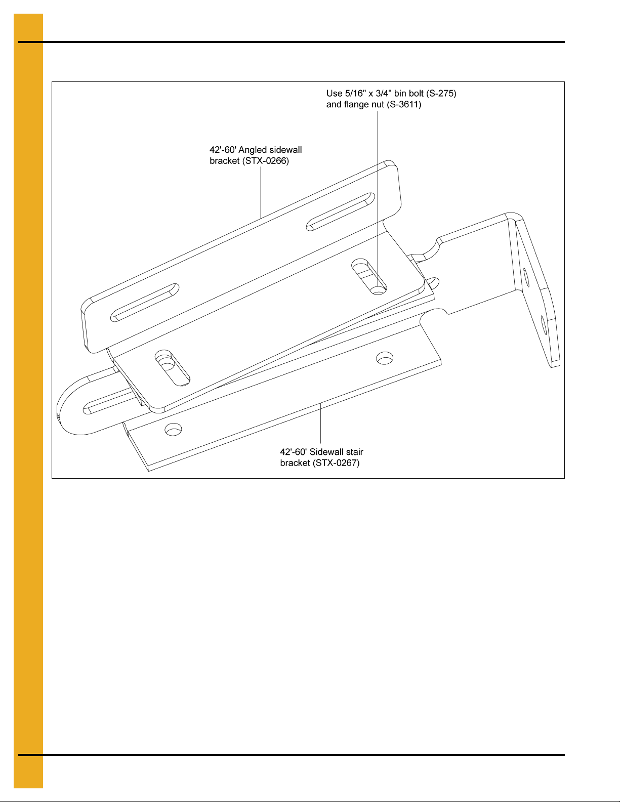
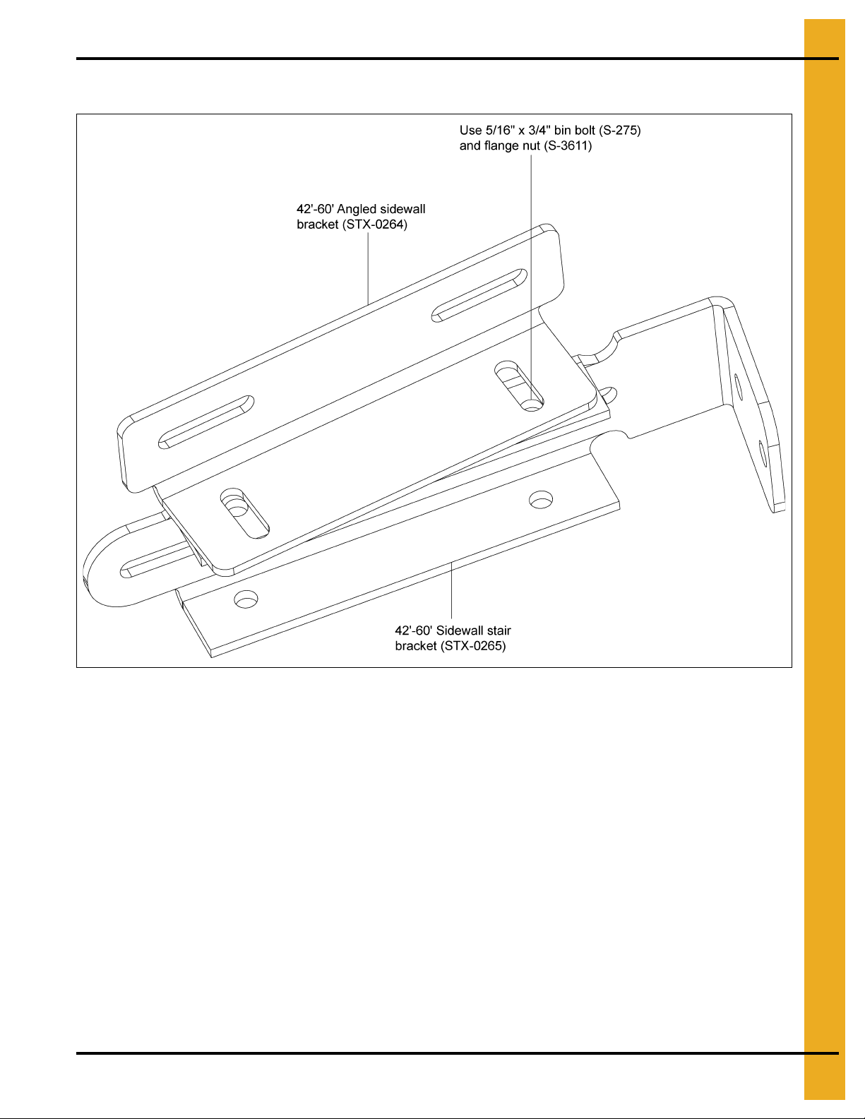
42'-60' Sidewall Stair Bracket Assembly
Figure 5A
36 PNEG-1787 42'-135' “X” Series Sidewall Stair and Eave Platform
Page 37

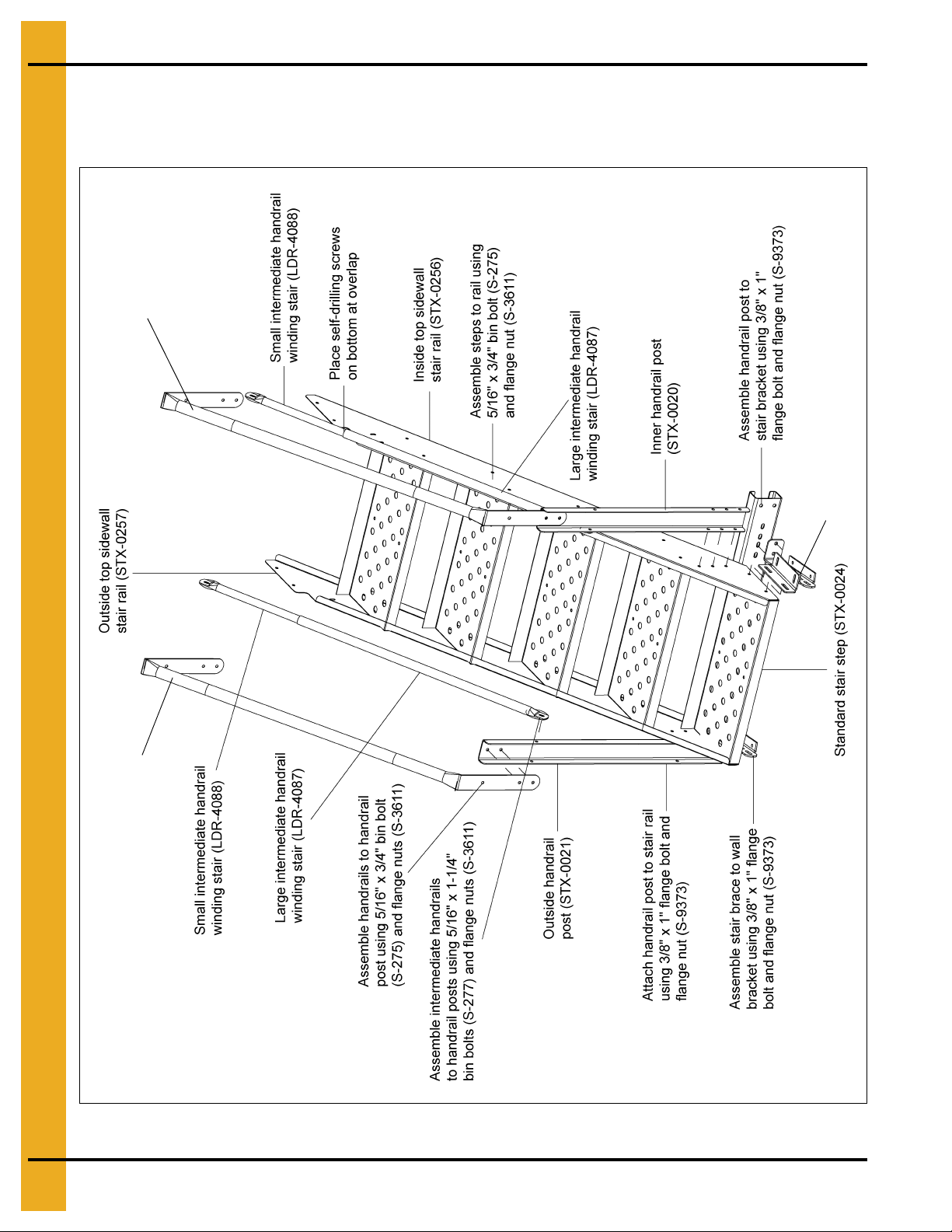
42'-60' Sidewall Stair Sub-assemblies
Top section handrail inside (See chart
on Page 35 for part numbers.)
Top section handrail outside (See chart
on Page 35 for part numbers.)
Stair bracket assembly
(See Page 36 for part numbers.)
“X” Series Top Sidewall Stair Assembly
5. 42'-60' Assembly Instructions
PNEG-1787 42'-135' “X” Series Sidewall Stair and Eave Platform 37
Figure 5B
Page 38

5. 42'-60' Assembly Instructions
Standard section handrail
inside (See chart on Page 35
for part numbers.)
Standard section handrail outside
(See chart on Page 35 for part
numbers.)
Stair bra cke t assembly
(See Page 36 for part numbers.)
42'-60' Sidewall Stair Sub-assemblies (Continued)
“X” Series Standard Stair Assembly
Figure 5C
38 PNEG-1787 42'-135' “X” Series Sidewall Stair and Eave Platform
Page 39
5. 42'-60' Assembly Instructions
Sidewall Stair Bracket Assembly - Reverse
Figure 5D
PNEG-1787 42'-135' “X” Series Sidewall Stair and Eave Platform 39
Page 40
5. 42'-60' Assembly Instructions
Top section handrail inside (See chart
on Page 35 for part numbers.)
Top section handrail outside (See chart
on Page 35 for part numbers.)
Stair bracket assembly
(See Page 39 for part numbers.)
42'-60' Sidewall Stair Sub-assemblies - Reverse
“X” Series Top Stair Assembly - Reverse
Figure 5E
40 PNEG-1787 42'-135' “X” Series Sidewall Stair and Eave Platform
Page 41

5. 42'-60' Assembly Instructions
Standard section handrail outside
(See chart on Page 35 for part
numbers.)
Standard section
handrail inside (See
chart on Page 35 for
part numbers.)
Stair bracket assembly
(See Page 39 for part numbers.)
42'-60' Sidewall Stair Sub-assemblies - Reverse (Continued)
“X” Series Standard Stair Assembly - Reverse
Figure 5F
PNEG-1787 42'-135' “X” Series Sidewall Stair and Eave Platform 41
Page 42
5. 42'-60' Assembly Instructions
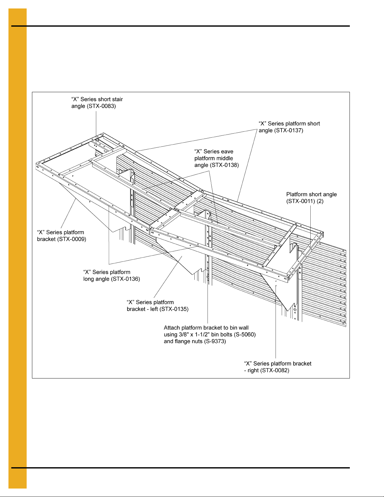
42'-60' Eave Platform Sub-assembly
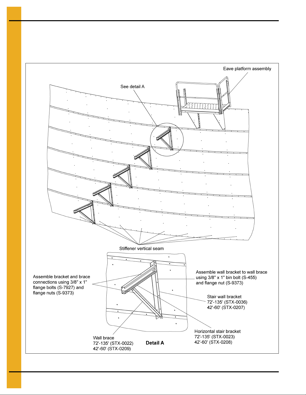
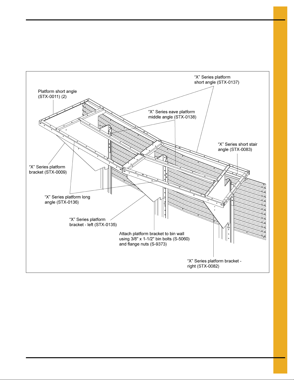
1. Figure 5G shows the assembly of the platform bracket to the stiffeners and sidewall. Platform
bracket must line up with a roof rib and roof beam.
2. Figure 5G also shows the assembly of platform substructure to the platform brackets.
Use 5/16" hardware.
Figure 5G
42 PNEG-1787 42'-135' “X” Series Sidewall Stair and Eave Platform
Page 43
5. 42'-60' Assembly Instructions
42'-60' Eave Platform Sub-assembly (Continued)
3. Figure 5H shows the assembly of the platform posts to the substructure. Use 5/16" hardware.
Figure 5H
PNEG-1787 42'-135' “X” Series Sidewall Stair and Eave Platform 43
Page 44
5. 42'-60' Assembly Instructions
42'-60' Eave Platform Sub-assembly (Continued)
4. Figure 5I shows assembly of handrail to platform posts.
Figure 5I
44 PNEG-1787 42'-135' “X” Series Sidewall Stair and Eave Platform
Page 45

5. 42'-60' Assembly Instructions
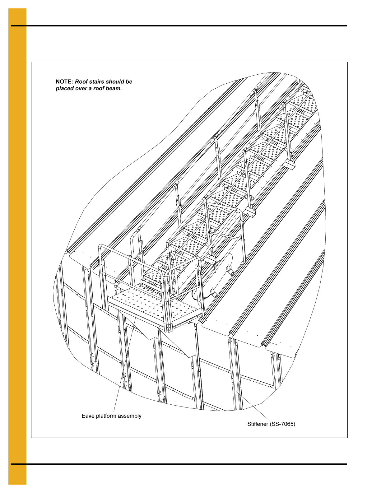
42'-60' Complete Form and Roof Stair Interaction
Figure 5J
Figure 5K shows interaction of sidewall stair, eave platform and roof stairs.
Figure 5K
PNEG-1787 42'-135' “X” Series Sidewall Stair and Eave Platform 45
Page 46
5. 42'-60' Assembly Instructions
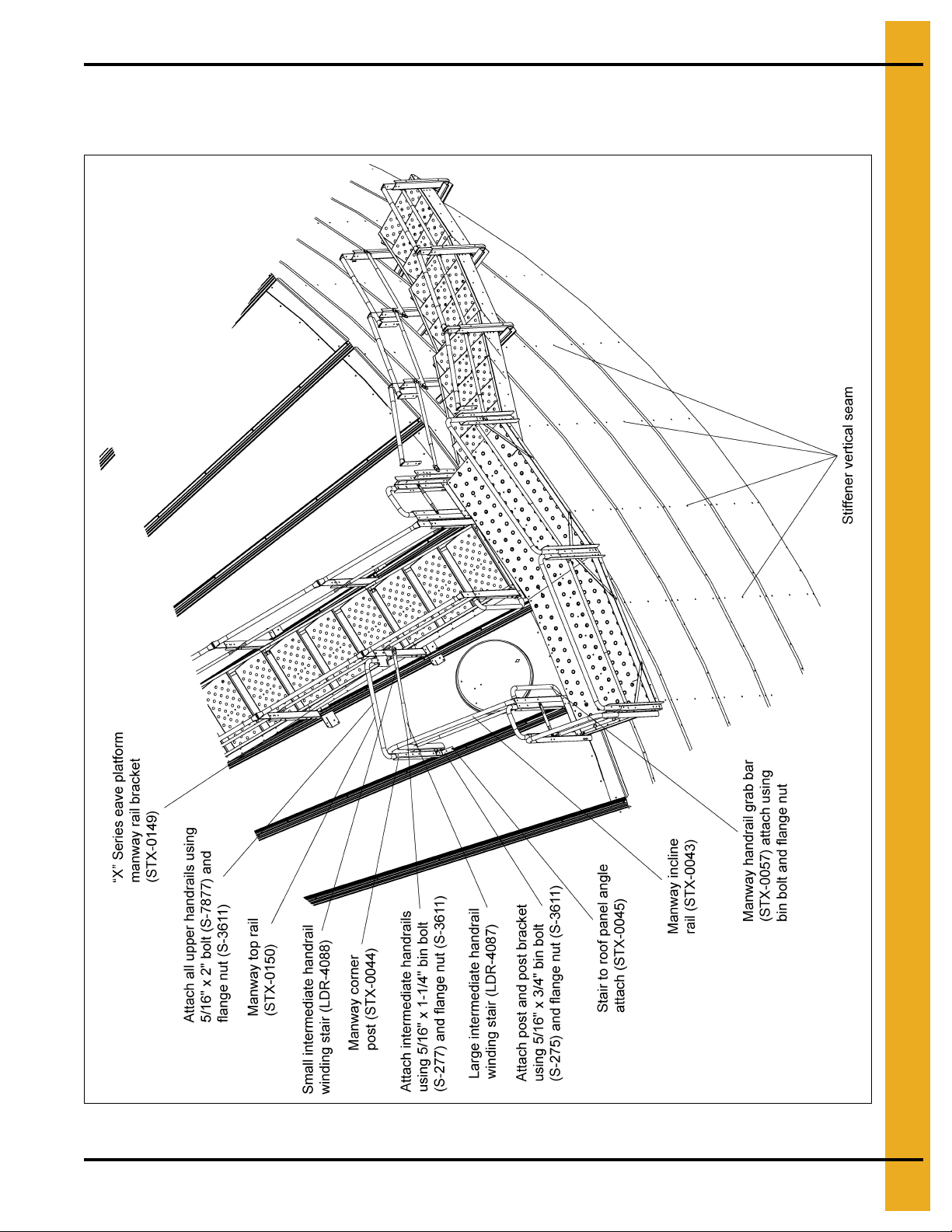
42'-60' Sidewall St air, Eave Platform, Manway Guard and Roof S t air
Interaction Sub-assembly
Figure 5L
46 PNEG-1787 42'-135' “X” Series Sidewall Stair and Eave Platform
Page 47
5. 42'-60' Assembly Instructions
42'-60' Eave Platform Sub-assembly - Reverse
1. Figure 5M shows the assembly of the platform bracket to the stiffeners and sidewall. Platform bracket
must line up with a roof rib and roof beam.
2. Figure 5M also shows the assembly of platform substructure to the platform brackets. Use
5/16" hardware.
Figure 5M
PNEG-1787 42'-135' “X” Series Sidewall Stair and Eave Platform 47
Page 48

5. 42'-60' Assembly Instructions
42'-60' Eave Platform Sub-assembly - Reverse (Continued)
3. Figure 5N shows the assembly of the platform posts to the substructure. Use 5/16" hardware.
Figure 5N
48 PNEG-1787 42'-135' “X” Series Sidewall Stair and Eave Platform
Page 49

5. 42'-60' Assembly Instructions
42'-60' Eave Platform Sub-assembly - Reverse (Continued)
4. Figure 5O shows assembly of handrail to platform posts.
Figure 5O
PNEG-1787 42'-135' “X” Series Sidewall Stair and Eave Platform 49
Page 50

5. 42'-60' Assembly Instructions
42'-60' Eave Platform Sub-assembly - Reverse (Continued)
5. Figure 5P shows interaction of sidewall stair, eave platform and roof stair - reverse.
Figure 5P
50 PNEG-1787 42'-135' “X” Series Sidewall Stair and Eave Platform
Page 51
5. 42'-60' Assembly Instructions
42'-60' Sidewall St air, Eave Plat form, Manway Guard and Roof St air
Interaction Sub-assembly - Reverse
Figure 5Q
PNEG-1787 42'-135' “X” Series Sidewall Stair and Eave Platform 51
Page 52

NOTES
52 PNEG-1787 42'-135' “X” Series Sidewall Stair and Eave Platform
Page 53
6. Warranty
9101239_1_CR_rev7.DOC (revised July 2009)
GSI Group, LLC Limited Warranty
The GSI Group, LLC (“GSI”) warrants products which it manufactures to be free of defects in materials and workmanship
under normal usage and conditions for a period of 12 months after sale to the original end-user or if a foreign sale,
14 months from arrival at port of discharge, whichever is earlier. The end-user’s sole remedy (and GSI’s only obligation)
is to repair or replace, at GSI’s option and expense, products that in GSI’s judgment, contain a material defect in materials
or workmanship. Expenses incurred by or on behalf of the end-user without prior written authorization from the GSI
Warranty Group shall be the sole responsibility of the end-user.
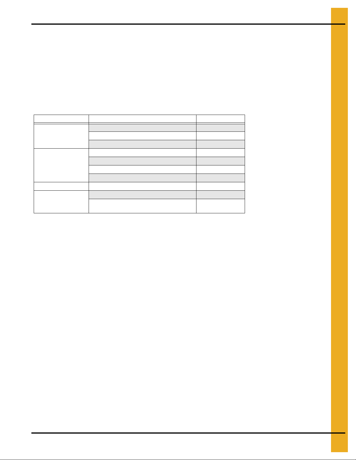
Warranty Extensions:
The Limited Warranty period is extended for the following products:
Product Warranty Period
Performer Series Direct Drive Fan Motor 3 Years
AP Fans and Flooring
Cumberland
Feeding/Watering
Systems
Grain Systems Grain Bin Structural Design 5 Years
Grain Systems
Farm Fans
Zimmerman
All Fiberglass Housings Lifetime
All Fiberglass Propellers Lifetime
Feeder System Pan Assemblies 5 Years **
Feed Tubes (1-3/4" and 2.00") 10 Years *
Centerless Augers 10 Years *
Watering Nipples 10 Years *
Portable and Tower Dryers 2 Years
Portable and Tower Dryer Frames and
Internal Infrastructure †
5 Years
* Warranty prorated from list price:
0 to 3 years - no cost to end-user
3 to 5 years - end-user pays 25%
5 to 7 years - end-user pays 50%
7 to 10 years - end-user pays 75%
** Warranty prorated from list price:
0 to 3 years - no cost to end-user
3 to 5 years - end-user pays 50%
† Motors, burner components
and moving parts not included.
Portable dryer screens included.
Tower dryer screens not included.
GSI further warrants that the portable and tower dryer frame and basket, excluding all auger and auger drive components,
shall be free from defects in materials for a period of time beginning on the twelfth (12
and continuing until the sixtieth (60
th
) month from the date of purchase (extended warranty period). During the extended
th
) month from the date of purchase
warranty period, GSI will replace the frame or basket components that prove to be defective under normal conditions of
use without charge, excluding the labor, transportation, and/or shipping costs incurred in the performance of this
extended warranty.
Conditions and Limitations:
THERE ARE NO WARRANTIES THAT EXTEND BEYOND THE LIMITED WARRANTY DESCRIPTION SET FORTH
ABOVE. SPECIFICALLY, GSI MAKES NO FURTHER WARRANTY OF ANY KIND, EXPRESS OR IMPLIED,
INCLUDING, WITHOUT LIMITATION, WARRANTIES OF MERCHANTABILITY OR FITNESS FOR A PARTICULAR
PURPOSE OR USE IN CONNECTION WITH: (I) PRODUCT MANUFACTURED OR SOLD BY GSI OR (II) ANY ADVICE,
INSTRUCTION, RECOMMENDATION OR SUGGESTION PROVIDED BY AN AGENT, REPRESENTA TIVE OR
EMPLOYEE OF GSI REGARDING OR RELATED TO THE CONFIGURATION, INSTALLATION, LAYOUT, SUITABILITY
FOR A PARTICULAR PURPOSE, OR DESIGN OF SUCH PRODUCTS.
GSI shall not be liable for any direct, indirect, incidental or consequential damages, including, without limitation, loss of
anticipated profits or benefits. The sole and exclusive remedy is set forth in the Limited Warranty, which shall not exceed
the amount paid for the product purchased. This warranty is not transferable and applies only to the original end-user. GSI
shall have no obligation or responsibility for any representations or warranties made by or on behalf of any dealer, agent
or distributor.
GSI assumes no responsibility for claims resulting from construction defects or unauthorized modifications to products
which it manufactured. Modifications to products not specifically delineated in the manual accompanying the equipment at
initial sale will void the Limited Warranty.
This Limited Warranty shall not extend to products or parts which have been damaged by negligent use, misuse, alteration,
accident or which have been improperly/inadequately maintained. This Limited Warranty extends solely to products
manufactured by GSI.
Prior to installation, the end-user has the responsibility to comply with federal, state and local codes which apply to the
location and installation of products manufactured or sold by GSI.
PNEG-1787 42'-135' “X” Series Sidewall Stair and Eave Platform 53
Page 54
This equipment shall be installed in accordance with
the current installation codes and applicable
regulations which should be carefully followed in all
cases. Authorities having jurisdiction should be
consulted before installations are made.
Copyright © 2011 by GSI Group
Printed in the USA
GSI Group
1004 E. Illinois St.
Assumption, IL 62510-0020
Phone: 1-217-226-4421
Fax: 1-217-226-4420
www.gsiag.com
 Loading...