

Page 1
PNEG-1776
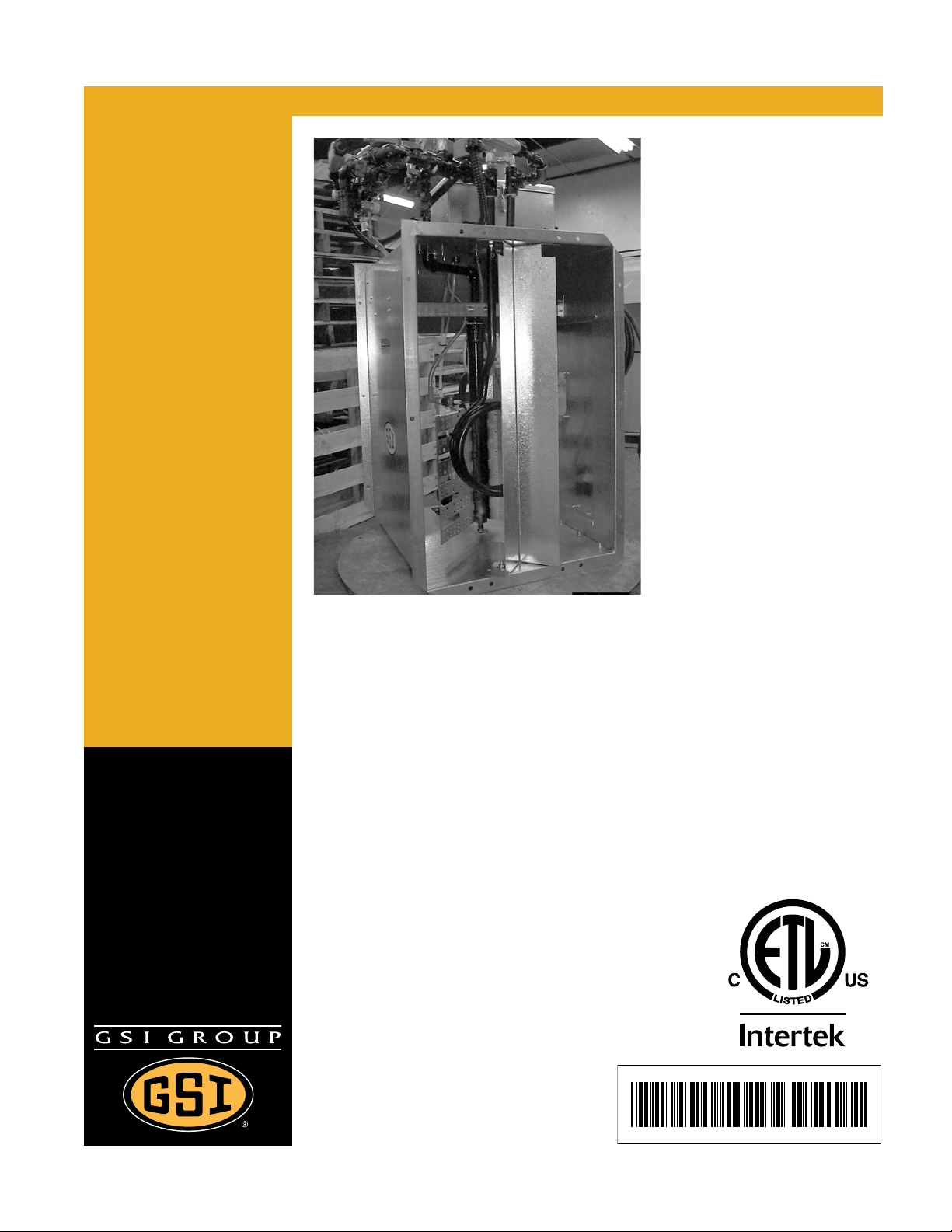
Deluxe Downwind Centrifugal
Heater Inst allation and Operating
Instructions - Canadian
Model # CH_-_ _-_ _-D (HIGH)
Model # CL_-_ _-_ _-D (LOW)
Owner ’s Manual
PNEG-1776
Date: 09-25-12
Page 2

Check List
This equipment shall be installed in accordance with the current inst allation codes for gas burning
appliances and equipment, CAN1-B149.1 and B149.2, or applicable provincial regulations which
should be carefully followed in all cases. Authorities having jurisdiction should be consulted before
installations are made.
1. All wire connections
2. Spark plug gap 0.125
3. Pipe train tightness and gas leaks
4. Flame sensor tight
5. Fuse in place, extra fuse provided
6. Indicator light
7. Pressure gauge
8. Regulator adjusted
9. Shut off valve operates correctly
10. Vapor High-Limit
11. Unit cycles ON to OFF
12. Heat rise even across transition
13. Unit cycles High-Low (High-Low only)
14. All decals and serial number tag
15. Aesthetic appearance
16. Manual
Tester Signature:
Date:______________________________
______________________________
2 PNEG-1776 Deluxe Downwind Heater - Canadian
Page 3

Table of Contents
Contents
Chapter 1 Introduction ..........................................................................................................................................4
Chapter 2 Safety .....................................................................................................................................................5
Safety Guidelines .................................................................................................................................. 5
Fuel Warning ......................................................................................................................................... 6
Power Warning ...................................................................................................................................... 6
Proper Use of Product .................. ................ ................. ................ ................ ................ ........................ 6
Heater Operation ................................................................................................................................... 6
Safety Instructions ..................... ... .... ...................................... .... ... ... ... ... .... ... ... ... .................................. 7
Chapter 3 Decals ....................................................................................................................................................9
Roof Damage Warning and Disclaimer ................................................................................................. 9
Heater Access Door Decals ................................................................................................................ 10
Control Box Decals ............................................................................................................................. 11
Chapter 4 Specifications .....................................................................................................................................12
Heater Specifications .......................................................................................................................... 12
Chapter 5 Installation ..........................................................................................................................................13
Machine to Earth Ground .................................................................................................................... 13
Previously Installed Units ................................. ... ... ... .... ... ... ................................................................ 13
Fuel Connection .................................................................................................................................. 13
Liquid Propane Models .................................................... ... ... .... ... ... ... ... .... ... ... ... .... ............................ 13
Propane Vapor Models ....................................................................................................................... 14
Natural Gas Models ............................................................................................................................ 14
Standard Heater - Second Heater Installation ........................................................ ... ... ... ... .... ... ... ... ... 15
Electrical Installation (460V Fans) .......................... .................... ................... ................... ................... 16
Bin Configuration ................................................................................................................................. 17
Plenum Thermostat Mounting ............................................................................................................. 17
Transition High-Limit Installation ......................................................................................................... 19
Chapter 6 Operation ............................................................................................................................................20
Operating Temperature Table .......................... ... ... .......................................... ................................... 20
Cycling Heater Operation .................................................................................................................... 20
High-Low Heater Operation ................................................... .......................................... ................... 21
Adjusting the Vaporizer ....................................................................................................................... 22
BTUs for Gauge Pressure (PSI) Reading Propane Models (Approximate) ........................................ 23
BTUs for Gauge Pressure (PSI) Reading Natural Gas Models (Approximate) ................................... 24
Chapter 7 Service .................................................................................................................................................25
Seasonal Inspection and Service ........................................................................................................ 25
Chapter 8 Troubleshooting - Heater ...................................................................................................................27
Chapter 9 Wiring Diagrams .................................................................................................................................28
CSA Centrifugal Heater Schematic ........................ ... .... ... ... ... .... ... ... ... ... .... ... ... ................................... 28
CSA Centrifugal Diagram .................................................................................................................... 29
Chapter 10 Parts List ...........................................................................................................................................31
CSA Heater Control Box Assembly (HF-8184) .................................................................................. 32
Downwind Centrifugal Heater Control Parts ...................................................................................... 34
Downwind Centrifugal LP Pipe Train Components ........................................................................... 36
Downwind Centrifugal LP High-Low Pipe Train Components ........................................................... 38
Downwind Centrifugal NG Pipe Train Components .......................................................................... 40
Downwind Centrifugal NG High-Low Pipe Train Components .......................................................... 41
Downwind Centrifugal Propane Vapor Pipe Train Components ........................ .......................... ...... 42
Downwind Centrifugal Propane Vapor High-Low Pipe Train Components ....................................... 44
15 HP and 30 HP Centrifugal Housing .............................................................................................. 46
LP Supply Pipe Train Assembly ........ ... ... .......................................... ... .... ... ...................................... 47
Chapter 11 Warranty ............................................................................................................................................49
PNEG-1776 Deluxe Downwind Heater - Canadian 3
Page 4

1. Introduction
Thank you for choosing a GSI product. It is designed to give excellent performance and service for
many years.
This manual describes the operation of the CSA Deluxe Downwind Heater. It is designed for low to
medium temperature grain conditioning and is ideal for the aeration of rice, popcorn or other select grains.
It is available in both propane vapor and natural gas models.
Our foremost concern is your safety and the safety of others associated with this equipment. We want to
keep you as a customer. This manual is to help you understand safe operating procedures and some
problems which may be encountered by the operator and other personnel.
As owner and/or operator, it is your responsibility to know what requirements, hazards and precautions
exist and to inform all personnel associated with the equipment or in the area. Safety precautions may be
required from the personnel. Avoid any alterations to the equipment. Such alterations may p roduce a very
dangerous situation where SERIOUS INJURY or DEATH may occur.
This equipment shall be installed in accordance with the current installation codes and applicable
regulations which should be carefully followed in all cases. Authorities having jurisdiction should be
consulted before installations are made.
4 PNEG-1776 Deluxe Downwind Heater - Canadian
Page 5
2. Safety
DANGER
WARNING
CAUTION
NOTICE
This is the safety alert symbol. It is used to alert you
to potential personal injury hazards. Obey all safety
messages that follow this symbol to avoid possible
injury or death.
WARNING indicates a hazardous situation which, if not
avoided, could result in death or serious injury.
CAUTION, used with the safety alert symbol, indicates a
hazardous situation which, if not avoided, could result in
minor or moderate injury.
NOTICE is used to address practices not related to
personal injury.
DANGER indicates a hazardous situation which, if not
avoided, will result in death or serious injury.
Personnel operating or working around electric fans should read this manual. This
manual must be delivered with the equipment to its owner. Failure to read this manual
and its safety instructions is a misuse of the equipment.
WARNING! BE ALERT!
Safety Guidelines
This manual contains information that is important for you, the owner/operator, to know and understand.
This information relates to protecting personal safety and preventing equipment problems. It is the
responsibility of the owner/operator to inform anyone operating or working in the area of this equipment
of these safety guidelines. To help you recognize this information, we use the symbols that are defined
below. Please read the manual and pay attention to these sections. Failure to read this manual and its
safety instructions is a misuse of the equipment and may lead to serious injury or death.
PNEG-1776 Deluxe Downwind Heater - Canadian 5
Page 6
2. Safety
CAUTION
Do not use propane tanks which have previously been used for ammonia unless
they have been purged according to procedures of the National LP Association.
Be sure fuel supply system complies with all local codes for LP gas installations.
DO NOT USE FLAME FOR LEAK TESTING.
Fuel Warning
WARNING
Power Warning
Be sure power is disconnected and locked out before installation. Failure to do so may cause serious injury
or death.
IMPORTANT: Heater must be interlocked with fan for safe operation.
IMPORTANT: Thermostat must be installed for safe operation.
Proper Use of Product
This product is intended for the use of grain drying only. Any other use is a misuse of this product. This
product has sharp edges. These sharp edges may cause serious injury. To avoid injury handle sharp
edges with caution and use proper protective clothing and equipment at all times. Guards are removed for
illustration only. All guards must be in place before and during operation.
Heater Operation
Thank you for choosing a GSI product. It is designed to give excellent performance and service for
many years.
This manual describes the operation of the GSI CSA Deluxe Downwind Centrifugal Heater. Many models
are available to accommodate low, medium or high temperature grain conditioning.
6 PNEG-1776 Deluxe Downwind Heater - Canadian
Page 7
2. Safety
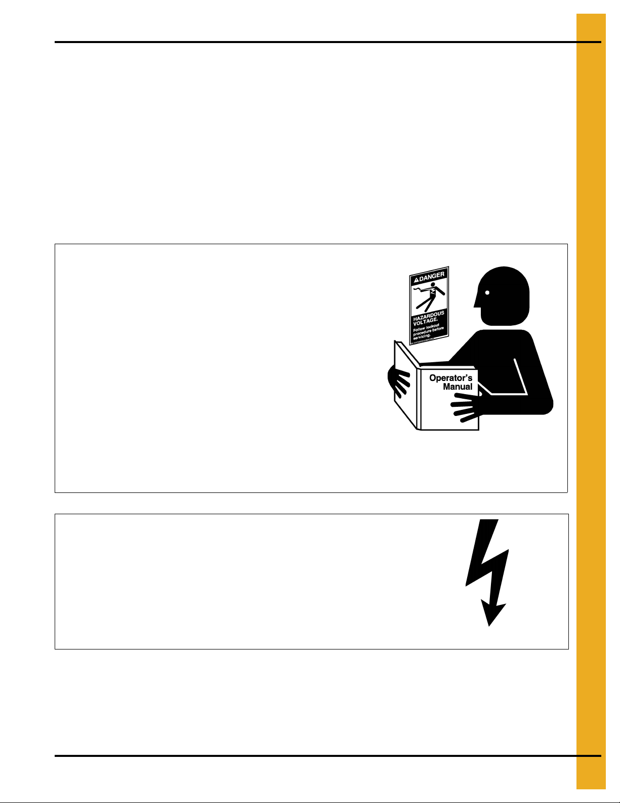
Follow Safety Instructions
Carefully read all safety messages in this manual and
safety signs on your machine. Keep signs in good
condition. Replace missing or damaged safety signs. Be
sure new equipment components and repair parts include
the current safety signs. Replacement safety signs are
available from the manufacturer.
Learn how to operate the machine and how to use controls
properly. Do not let anyone operate without instruction.
Keep your machinery in proper working condition.
Unauthorized modifications to the machine may impair
the function and/or safety and affect machine life.
If you do not understand any part of this manual or need
assistance, contact your dealer.
Read and Understand Manual
Install and Operate Electrical Equipment Properly
Electrical controls should be installed by a qualified electrician
and must meet the standards set by the National Electrical Code
and all local and state codes.
Disconnect and lock out all power sources before installing
wires/cables or servicing equipment.
Electric Shock Hazard
Safety Instructions
Our foremost concern is your safety and the safety of others associated with this equipment. We want to
keep you as a customer. This manual is to help you understand safe operating procedures and some
problems that may be encountered by the operator and other personnel.
As owner and/or operator, it is your responsibility to know what requirements, hazards, and precautions
exist, and to inform all personnel associated with the equipment or in the area. Safety precautions may be
required from the personnel. Avoid any alterations to the equipment. Such alterations may produce a very
dangerous situation where SERIOUS INJURY or DEATH may occur.
This equipment shall be installed in accordance with the current installation codes and applicable
regulations, which should be carefully followed in all cases. Authorities having jurisdiction should be
consulted before installations are made.
PNEG-1776 Deluxe Downwind Heater - Canadian 7
Page 8
2. Safety
Install and Operate Gas-Fired Equipment Properly
Fuel supply should be installed by a qualified gas
technician and must meet local and state codes for
gaseous fuel supplies.
Disconnect and lock out all fuel sources before
servicing equipment.
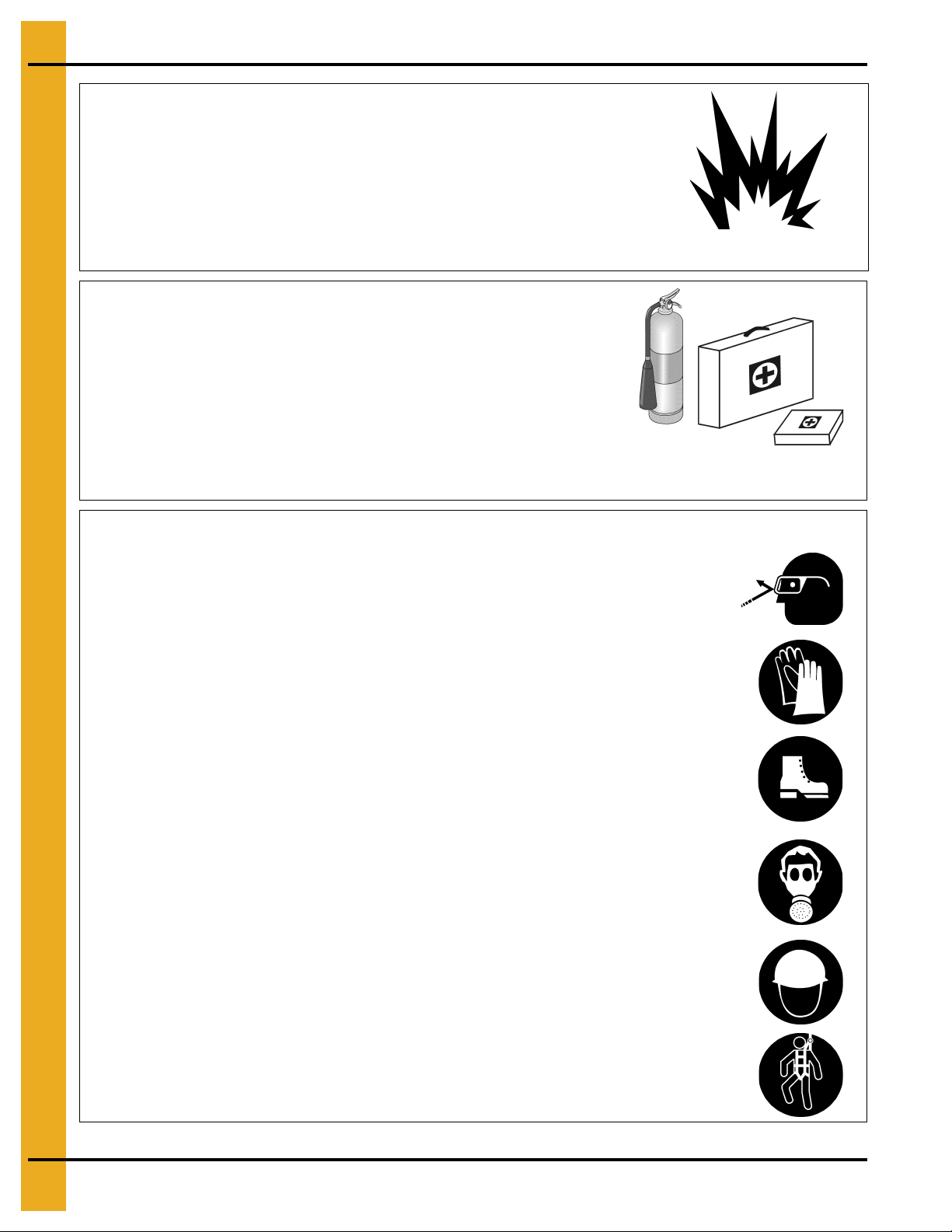
Explosive Gases
Prepare for Emergencies
Be prepared if fire starts.
Keep a first aid kit and fire extinguisher handy.
Keep emergency numbers for doctors, ambulance service,
hospital, and fire department near your telephone.
Keep Emergency Equipment
Quickly Accessible
Wear Protective Clothing
Wear close-fitting clothing and safety equipment appropriate
to the job.
Remove all jewelry.
Tie long hair up and back.
Wear safety glasses at all times to protect eyes from debris.
Wear gloves to protect your hands from sharp edges on
plastic or steel parts.
Wear steel-toed boots to help protect your feet from falling
debris. Tuck in any loose or dangling shoestrings.
A respirator may be needed to prevent breathing potentially
toxic fumes and dust.
Wear a hard hat to help protect your head.
Wear appropriate fall protection equipment when working at
elevations greater than six feet (6').
Eye Protection
Gloves
Steel-Toed Boots
Respirator
Hard Hat
Fall Protection
8 PNEG-1776 Deluxe Downwind Heater - Canadian
Page 9
3. Decals
The GSI Group recommends contacting your local power company, and having a representative survey
the installation so the wiring is compatible with their system, and adequate power is supplied to the unit.
If a decal is damaged or missing, contact:
GSI Decals
1004 E. Illinois St.
Assumption, IL. 62510
Phone: 1-217-226-4421
A free replacement will be sent to you.
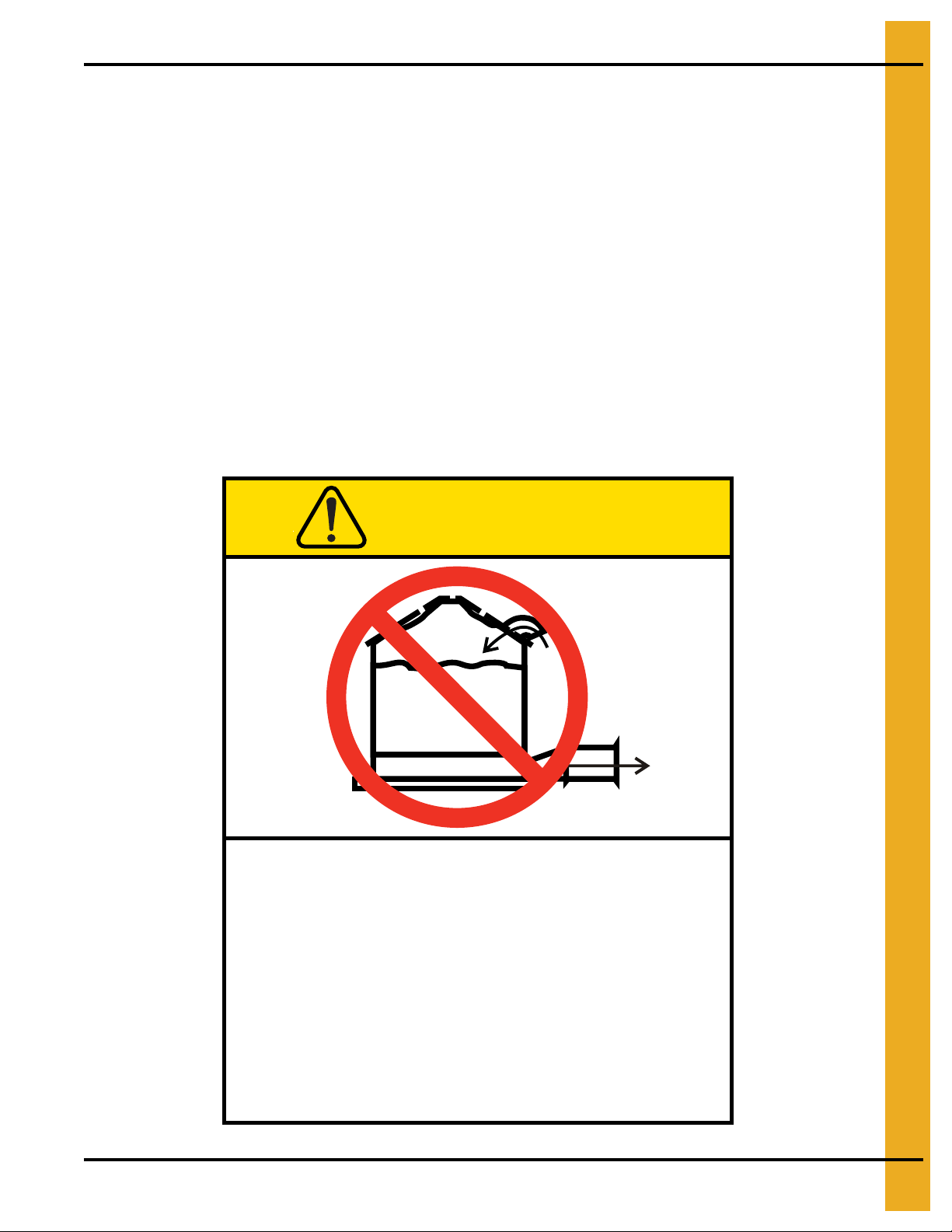
Roof Damage Warning and Disclaimer
The manufacturer does not warrant any roof damage caused by excessive vacuum or internal
pressure from fans or other air moving systems. Adequate ventilation and/or “makeup air” devices
should be provided for all powered air handling systems. The manufacturer does n ot recommend
the use of downward flow systems (suction). Severe roof damage can result fro m any blockage of
air passages. Running fans during high humidity/cold weather conditions can cause air exhaust
or intake ports to freeze.
CAUTION
Excessive vacuum (or pressure) may
damage roof. Use positive aeration
system. Make sure all roof vents are
open and unobstructed. Start roof
fans when supply fans are started.
Do not operate when conditions exist
that may cause roof vent icing.
GSI Group, Inc. 217-226-4421
PNEG-1776 Deluxe Downwind Heater - Canadian 9
DC-969
Page 10
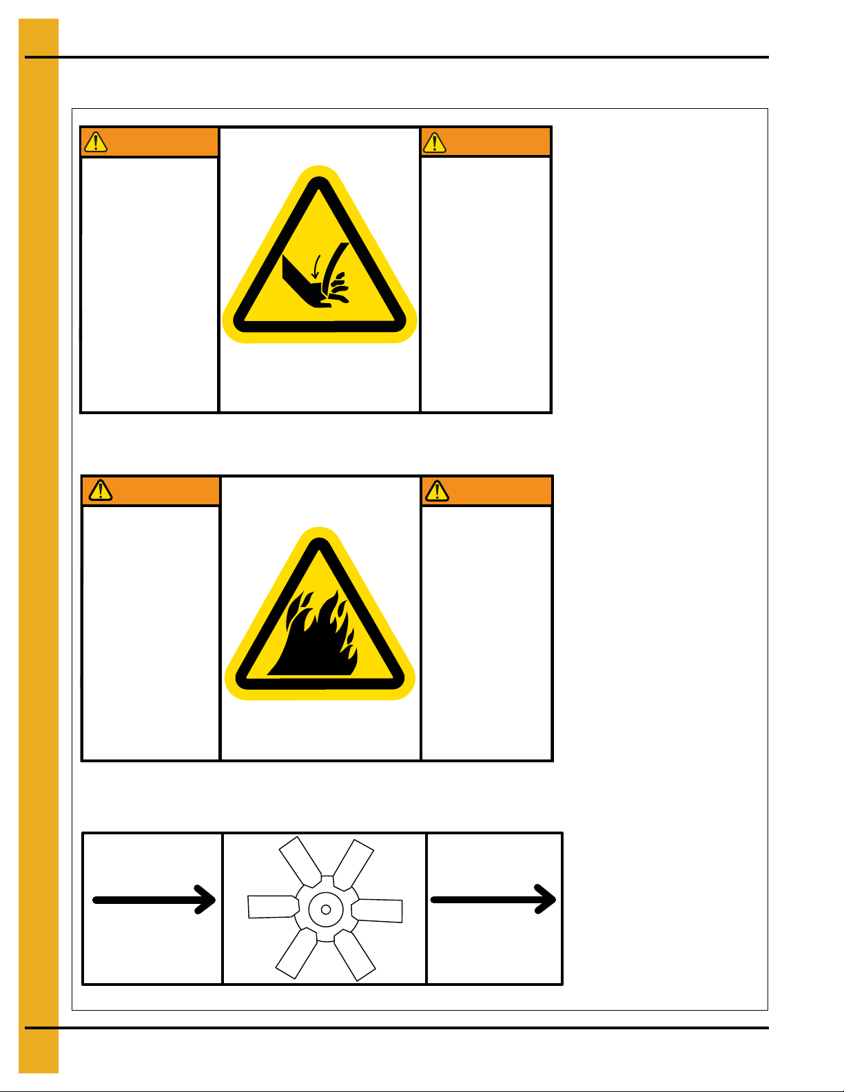
3. Decals
DC-1959
Flame and pressure
beyond door can
cause serious injury.
Do not operate with
service door removed.
Keep head and
hands clear.
La flamme et la
pression au-delà de la
porte peuvent causer
des dommages
sérieux. Ne pas faire
fonctionner si la porte
de service est
enlevée. Gardez les
mains et la tête
éloignés.
WARNING
GSI Group 217-226-4421
AVTERISSEMENT
AIRFLOW
AIRFLOW
CIRCULATION D’AIR
CIRCULATION D’AIR
DC-1971
Size: 4-7/8" x 3"
Located above access
door on heater housing.
DC-1949
DC-1959
Size: 4-7/8" x 3"
Located above access door
on heater housing.
DC-1971
Size: 4-3/4" x 1-5/8"
Located above access
door on heater housing.
Heater Access Door Decals
WARNING
Stay clear of rotating
blade. Blade could
start automatically.
Can cause serious
injury. Disconnect
power before
servicing.
AVERTISSEMENT
Restez éloigné de la
lame tournante. La
lame peut se mettre
en marche
automatiquement.
Peut causer de
sérieuses blessures.
Vérouillez le courant
avant l’entretien.
DC-1949GSI Group Inc. 217-226-4421
10 PNEG-1776 Deluxe Downwind Heater - Canadian
Page 11
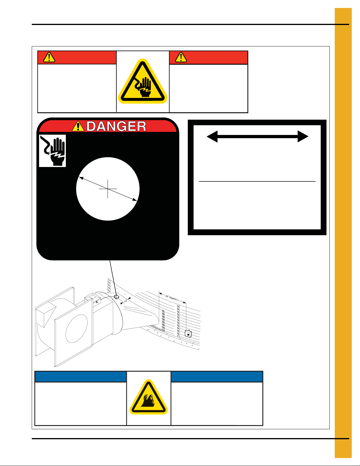
Control Box Decals
DANGER
DANGER
WARMER
PLUS CHAUD
PLUS FROID
COLDER
VAPORIZER ADJUSTMENT
AJUSTEMENT DU VAPORISATEUR
Vaporizer coil should be adjusted so that vapor
pipe train is warm (100-125 degrees F) to
the touch.
La bobine du vaporisateur devrait être ajustée
pour que la vapeur du conduit de transmission
soit chaude au toucher (100-125 degrés F˚).
DC-535
NOTICE
NOTICE
Size: 4-3/8" x 1-3/8"
Located in control box on
side opposite switches.
DC-1948
HIGH VOLTAGE.
Will cause injury or death.
Lockout power before servicing.
HAUTE TENSION.
Causera des blessures ou la mort.
Fermez le courant avant l’entretien.
Remove plug to
reset high limit.
Enlevez le contact pour
reinitialiser la limite élévée.
DC-1165
DC-535
DC-1165
DC-1702
Size: 5.825" x 1-1/2"
3. Decals
DANGER
HIGH VOLTAGE
Will cause serious
injury or death.
Lockout power
before servicing.
DANGER
HAUTE TENSION
Causera de sérieuses
blessures ou la mort.
Couper/verrouiller le
courant avant l’entretien.
DC-1948GSI Group 217-226-4421
DC-1948
Thermostat must be installed for
operation.
Failure to do so may damage
equipment and cause fire.
PNEG-1776 Deluxe Downwind Heater - Canadian 11
NOTICE
NOTICE
Le thermostat doit être installé
pour fonctionner.
Omettre cette installation peut
endommager l’équipement et
provoquer un feu.
DC-1702
Page 12
4. Specifications
Heater Specifications
All Models
15 HP 30 HP
Inside Height 30-1/4" 33-1/4"
Inside Width 19-1/2" 21-3/4"
Length 33" 33"
High Temp BTU Rating 2,300,000 4,000,000
Maximum Fuel Flow (GPH) 26 44
Orifice 17/64 21/64
Liquid Propane
Natural Gas
Operating Pressure Range 1-15 1-15
Minimum Line Size 1/2" 1/2"
Maximum Fuel Flow (CFH) 2212 3173
Orifice 21/64 7/16
Operating Pressure Range 1-7 1-7
Minimum Line Size 1" 1"
12 PNEG-1776 Deluxe Downwind Heater - Canadian
Page 13
5. Installation
Always disconnect and lock out power before working on or around heater.
Machine to Earth Ground
It is very important that a machine to earth ground rod be installed at the fan. This is true even if there is
a ground at the pole 15' away. This ground needs to be as close to the fan as possible, but no more than
8' away. The ground rod should be connected to the fan contro l panel with at least a # 6 solid bare copper
ground wire, or in accordance with local requirements. The machine to earth ground provides additional
safety if there is a short. It also provides the grounding necessary for long life and operation of the solid
state circuit boards used on control circuits and the electronic ignition systems.
Previously Installed Units
It is recommended that previously installed units be checked to see that a machine to earth ground
has been installed by an electrician.
Standard electrical safety practices and codes should be used when working with a heater. Refer to the
National Electric Code Standard Handbook by the National Fire Protection Association. A qualified
electrician should make all wiring installations.
WARNING
Fuel Connection
IMPORTANT: Do not use propane tanks that have previously been used for ammonia unless they have
been purged according to procedures of the National LP association.
Fuel supply system must comply with local codes for LP gas installation.
Liquid Propane Models
1. LP models are designed to run on liquid propane with liquid draw from the propane tank. Avoid using
propane supply tanks that have been used for vapor draw for long periods of time. When using liquid
draw systems any moisture that may be present in tank or lines may freeze when system is used in
cold weather. To avoid this situation, purge the system with methanol.
2. Run proper size line (See Specifications on Page 12) to liquid pipe train on heater. Have a qualified
gas service person inspect installation to be sure that everything is installed according to local codes
and ordinances.
3. After installation is complete check all connections for leaks with liquid detergent or comparable.
Wear rubber gloves and eye protection. Avoid contact with liquid propane. DO NOT USE FLAME
FOR LEAK TESTING.
PNEG-1776 Deluxe Downwind Heater - Canadian 13
Page 14

5. Installation
Propane Vapor Models
1. Propane vapor models are designed to run directly off of a supply tank or from a separate
external vaporizer.
2. Run proper size line (See Specifications on Page 12) to pipe train on heater. Have a qualified gas
service person inspect installation to be sure that everything is installed according to local codes
and ordinances.
3. After installation is complete check all connections for leaks. DO NOT USE FLAME FOR
LEAK TESTING.
Natural Gas Models
1. Natural gas models are designed to run directly off of a supply tank or from a separate
external vaporizer.
2. Run proper size line (See Specifications on Page 12) to pipe train on heater. Have a qualified gas
service person inspect installation to be sure everything is installed according to local codes
and ordinances.
3. After installation is complete check all connections for leaks. DO NOT USE FLAME FOR
LEAK TESTING.
14 PNEG-1776 Deluxe Downwind Heater - Canadian
Page 15
5. Installation
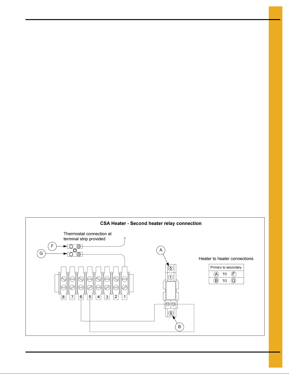
Standard Heater - Second Heater Installation
Two (2) standard heaters may be connected to one grain drying system and wired so they cycle tog ether.
One of the heaters should have a thermostat connected to it as per the installation instructions. That
heater will be referred to as the primary. The other heater (without the thermostat) will be referred to as
the secondary.
1. Install relay base (TD-100283) in primary heater control box.
2. Connect wire between terminal 13 on relay base to terminal 5 on terminal strip in primary heater.
3. Connect wire between terminal 14 on relay base to terminal 6 on terminal strip in primary heater.
4. Run two (2) wires (18 gauge) between primary and secondary heater.
5. Connect wires to terminals 5 and 9 (points A and B) on relay base in primary heater.
6. Connect wire from terminal 9 in primary to (point F) in secondary unit.
7. Connect wire from terminal 5 in primary to (point G) in secondary unit.
8. Install relay (TD-100282) in relay base.
Follow these additional steps for HIGH-LOW units.
1. Install relay base (TD-100283) in master heater control box.
2. Connect wire between terminal 13 on relay base to green wire from HIGH-LOW thermostat in master
unit. Do not disconnect other wires from green wire 3. Connect wire between terminal 14 on relay
base to terminal 14 on other relay base in master heater.
3. Run two (2) wires (18 gauge) between master and slave heater.
4. Connect wires to terminals 5 and 9 (points A and B) on relay base in master heater.
5. Connect wire from terminal 9 in master to terminal 6 (point G) in slave unit.
6. Connect wire from terminal 5 in master to cycle solenoid and red light in slave unit. Do not connect
wire to side of cycle solenoid and light that are connected to terminal.
Figure 5A CSA Heater - Second Heater Relay Connection
PNEG-1776 Deluxe Downwind Heater - Canadian 15
Page 16

5. Installation
Electrical Installation (460V Fans)
1. Connect power cord to fan control box.
2. Make field connections of wires in fan box as shown in Figure 5B. 110V power supply or
0.5 KVA 460V to 110V transformer must be used to supply power for heater.
3. Connect deluxe thermostat control (optional) in heater box as shown in Figure 5A on Page 15.
IMPORTANT: Heater must be interlocked with fan for safe operation.
IMPORTANT: Thermostat must be installed for safe operation.
Figure 5B 460 Volt Fan Control Box
16 PNEG-1776 Deluxe Downwind Heater - Canadian
Page 17

Bin Configuration
Thermostat must be installed to operate as plenum high-limit safety.
5. Installation
Figure 5C
IMPORTANT: When mounting two (2) heaters on a bin it is imperative that they be situated as shown in
Figure 5C. Plenum thermostat must be to the right of master heater and master heater must
be to the right of slave heater.
Plenum Thermostat Mounting
The plenum thermostat must be ordered separately from the heater unit.
1. Follow installation instructions provided with the thermostat assembly.
2. Position the housing so that the bolt flanges are vertical and the cord exits the housing from the
bottom. Mark position.
3. Use 6 (4.00") or 8 (2.66") self-drilling screws to mount the housing to the bin sidewall. DO NOT
TIGHTEN COMPLETELY. Insert corrugation seal into gap between housing and sidewall.
Tighten screws.
4. Caulk between the housing and the sidewall to seal.
CAUTION
Heater control device (thermostat or humidistat) is required for heater warranty on all heaters.
PNEG-1776 Deluxe Downwind Heater - Canadian 17
Page 18

5. Installation
Figure 5D Plenum Thermostat Mounting on Bin Wall
Figure 5E Side view of thermostat showing corrugation seal.
18 PNEG-1776 Deluxe Downwind Heater - Canadian
Page 19

Transition High-Limit Installation
1. Mark location on transition one foot up from the bottom (entrance collar) and centered in
the transition.
2. Drill or knock out 7/8" diameter hole on marked location.
3. Install transition high-limit using supplied self-drilling screws.
5. Installation
Figure 5F The transition connecting the heater to the bin with the plenum thermost at in place.
PNEG-1776 Deluxe Downwind Heater - Canadian 19
Page 20

6. Operation
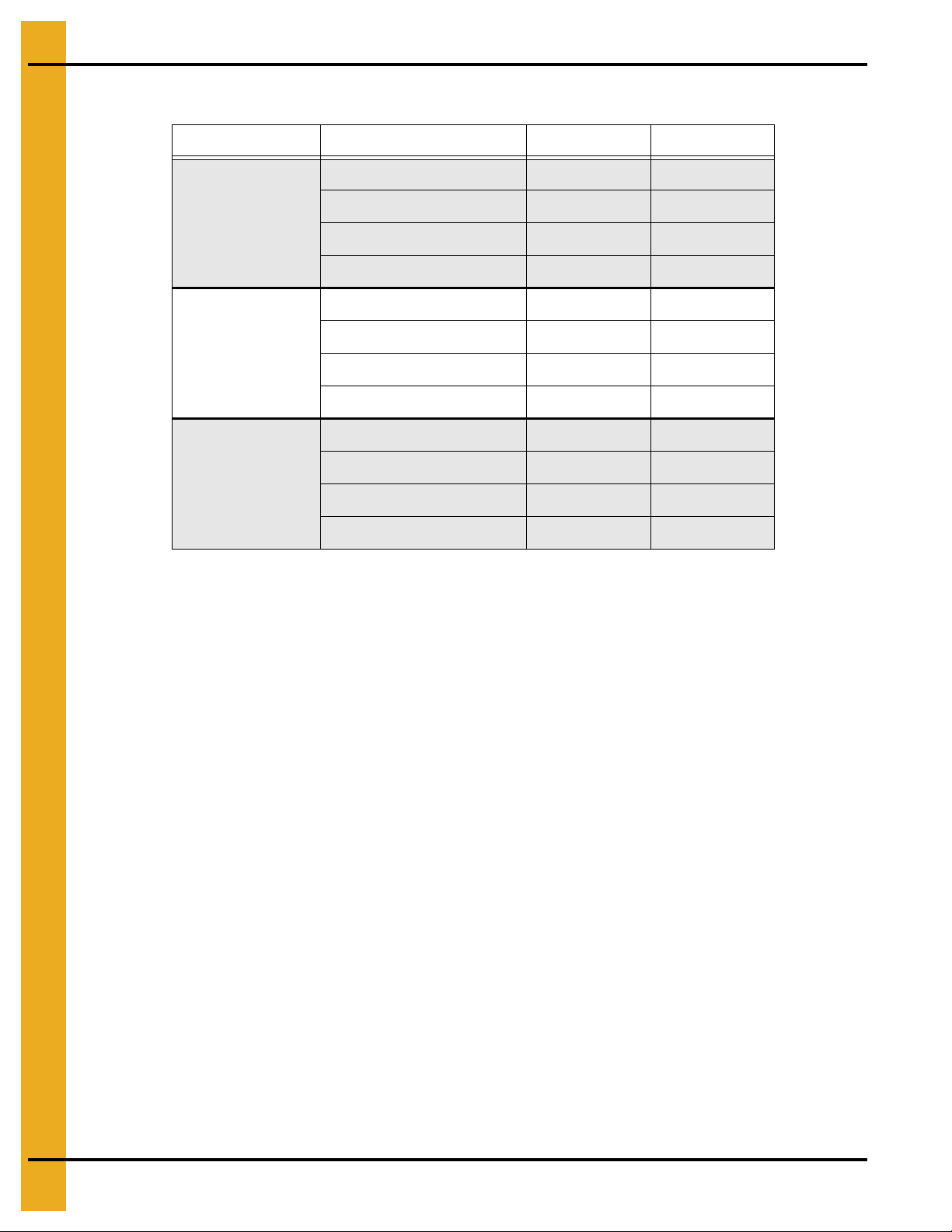
Operating Temperature Table
IMPORTANT: Do not exceed plenum temperatures listed in table.
Low Temperature Batch
Corn 5°-20° Above Ambient Temperature 120° 140° 160°
Rice 5°-10° Above Ambient Temperature 100° 100° Not Recommended
Beans and
Wheat
5°-20° Above Ambient Temperature 110° 120° Not Recommended
High Temperature
Batch Dry No Stirring
High Temperature
with Stirring
Continuous Flow
(Recirculating)
This table is not intended as a drying guide. It should be used as a reference for setting m aximum
plenum temperature for safe operation.
Cycling Heater Operation
1. Thermostat must be wired into heater control box for heater to operate.
2. Open all manual shut off valves to heater unit.
3. Start fan. This will supply power to heater.
4. Turn thermostat dial to its highest setting.
5. Turn toggle switch ON.
6. Heater should now be lit. If not check to see that all gas is ON.
7. Set thermostat to desired setting. (See deluxe thermostat manual for adjusting deluxe
thermostat control.)
8. Gas pressure should be adjusted so burner is on 75% of the time.
9. Watch as burner goes through a few cycles, to be sure that it is operating properly.
20 PNEG-1776 Deluxe Downwind Heater - Canadian
Page 21

6. Operation
High-Low Heater Operation
1. High-limit and cycling thermostat must be wired into heater control box for heater to operate.
2. Open all manual shut off valves to heater unit.
3. Start fan. This will supply power to heater.
4. Turn thermostat dial to its highest setting.
5. Turn toggle switch ON. Both indicator lights should illuminate indicating power to the control circuit.
6. Heater should now be lit. If not check to see that all gas is ON.
7. Loosen the retaining nut holding bypass valve screw in place. Open the bypass valve all the way.
8. Turn thermostat dial back slowly until heater cycles to low flame.
9. Adjust bypass valve so that low flame pressure is at desired setting. (As low as possible.)
10. Turn thermostat dial to desired setting and wait for bin plenum to come up to temperature. Heater
should cycle to low flame after a few minutes.
11. If heater does not cycle to low flame increase high flame gas pressure by adjusting the regulator.
High flame should be adjusted so the heater cycles at least once a minute. Low flame should be
12.
adjusted so there is enough flame for unit to keep operating.
13. Watch as burner goes through a few cycles, to be sure that it is operating properly back to high flame.
Figure 6A
PNEG-1776 Deluxe Downwind Heater - Canadian 21
Page 22

6. Operation
Adjusting the Vaporizer
1. Vaporizer should be adjusted so the vapor pipe train runs warm to the touch (100°-120°F).
2. Loosen 5/16" pivot bolts on adjustment bracket.
3. Tilt vaporizer away from burner to cool. Tilt toward burner to heat. Vaporizer may be raised or lowered
for vertical adjustments.
4. Tighten 5/16" pivot bolts to fix vaporizer position.
IMPORTANT: Only move vaporizer 1" at a time. Allow heater to run a few minutes for temperature
to equalize.
Figure 6B Figure 6C
Vaporizer adjustment: Away from burner to cool. Toward burner to heat.
22 PNEG-1776 Deluxe Downwind Heater - Canadian
Page 23

6. Operation
BTUs for Gauge Pressure (PSI) Reading Propane Models
(Approximate)
High Temperature
Operating Pressure (PSI)
Diameter
2 4 6 8 10 12 14 16 18 20
15 HP 1,315,765 1,797,071 2,206,654 2,557,392 2,861,118 3,128,624 3,369,657 3,592,923 3,806,082 4,015,753
30 HP 2,007,794 2,742,244 3,367,248 3,902,456 4,365,927 4,774,128 5,141,934 5,482,626 5,807,897 6,127,845
Gauge Pressure (PSI) Reading to Maintain Temp (Approximate)
Heat Rise (F)
Diameter Static Pressure
60 80 100 120 140 160 180
2" 2 3 4 6 8 10 13
15 HP
30 HP
4" 1 2 3 5 6 8 10
6" 1 1 2 3 5 6 7
2" 2 3 5 6 9 11 14
4" 1 3 4 6 7 912
6" 1 2 3 5 6 810
8" 1 2 3 4 578
PNEG-1776 Deluxe Downwind Heater - Canadian 23
Page 24

6. Operation
BTUs for Gauge Pressure (PSI) Reading Natural Gas Models
(Approximate)
High Temperature
Operating Pressure (PSI)
Diameter12345678910
15 HP 1006116 1268133 1509530 1732015 1937235 2126771 2302144 2464811 2616167 2757542
30 HP 1788650 2254458 2683609 3079138 3443973 3780926 4092700 4381886 4650963 4902297
Gauge Pressure (PSI) Reading to Maintain Temp (Approximate)
Heat Rise (F)
Diameter Static Pressure
60 80 100 120 140 160 180
2" 2 3 5 7 9 11 14
15 HP
30 HP
4" 1 2 4 5 7 9 11
6" 1 2 3 4 5 6 8
2" 1 2 4 5 7 9 11
4" 1 2 3 5 6 8 10
6" 1 2 3 4 5 6 8
8" 1 1 2 3 4 6 7
24 PNEG-1776 Deluxe Downwind Heater - Canadian
Page 25

7. Service
Seasonal Inspection and Service
All parts are made of weather-proof construction and are designed to require a minimum of service;
however, we recommend the following items be checked and serviced, as described, before the unit is
used each season. Replace any damaged or questionable parts.
THESE CHECKS WILL HELP ELIMINATE POSSIBLE MINOR FAULTS AND ASSURE DEPENDABLE
OPERATION OF THE EQUIPMENT WHEN IT IS NEEDED.
1. Check fan and service it as described within the fan installation and operation manual.
2. Shut off electrical power. Remove heater control box cover and inspect for moisture, rodent damage
or accumulated foreign material remove any foreign material present. INSPECT AND TIGHTEN ALL
LOOSE TERMINAL CONNECTIONS. Replace any damaged or deteriorated wiring.
3. Shut off fuel and remove and clean gas line strainer.
4. Remove the orifice from the burner venturi and inspect for obstructions. Also, inspect and clean out
the burner venturi and the ports within the burner cup. Blow out with compressed air or disassemble
and thoroughly clean these parts. Foreign material in the venturi or burner cup will impair heater
operation and cannot be expected to burn out when the heater is started.
5. Inspect and clean the electrodes on the ignitor plug. Use an ignition point file to remove carbon and
rust between the electrode surfaces.
6. Inspect flame rod and ignitor plug wires for possible damage or poor connections.
7. After completing all checks and performing any necessary service, check the control device, as
described under the following appropriate heading.
Heaters Equipped with a Humidistat Control
Temporarily remove humidistat control from air plenum chamber of bin. Rotate the knob through the 20%
to 80% humidity range. The switch within the humidistat should produce a small “click” when the lever
passes the point of prevailing humidity.
NOTE: For additional information, refer to instructions that accompanied the humidistat.
Heaters Equipped with a Thermostat Control
Slowly rotate the thermostat dial through its temperature range. The switch within the thermostat should
produce a small “click” when the dial passes the point of prevailing temperature. Set the dial to a setting
at least 10°F above the prevailing temperature and proceed to the next step.
8. Test operate the fan and heater. Make sure to follow operating instructions, INCLUDING. After fan
starts operating and the heater purge interval has elapsed (approximately 20 seconds delay), the
heater should come ON and start operating.
9. Slowly change the humidistat or thermostat setting and cycle the heater OFF and ON to make sure
the device is controlling the heater and is operating properly.
PNEG-1776 Deluxe Downwind Heater - Canadian 25
Page 26

7. Service
10. LP MODELS ONLY - After heater has been operating for some time and temperatures have
stabilized, check temperature of the gas line between outlet side of vaporizer and the gas regulator.
If gas line becomes “frosted” with an accumulation o f ice build-u p, adjust vaporize r slightly closer to
the flame. If line reaches a high temperature where it is hot to the touch, adjust vaporizer further away
from the flame.
NOTE: If gas temperature exceeds approximately 220°F, the vapor high-limit thermostat will open
the electrical circuit to the liquid gas solenoid valve and shut off fuel flow to stop the heater.
This condition can be verified by temporarily connecting a jumper wire across the connections
of the high-limit and observing that the burner re-lights. If high-limit vapor thermost at causes
the burner to stop operating, it may also cause the burner to go into a safety lock out
condition. Refer to heater operating instructions for restarting procedure.
11. Vaporizers should be inspected and serviced prior to each season of operation, including
the following:
a. Carefully inspect the surfaces of the vaporizer coil and the inlet and vapor outlet pipes for
evidence of severe corrosion or abrasion of metal which could cause subsequent leakage of
liquid propane, gross overheating and fire hazard.
b. Insecure mounting of either the vaporizer or burner, due to loosened bolts, can cause interference
between burner vanes and vaporizer pipes, with the natural vibration of the unit causing erosion
of the pipe metal at the point of maintained contact.
c. If there has been significant abrasion of the steel vaporizer pipe, it must be replaced.
12. When satisfied that heater is operating properly, make sure to reset the control d evice to the p roper
setting and restore the fan and heater for normal type operation.
IMPORTANT: Use care when troubleshooting this product. Limit exposure to potential hazards by
following all recommended safety practices.
26 PNEG-1776 Deluxe Downwind Heater - Canadian
Page 27

8. Troubleshooting - Heater
Trouble Probable Cause Check-Out Procedure
Burner will not fire. No gas
pressure on gauge.
No ignition spark.
Burner will not fire. No gas
pressure on gauge. Constant
ignition spark.
Burner will not fire. Gas pressure
on gauge. No ignition spark.
1. Heater not wired.
2. Fan not running. 2. Fan contactor must be energized for heater to run.
3. Blown fuse. 3. Visually check fuse.
4. Bad ON/OFF switch.
5. Housing high-limit switch. 5. Reset switch. Check for power on terminals 1 and 8.
6. Thermostat open.
7. Flame probe open.
1. Gas supply.
1. Loose wire.
2. Ignitor/spark plug.
3. Ignition transformer/wire.
1. Visually check fan control box to see if wires
are connected.
4. Check ON/OFF switch contact block for proper installation
and continuity. Check for power on terminals 1 and 8.
6. Plenum temperature above set point temperature or
open circuit.
7. Remove wires from flame probe and check with
ohm meter. Probe should be closed when cold.
1. Make sure all valves are open to heater and gas tank is
not empty.
1. Check for power on terminals 4 and 7. Look for loose wires
or incorrect wiring.
2. Turn gas OFF to heater. Check gap on ignitor. Check
porcelain for any sign of cracks. Remove plug wire from
spark plug/ignitor. Carefully holding wire by insulation.
Try to get an arc between end of wire and heater housing
(or other wire using two (2) pole transformer).
3. Turn gas OFF to heater. If no spark present after
checking ignitor, remove wire from ignition transformer.
Check for spark at ignition transformer with an insulated
screwdriver. Spark should jump a minimum 1/4" gap.
Replace transformer if no spark is established, replace the
ignition wires.
1. Check for gas at burner. If no gas, remove pipe train and
check orifice and burner ring for blockage.
2. Check to be sure flame probe is in good condition and is
located in flame. Flame probe contacts should open when
probe gets hot.
4. See that flame burns continuous and is not intermittent.
On ring burners be sure flame burns completely
around ring.
5. Have tank and lines checked by a qualified gas
service man.
Burner will not fire or fires for
30 second and locks out. Gas
pressure on gauge. Spark is ON.
1. Plugged orifice.
2. Flame probe.
3. Incorrect supply voltage. 3. Voltage to heater must be 110V AC.
4. Regulator set too low.
5. Moisture in fuel.
PNEG-1776 Deluxe Downwind Heater - Canadian 27
Page 28

9. Wiring Diagrams
CSA Centrifugal Heater Schematic
28 PNEG-1776 Deluxe Downwind Heater - Canadian
Page 29

CSA Centrifugal Diagram
9. Wiring Diagrams
PNEG-1776 Deluxe Downwind Heater - Canadian 29
Page 30

NOTES
30 PNEG-1776 Deluxe Downwind Heater - Canadian
Page 31

10. Parts List
1. CSA Heater Control Box Assembly (HF-8184) - (See Pages 32-33.)
2. Downwind Centrifugal Heater Control Parts - (See Pages 34-35.)
3. Downwind Centrifugal LP Pipe Train Components - (See Pages 36-37.)
4. Downwind Centrifugal LP High-Low Pipe Train Components - (See Pages 38-39.)
5. Downwind Centrifugal NG Pipe Train Components - (See Page 40.)
6. Downwind Centrifugal NG High-Low Pipe Train Components - (See Page 41.)
7. Downwind Centrifugal Propane Vapor Pipe Train Components - (See Pages 42-43.)
8. Downwind Centrifugal Propane Vapor High-Low Pipe Train Components - (See Pages 44-45.)
9. 15 HP and 30 HP Centrifugal Housing - (See Page 46.)
10. LP Supply Pipe Train Assembly - (See Page 47.)
PNEG-1776 Deluxe Downwind Heater - Canadian 31
Page 32

10. Parts List
CSA Heater Control Box Assembly (HF-8184)
32 PNEG-1776 Deluxe Downwind Heater - Canadian
Page 33

10. Parts List
CSA Heater Control Box Assembly (HF-8184) Parts List
Ref # Part # Description Qty
1 DSA-VIS-POWR Dryer Switch Assembly Vis Power ON/OFF 1
2 C-8707 Control Box Backing Plate - C-8705 1
3 HF-7697 Bracket, Standard Term Strip 1
4 HF-4624-CSA Fenwal, Flame Detection Board - CSA Version 15 Sec Purge 1
5 AIRSWITCH Switch, Air (Antunes) 1
6 TFH-2013 Terminal, Strip 8 Conductor ELD-8-009 1
7 E160-1137 Lug Ground, #TA-2 (CSA) 2
8 C-8718 Single Pole Midget Fuse Block 1
9 E240-1107 Connector, T.B., 12 Pole, 10A, 12 Gauge 1
10 C-8715 1-1/2" x 13/32" Fuse Puller 1
11 C-8719 Slow Blow 2A Midget Fuse 500 VAC, 10 KA I.R. 1
12 90-0009 Lamp, Oil Tight 1/4" Tab 120V Amber 4
13 HF-7454 High-Limit Box Body 1
14 HF-7455 High-Limit Box Lid 1
15 HF-7439 Switch, High-Limit 250° 1
16 FH-1310 Cord Connector, Heyco 2
17 FH-1309 Lock Nut 1/2" with Pipe Threads 2
18 048-1018-0 Hole Plug - BP - 7/8" 1
19 WR-163SOOWA Wire, 16/3 Type Soow-A Yellow 1
20 FH-7401 C-8705 Adapter Plate - 24" VA 1
20 FH-7402 C-8705 Adapter Plate - 28" VA 1
20 FH-7403 C-8705 Adapter Plate - 18" VA 1
PNEG-1776 Deluxe Downwind Heater - Canadian 33
Page 34

10. Parts List
Downwind Centrifugal Heater Control Parts
34 PNEG-1776 Deluxe Downwind Heater - Canadian
Page 35

10. Parts List
Downwind Centrifugal Heater Control Parts List
Ref # Part # Description Unit
1 C-8708 Control Box Backing Plate - C-8706 All
2 HF-4624-CSA Fenwal, Flame Detection Board-CSA Version 15 Sec Purge All
3 HH-1487 Transformer, Single Pole 120V 60CY 6000V All
4 HF-7697 Bracket, Standard Term Strip All
5 TFH-2013 Terminal, Strip 8 Conductor ELD-8-009 All
6 C-8718 Single Pole Midget Fuse Block All
7 HH-7063 Switch, Air (Antunes) All
8 C-8715 1-1/2" x 13/32" Fuse Puller All
9 C-8719 Slow Blow 2A Midget Fuse 500 VAC, 10KA I.R All
10 E240-1107 Connector, T.B., 12 Pole, 10A, 12 Gauge All
11 HF-8209 Centrifugal Downwi nd Control Box LP Cycling All
12 DSA-VIS-POWR Dryer Switch Assembly Vis Power ON/OFF All
13 90-0009 Lamp, Oil Tight 1/4" TAB 120V Amber All
14 E160-1137 Lug, Ground, #TA-2 (CSA) All
PNEG-1776 Deluxe Downwind Heater - Canadian 35
Page 36

10. Parts List
Downwind Centrifugal LP Pipe Train Components
36 PNEG-1776 Deluxe Downwind Heater - Canadian
Page 37

10. Parts List
Downwind Centrifugal LP Pipe Train Components Parts List
Ref # Part # Description Qty HP
1 707-1175-9 Union, 3/4" SCH 40 Black 1 All
2 THH-4121 Nipple, 3/4" Close SCH 40 Black 7 All
3 HF-7794 Orifice Holder - Quad Heater - 3/4" 1 All
4 D08-0017 Tee, 1" x 1" x 3/4" SCH 40 Black 1 All
5 D08-0014 Plug, 1" Square Black 1 All
6 D03-0837 V a lve, 3/4" NP T Full Port, Lever, CSA, Brass 1 All
7 THH-4154 Tee, 3/4" x 3/4" x 1/4" SCH 40 Black 1 All
8 THH-4120 Elbow, 3/4"-90° SCH 40 Black 1 All
9 056-2223-8 Valve, Solenoid 3/4" NPT 115V Din 50 PSI 1 All
10 THH-4124 Tee, 3/4" x 3/4" x 3/4" SCH 40 Black 1 All
11 HH-7102 Nipple, 3/4" x 2-3/4" SCH 40 Black 1 All
12 D03-0880 Regulator, LP 5-20 PSI Spring, 0.5 Orifice, 3/4" NPT 1 All
13 THH-4158 Tee, 3/4" x 1/4" x 3/4" SCH 40 Black 1 All
14 THH-4125 Nipple, 3/4" x 2" SCH 40 Black 1 All
15 007-1338-8 Bushing, Flush 1" to 3/4" 1 All
16 D03-0881 Valve, Relief - 15-50 PSI Spring LP, 1" NPT, 300F Rating 1 All
17 D67-0021 Nipple, 3/4" Close SCH 80 Black 1 All
18 THH-4149 Elbow, 3/4" x 1/2" Reducing SCH 40 1 All
19 FLX-3788 Plug, 1/4" NPT Pipe 1 All
20 HF-8205 Orifice Plug, (3/4) Drill: 9/32" 1 15" High
20 HF-8204 Orifice Plug, (3/4) Drill: 23/64" 1 30" High
PNEG-1776 Deluxe Downwind Heater - Canadian 37
Page 38

10. Parts List
Downwind Centrifugal LP High-Low Pipe Train Components
38 PNEG-1776 Deluxe Downwind Heater - Canadian
Page 39

10. Parts List
Downwind Centrifugal LP High-Low Pipe Train Components Parts List
Ref # Part # Description Qty HP
1 707-1175-9 Union, 3/4" SCH 40 Black 1 All
2 THH-4121 Nipple, 3/4" Close SCH 40 Black 7 All
3 HF-7794 Orifice Holder - Quad Heater - 3/4" 1 All
4 D08-0017 Tee, 1" x 1" x 3/4" SCH 40 Black 1 All
5 D08-0014 Plug, 1" Square Black 1 All
6 D03-0837 V a lve, 3/4" NP T Full Port, Lever, CSA, Brass 1 All
7 THH-4154 Tee, 3/4" x 3/4" x 1/4" SCH 40 Black 1 All
8 THH-4120 Elbow, 3/4"-90° SCH 40 Black 1 All
9 056-2228-7 Valve, Solenoid 3/4" NPT 115V Din with Bypass 1 All
10 056-2223-8 Valve, Solenoid 3/4" NPT 115V Din 50 PSI 1 All
11 THH-4124 Tee, 3/4" x 3/4" x 3/4" SCH 40 Black 1 All
12 THH-4158 Tee, 3/4" x 1/4" x 3/4" SCH 40 Black 1 All
13 HH-7102 Nipple, 3/4" x 2-3/4" SCH 40 Black 1 All
14 D03-0880 Regulator, LP 5-20 PSI Spring, 0.5 Orifice, 3/4" NPT 1 All
15 THH-4125 Nipple, 3/4" x 2" SCH 40 Black 1 All
16 007-1338-8 B ushing, Flush 1" to 3/4" 1 All
17 D03-0881 Valve, Relief - 15-50 PSI Spring LP, 1" NPT, 300F Rating 1 All
18 D67-0021 Nipple, 3/4" Close SCH 80 Black 1 All
19 THH-4149 Elbow, 3/4" x 1/2" Reducing SCH 40 1 All
20 FLX-3788 Plug, 1/4" NPT Pipe 1 All
21 HF-8205 Orifice Plug, (3/4) Drill: 9/32" 1 15" High
21 HF-8204 Orifice Plug, (3/4) Drill: 23/64" 1 30" High
PNEG-1776 Deluxe Downwind Heater - Canadian 39
Page 40

10. Parts List
Downwind Centrifugal NG Pipe Train Components
Downwind Centrifugal NG Pipe Train Components Parts List
Ref # Part # Description Qty HP
1 707-1 175-9 Union, 3/4" SCH 40 Black 1 All
2 THH-4121 Nipple, 3/4" Close SCH 40 Black 1 All
3 HF-7794 Orifice Holder - Quad Heater - 3/4" 1 All
4 THH-4137 Tee, 1" x 1" x 1" SCH 40 Black 2 All
5 D08-0014 Plug, 1" Square Black 1 All
6 THH-4117 Nipple, 1" Close SCH 40 Black 8 All
7 D03-0838 Valve, 1" NPT Full Port, Lever, CSA, Brass 2 All
8 THH-4152 Tee, 1" x 1" x 1/4" SCH 40 Black 1 All
9 THH-4115 Elbow, 1"-90° SCHED 40 Black 1 All
10 056-2224-6 Valve, Solenoid 1" NPT 115V Din 2 All
11 THH-4163 Tee, 1" x 1/4" x 1" SCH 40 Black 1 All
12 D03-0881 Valve, Relief - 15-50 PSI Spring LP, 1" NPT, 300F Rating 1 All
13 THH-4037 Nipple, 1" x 2-1/2" SCH 40 Black 2 All
14 D08-0007 Reducer, 1-1/2" x 1" Hex Bushing 2 All
15 D03-0819 Regulator, NG 4-10 PSI Spring, 1.19 Orifice, 1-1/2" NPT 1 All
16 FLX-3788 Plug, 1/4" NPT Pipe 1 All
17 HF-8204 Orifice Plug, (3/4) Drill: 23/64" 1 15" High
17 406-2442-1 Orifice Plug, (3/4) Drill: 15/32" 1 30" High
40 PNEG-1776 Deluxe Downwind Heater - Canadian
Page 41

10. Parts List
Downwind Centrifugal NG High-Low Pipe Train Components
Downwind Centrifugal NG High-Low Pipe Train Components Parts List
Ref # Part # Description Qty HP
1 707-1175-9 Union, 3/4" SCH 40 Black 1 All
2 THH-4121 Nipple, 3/4" Close SCH 40 Black 1 All
3 HF-7794 Orifice Holder - Quad Heater - 3/4" 1 All
4 THH-4137 Tee, 1" x 1" x 1" SCH 40 Black 2 All
5 D08-0014 Plug, 1" Square Black 1 All
6 THH-4117 Nipple, 1" Close SCH 40 Black 9 All
7 D03-0838 Valve, 1" NPT Full Port, Lever, CSA, Brass 2 All
8 THH-4152 Tee, 1" x 1" x 1/4" SCH 40 Black 1 All
9 THH-4115 Elbow, 1"-90° SCHED 40 Black 1 All
10 056-2230-3 Valve, Solenoid 1" NPT 115V Din with Bypass 1 All
11 056-2224-6 Valve, Solenoid 1" NPT 115V Din 2 All
12 THH-4163 Tee, 1" x 1/4" x 1" SCH 40 Black 1 All
13 FLX-3788 Plug, 1/4" NPT Pipe 1 All
14 THH-4037 Nipple, 1" x 2-1/2" SCH 40 Black 2 All
15 D08-0007 Reducer, 1-1/2" x 1" Hex Bushing 2 All
16 D03-0819 Regulator, NG 4-10 PSI Spring, 1.19 Orifice, 1-1/2" NPT 1 All
17 D03-0881 Valve, Relief - 15-50 PSI Spring LP, 1" NPT, 300F Rating 1 All
18 HF-8204 Orifice Plug, (3/4) Drill: 23/64" 1 15" High
18 406-2442-1 Orifice Plug, (3/4) Drill: 15/32" 1 30" High
PNEG-1776 Deluxe Downwind Heater - Canadian 41
Page 42

10. Parts List
Downwind Centrifugal Propane Vapor Pipe Train Components
42 PNEG-1776 Deluxe Downwind Heater - Canadian
Page 43

10. Parts List
Downwind Centrifugal Propane Vapor Pipe Train Components Parts List
Ref # Part # Description Qty Unit
1 707-1175-9 Union, 3/4" SCH 40 Black 1 All
2 THH-4121 Nipple , 3/4" Clo se SCH 40 Black 8 All
3 HF-7794 Orifice Holder - Quad Heater - 3/4" 1 All
4 D08-0017 Tee, 1" x 1" x 3/4" SCH 40 Black 1 All
5 D08-0014 Plug, 1" Square Black 1 All
6 D03-0837 Valve, 3/4" NPT Full Port, Lever, CSA, Brass 1 All
7 THH-4154 Tee, 3/4" x 3/4" x 1/4" SCH 40 Black 1 All
8 THH-4120 Elbow, 3/4"-90° SCH 40 Black 1 All
9 056-2223-8 Valve, Solenoid 3/4" NPT 115V Din 50 PSI 2 All
10 THH-4124 Tee, 3/4" x 3/4" x 3/4" SCH 40 Black 1 All
11 HH-7102 Ni pple, 3/4" x 2-3/4" SCH 40 Black 1 All
12 D03-0880 Regulator, LP 5-20 PSI Spring, 0.5 Orifice, 3/4" NPT 1 All
13 THH-4158 Tee, 3/4" x 1/4" x 3/4" SCH 40 Black 1 All
14 THH-4125 Nipple, 3/4" x 2" SCH 40 Black 1 All
15 007-1338-8 Bushing, Flush 1" to 3/4" 1 All
16 D03-0881 Valve, Relief - 15-50 PSI Spring LP, 1" NPT, 300F Rating 1 All
17 D67-0021 Nipple, 3/4" Close SCH 80 Black 1 All
18 D03-0841 Valve, 3/4" NPT LP Quick Shut Off CSA 1 All
19 FLX-3788 Plug, 1/4" NPT Pipe 1 All
20 HF-8205 Orifice Plug, (3/4) Drill: 9/32" 1 15"
20 HF-8204 Orifice Plug, (3/4) Drill: 23/64" 1 30"
PNEG-1776 Deluxe Downwind Heater - Canadian 43
Page 44

10. Parts List
Downwind Centrifugal Propane Vapor High-Low Pipe Train
Components
44 PNEG-1776 Deluxe Downwind Heater - Canadian
Page 45

10. Parts List
Downwind Centrifugal Propane Vapor High-Low Pipe Train Components Parts List
Ref # Part # Description Qty Unit
1 707-1175-9 Union, 3/4" SCH 40 Black 1 All
2 THH-4121 Nipple , 3/4" Clo se SCH 40 Black 9 All
3 HF-7794 Orifice Holder - Quad Heater - 3/4" 1 All
4 D08-0017 Tee, 1" x 1" x 3/4" SCH 40 Black 1 All
5 D08-0014 Plug, 1" Square Black 1 All
6 D03-0837 Valve, 3/4" NPT Full Port, Lever, CSA, Brass 1 All
7 THH-4154 Tee, 3/4" x 3/4" x 1/4" SCH 40 Black 2 All
8 THH-4120 Elbow, 3/4"-90° SCH 40 Black 1 All
9 056-2228-7 Valve, Solenoid 3/4" NPT 115V Din with Bypass 1 All
10 056-2223-8 Valve, Solenoid 3/4" NPT 115V Din 50 PSI 2 All
11 THH-4124 Tee, 3/4" x 3/4" x 3/4" SCH 40 Black 1 All
12 THH-4158 Tee, 3/4" x 1/4" x 3/4" SCH 40 Black 1 All
13 HH-7102 Nipple, 3/4" x 2-3/4" SCH 40 Black 1 All
14 D03-0880 Regulator, LP 5-20 PSI Spring, 0.5 Orifice, 3/4" NPT 1 All
15 THH-4125 Nipple, 3/4" x 2" SCH 40 Black 1 All
16 007-1338-8 Bushing, Flush 1" to 3/4" 1 All
17 D03-0881 Valve, Relief - 15-50 PSI Spring LP, 1" NPT, 300F Rating 1 All
18 D67-0021 Nipple, 3/4" Close SCH 80 Black 1 All
19 D03-0841 Valve, 3/4" NPT LP Quick Shut Off CSA 1 All
20 FLX-3788 Plug, 1/4" NPT Pipe 1 All
21 HF-8205 Orifice Plug, (3/4) Drill: 9/32" 1 15"
21 HF-8204 Orifice Plug, (3/4) Drill: 23/64" 1 30"
PNEG-1776 Deluxe Downwind Heater - Canadian 45
Page 46

10. Parts List
15 HP and 30 HP Centrifugal Housing
15 HP and 30 HP Centrifugal Housing Parts List
Ref # Part # Description Unit
1 HF-8214 Heater Top Panel: 15 HP Canadian 15
1 HF-8215 Heater Top Panel: 30 HP Canadian 30
2 HF-7655 Downwind Housing Side: L.H. 10-15 15
2 HF-7784 Downwind Housing Side: L.H. 20-30/40 30
3 HF-7654 Downwind Housing Side: R.H. 10-15 15
3 HF-7783 Downwind Housing Sid e: R.H. 20-30/40 30
4 HF-8368 Heater Bottom Panel: 10-15 Canadian 15
4 HF-8369 Heater Bottom Panel: 20-30 Canadian 30
5 HF-7661 Downwind Housing Profile Top: 10-15 15
5 HF-7785 Downwind Housing Profile Top: 20-30 30
6 HF-7662 Downwind Housing Profile Bottom: 10-15 15
6 HF-7786 Downwind Housing Profile Bottom: 20-30 30
7 HF-8076 Down Profile Angle - Side CHD-15 15
7 HF-8071 Down Profile Angle - Side CHD-30 30
8 HF-7665 Burner Mounting Grip: Downwind Heater All
9 HF-7856 Grip - Access Door Window All
10 HF-7855 Access Panel Assembly Downwind Heater - Blank All
1 1 HF-8361 Heater Air Diverter 10-15 HP 15
11 HF-8362 Heater Air Diverter 30-40 HP 30
12 HF-7711 Burner Assembly: Downwind 10-15 Deluxe 04 15
12 HF-7793 Burner Assembly: Downwind 20-40 Deluxe 04 30
46 PNEG-1776 Deluxe Downwind Heater - Canadian
Page 47

LP Supply Pipe Train Assembly
10. Parts List
LP Supply Pipe Train Assembly Parts List
Ref # Part # Description Qty
1 HH-4846 Tee, 1/2" x 1/2" x 1/4" SCH 80 Black 3
2 TFC-0027 Valve, 1/4" NPT 250# Relief 3
3 THH-4113 Nipple, 1/2" x Close SCH 80 Black 3
4 HH-1251 Strainer, 1/2" Y 250# WOG SCH 80 1
5 D03-0840 Valve, 1/2" NPT LP Quick Shut Off CSA 1
6 HF-7586 Nipple, 1/2" x 2" SCH 80 Black 2
7 TFC-0100 Valve, 1/2" NPT Solenoid LP with Din 1
PNEG-1776 Deluxe Downwind Heater - Canadian 47
Page 48

NOTES
48 PNEG-1776 Deluxe Downwind Heater - Canadian
Page 49

11. Warranty
9101239_1_CR_rev7.DOC (revised July 2009)
GSI Group, LLC Limited Warranty
The GSI Group, LLC (“GSI”) warrants products which it manufactures to be free of defects in materials and workmanship
under normal usage and conditions for a period of 12 months after sale to the original end-user or if a foreign sale,
14 months from arrival at port of discharge, whichever is earlier. The end-user’s sole remedy (and GSI’s only obligation)
is to repair or replace, at GSI’s option and expense, products that in GSI’s judgment, contain a material defect in materials
or workmanship. Expenses incurred by or on behalf of the end-user without prior written authorization from the GSI
Warranty Group shall be the sole responsibility of the end-user.
Warranty Extensions:
The Limited Warranty period is extended for the following products:
Product Warranty Period
Performer Series Direct Drive Fan Motor 3 Years
AP Fans and Flooring
Cumberland
Feeding/Watering
Systems
Grain Systems Grain Bin Structural Design 5 Years
Grain Systems
Farm Fans
Zimmerman
All Fiberglass Housings Lifetime
All Fiberglass Propellers Lifetime
Feeder System Pan Assemblies 5 Years **
Feed Tubes (1-3/4" and 2.00") 10 Years *
Centerless Augers 10 Years *
Watering Nipples 10 Years *
Portable and Tower Dryers 2 Years
Portable and Tower Dryer Frames and
Internal Infrastructure †
5 Years
* Warranty prorated from list price:
0 to 3 years - no cost to end-user
3 to 5 years - end-user pays 25%
5 to 7 years - end-user pays 50%
7 to 10 years - end-user pays 75%
** Warranty prorated from list price:
0 to 3 years - no cost to end-user
3 to 5 years - end-user pays 50%
† Motors, burner components
and moving parts not included.
Portable dryer screens included.
Tower dryer screens not included.
GSI further warrants that the portable and tower dryer frame and basket, excluding all auger and auger drive
components, shall be free from defects in materials for a period of time beginning on the twelfth (12
the date of purchase and continuing until the sixtieth (60
th
) month from the date of purchase (extended warranty period).
th
) month from
During the extended warranty period, GSI will replace the frame or basket components that prove to be defective
under normal conditions of use without charge, excluding the labor, transportation, and/or shipping costs incurred in
the performance of this extended warranty.
Conditions and Limitations:
THERE ARE NO WARRANTIES THAT EXTEND BEYOND THE LIMITED WARRANTY DESCRIPTION SET FORTH
ABOVE. SPECIFICALLY, GSI MAKES NO FURTHER WARRANTY OF ANY KIND, EXPRESS OR IMPLIED,
INCLUDING, WITHOUT LIMITATION, WARRANTIES OF MERCHANTABILITY OR FITNESS FOR A PARTICULAR
PURPOSE OR USE IN CONNECTION WITH: (I) PRODUCT MANUFACTURED OR SOLD BY GSI OR (II) ANY ADVICE,
INSTRUCTION, RECOMMENDATION OR SUGGESTION PROVIDED BY AN AGENT, REPRESENTA TIVE OR
EMPLOYEE OF GSI REGARDING OR RELATED TO THE CONFIGURATION, INSTALLATION, LAYOUT, SUITABILITY
FOR A PARTICULAR PURPOSE, OR DESIGN OF SUCH PRODUCTS.
GSI shall not be liable for any direct, indirect, incidental or consequential damages, including, without limitation, loss of
anticipated profits or benefits. The sole and exclusive remedy is set forth in the Limited Warranty, which shall not exceed
the amount paid for the product purchased. This warranty is not transferable and applies only to the original end-user. GSI
shall have no obligation or responsibility for any representations or warranties made by or on behalf of any dealer, agent
or distributor.
GSI assumes no responsibility for claims resulting from construction defects or unauthorized modifications to products
which it manufactured. Modifications to products not specifically delineated in the manual accompanying the equipment at
initial sale will void the Limited Warranty.
This Limited Warranty shall not extend to products or parts which have been damaged by negligent use, misuse, alteration,
accident or which have been improperly/inadequately maintained. This Limited Warranty extends solely to products
manufactured by GSI.
Prior to installation, the end-user has the responsibility to comply with federal, state and local codes which apply to the
location and installation of products manufactured or sold by GSI.
PNEG-1776 Deluxe Downwind Heater - Canadian 49
Page 50

This equipment shall be installed in accordance with
the current installation codes and applicable
regulations, which should be carefully followed in all
cases. Authorities having jurisdiction should be
consulted before installations are made.
Copyright © 2012 by GSI Group
Printed in the USA
GSI Group
1004 E. Illinois St.
Assumption, IL 62510-0020
Phone: 1-217-226-4421
Fax: 1-217-226-4420
www.gsiag.com
CN-302071
 Loading...