

Page 1

PNEG-1765
Leeson Motor Field Installation
for 7-1/2 HP Load and 7-1/2 HP
Unload Applications
Motor Kit Part No.: D04-0655
Instructions for replacing present 7-1/2 HP Baldor
motors with Leeson 7-1/2 HP motors.
NOTE: The Leeson motors do not have manual
resets, so no bypass wiring is required.
Instruction Manual
PNEG-1765
Date: 08-13-10
Page 2

2 PNEG-1765 Leeson Motor Field Installation for 7-1/2 HP Load and 7-1/2 HP Unload Applications
Page 3

Table of Contents
Contents
Chapter 1 Safety .................................................................................................................................................. 4
Safety Guidelines .......................................................................................................................... ... .. 4
Chapter 2 Installation ......................................................................................................................................... 7
Top Auger Motor ................................................................................................................................ 7
Bottom Auger Motor ........................................................................................................................... 8
Cleanout Door Mechanism ............................................................................................................... 10
GSI Group Service Report ............................................................................................................... 12
Chapter 3 Warranty ........................................................................................................................................... 13
PNEG-1765 Leeson Motor Field Installation for 7-1/2 HP Load and 7-1/2 HP Unload Applications 3
Page 4
1. Safety
This is the safety alert symbol. It is used to alert you to
potential personal injury hazards. Obey all safety
messages that follow this symbol to avoid possible
injury or death.
WARNING indicates a potentially hazardous situation
which, if not avoided, could result in death or serious injury.
CAUTION indicates a potentially hazardous situation which,
if not avoided, may result in minor or moderate injury.
CAUTION used without the safety alert symbol indicates a
potentially hazardous situation which, if not avoided, may
result in property damage.
NOTE indicates information about the equipment that you
should pay special attention.
DANGER indicates an imminently hazardous situation
which, if not avoided, will result in death or serious injury.
Safety Guidelines
This manual contains information that is important for you, the owner/operator, to know and understand.
This information relates to protecting personal safety and preventing equipment problems. It is the
responsibility of the owner/operator to inform anyone operating or working in the area of this equipment of
these safety guidelines. To help you recognize this information, we use the symbols that are defined
below. Please read the manual and pay attention to these sections. Failure to read this manual and its
safety instructions is a misuse of the equipment and may lead to serious injury or death.
4 PNEG-1765 Leeson Motor Field Installation for 7-1/2 HP Load and 7-1/2 HP Unload Applications
Page 5
1. Safety
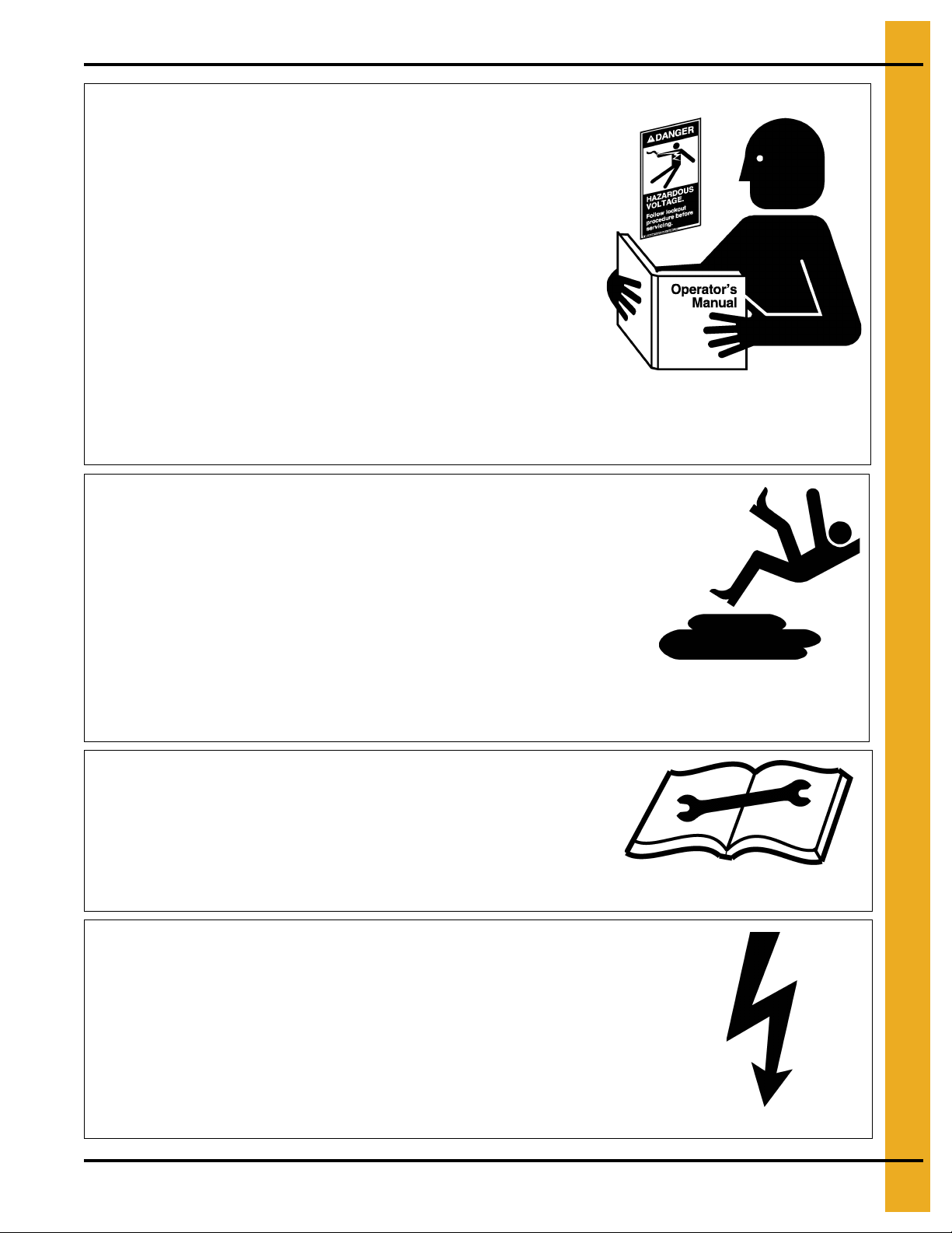
Follow Safety Instructions
Carefully read all safety messages in this manual and
safety signs on your machine. Keep signs in good
condition. Replace missing or damaged safety signs. Be
sure new equipment components and repair parts include
the current safety signs. Replacement safety signs are
available from the manufacturer.
Learn how to operate the machine and how to use controls
properly. Do not let anyone operate without instruction.
Keep your machinery in proper working condition.
Unauthorized modifications to the machine may impair
the function and/or safety and affect machine life.
If you do not understand any part of this manual or need
assistance, contact your dealer.
Read and Understand Manual
Practice Safe Maintenance
Understand service procedures before doing work. Keep area
clean and dry.
Never lubricate, service, or adjust machine while it is in operation.
Keep hands, feet and clothing away from rotating parts.
Keep all parts in good condition and properly installed. Fix
damage immediately . Replace worn or broken p arts. Remove any
built up grease oil and debris.
Maintain Equipment
and Work Area
Install Equipment Properly
This equipment shall be installed in accordance with the
current installation codes and applicable regulations which
should be carefully followed in all cases. Authorities having
jurisdiction should be consulted before installations
are made.
Follow Building Codes
Operate Motor Properly
In an emergency, shut down the power source.
Turn OFF and lock out all power sources before performing
any maintenance.
Do not operate electric motor equipped units until motors are
properly grounded.
Electric Shock Hazard
PNEG-1765 Leeson Motor Field Installation for 7-1/2 HP Load and 7-1/2 HP Unload Applications 5
Page 6

1. Safety
Stay Clear of Rotating Idler
Entanglement in rotating idlers can cause serious
injury or death.
Keep all shields and covers in place at all times.
Wear close fitting clothing. Stop and lock out power
source before making adjustments, cleaning, or
maintaining equipment.
Entanglement Hazard
Wear Protective Clothing
Ear plugs or muffs should be worn at all times to protect ears
from high noise levels.
Wear close fitting clothing and safety equipment appropriate
to the job.
Remove all jewelry.
Long hair should be tied up and back.
Safety glasses should be worn at all times to protect eyes
from debris.
Wear gloves to protect your hands from sharp edges on
plastic or steel parts.
Wear steel toe boots to help protect your feet from falling
debris. Tuck in any loose or dangling shoe strings.
A respirator may be needed to prevent breathing potentially
toxic fumes and dust.
Wear hard hat to help protect your head.
Wear appropriate fall protection equipment when working at
elevations greater than six feet (6').
Eye Protection
Gloves
Steel Toe Boots
Respirator
Hard Hat
Fall Protection
Hearing Protection
6 PNEG-1765 Leeson Motor Field Installation for 7-1/2 HP Load and 7-1/2 HP Unload Applications
Page 7

Top Auger Motor
New sheave
(28138-2)
New motor
(D03-1010)
Revisions for leeson motor
Step 1: (See Figure 2A.)
1. Remove the belts and sheave from the motor shaft.
2. Replace the present 712-1 Baldor motor with the D03-1010 Leeson motor.
3. Install new 28138-2 sheave on motor shaft.
4. Re-install belts and adjust tension.
5. Re-install belt guard.
2. Installation
Figure 2A Top Auger Drive Components
PNEG-1765 Leeson Motor Field Installation for 7-1/2 HP Load and 7-1/2 HP Unload Applications 7
Page 8

2. Installation
New sheave
(28138-2)
New belts
(MHC00793)
New motor
(D03-1010)
Bottom auger drive components
If this is the FFI dryer, replace meter roll pan
lever with D01-2605 before installing new motor.
Bottom auger motor
and motor mount
Bottom Auger Motor
Step 2: (See Figure 2B.)
1. Disassemble auger cleanout handle mechanism to provide easier access to the motor.
2. Remove belts and sheave from motor shaft.
3. If the dryer is an FFI model with 7" metering rolls, replace the meter roll pan lever with D01-2605.
(See Figure 2C on Page 9.) This will resolve any interference with the new motor.
4. Replace the present 712-1 Baldor motor with the D03-1010 Leeson motor.
5. Install new 28138-2 sheave on motor shaft.
6. Install new MHC00793 B84 belts and adjust tension.
Figure 2B
8 PNEG-1765 Leeson Motor Field Installation for 7-1/2 HP Load and 7-1/2 HP Unload Applications
Page 9

2. Installation
New lever
(D01-2605)
Figure 2C
PNEG-1765 Leeson Motor Field Installation for 7-1/2 HP Load and 7-1/2 HP Unload Applications 9
Page 10

2. Installation
Part No./Process
Critical Process/Inspection Parameters
Removal Date:
Issue Date: 7/15/2010
Approval:
Reviewed By: Jeff Falconer
It is imperative that all GSI and FFI cleanout door
brackets be installed on the left side of the
handle as shown.
Cleanout arm must be fastened at both ends on
the left side of the handle.
N5
Cleanout Door
Present assembly
Revise assembly after leeson motor installed
Linkage adjustment bolts
Cleanout Door Mechanism
Step 3: (See Figure 2D below and Figure 2E on Page 11.)
1. To allow adequate clearance between the linkage arm and the motor, move the handle to the left side
of the pivot arm weldment.
2. Also, move the linkage arm to the left side of the cleanout door hinge. (See Figure 2E on Page 11.)
3. Adjust linkage for correct operation of the cleanout door.
Figure 2D
10 PNEG-1765 Leeson Motor Field Installation for 7-1/2 HP Load and 7-1/2 HP Unload Applications
Page 11

2. Installation
Move linkage to
opposite side
Figure 2E Cleanout Door Hinge
PNEG-1765 Leeson Motor Field Installation for 7-1/2 HP Load and 7-1/2 HP Unload Applications 11
Page 12

2. Installation
GSI Group Service Report
12 PNEG-1765 Leeson Motor Field Installation for 7-1/2 HP Load and 7-1/2 HP Unload Applications
Page 13

3. Warranty
9101239_1_CR_rev7.DOC (revised July 2009)
GSI Group, LLC Limited Warranty
The GSI Group, LLC (“GSI”) warrants products which it manufactures to be free of defects in materials and workmanship
under normal usage and conditions for a period of 12 months after sale to the original end-user or if a foreign sale,
14 months from arrival at port of discharge, whichever is earlier. The end-user’s sole remedy (and GSI’s only obligation)
is to repair or replace, at GSI’s option and expense, products that in GSI’s judgment, contain a material defect in materials
or workmanship. Expenses incurred by or on behalf of the end-user without prior written authorization from the GSI
Warranty Group shall be the sole responsibility of the end-user.
Warranty Extensions:
The Limited Warranty period is extended for the following products:
Product Warranty Period
Performer Series Direct Drive Fan Motor 3 Years
AP Fans and Flooring
Cumberland
Feeding/Watering
Systems
Grain Systems Grain Bin Structural Design 5 Years
Grain Systems
Farm Fans
Zimmerman
All Fiberglass Housings Lifetime
All Fiberglass Propellers Lifetime
Feeder System Pan Assemblies 5 Years **
Feed Tubes (1-3/4" and 2.00") 10 Years *
Centerless Augers 10 Years *
Watering Nipples 10 Years *
Portable and Tower Dryers 2 Years
Portable and Tower Dryer Frames and
Internal Infrastructure †
5 Years
* Warranty prorated from list price:
0 to 3 years - no cost to end-user
3 to 5 years - end-user pays 25%
5 to 7 years - end-user pays 50%
7 to 10 years - end-user pays 75%
** Warranty prorated from list price:
0 to 3 years - no cost to end-user
3 to 5 years - end-user pays 50%
† Motors, burner components
and moving parts not included.
Portable dryer screens included.
Tower dryer screens not included.
GSI further warrants that the portable and tower dryer frame and basket, excluding all auger and auger drive components,
shall be free from defects in materials for a period of time beginning on the twelfth (12
and continuing until the sixtieth (60
th
) month from the date of purchase (extended warranty period). During the extended
th
) month from the date of purchase
warranty period, GSI will replace the frame or basket components that prove to be defective under normal conditions of
use without charge, excluding the labor, transportation, and/or shipping costs incurred in the performance of this
extended warranty.
Conditions and Limitations:
THERE ARE NO WARRANTIES THAT EXTEND BEYOND THE LIMITED WARRANTY DESCRIPTION SET FORTH
ABOVE. SPECIFICALLY, GSI MAKES NO FURTHER WARRANTY OF ANY KIND, EXPRESS OR IMPLIED,
INCLUDING, WITHOUT LIMITATION, WARRANTIES OF MERCHANTABILITY OR FITNESS FOR A PARTICULAR
PURPOSE OR USE IN CONNECTION WITH: (I) PRODUCT MANUFACTURED OR SOLD BY GSI OR (II) ANY ADVICE,
INSTRUCTION, RECOMMENDATION OR SUGGESTION PROVIDED BY AN AGENT, REPRESENTA TIVE OR
EMPLOYEE OF GSI REGARDING OR RELATED TO THE CONFIGURATION, INSTALLATION, LAYOUT, SUITABILITY
FOR A PARTICULAR PURPOSE, OR DESIGN OF SUCH PRODUCTS.
GSI shall not be liable for any direct, indirect, incidental or consequential damages, including, without limitation, loss of
anticipated profits or benefits. The sole and exclusive remedy is set forth in the Limited Warranty, which shall not exceed
the amount paid for the product purchased. This warranty is not transferable and applies only to the original end-user. GSI
shall have no obligation or responsibility for any representations or warranties made by or on behalf of any dealer, agent
or distributor.
GSI assumes no responsibility for claims resulting from construction defects or unauthorized modifications to products
which it manufactured. Modifications to products not specifically delineated in the manual accompanying the equipment at
initial sale will void the Limited Warranty.
This Limited Warranty shall not extend to products or parts which have been damaged by negligent use, misuse, alteration,
accident or which have been improperly/inadequately maintained. This Limited Warranty extends solely to products
manufactured by GSI.
Prior to installation, the end-user has the responsibility to comply with federal, state and local codes which apply to the
location and installation of products manufactured or sold by GSI.
PNEG-1765 Leeson Motor Field Installation for 7-1/2 HP Load and 7-1/2 HP Unload Applications 13
Page 14

This equipment shall be installed in accordance with
the current installation codes and applicable
regulations which should be carefully followed in all
cases. Authorities having jurisdiction should be
consulted before installations are made.
Copyright © 2010 by GSI Group
Printed in the USA
GSI Group
1004 E. Illinois St.
Assumption, IL 62510-0020
Phone: 1-217-226-4421
Fax: 1-217-226-4420
www.gsiag.com
 Loading...