

Page 1
PNEG-1758
Competitor/Dri-Tek Control Panel
Operation Manual
PNEG-1758
Date: 07-21-10
Page 2

2 PNEG-1758 Competitor/Dri-Tek Control Panel
Page 3

Table of Contents
Contents
Chapter 1 Competitor/Dri-Tek Control Panel ......................................................................................................4
Dryer Control Panel Featuring the Series 2000 Control System ........................................................... 5
Special Features ....................................... ... .... ... ... ... .......................................................................... 10
Safety Circuit Shutdown Messages .................................................................................................... 10
Chapter 2 Warranty ..............................................................................................................................................15
PNEG-1758 Competitor/Dri-Tek Control Panel 3
Page 4
1. Competitor/Dri-Tek Control Panel
Instructions de Programmation
Programming Instructions
MOISTURE CONTROL
CONTRÔLE D’HUMIDITÉ
LUMIÈRE EN MARCHE (“ON”)
LIGHT “ON”
ON
MARCHE
OFF
ARRÊT
WHEN DISCHARGE MOISTURE ABOVE SETPOINT
Quand l’évacuation d’humidité est au - dessus
du point de consigne
Réglage des minuteries, délais en temps et températures.
Setting timers, time delays and temperatures
Utiliser le mode choisi (select)
Using the mode select
Checking the hour meter
Vérification du Compteur d’Heure
1. Appuyez le bouton du programme que vous désirez changer soit
pour changer l’heure ou soit pour changer la température.
1. Press the button for the program that you wish to
change the time or temperature in.
2. Utilisez les boutons “augmenter” et “diminuer” pour changer
la température ou l’heure présente.
2. Use the increase and decrease buttons to change
the present time or temperature.
3. Après avoir changé l’heure ou la température, l’ordinateur
acceptera automatiquement la nouvelle valeur.
3. After the time or temperature has been changed,
the computer automatically accepts the new value.
1. Pressing the mode select button will toggle the
display between timer values, grain temperature
and plenum temperature.
1. Appuyez le bouton de mode choisi (select) reversera
l’affichage entre les valeurs de temps, la température du
grain et la température du plénum.
Pressing the increase button changes the display
to the total hours on the dryer. It will automatically
return to the main screen after the button is released.
Appuyer sur le bouton “augmenter” changera l’affichage
aux heures totales sur le séchoir. Il retournera automatiquement
à l’écran principal après avoir relâché le bouton.
Turn off and lockout power
before inspection or service.
Hazardous voltage may
cause serious injury
or death.
S’assurer que le courant
électrique soit arrêté et fermé
avant d’inspecter ou de
travailler sur cet équipement.
La tension dangeureuse peut
résulter de blessures graves
ou la mort.
CONTROL POWER
COMMANDE DE PUISSANCE
DRYING MODE
MODE DE SECHAGE
LOAD AUGER
FOREUSE DE CHARGE
STAGED BATCH
GROUPE ETAGÉ
STAGED
BATCH
CONT. FLOW
FLOT CONTINU
GROUPE
ETAGÉ
FLOT
CONTINU
CONT.
FLOW
OFF
ARRÊT
OUTSIDE LIGHT
LUMIÈRE EXTÉRIEURE
ON
MARCHE
ARRÊT
MARCHE
ARRÊT
MARCHE
ARRÊT
ARRÊT
MARCHE
ARRÊT
MARCHE
OFF
VENTILATEUR
FAN
HEATER
RADIATEUR
UNLOAD AUGER
DÉCHARGER LA FOREUSE
DRYER POWER
PUISSANCE DU
SÉCHOIR
START
DÉMARRER
STOP
ARRÊTER
OFF
1 SPEED
VITESSE 1
VITESSE 2
METERING ROLL SPEED
VITESSE DU COMPTEUR
DE ROULEMENT
125
250
2 SPEED
AUTO
OFF
ON
OFF
ON
AUTO
AUTO
AUTO
TIMED
SHUTDOWN
ARRÊT
SYNCHRONISÉ
FAN RUNS EXCEPT
DURING BATCH UNLOAD
LE VENTILATEUR FONCTIONNE
EXCEPTÉ DURANT LE
DÉCHARGEMENT DE LOT
FAN RUNS
CONTINUOUSLY
HEARER “ON”
DURING BATCH DRY
CYCLE ONLY
(LE RADIATEUR EST EN
MARCHE (ON) PENDANT LE
CYCLE DE SÉCHAGE DE
LOT SEULEMENT)
HEATER “ON” WHEN
FAN RUNNING
LOW SPEED
VITESSE LENTE
HIGH SPEED
VITESSE RAPIDE
STAGED BATCH
GROUPE ETAGÉ
CONTINUOUS
CONTINU
ON
OFF
ON
LES VENTILATEURS
FONCTIONNENT
CONTINUELLEMENT
(RADIATEUR EN
MARCHE QUAND LE
VENTILATEUR
FONCTIONNE)
DC-1980
MOISTURE CONTROL SET POINT
POINT DE CONSIGNE DU CONTRÔLE D’HUMIDITÉ
PLENUM TEMPERATURE SET POINT
POINT DE CONSIGNE DE TEMP DE PLÉNUM
HI LO SPEED
VITESSE HAUTE LENTE
DISCHARGE
DÉCHARGE
LO-FLAME
FLAMME BASSE
HI-FLAME
FLAMME HAUTE
PURGE
PURGE
MOTOR
MOTEUR
OVERLOAD
SURCGARGE
ERROR
ERREUR
NO AIRFIOW
PAS D’ÉCOULEMENT D’AIR
% GRAIN
% GRAIN
°F PLENUM
PLÉNUM F
°C HOUSING
BOITÎER C
VAPOR
VAPEUR
TEMP HI-LIMIT
TEMP LIM-ÉLEVÉE
FLAME OUT
FLAMME ÉTEINTE
PROGRAM
(TIMERS)
PROGRAMME
(MINUTERIES)
PROGRAM
(TEMPERATURES)
PROGRAMME
(TEMPÉRATURES)
PROGRAM
(DELAYS)
PROGRAMME
(DÉLAIS)
MODE SELECT
TIMERS/PLENUM TEMP/
GRAIN TEMP
MODE CHOISI (SELECT)
MINUTERIES/TEMP PLÉNUM/
TEMP GRAIN
HOURS
X 1000
HEURES
X 1000
HOURS
HEURES
DC-2004
LOAD DELAY
DÉLAI DE CHARGE
DRY TIME
TEMPS DE SÉCHAGE
OUT OF GRAIN TIME
TEMPS HORS GRAIN
COOL TIME
TEMPS DE REFROIDISSEMENT
UNLOAD TIME
TEMPS DE DÉCHARGE
UNLOAD DELAY
DÉLAI DE DÉCHARGE
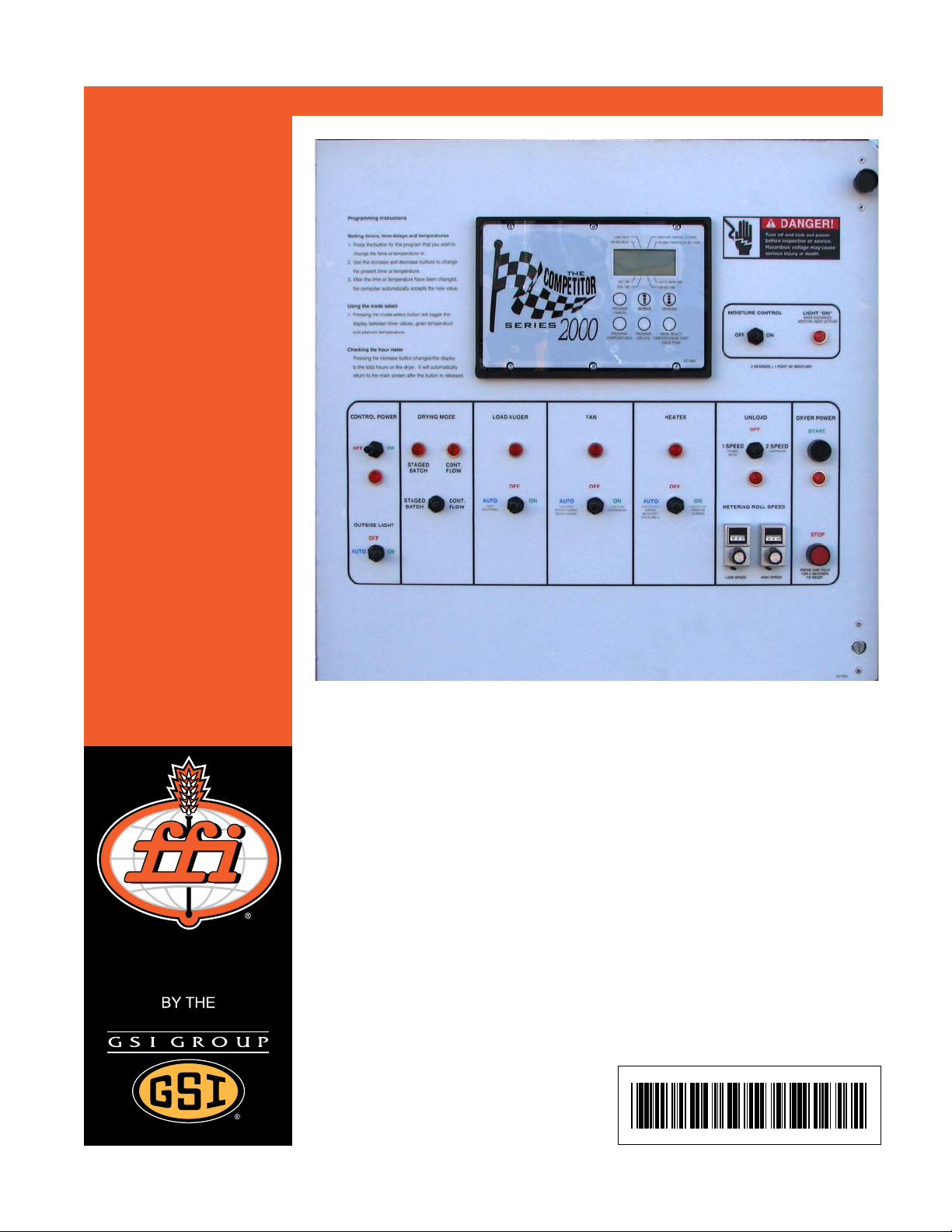
Figure 1A Grain Dryer Control Panel
4 PNEG-1758 Competitor/Dri-Tek Control Panel
Page 5

1. Competitor/Dri-Tek Control Panel
Dryer Control Panel Featuring the Series 2000 Control System
The control panel provides easy access to gauges and controls. The Competitor Series 2000 Control
System is a computerized control system that gives instant information regarding dryer operation.
Moisture Control (Temperature Based)
The Series 2000 dryer has a built in moisture control. It controls the moisture level of discharged grain by
sensing grain column temperature.
Moisture Control Switch
This switch turns the power ON or OFF to the moisture control. The light beside the switch is illuminated
when the grain column temperature is below the moisture control setpoint.
Control Power Switch
The power to the Series 2000 Control System is turned ON or OFF with this switch.
Outside Light
The dryer outside light is turned ON or OFF here.
Drying Mode Switch
This is used to select staged batch or continuous flow drying.
Load Auger Switch
This is used to select the operation of the fill auger. In both the AUTO and MANUAL positions, the load
auger will operate if the dryer is low on grain and will automatically shut off when the dryer is full. In the
AUTO position only, the dryer will shutdown after a preset period of time set on the out of grain timer.
NOTE: If the load auxiliary motor overload relay is being utilized in the dryer control pane l, this switch will
also control the operation of the auxiliary equipment.
Fan Switch
The fan is turned ON or OFF with this switch. The ON position operates the fan continu ously during staged
batch and continuous flow modes. The AUTO position is used in batch mode only and allows the fan to
shutdown during the unloading operation if desired. The light comes ON only when air pressure is sensed.
Heater Switch
This switch is used to turn the burner ON or OFF. The ON position will operate the burner continuously,
but only when the fan is running. The AUTO position is used in batch mode only and allows the heater to
be turned OFF to cool the grain and during the unloading operation. The burner light comes ON only when
flame is detected.
PNEG-1758 Competitor/Dri-Tek Control Panel 5
Page 6

1. Competitor/Dri-Tek Control Panel
Unload Switch
The Unload switch turns the metering rolls and discharge auger ON or OFF and selects the operation of
the metering rolls.
• In the 2 Speed position, if the Moisture Control switch is ON and the Drying Mode switch is turned
to continuous flow, the metering roll speed will alternate between the high speed metering roll
potentiometer setting and the low speed me tering roll potentiometer setting, depending on the
control signal from the moisture control th ermostat. The discharge auger will operate continuously.
• In the 1 Speed position, if the Moisture Control switch is ON and the Drying Mode switch is
turned to continuous flow, the metering roll speed will operate at the high speed metering roll
potentiometer setting or turn OFF depending on the control signal from the moisture control
thermostat. The discharge auger will operate whenever the metering rolls are operating.
• In both the 1 Speed and the 2 Speed positions, if the Moisture Control switch is OFF and the
Drying Mode switch is turned to continuous flow, the metering roll speed can be manually
controlled by adjusting the high speed metering roll potentiometer. The discharge auger will
operate continuously.
• If the Drying Mode switch is turned to staged batch, the Unload switch should be set to the
1 Speed position. The discharge auger and metering rolls will only operate during the unload
cycle of the staged batch operation and the speed of the metering rolls is adjusted using the high
speed metering roll potentiometer.
NOTE: If the unload auxiliary motor overload relay is being utilized in the dryer control panel, the same
switch will also control the operation of the auxiliary equipment.
Low Speed Metering Roll Potentiometer
Use this to adjust the low speed of the metering roll when the 2 Speed automatic moisture control feature
of the dryer is in use.
High Speed Metering Roll Potentiometer
Use this to:
• Set the high speed of the metering roll when the 2 Speed automatic moisture control feature of
the dryer is utilized.
• Set the speed of the metering rolls when the 1 Speed automatic moisture control feature of the
dryer is utilized.
• Set the speed of the metering rolls during continuous flow operation when the moisture control
is not used.
• Set the rate of grain discharge from the dryer during the unload cycle of staged batch
dryer operation.
Dryer Power Start Switch
This switch starts and operates the dryer based on switch settings. If other switch settings are in the OFF
position, individual dryer components can be operated by turning the Drying Mode switch to continuous
flow, pressing the Dryer Power Start button and then turning ON the desired dryer component.
6 PNEG-1758 Competitor/Dri-Tek Control Panel
Page 7

1. Competitor/Dri-Tek Control Panel
Dryer Power Stop Switch
This switch stops all dryer functions. If an automatic dryer shutdown occurs, first determine and correct
the cause of the shutdown. Press the Dryer Power Stop button to reset the dryer before restarting.
Series 2000 Control System
The Series 2000 System controls all timing functions and safety circuit checks. It is designed to simplify
dryer operation by providing messages and warnings on its Liquid Crystal Display (LCD).
Turning ON Series 2000 Control System
Turn the Control Power switch to ON. The monitor will display “GSI” and the current software
version number.
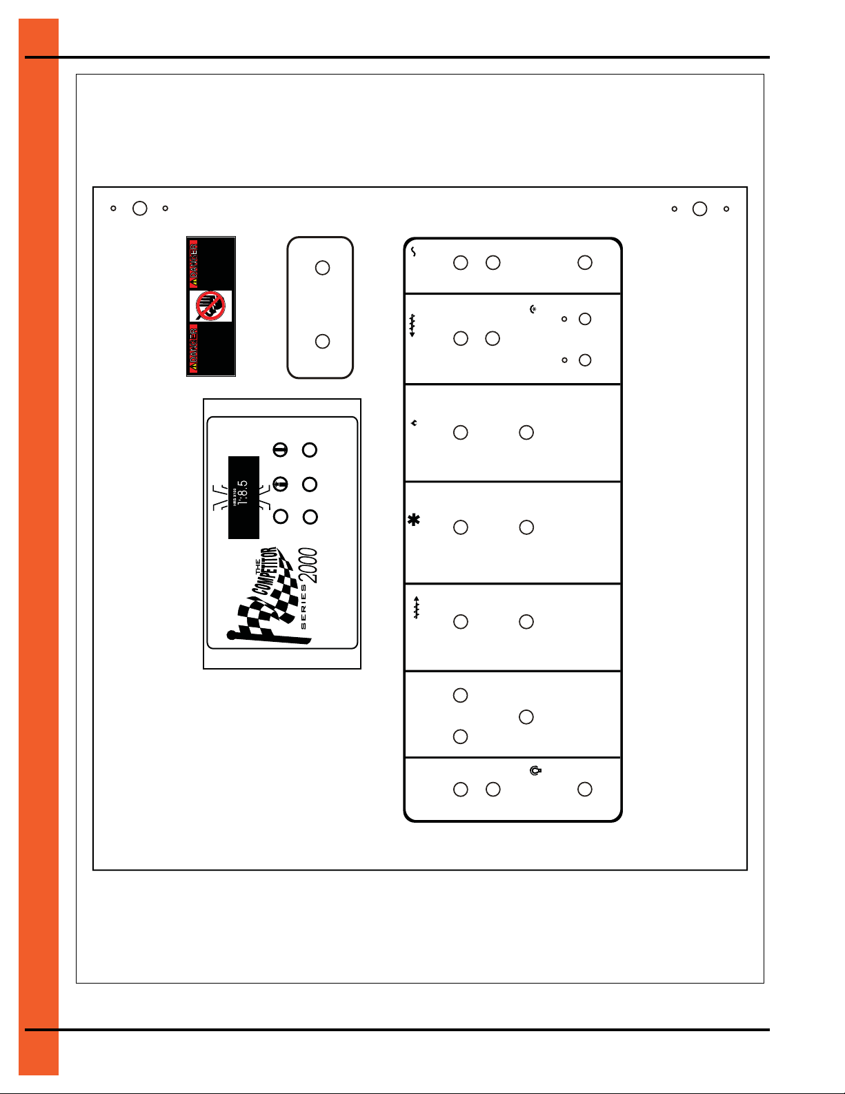
Figure 1B Series 2000 Dryer Control Panel
PNEG-1758 Competitor/Dri-Tek Control Panel 7
Page 8

1. Competitor/Dri-Tek Control Panel
“CARROT”
Setting the Dry, Cool, Unload and Out of Grain Timers
These switches are used to set the drying cycle times in the staged batch drying mode only. The Drying
Mode switch must be in the staged batch position. Out of grain sets the length of time the dryer will run
before shutting down when the Load switch is in the AUTO position. To change the setting of these timers,
follow these instructions:
1. Press the Program (Timers) button until the “carrot” (See Figure 1C) is above the timer you want
to modify.
2. Use the UP and DOWN arrow keys to change from the present time to the desired setting. The new
time is automatically accepted.
3. Keep pressing the Program (Timers) button until the carrot disappears or press the Mode Select
button once to exit.
During the operation, the remaining time on each timer is displayed on the screen. If the power goes out
or if the dryer is stopped, these times are saved by the controller. When the dryer is restarted the timers
will continue timing down. The timers will return to their initial settings by pressing and holding the “Stop”
button for 5 seconds.
Figure 1C Dryer LCD Display
Setting the Load and Unload Delays
The load delay is used to delay the starting of the load auger when the dryer is unloading to prevent the
load auger from starting and stopping too often. The unload delay is used to control the amount of time
the unload auger runs after the metering rolls stop to allow for auger clean out.
1. Press the Program (Delays) button until the carrot is under the time delay to be changed.
2. Use the UP and DOWN arrow keys to change from the present time to the new one. The new time
is automatically entered.
3. Keep pressing the Program (Delays) button until the carrot disappears or press the Mode Select
button once to exit.
8 PNEG-1758 Competitor/Dri-Tek Control Panel
Page 9

1. Competitor/Dri-Tek Control Panel
Setting the Moisture Control and Plenum Setpoint
1. Press the Program (Temperatures) button until the carrot is under the temperature setting to
be changed.
2. Use the UP and DOWN arrow keys to change from the present temperature to the new one. The new
time is automatically entered.
3. Keep pressing the Program (Temperatures) button until the carrot disappears or press the Mode
Select button once to exit.
Dryer Safety Circuit
The Series 2000 Control System continuously checks all safety circuits on the dryer and will automatically
shut the dryer down should a problem occur. The cause of the dryer shutdown will be shown on the LCD
display. To restart the dryer after a safety shutdown, first correct the reason for the shutdown and then
press the Dryer Power Stop button to reset the circuit. Press the Start button.
LOAD DELAY
DÉLAI DE CHARGE
UNLOAD DELAY
DÉLAI DE DÉCHARGE
HI LO SPEED
VITESSE HAUTE LENTE
DISCHARGE
DÉCHARGE
LO-FLAME
FLAMME BASSE
HI-FLAME
FLAMME HAUTE
PURGE
PURGE
MOTOR
MOTEUR
OVERLOAD
SURCGARGE
DRY TIME
TEMPS DE SÉCHAGE
COOL TIME
TEMPS DE REFROIDISSEMENT
PROGRAM
(TIMERS)
PROGRAMME
(MINUTERIES)
PROGRAM
(TEMPERATURES)
PROGRAMME
(TEMPÉRATURES)
ERROR
ERREUR
HOURS
X 1000
HEURES
X 1000
PROGRAM
(DELAYS)
PROGRAMME
(DÉLAIS)
Figure 1D Series 2000 Control System
MOISTURE CONTROL SET POINT
POINT DE CONSIGNE DU CONTRÔLE D’HUMIDITÉ
PLENUM TEMPERATURE SET POINT
POINT DE CONSIGNE DE TEMP DE PLÉNUM
NO AIRFIOW
PAS D’ÉCOULEMENT D’AIR
% GRAIN
% GRAIN
°F PLENUM
PLÉNUM F
°C HOUSING
BOITÎER C
VAPOR
VAPEU R
TEMP HI-LIMIT
TEMP LIM-ÉLEVÉE
FLAME OUT
FLAMME ÉTEINTE
OUT OF GRAIN TIME
TEMPS HORS GRAIN
UNLOAD TIME
TEMPS DE DÉCHARGE
HOURS
HEURES
MODE SELECT
TIMERS/PLENUM TEMP/
GRAIN TEMP
MODE CHOISI (SELECT)
MINUTERIES/TEMP PLÉNUM/
TEMP GRAIN
DC-2004
Monitoring Grain Temperatures, Plenum Temperature or Timers
Use the mode select to decide which of the modes you want to view.
Checking the Hour Meter
Press the UP arrow key and the total hours on the machine are displayed along with the batch count and
minutes since the last shutdown in five (5) successive screens. The screens appear in the following order:
Hours X 100, balance of hours, balance of minutes, batch count and minutes since last shutdown.
For example, five (5) screens displaying 5 | 23 | 12 | 144 | 188 would be: 523 Hours, 12 minutes on the
Hour Meter, Batch Count at 144 and 188 minutes since the last shutdown.
PNEG-1758 Competitor/Dri-Tek Control Panel 9
Page 10

1. Competitor/Dri-Tek Control Panel
Special Features
Dual Batch Drying Temperature Mode
To greatly improve quality in batch mode, reduce the plenum temperature at the end of the
drying cycle. This will reduce peak temperature that the grain on the inside of the column
attains and thereby reduce over-drying.
Enter dual batch drying temperature mode by switching ON dipswitch number four (#4), the
fourth switch from the bottom, on the dipswitches located inside the control box on
the back of the computer control board. This enables two (2) plenum and two (2) grain
temperature settings, high and low. Set these parameters the same way the single p lenum
and grain temperature settings are made. The first of each temperatures being set will be
the low setting and will be indicated by the word “Low” on the screen. The second setting
will be identified by “High” on the display screen.
Typically, the plenum settings would be 170 for low and 230 for high and the low grain
temperature setting would be 10° to 20° below the normal moisture control temperature
setting which becomes the new high setting.
Both capacity and quality will improve using this feature while operating in batch dry and
cool or all heat modes.
Emergency Cooling Mode
To enter an emergency cooling mode, switch ON switch number seven (#7), which is the
second switch from the top on the dipswitch inside of the control box on the back of the
computer control board. This initiates a mode in which only the dryer fan runs, in case there
is a plenum temperature or grain high-limit warning. When either of these safeties shuts
down the dryer, run the fan to help cool the grain and/or plenum high-limit back down to a
safe level. After flipping the switch, press the Start button and only the fan will run for
approximately five minutes.
Burner ON/OFF Operation
Due to changing fuel conditions and to aid in drying wheat and other low temperature grains in hot
weather, an ON/OFF burner has been developed in recent years.
By moving the third switch, number six (#6), on the dipswitch located inside the control box on the back of
the computer control board to ON, the burner can be changed from a high-low burner to an ON/OFF
burner. The burner will operate exactly the same as the high-low burner, however, when the setpoint is
reached, the burner cycles OFF instead of switching to a lower pressure. The vaporizer cools much more
quickly and allows a closer tolerance on the setpoint and to operate at lower temperature rises.
Safety Circuit Shutdown Messages
Vapor High Temperature
This shutdown message indicates that the LP gas vapor temperature sensor, located in the gas pipe train
downstream from the vaporizer has opened. This indicates that the vaporizer is running too hot and must
be readjusted. This sensor is set at 200°F and automatically resets itself when cool.
10 PNEG-1758 Competitor/Dri-Tek Control Panel
Page 11

1. Competitor/Dri-Tek Control Panel
Loss of Flame
The flame sensor failed to detect a burner flame, indicating that the burner has failed to light. There is a
problem with the flame sensing circuitry or the dryer is not getting burner fu el. The burner switch light will
be lit any time flame has been sensed by the burner controls.
Housing High Temperature
The temperature high-limit, located on the fan /heater housing has opened, indicating an over temperature
condition has occurred toward the rear of the fan/heater housing in a n oblong covered electrical box. This
control is set at 200°F and MUST BE MANUALLY RESET.
Rear Discharge Warning
The lid on the grain discharge box has opened, indicating that grain is not being taken away fast enough
at the discharge box.
Motor Overload
One of the thermal overloads on either the fan, load, unload or auxiliary motors has opened, indicating an
over current condition. The overloads MUST BE MANUALLY RESET.
Grain High Temperature
An over temperature condition has occurred in one of the grain columns, causing the control to shutdown
the dryer. This control is set at 210°F and automatically resets itself when cool.
Out of Grain
The dryer has run low on grain and the out of grain timer has timed out, shutting the dryer down. The
unload auger will clean out the dryer if in continuous flow operation.
Plenum High Temperature
An over temperature condition has occurred inside the dryer plenum. This control is a 300°F limit and
automatically resets itself when cool. See Emergency Cooling Mode on Page 10.
No Airflow
The contacts in the Air switch have opened due to insufficient airflow for the burner to operate. The
contacts in the Air switch have opened due to the fan not turning or the Air switch may need adjusting.
Air
The Air switch contacts have closed prior to the fan starting, indicating a free wheeling blade or improper
setting of the Air switch.
Grain and Plenum High Temperature (Both at Same Time)
If both of these warnings appear on the screen at the same time, one of the two (2) mechanical high-limits,
located in each of the two (2) grain columns, has been tripped due to heat exceeding their 200° setpoint
or one or both have failed. They will automatically reset when the temperature returns below 200°.
NOTE: The emergency cooling feature will not function if either or both of these mechanical sensors
are tripped.
PNEG-1758 Competitor/Dri-Tek Control Panel 11
Page 12

1. Competitor/Dri-Tek Control Panel
Error Conditions
Figure 1E
12 PNEG-1758 Competitor/Dri-Tek Control Panel
Page 13

1. Competitor/Dri-Tek Control Panel
Figure 1F
PNEG-1758 Competitor/Dri-Tek Control Panel 13
Page 14

NOTES
14 PNEG-1758 Competitor/Dri-Tek Control Panel
Page 15

2. Warranty
9101239_1_CR_rev7.DOC (revised July 2009)
GSI Group, LLC Limited Warranty
The GSI Group, LLC (“GSI”) warrants products which it manufactures to be free of defects in materials and workmanship
under normal usage and conditions for a period of 12 months after sale to the original end-user or if a foreign sale,
14 months from arrival at port of discharge, whichever is earlier. The end-user’s sole remedy (and GSI’s only obligation)
is to repair or replace, at GSI’s option and expense, products that in GSI’s judgment, contain a material defect in materials
or workmanship. Expenses incurred by or on behalf of the end-user without prior written authorization from the GSI
Warranty Group shall be the sole responsibility of the end-user.
Warranty Extensions:
The Limited Warranty period is extended for the following products:
Product Warranty Period
Performer Series Direct Drive Fan Motor 3 Years
AP Fans and Flooring
Cumberland
Feeding/Watering
Systems
Grain Systems Grain Bin Structural Design 5 Years
Grain Systems
Farm Fans
Zimmerman
All Fiberglass Housings Lifetime
All Fiberglass Propellers Lifetime
Feeder System Pan Assemblies 5 Years **
Feed Tubes (1-3/4" and 2.00") 10 Years *
Centerless Augers 10 Years *
Watering Nipples 10 Years *
Portable and Tower Dryers 2 Years
Portable and Tower Dryer Frames and
Internal Infrastructure †
5 Years
* Warranty prorated from list price:
0 to 3 years - no cost to end-user
3 to 5 years - end-user pays 25%
5 to 7 years - end-user pays 50%
7 to 10 years - end-user pays 75%
** Warranty prorated from list price:
0 to 3 years - no cost to end-user
3 to 5 years - end-user pays 50%
† Motors, burner components
and moving parts not included.
Portable dryer screens included.
Tower dryer screens not included.
GSI further warrants that the portable and tower dryer frame and basket, excluding all auger and auger drive components,
shall be free from defects in materials for a period of time beginning on the twelfth (12
and continuing until the sixtieth (60
th
) month from the date of purchase (extended warranty period). During the extended
th
) month from the date of purchase
warranty period, GSI will replace the frame or basket components that prove to be defective under normal conditions of
use without charge, excluding the labor, transportation, and/or shipping costs incurred in the performance of this
extended warranty.
Conditions and Limitations:
THERE ARE NO WARRANTIES THAT EXTEND BEYOND THE LIMITED WARRANTY DESCRIPTION SET FORTH
ABOVE. SPECIFICALLY, GSI MAKES NO FURTHER WARRANTY OF ANY KIND, EXPRESS OR IMPLIED,
INCLUDING, WITHOUT LIMITATION, WARRANTIES OF MERCHANTABILITY OR FITNESS FOR A PARTICULAR
PURPOSE OR USE IN CONNECTION WITH: (I) PRODUCT MANUFACTURED OR SOLD BY GSI OR (II) ANY ADVICE,
INSTRUCTION, RECOMMENDATION OR SUGGESTION PROVIDED BY AN AGENT, REPRESENTA TIVE OR
EMPLOYEE OF GSI REGARDING OR RELATED TO THE CONFIGURATION, INSTALLATION, LAYOUT, SUITABILITY
FOR A PARTICULAR PURPOSE, OR DESIGN OF SUCH PRODUCTS.
GSI shall not be liable for any direct, indirect, incidental or consequential damages, including, without limitation, loss of
anticipated profits or benefits. The sole and exclusive remedy is set forth in the Limited Warranty, which shall not exceed
the amount paid for the product purchased. This warranty is not transferable and applies only to the original end-user. GSI
shall have no obligation or responsibility for any representations or warranties made by or on behalf of any dealer, agent
or distributor.
GSI assumes no responsibility for claims resulting from construction defects or unauthorized modifications to products
which it manufactured. Modifications to products not specifically delineated in the manual accompanying the equipment at
initial sale will void the Limited Warranty.
This Limited Warranty shall not extend to products or parts which have been damaged by negligent use, misuse, alteration,
accident or which have been improperly/inadequately maintained. This Limited Warranty extends solely to products
manufactured by GSI.
Prior to installation, the end-user has the responsibility to comply with federal, state and local codes which apply to the
location and installation of products manufactured or sold by GSI.
PNEG-1758 Competitor/Dri-Tek Control Panel 15
Page 16

This equipment shall be installed in accordance with
the current installation codes and applicable
regulations which should be carefully followed in all
cases. Authorities having jurisdiction should be
consulted before installations are made.
Copyright © 2010 by GSI Group
Printed in the USA
1004 E. Illinois St.
Assumption, IL 62510-0020
Phone: 1-217-226-4421
Fax: 1-217-226-4420
www.gsiag.com
 Loading...