

Page 1
PLC WatchDog
Installation and Operation Manual
PNEG-1755
Date: 07-28-10
PNEG-1755
Page 2

2 PNEG-1755 PLC WatchDog
Page 3

Table of Contents
Contents
Chapter 1 Safety ..................................................................................................................................................... 4
Safety Guidelines .................................................................................................................................. 4
Dryer Operation ..................................................................................................................................... 5
Emergency Stop Switch ................................... ... ... ... .... ... ... ... .... ... ... ..................................................... 5
Safety Precautions .................................... ... .... .......................................... ... ........................................ 6
Chapter 2 Introduction .......................................................................................................................................... 8
Description ............................................................................................................................................ 8
Features ................................................................................................................................................ 8
Chapter 3 Installation ............................................................................................................................................ 9
PLC WatchDog Connection ................................................................................................................... 9
Package Contents ........................................................................................................................... 9
Install Procedure ............................................................................................................................ 10
Network Setup ............................................................................................................................... 10
Configuring a Modem/Router ................ ... ... .... ... ... ... .... ... .......................................... ... ... ... .... 10
DHCP Reservations ........................................................................................................ 10
DHCP Pool ......................................................................................................................11
Accessing the PLC WatchDog ...................................................................................................... 11
Chapter 4 PLC WatchDog Operation ................................................................................................................. 12
GSI PLC WatchDog ............................................................................................................................ 12
View Data ............................................................................................................................................ 12
Password ...................................... ................................ .................................... ............................. 13
PLC WatchDog .............................................................................................................................. 14
Set Time and Date ........................................... ... .... ... ... ... .... ......................................... .... ............. 15
Editing Variables ............................................................................................................................ 16
View Logs ............................................................................................................................................ 17
Remote View ................................................................. ... ... ... .... ... ... ... ... ............................................. 19
Editing Passwords ......................................................................................................................... 19
Verify Password Button ................................................................................................................. 21
Password Status Indicator ......................................................................................................21
Change Password Button .............................................................................................................. 22
Dryer Display Button .................................. ... ... ... .... ... ... ... .... ... .......................................... ............. 24
Main Display ... .......................................... ... .......................................... .... ............................. 24
Stop Button ............................................................................................................................. 24
Auto/Manual Button ................................................................................................................ 24
Email On/Off Button ............................................................................................................... 24
Main Menu Button .......... .... ... .......................................... ... .......................................... ... ....... 25
Log Off Button ................ .... ... .......................................... ... .......................................... .......... 25
System Variables Button ............................................................................................................... 25
Email Settings Button ................ ... ... ... .......................................... ... .............................................. 26
Time Settings Button ..................................................................................................................... 27
Chapter 5 Troubleshooting ................................................................................................................................. 29
Chapter 6 Technical Support .............................................................................................................................. 30
Chapter 7 Appendix A ......................................................................................................................................... 31
Acquiring and Installing a BlueTree Cellular Modem .......................................................................... 31
Chapter 8 Appendix B ......................................................................................................................................... 32
Common List of SMS Carriers and Account Formatting ..................................................................... 32
Chapter 9 Appendix C ......................................................................................................................................... 33
Chapter 10 Warranty ............................................................................................................................................ 35
PNEG-1755 PLC WatchDog 3
Page 4
1. Safety
This is the safety alert symbol. It is used to alert you to
potential personal injury hazards. Obey all safety
messages that follow this symbol to avoid possible
injury or death.
WARNING indicates a potentially hazardous situation
which, if not avoided, could result in death or serious injury.
CAUTION indicates a potentially hazardous situation which,
if not avoided, may result in minor or moderate injury.
CAUTION used without the safety alert symbol indicates a
potentially hazardous situation which, if not avoided, may
result in property damage.
NOTE indicates information about the equipment that you
should pay special attention.
DANGER indicates an imminently hazardous situation
which, if not avoided, will result in death or serious injury.
Personnel operating or working around electric fans should read this manual. This manual
must be delivered with the equipment to its owner. Failure to read this manual and its
safety instructions is a misuse of the equipment.
WARNING! BE ALERT!
Safety Guidelines
This manual contains information that is important for you, the owner/operator, to know and understand.
This information relates to protecting personal safety and preventing equipment problems. It is the
responsibility of the owner/operator to inform anyone operating or working in the area of this equipment of
these safety guidelines. To help you recognize this information, we use the symbols that are defined
below. Please read the manual and pay attention to these sections. Failure to read this manual and its
safety instructions is a misuse of the equipment and may lead to serious injury or death.
4 PNEG-1755 PLC WatchDog
Page 5
1. Safety
Dryer Operation
Thank you for choosing a GSI product. It is designed to give excellent performance and service for
many years.
This manual describes the operation and service for all standard production model dryers. T hese models
are available for liquid propane or natural gas fuel supply, with either 1 phase 230 volt, or 3 phase
230 or 440 volt electrical power.
Our foremost concern is your safety and the safety of others associated with this equipment. We want to
keep you as a customer. This manual is to help you understand safe operating procedures and some
problems which may be encountered by the operator and other personnel.
As owner and/or operator, it is your responsibility to know what requirements, hazards and precautions
exist, and to inform all personnel associated with the equipment or in the area. Safety precautions may be
required from the personnel. Avoid any alterations to the equipment. Such alterations may produce a very
dangerous situation where SERIOUS INJURY or DEATH may occur.
This equipment shall be installed in accordance with the current installation codes and applicable
regulations which should be carefully followed in all cases. Authorities having jurisdiction should be
consulted before installations are made.
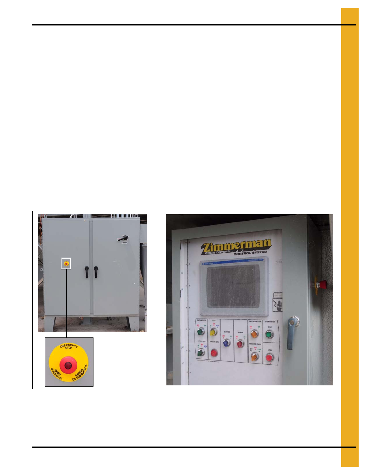
Emergency Stop Switches
The Emergency Stop switches are located on the power panel and the control panel. Pushing the
Emergency Stop switches will interrupt the control power and stop all dryer functions.
Pushing the Emergency Stop Switches does not interrupt the main power to the power panel.
PNEG-1755 PLC WatchDog 5
Page 6

1. Safety
Safety Precautions
READ THESE INSTRUCTIONS BEFORE INSTALLATION AND OPERATION
SAVE FOR FUTURE REFERENCE
1. Read and understand the operating manual before attempting to operate the dryer.
2. NEVER operate the dryer while the guards are removed.
3. Power supply should be OFF for service of electrical components. Use CAUTION in checking voltage
or other procedures requiring the power to be ON.
4. Check for gas leaks at all gas pipe connections. If any leaks are detected,
Shutdown and repair before further operation.
5. NEVER attempt to operate the dryer by jumping or otherwise bypassing any safety devices on
the unit.
6. Set pressure regulator to avoid excessive gas pressure being applied to the burner during ignition
and when the burner is in operation. DO NOT exceed maximum recommended drying temperature.
7. Keep the dryer clean. DO NOT allow fine material to accumulate in the plenum chamber.
Clean grain is easier to dry. Fine material increases resistance to airflow and requires removal
of extra moisture.
8. Keep auger drive belts tight enough to prevent slippage.
9. Use CAUTION in working around high speed fans, gas burners, augers and auxiliary conveyors
which can START AUTOMATICALLY.
10. Keep area around air inlet to the fan clear of any obstacles and combustible materials.
11. BEFORE attempting to remove and reinstall any propeller, make sure to read the
recommended procedure.
12. Make sure that capacities of auxiliary conveyors are matched to dryer auger capacities.
13. DO NOT operate in an area where combustible material will be drawn into the fan.
DO NOT
operate dryer.
14. The operating and safety recommendations in this manual pertain to the common cereal
grains as indicated. When drying any other grain or products, consult the factory for
additional recommendations.
15. Routinely check for any developing gas plumbing leaks. Check LP vaporizer for contact with
burner vanes.
6 PNEG-1755 PLC WatchDog
Page 7

1. Safety
Use Caution in the Operation of this Equipment
This dryer is designed and manufactured with operator safety in mind. However, the very nature of a
grain dryer having a gas burner, high voltage electrical equipment and high speed rotating parts, presents
hazards to personnel which cannot be completely safeguarded against without interfering with the efficient
operation of the dryer and reasonable access to its components.
Use extreme caution in working around high speed fans, gas-fired heaters, augers and auxiliary conveyors,
which may start without warning when the dryer is operating on automatic control.
Continued safe, dependable operation of automatic equipment depends, to a great degree, upon the
owner. For a safe and dependable drying system, follow the recommendations within the Owner’s Manual
and make it a practice to regularly inspect the unit for any developing problems or unsafe conditions.
Take special note of the Safety Precautions on Page 6 before attempting to operate the dryer.
PNEG-1755 PLC WatchDog 7
Page 8

2. Introduction
Description
The PLC WatchDog system allows for remote monitoring of a tower dryer.
An internet connection allows the user to view the dryer from any device that has a web browser. Currently,
the only supported browser is Microsoft’s Internet Explorer.
Features
1. Remote monitoring of dryer
2. Remote shutdown of dryer
3. Remote drying parameter adjustment (Plenum and grain temperature setpoints, unload rate, etc.)
4. Web browser is the only software needed by the customer
5. Text message and/or email can be sent to alert customers of shutdowns
8 PNEG-1755 PLC WatchDog
Page 9
3. Installation
1
2
3
4
PLC WatchDog Connection (Part #: GT4-5073)
This requires an active internet connection be present at the dryer via Ethernet (RJ-45 connection). It is
recommended that either an Internet Service Provider (ISP) technician or someone versed in networking
be present during installation. While GSI’s Technical Support group can offer sugg estions, GSI is not
responsible for the required connection.
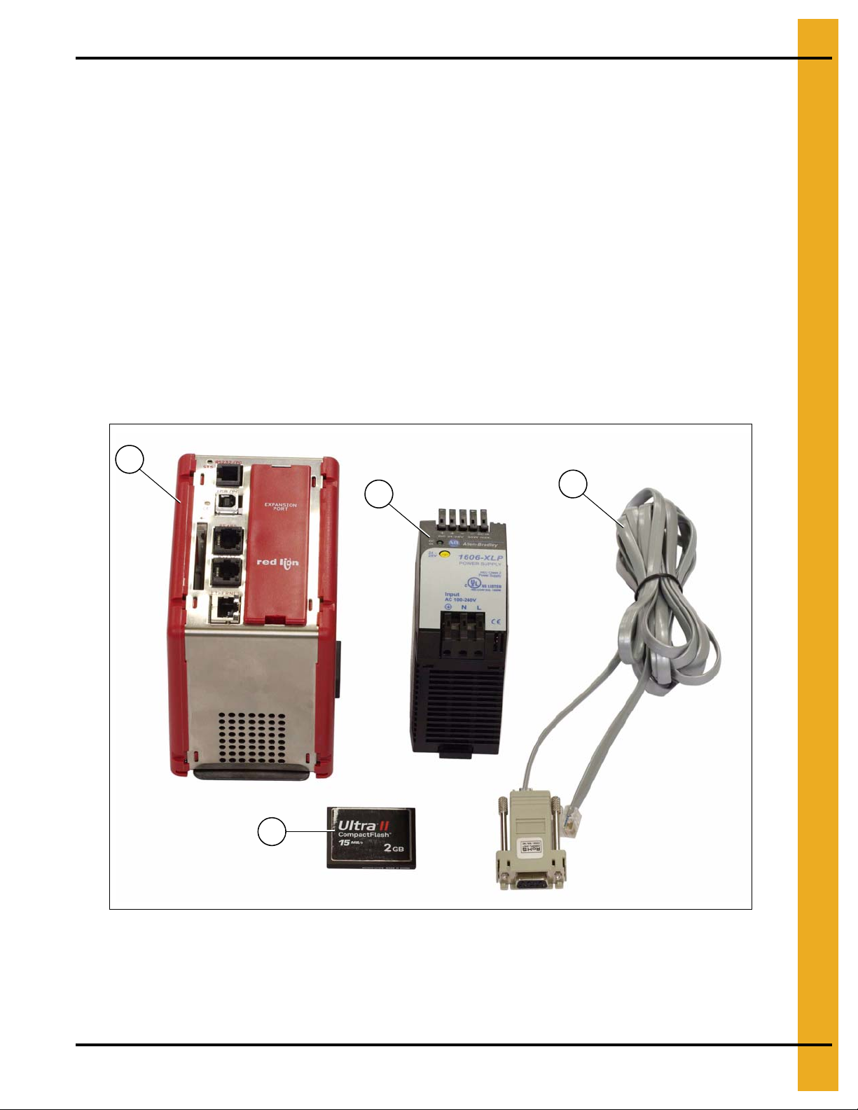
Package Contents
The contents of this package are pictured in Figure 3A. Please refer to Figure 3A during installation.
Package contains:
1. Red Lion Controller
2. 24 VDC Power Supply
3. CF memory card
4. Cable #CBLAB001
Figure 3A
PNEG-1755 PLC WatchDog 9
Page 10

3. Installation
Install Procedure
This installation takes place in the power panel of the tower dryer system. Follow the steps listed below to
install the components; also refer to Figure 3A on Page 9.
1. Turn OFF power to the dryer and control panel.
2. Attach the Red Lion controller and the 24 VDC power supply to the DIN rail.
3. Wire the 120 VAC supply power from the power panel terminal “L1.1”, to the 24 VDC power supply
terminal “L”.
4. Wire the white NEUTRAL wire from the power panel terminal “L2”, to the 24 VDC power supply
terminal “N”.
5. Wire the GROUND from the power panel terminal strip, to the 24 VDC power supply terminal “ ”.
6. Wire the 24 VDC power supply terminal “+”, to the Red Lion terminal “+24”.
7. Wire the 24 VDC power supply terminal “-”, to the Red Lion terminal “COMM”.
8. If a cellular modem is being installed, first refer to Appendix A on Page 31 for additional instructions
and then return here.
9. Plug the RJ12 end of the Pacific Cable #CBLAB001 into the RS232 port of the Red Lion controller
and the DB9 end into the SLC serial port.
10. Plug the Ethernet cable with a live internet connection into the ETHERNET port on the Red
Lion controller.
NOTE: Use cable ties to secure wires.
11. Turn ON power to the dryer and the power panel. A green LED should illuminate on the 24 VDC
power supply indicating power.
12. A green LED, labeled “STS”, should illuminate on the Red Lion unit indicating the controller is
operating properly.
13. A red LED, labeled “CF”, should illuminate verifying a valid CompactFlash card is installed.
Network Setup
This section is intended to help ISP or network technicians install the PLC WatchDog. If this section does
not make sense to you, it is strongly advised to request the service of a network technician.
SECURITY NOTE: Ultimately, it is the End User’s responsibility to make sure the PLC WatchDog is
properly placed behind a secured network security system.
Configuring a Modem/Router
If the PLC WatchDog is connected to a modem/router that is configurable, listed below are a few
recommendations to assist with setup. The methods below do not cover every configuration that
is available.
DHCP Reservations
This is the preferred method for installation. A reservation can be an option in the configuration of a
modem/router. It can be set to serve a given MAC address with a certain IP address when it is introduced
to the network. As mentioned above, the MAC address of the PLC WatchDog can be found on a label on
the front of the Red Lion controller.
Once the IP address has been setup for the MAC address, forward incoming requests on ports 21 and 80.
10 PNEG-1755 PLC WatchDog
Page 11
3. Installation
DHCP Pool
If the modem/router does not have DHCP reservations, the controller can be allowed to pull an IP address
from the DHCP server’s IP range. This method is only recommended when the PLC WatchDog is the only
node on the network.
Reduce the IP range of the DHCP server down to one IP address. This will be the only IP address that the
DHCP server is allowed to serve to the network. Once the range has been narrowed to one, forward
incoming requests on ports 21 and 80 to the single IP address.
Accessing the PLC WatchDog
The tower dryer PLC WatchDog is accessed from any PC that has an internet connection and web
browser. Some phones are available that view the graphics correctly.
1. Make sure that the dryer is powered up and the PLC application is running.
2. On the PC or phone, open up a web browser, i.e. Internet Explorer.
3. In the URL bar, enter the IP address given by your network administrator. There is no need to put
“www”, simply enter the number sequence. The IP address shown in the Figure 3B is just for
illustration purposes. The IP address you enter will be different.
4. The “GSI PLC WatchDog” should now appear. If it does not, run back through the install procedure
to verify everything is connected properly.
Figure 3B
5. Once the “GSI PLC WatchDog” appears, move on to Chapter 4 “PLC WatchDog Operation”
on Page 12.
PNEG-1755 PLC WatchDog 11
Page 12

4. PLC WatchDog Operation
GSI PLC WatchDog
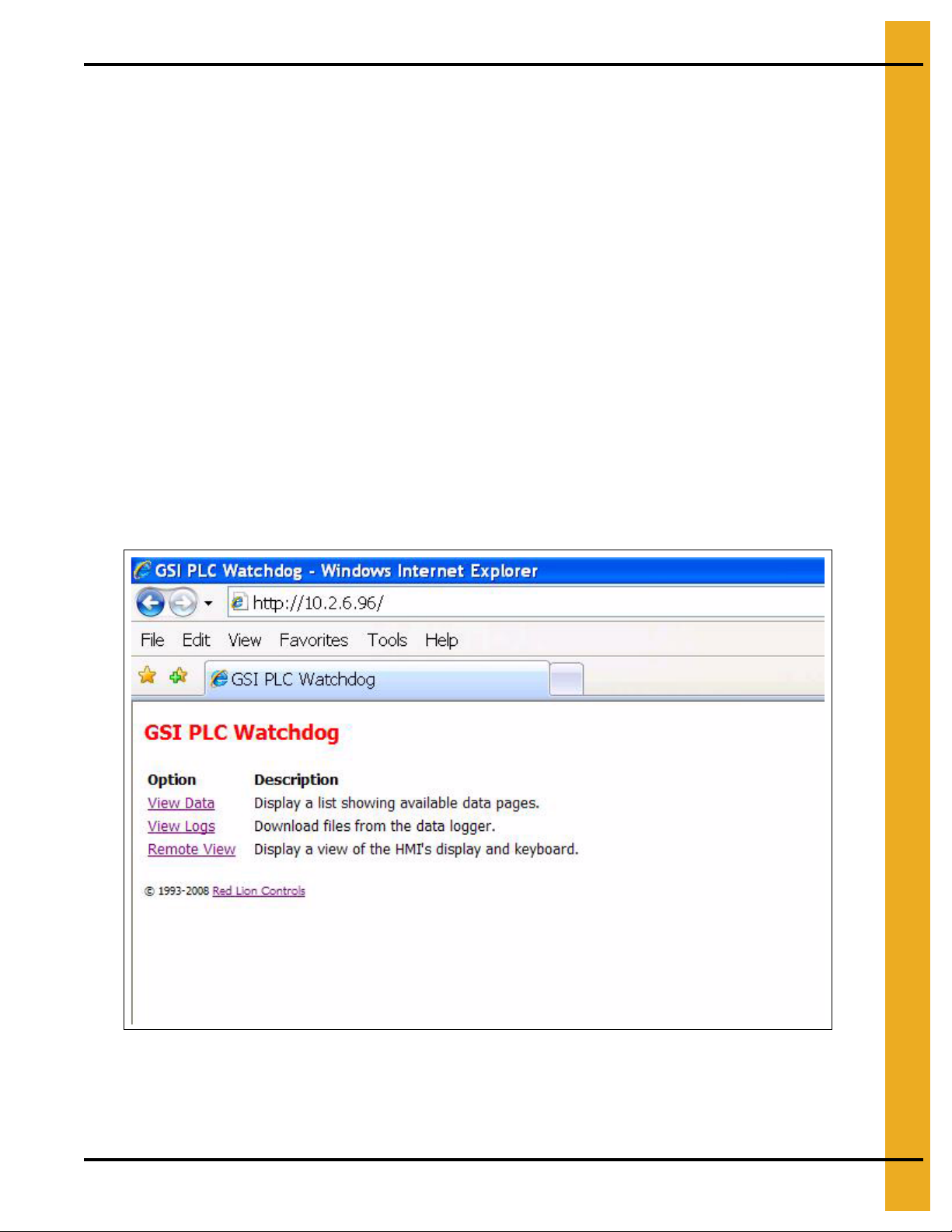
When the web browser initially makes contact with the PLC WatchDog System, you will be presented with
a screen displaying several links to other pages. (See Figure 4A.)
Figure 4A
From this page you may access the “View Data”, “View Logs” and “Remote View” pages.
View Data
The following pages allow the user to input data to be changed with the Remote View application.
(See Figure 4B.)
Figure 4B
12 PNEG-1755 PLC WatchDog
Page 13

Password
4. PLC WatchDog Operation
Figure 4C
Variables that may be edited here are: (See Figure 4C.)
Enter Current Password - Enter current password to be verified.
New Password - Enter only when changing passwords.
Re-Enter New Password - Enter only when changing passwords.
For additional information on verifying and changing your password information, refer to “Remote View”
section on Page 19 of this manual.
PNEG-1755 PLC WatchDog 13
Page 14

4. PLC WatchDog Operation
PLC WatchDog
Figure 4D
Variables that may be edited here are: (See Figure 4D.)
IP Address - Address that the SMTP server is using to forward messages.
SMTP Domain - Domain name of SMTP server.
Email User - Email address to receive alarm messages.
SMS Text User - Text messaging account information*.
Grain Temp - °F setpoint for grain temperature.
Unload Rate - Speed setpoint for unload conveyor.
Dry Setpoint - Percent moisture setpoint for dry grain.
Plenum Temp - °F setpoint for plenum temperature.
Test Other Email - Turn “ON” for testing new email and text account settings.
For additional information on updating the PLC with new variable information, refer to Remote View System Variables on Page 25 and Email Settings section on Page 26 of this manual.
*For a list of common SMS carriers and their account formatting, see Appendix B on Page 32.
14 PNEG-1755 PLC WatchDog
Page 15

Set Time and Date
4. PLC WatchDog Operation
Figure 4E
These variables allow the user to modify the date that the PLC stores. This information is also displayed
on the Remote View Dryer Display. (See Figure 4E.)
System Month - Month of the year stored in the PLC.
System Day - Day of the week stored in the PLC.
System Year - Current year to be stored in the PLC.
System Hour - Hour of the day stored in the PLC.
System Minute - Minute of the hour stored in the PLC.
For additional information on updating the PLC with new variable information, refer to Remote View Time Settings section on Page 27 of this manual.
PNEG-1755 PLC WatchDog 15
Page 16

4. PLC WatchDog Operation
Editing Variables
All of the previous listed variables can be changed by the following instructions; we will use Grain Temp
as an example.
Navigate to the GSI PLC WatchDog web page. - (See Figure 4A on Page 12.)
Select “View Data”. - (See Figure 4B on Page 12.)
Select “PLC WatchDog”. - (See Figure 4D on Page 14.)
Select “Edit” next to the Grain Temp variable.
In the box labeled “New Value”, enter your new setpoint.
Figure 4F
Click “OK”. (See Figure 4F.)
You will be re-directed back to the “PLC WatchDog” on Page 14.
Verify your new Grain Temp setpoint is listed as the “Value”. (See Figure 4G on Page 17.)
16 PNEG-1755 PLC WatchDog
Page 17

4. PLC WatchDog Operation
Figure 4G
Select “Back” to return to the “View Data” web page. (See Figure 4B on Page 12.)
Select “Back” to return to the “GSI PLC WatchDog” web page. (See Figure 4A on Page 12.)
When editing variables, several may be edited before navigating to the “Remote View” page. Therefore
perform as many edits as you need before returning to update any variables or settings.
View Logs
The following pages allow the user to view a directory of available logs based on the control mode of the
dryer. Select the mode the dryer is operating and you will have a collection of CSV files on the history of
the dryer. (See Figure 4H on Page 18.)
PNEG-1755 PLC WatchDog 17
Page 18

4. PLC WatchDog Operation
Figure 4H
For example, if the dryer is running a TWOPOINT control then you would select the TWOPOINT link and
the file list will be displayed. (See Figure 4I.)
Figure 4I
These files may then be downloaded and saved for future use by the user. These files are easily opened
in Microsoft Excel and can be manipulated to show historical data from the dryer.
18 PNEG-1755 PLC WatchDog
Page 19

4. PLC WatchDog Operation
Remote View
The “Remote View” web page allows the customer remote access to view and modify certain variables
and information for the dryer. (See Figure 4J.)
Figure 4J
To continue any further, the user will need to verify a password. This password must be entered into the
“Enter Current Password” field on the “View Data - Password” web page.
Editing Passwords
Navigate to the “GSI PLC WatchDog” web page. - (See Figure 4A on Page 12.)
Select “View Data”. - (See Figure 4B on Page 12.)
Select “Password”. - (See Figure 4C on Page 13.)
Select “Edit” next to the “Enter Current Password” variable.
In the box labeled “New Value”, enter your current password.
PNEG-1755 PLC WatchDog 19
Page 20

4. PLC WatchDog Operation
Figure 4K
Click “OK”. (See Figure 4K.)
You will be re-directed back to the “Password” page.
Verify your current password is now listed as the “Value”. (See Figure 4L.)
Figure 4L
Select “Back” to return to the “View Data” web page. (See Figure 4B on Page 12.)
Select “Back” to return to the “GSI PLC WatchDog” web page. (See Figure 4A on Page 12.)
20 PNEG-1755 PLC WatchDog
Page 21

4. PLC WatchDog Operation
Verify Password Button
Pressing the “Verify Password” button with a valid password entered will change the “Password Status”
indicator from “Inactive”, Figure 4J on Page 19, to “Active” as in Figure 4M.
Figure 4M
Password Status Indicator
An “Active” status allows the user to access other areas of the “Remote View” program. The user may
edit variables in the “View Data” section of the interface prior to verifying the password, but the individual
settings will not be updated until a valid password is accepted and the settings are updated as
discussed below.
An “Inactive” status will not allow further use of the PLC WatchDog. The user must always use the
“Log Off” button before closing the web browser when using the PLC WatchDog application as
discussed below.
PNEG-1755 PLC WatchDog 21
Page 22

4. PLC WatchDog Operation
Change Password Button
Password status must be active to enable this function.
When changing a password, the user must first enter the desired change in the “New Password” field on
the “View Data - Password” web page. The user must also re-type the new password in the “Re-Enter New
Password” field. These values must match in order to complete the password change. After completing
the variable edit, the user needs to return to the “Remote View” web page, Figure 4J on Page 19.
Figure 4N
NOTE: For additional information on editing variables, please review the “View Data - Editing Variables”
section on Page 16 of this manual.
Pressing the “Change Password” button will then change the password to the new password entered.
Upon a successful attempt, the status indicator will notify the user that the password has been “Accepted”.
Please record and place the new password information in a safe place.
22 PNEG-1755 PLC WatchDog
Page 23

4. PLC WatchDog Operation
Figure 4O
After one minute the status will return to “Unchanged” to allow for additional changes in the future.
If the attempt was unsuccessful the Status will still be “Unchanged”. The user will need to re-enter the new
password information again on the View Data - Password web page to attempt the change again.
PNEG-1755 PLC WatchDog 23
Page 24

4. PLC WatchDog Operation
Dryer Display Button
Main Display
Password status must be active to enable this function.
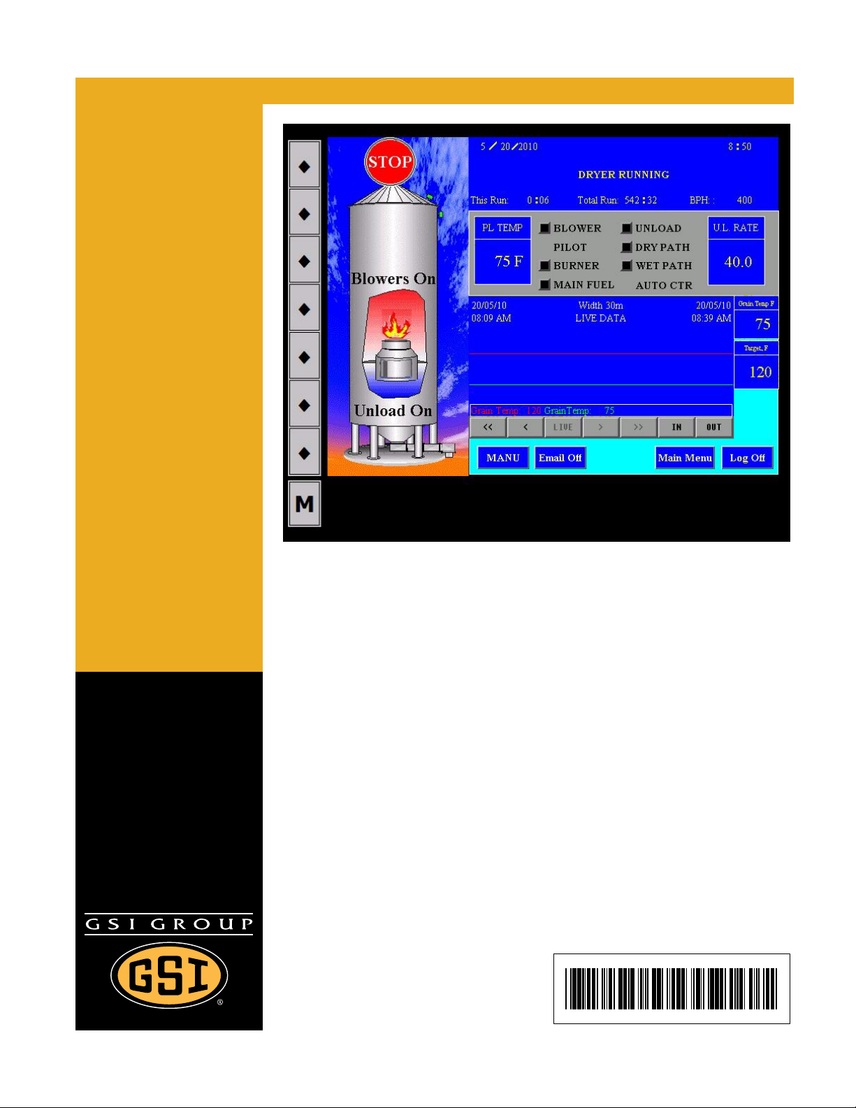
Pressing the “Dryer Display” button will take the user to the screen displayed in Figure 4P which provides
a continuous visual feedback on the current dryer status.
Figure 4P
Viewing Temperature/Moisture History
Press the left and right arrows below the Temperature/Moisture History Chart to move backward and
forward through the graph. Press the “IN” and “OUT” buttons to change the viewing width of the chart.
This width of the chart can show a time span as short as 30 seconds or as long as 48 hours.
On this screen there are several buttons that enable the user to use some remote control options for
the dryer.
Stop Button
Pressing the red “STOP” button will shutdown the dryer.
Auto/Manual Button
Pressing the “Auto/Manual” button allows the operator to change the control of the dryer from automatic
to manual.
Email On/Off Button
Pressing the “Email On/Off” button allows the user to turn the messaging capabilities of the
PLC WatchDog program ON or OFF.
24 PNEG-1755 PLC WatchDog
Page 25

4. PLC WatchDog Operation
Main Menu Button
Pressing the “Main Menu” button will return the user back to the screen that is shown in Figure 4M
on Page 21.
Log Off Button
Pressing the “Log Off” button changes the password status to inactive and will return the user back to the
screen that is shown in Figure 4J on Page 19.
System Variables Button
Password status must be active to enable this function.
Pressing the “System Variables” button will bring up the screen that is shown in Figure 4Q. The “Current
Settings” title is shown on the right half of the screen. This is the current information that the system is
using for setpoints for the individual variables. The information that is listed under the “New Settings” title
is the user entered data from the “View Data - PLC WatchDog” web page.
Figure 4Q
PNEG-1755 PLC WatchDog 25
Page 26

4. PLC WatchDog Operation
If a change is to be made to the current settings of the system, the user should verify the information
displayed under “New Settings” and then proceed to press the “Update System Variables” button. Upon
pressing this button, the updated information will be sent to and stored in PLC. The updated information
will also change on the web page.
Figure 4R
Pressing the “Return to Main Menu” button will return the user back to the screen that is shown in
Figure 4M on Page 21.
Email Settings Button
Password status must be active to enable this function.
Pressing the “Email Settings” button will bring up the screen that is shown in Figure 4S on Page 27. The
“Current Settings” title is shown on the bottom half of the screen. This is the current information that the
system is using for communications to the user. The information that is listed under the “New Settings” title
is the user entered data from the “View Data - PLC WatchDog” web page.
26 PNEG-1755 PLC WatchDog
Page 27

4. PLC WatchDog Operation
Figure 4S
If a change is to be made to the current settings of the system, the user should verify the information
displayed under “New Settings” and then proceed to press the “Update Settings” button. Upon pressing
this button, the updated information will be sent to and stored in PLC WatchDog controller. The updated
information will also change on the web page.
Pressing the “Return to Main Menu” button will return the user back to the screen that is shown in
Figure 4M on Page 21.
Time Settings Button
Password status must be active to enable this function.
Pressing the “Time Settings” button will bring up the screen that is shown in Figure 4T on Page 28. The
“Current Time/Date” title is shown on the right side of the screen. This is the current information that is
stored in the PLC and viewable on the dryer display. The information that is listed under the “New Settings”
title is the user entered data from the “View Data - Set Time Date” web page.
PNEG-1755 PLC WatchDog 27
Page 28

4. PLC WatchDog Operation
Figure 4T
If a change is to be made to the time and date of the system, the user should verify the time/date
information displayed under “New Settings” and then proceed to press the “Update Time Settings” button.
Upon pressing this button, the updated information will be sent to and stored in the PLC. The updated
information will also change on the web page.
Pressing the “Return to Main Menu” button will return the user back to the screen that is shown in
Figure 4M on Page 21.
Log Off Button
Pressing the “Log Off” button changes the password status to inactive. The user must always do this
before closing the web browser. Failure to properly log off may allow additional users access to the
PLC WatchDog application.
SECURITY NOTE: Ultimately, it is the End User’s responsibility to make sure the PLC WatchDog is
properly placed behind a secured network security system.
28 PNEG-1755 PLC WatchDog
Page 29

5. Troubleshooting
Problem Potential Fix
Green LED off on 24 VDC power supply. 1. Check the 120 VAC wiring to the unit. (See Figure 9A on Page 33.)
Red STS LED off on the Red Lion controller. 1. Verify 24 VDC wiring to the unit. (See Figure 9B on Page 34.)
Unable to connect to PLC WatchDog web site.
1. Verify all wiring connections to the Red Lion controller.
2. Verify proper IP address.
PNEG-1755 PLC WatchDog 29
Page 30

6. Technical Support
This section lists the pertinent contact information to be used in the event of a WatchDog system failure.
There are three (3) possible options for help.
Internet Provider
If the WatchDog System is not accessible via the Internet, please make sure the Internet connection being
used is viable. Contact your Internet Provider for assistance.
Dealer
If contacting your Internet Provider has not solved the problem, contact your dea ler for the next steps. The
following items need to be checked by the dealer, in addition to anything they might have already tested:
• Check all connections between WatchDog and even the connections made at your PC, if you
have a Direct Connect system, are good.
GSI Contact Information
If the problem is still unresolved, contact GSI at 217-226-5500
30 PNEG-1755 PLC WatchDog
Page 31

7. Appendix A
Ethernet connector
Antenna connector
Acquiring and Installing a BlueTree Cellular Modem
To acquire a GSI recommended cellular modem, contact the following company:
USAT Corporation
www.usatcorp.com
sales@usatcorp.com
919-942-4214
Ask for a GSI Group account manager.
If you are installing a BlueTree modem acquired from USAT Corporation, there are a few extra installat ion
steps for mounting. Perform the following list of instructions before returning to the “Install Procedure”:
1. Attach the cellular modem to the DIN rail.
2. Connect the cellular modem power terminal “PWR +” to the 24 VDC power supply “+” terminal.
Connect the cellular modem ground terminal “GND” to the 24 VDC power supply “-” terminal.
3. Connect one end of the Ethernet cable to the Ethernet connector on the cellular modem.
Please refer to Figure 7A.
4. Run the antenna wire for the cellular modem through a knockout in the bottom of the power panel
and connect the BNC connector to the modem. The antenna is magnetized and should be placed
with the least obstructions to the nearest tower.
Figure 7A
5. Return to the “Install Procedure” on Page 10.
PNEG-1755 PLC WatchDog 31
Page 32

8. Appendix B
Common List of SMS Carriers and Account Formatting
The following list is not all inclusive. If your carrier is not listed or if you are having problems with receiving
text messages, please contact your local provider for further information.
Alaska Communications Systems number@msg.acsalaska.net
Alltel Wireless (presently merging with Verizon Wireless) number@text.wireless.alltel.com
AT&T Wireless domestic-number@txt.att.net
AT&T grandfathered customers (originally AT&T, then
Cingular, now AT&T Wireless)
AT&T Mobility (formerly Cingular) number@txt.att.net, number@cingularme.com
AT&T Enterprise Paging number@page.att.net
Boost Mobile number@myboostmobile.com
Cellular One (Dobson) number@mobile.celloneusa.com
Cingular (Postpaid) number@cingular.com
Cingular (GoPhone prepaid) number@cingulartext.com
Pioneer Cellular nine-digit-number@zsend.com
Qwest Wireless number@qwestmp.com
Sprint (PCS) number@messaging.sprintpcs.com
Sprint (Nextel) number@page.nextel.com
Straight Talk number@VTEXT.COM
Syringa Wireless number@rinasms.com
number@mmode.com
Unicel number@utext.com
US Cellular number@email.uscc.net
Verizon number@vtext.com
Viaero number@viaerosms.com
Virgin Mobile number@vmobl.com (SMS)
32 PNEG-1755 PLC WatchDog
Page 33

9. Appendix C
Figure 9A
PNEG-1755 PLC WatchDog 33
Page 34

9. Appendix C
Figure 9B
34 PNEG-1755 PLC WatchDog
Page 35

10. Warranty
9101239_1_CR_rev7.DOC (revised July 2009)
GSI Group, LLC Limited Warranty
The GSI Group, LLC (“GSI”) warrants products which it manufactures to be free of defects in materials and workmanship
under normal usage and conditions for a period of 12 months after sale to the original end-user or if a foreign sale,
14 months from arrival at port of discharge, whichever is earlier. The end-user’s sole remedy (and GSI’s only obligation)
is to repair or replace, at GSI’s option and expense, products that in GSI’s judgment, contain a material defect in materials
or workmanship. Expenses incurred by or on behalf of the end-user without prior written authorization from the GSI
Warranty Group shall be the sole responsibility of the end-user.
Warranty Extensions:
The Limited Warranty period is extended for the following products:
Product Warranty Period
Performer Series Direct Drive Fan Motor 3 Years
AP Fans and Flooring
Cumberland
Feeding/Watering
Systems
Grain Systems Grain Bin Structural Design 5 Years
Grain Systems
Farm Fans
Zimmerman
All Fiberglass Housings Lifetime
All Fiberglass Propellers Lifetime
Feeder System Pan Assemblies 5 Years **
Feed Tubes (1-3/4" and 2.00") 10 Years *
Centerless Augers 10 Years *
Watering Nipples 10 Years *
Portable and Tower Dryers 2 Years
Portable and Tower Dryer Frames and
Internal Infrastructure †
5 Years
* Warranty prorated from list price:
0 to 3 years - no cost to end-user
3 to 5 years - end-user pays 25%
5 to 7 years - end-user pays 50%
7 to 10 years - end-user pays 75%
** Warranty prorated from list price:
0 to 3 years - no cost to end-user
3 to 5 years - end-user pays 50%
† Motors, burner components
and moving parts not included.
Portable dryer screens included.
Tower dryer screens not included.
GSI further warrants that the portable and tower dryer frame and basket, excluding all auger and auger drive components,
shall be free from defects in materials for a period of time beginning on the twelfth (12
and continuing until the sixtieth (60
th
) month from the date of purchase (extended warranty period). During the extended
th
) month from the date of purchase
warranty period, GSI will replace the frame or basket components that prove to be defective under normal conditions
of use without charge, excluding the labor, transportation, and/or shipping costs incurred in the performance of this
extended warranty.
Conditions and Limitations:
THERE ARE NO WARRANTIES THAT EXTEND BEYOND THE LIMITED WARRANTY DESCRIPTION SET FORTH
ABOVE. SPECIFICALLY, GSI MAKES NO FURTHER WARRANTY OF ANY KIND, EXPRESS OR IMPLIED,
INCLUDING, WITHOUT LIMITATION, WARRANTIES OF MERCHANTABILITY OR FITNESS FOR A PARTICULAR
PURPOSE OR USE IN CONNECTION WITH: (I) PRODUCT MANUFACTURED OR SOLD BY GSI OR (II) ANY ADVICE,
INSTRUCTION, RECOMMENDATION OR SUGGESTION PROVIDED BY AN AGENT, REPRESENTA TIVE OR
EMPLOYEE OF GSI REGARDING OR RELATED TO THE CONFIGURATION, INSTALLATION, LAYOUT, SUITABILITY
FOR A PARTICULAR PURPOSE, OR DESIGN OF SUCH PRODUCTS.
GSI shall not be liable for any direct, indirect, incidental or consequential damages, including, without limitation, loss of
anticipated profits or benefits. The sole and exclusive remedy is set forth in the Limited Warranty, which shall not exceed
the amount paid for the product purchased. This warranty is not transferable and applies only to the original end-user. GSI
shall have no obligation or responsibility for any representations or warranties made by or on behalf of any dealer, agent
or distributor.
GSI assumes no responsibility for claims resulting from construction defects or unauthorized modifications to products
which it manufactured. Modifications to products not specifically delineated in the manual accompanying the equipment at
initial sale will void the Limited Warranty.
This Limited Warranty shall not extend to products or parts which have been damaged by negligent use, misuse, alteration,
accident or which have been improperly/inadequately maintained. This Limited Warranty extends solely to products
manufactured by GSI.
Prior to installation, the end-user has the responsibility to comply with federal, state and local codes which apply to the
location and installation of products manufactured or sold by GSI.
PNEG-1755 PLC WatchDog 35
Page 36

This equipment shall be installed in accordance with
the current installation codes and applicable
regulations which should be carefully followed in all
cases. Authorities having jurisdiction should be
consulted before installations are made.
Copyright © 2010 by GSI Group
Printed in the USA
GSI Group
1004 E. Illinois St.
Assumption, IL 62510-0020
Phone: 1-217-226-4421
Fax: 1-217-226-4420
www.gsiag.com
 Loading...