

Page 1
PNEG-1745
WatchDog
Installation and Operation Manual
PNEG-1745
Date: 06-07-10
Page 2

2 PNEG-1745 WatchDog
Page 3

Table of Contents
Contents
Chapter 1 Safety ..................................................................................................................................................... 4
Safety Guidelines ...... ... ......................................................................................................................... 4
Dryer Operation ..................................................................................................................................... 5
Emergency Stop Switch .. .... ... ... ... .... ... ... ... ... .... ................................................ ... .... ... ........................... 5
Safety Precautions .... ... ... .... ... ............................................................................................................... 6
Chapter 2 Introduction .......................................................................................................................................... 8
Description ............................................................................................................................................ 8
Features ................................................................................................................................................ 8
Chapter 3 Installation ............................................................................................................................................ 9
Internet Connection ............................................................................................................................... 9
Package Contents ........................................................................................................................... 9
Install Procedure ............................................................................................................................ 11
Network Setup ............................................................................................................................... 15
Default Configuration .......................... ... ... ... .... ... ... ... .............................................................. 15
Configuring the WatchDog Network Settings ......................................................................... 15
Configuring a Modem/Router .......................................... ................................................ ... .... 18
Static IP ........................................................................................................................... 18
DHCP Reservations ........................................................................................................ 18
DHCP Pool ......................................................................................................................18
Accessing the WatchDog .............................................................................................................. 19
Direct Connection ................................................................................................................................ 20
Package Contents ......................................................................................................................... 20
Install Procedure ............................................................................................................................ 22
Installation at the Dryer .......................................................................................................... 22
Installation at the PC .............................................................................................................. 24
Accessing the WatchDog .............................................................................................................. 27
Chapter 4 WatchDog Operation .......................................................................................................................... 28
Login Screen .......... ... ... ... .... ... ... ... ....................................................................................................... 28
Default Operation Screen .................................................................................................................... 29
Table Sample Time Button ............................................................................................................... ... 29
Timer Button ............................................................................................................................ ... ... ... ... 30
Temperature Button ............................................................................................................................ 31
Setup Button ................................................ .... ............................................. ... ... .... ... ... .......... ... ... ... ... 33
Select Time Interval ....................................................................................................................... 33
Metering Roll Speed Setpoint ........................................................................................................ 34
Shutdown Dryer ............................................................................................................................. 34
Manage Accounts .......................................................................................................................... 34
Change Password ......................................................................................................................... 34
Change Site Name ........................................................................................................................ 35
View Button ......................................................................................................................................... 35
M/C (Moisture Setpoint) Button ........................................................................................................... 36
Shutdown Screen ............................................................................................................................. ... 36
Text Version ........................................................................................................................................ 37
Chapter 5 WatchDog Software Update .............................................................................................................. 38
Chapter 6 Troubleshooting ................................................................................................................................. 43
Chapter 7 Technical Support .............................................................................................................................. 44
Chapter 8 Appendix A ......................................................................................................................................... 45
Acquiring and Installing a BlueTree Cellular Modem .......................................................................... 45
Chapter 9 Warranty .............................................................................................................................................. 47
PNEG-1745 WatchDog 3
Page 4
1. Safety
This is the safety alert symbol. It is used to alert you to
potential personal injury hazards. Obey all safety
messages that follow this symbol to avoid possible
injury or death.
WARNING indicates a potentially hazardous situation
which, if not avoided, could result in death or serious injury.
CAUTION indicates a potentially hazardous situation which,
if not avoided, may result in minor or moderate injury.
CAUTION used without the safety alert symbol indicates a
potentially hazardous situation which, if not avoided, may
result in property damage.
NOTE indicates information about the equipment that you
should pay special attention.
DANGER indicates an imminently hazardous situation
which, if not avoided, will result in death or serious injury.
Personnel operating or working around electric fans should read this manual. This manual
must be delivered with the equipment to its owner. Failure to read this manual and its
safety instructions is a misuse of the equipment.
WARNING! BE ALERT!
Safety Guidelines
This manual contains information that is important for you, the owner/operator, to know and understand.
This information relates to protecting personal safety and preventing equipment problems. It is the
responsibility of the owner/operator to inform anyone operating or working in the area of this equipment of
these safety guidelines. To help you recognize this information, we use the symbols that are defined
below. Please read the manual and pay attention to these sections. Failure to read this manual and its
safety instructions is a misuse of the equipment and may lead to serious injury or death.
4 PNEG-1745 WatchDog
Page 5
1. Safety
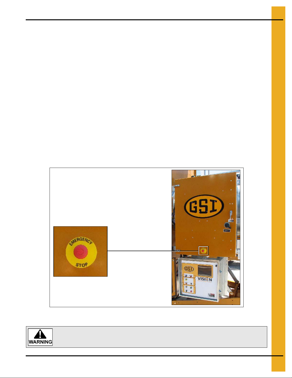
Pushing the Emergency Stop switch does not interrupt the main power to the
upper control box panel.
Dryer Operation
Thank you for choosing a GSI product. It is designed to give excellent performance and service for
many years.
This manual describes the operation and service for all standard production model dryers. T hese models
are available for liquid propane or natural gas fuel supply, with either 1 phase 230 volt, or 3 phase
230 or 440 volt electrical power.
Our foremost concern is your safety and the safety of others associated with this equipment. We want to
keep you as a customer. This manual is to help you understand safe operating procedures and some
problems which may be encountered by the operator and other personnel.
As owner and/or operator, it is your responsibility to know what requirements, hazards and precautions
exist, and to inform all personnel associated with the equipment or in the area. Safety precautions may be
required from the personnel. Avoid any alterations to the equipment. Such alterations may produce a very
dangerous situation where SERIOUS INJURY or DEATH may occur.
This equipment shall be installed in accordance with the current installation codes and applicable
regulations which should be carefully followed in all cases. Authorities having jurisdiction should be
consulted before installations are made.
Emergency Stop Switch
The Emergency Stop switch is located on the upper control box door. Pushing the Emergency
Stop switch will interrupt the control power and stop all dryer functions.
PNEG-1745 WatchDog 5
Page 6

1. Safety
Safety Precautions
READ THESE INSTRUCTIONS BEFORE INSTALLATION AND OPERATION
SAVE FOR FUTURE REFERENCE
1. Read and understand the operating manual before attempting to operate the dryer.
2. NEVER operate the dryer while the guards are removed.
3. Power supply should be OFF for service of electrical components. Use CAUTION in checking voltage
or other procedures requiring the power to be ON.
4. Check for gas leaks at all gas pipe connections. If any leaks are detected,
Shutdown and repair before further operation.
5. NEVER attempt to operate the dryer by jumping or otherwise bypassing any safety devices on
the unit.
6. Set pressure regulator to avoid excessive gas pressure being applied to the burner during ignition
and when the burner is in operation. DO NOT exceed maximum recommended drying temperature.
7. Keep the dryer clean. DO NOT allow fine material to accumulate in the plenum chamber.
Clean grain is easier to dry. Fine material increases resistance to airflow and requires removal
of extra moisture.
8. Keep auger drive belts tight enough to prevent slippage.
9. Use CAUTION in working around high speed fans, gas burners, augers and auxiliary conveyors
which can START AUTOMATICALLY.
10. Keep area around air inlet to the fan clear of any obstacles and combustible materials.
11. BEFORE attempting to remove and reinstall any propeller, make sure to read the
recommended procedure.
12. Make sure that capacities of auxiliary conveyors are matched to dryer auger capacities.
13. DO NOT operate in an area where combustible material will be drawn into the fan.
DO NOT
operate dryer.
14. The operating and safety recommendations in this manual pertain to the common cereal
grains as indicated. When drying any other grain or products, consult the factory for
additional recommendations.
15. Routinely check for any developing gas plumbing leaks. Check LP vaporizer for contact with
burner vanes.
6 PNEG-1745 WatchDog
Page 7

1. Safety
Use Caution in the Operation of this Equipment
This dryer is designed and manufactured with operator safety in mind. However, the very nature of a
grain dryer having a gas burner, high voltage electrical equipment and high speed rotating parts, presents
hazards to personnel which cannot be completely safeguarded against without interfering with the efficient
operation of the dryer and reasonable access to its components.
Use extreme caution in working around high speed fans, gas-fired heaters, augers and auxiliary conveyors,
which may start without warning when the dryer is operating on automatic control.
Continued safe, dependable operation of automatic equipment depends, to a great degree, upon the
owner. For a safe and dependable drying system, follow the recommendations within the Owner’s Manual
and make it a practice to regularly inspect the unit for any developing problems or unsafe conditions.
Take special note of the Safety Precautions on Page 6 before attempting to operate the dryer.
PNEG-1745 WatchDog 7
Page 8

2. Introduction
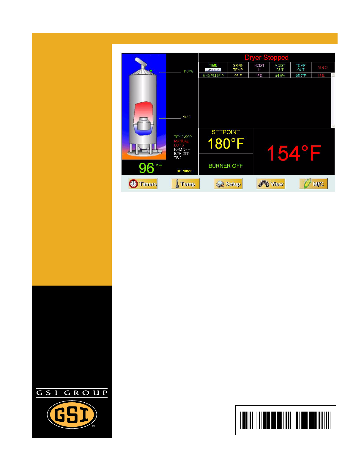
Description
The WatchDog System allows for remote monitoring of a Vision dryer. There are two (2) configurations
available: Internet Connection and Direct Connection.
Internet Connection allows the user to view the dryer from any device that has a web browser. Internet
Explorer and Mozilla Firefox were the only two (2) browsers tested, but other browsers should be able to
view it without problem. Some phones are available that view the graphics correctly; other phones will
have to view the text version.
Direct Connection allows one computer to view the dryer status. A hardwire from the dryer is connected
to the WatchDog enclosure residing at the computer. The cable should run no longer than a distance of
1000' and CAT5 is recommended.
Features
1. Remote monitoring of dryer.
2. Remote shutdown of dryer.
3. Remote drying parameter adjustment. (Plenum and grain temperature setpoints, timer setpoints, etc.)
4. Web browser is the only software needed by the customer.
5. Text message and/or e-mail can be sent to alert customers of shutdowns. (Not available on Direct
Connection type.)
6. Can be updated via SD card.
8 PNEG-1745 WatchDog
Page 9
3. Installation
4
5
6
1
2
Internet Connection (Part #: VIS-WATCH-IC)
This option requires an active internet connection be present at the dryer via Ethernet (RJ-45 connection).
It is recommended that either an Internet Service Provider (ISP) technician or someone versed in
networking be present during installation.
GSI is not responsible for the required connection.
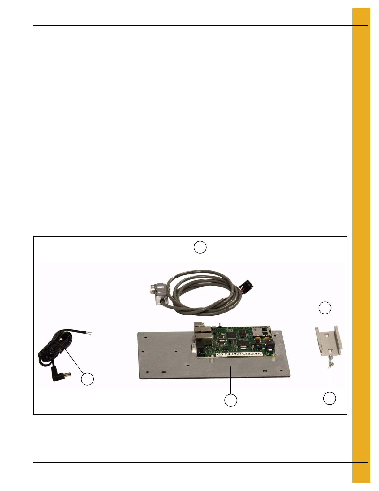
Package Contents
The contents of this package are pictured in Figure 3A. Please refer to Figure 3A during installation.
Package contains:
1. Mounting plate with WatchDog circuit board attached.
2. WatchDog power cable.
3. Two (2) 1/4" mounting nuts. (Not Shown)
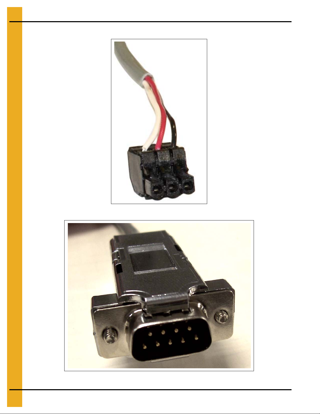
4. DB9 to 3 position quick connect cable (Serial Cable #1).
5. 3" DIN rail.
While GSI’s Technical Support group can offer suggestions,
6. Two (2) self-tapping 1/4" screws.
7. Ten (10) cable ties for routing wires. (Not Shown)
8. Four (4) cable tie anchors for routing wires. (Not Shown)
Figure 3A
PNEG-1745 WatchDog 9
Page 10
3. Installation
Serial cable connector figures: (See Figure 3B and Figure 3C.)
Figure 3B 3 Position Quick Connect
Figure 3C DB9 Connector
10 PNEG-1745 WatchDog
Page 11
3. Installation
Mounting plate with
WatchDog circuit board
Install Procedure
This installation takes place in the lower control panel of the Vision system. Follow the steps listed below
to install the components:
1. Turn OFF power to dryer and control panel.
2. If a cellular modem is being installed, first refer to Appendix A on Page 45 for a few extra instructions
and then return here.
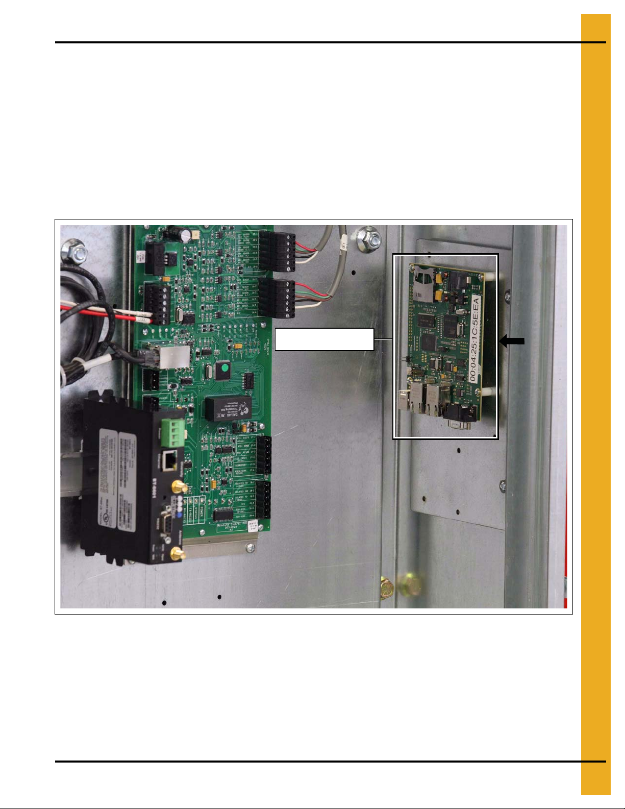
3. Place mounting plate with WatchDog circuit board attached over two (2) existing bolts on the right
side of the lower control panel. Secure it using the two (2) 1/4" nu ts supplied. Position the mount ing
plate so the white sticker is in clear view. (See Figure 3D.)
PNEG-1745 WatchDog 11
Figure 3D
Page 12
3. Installation
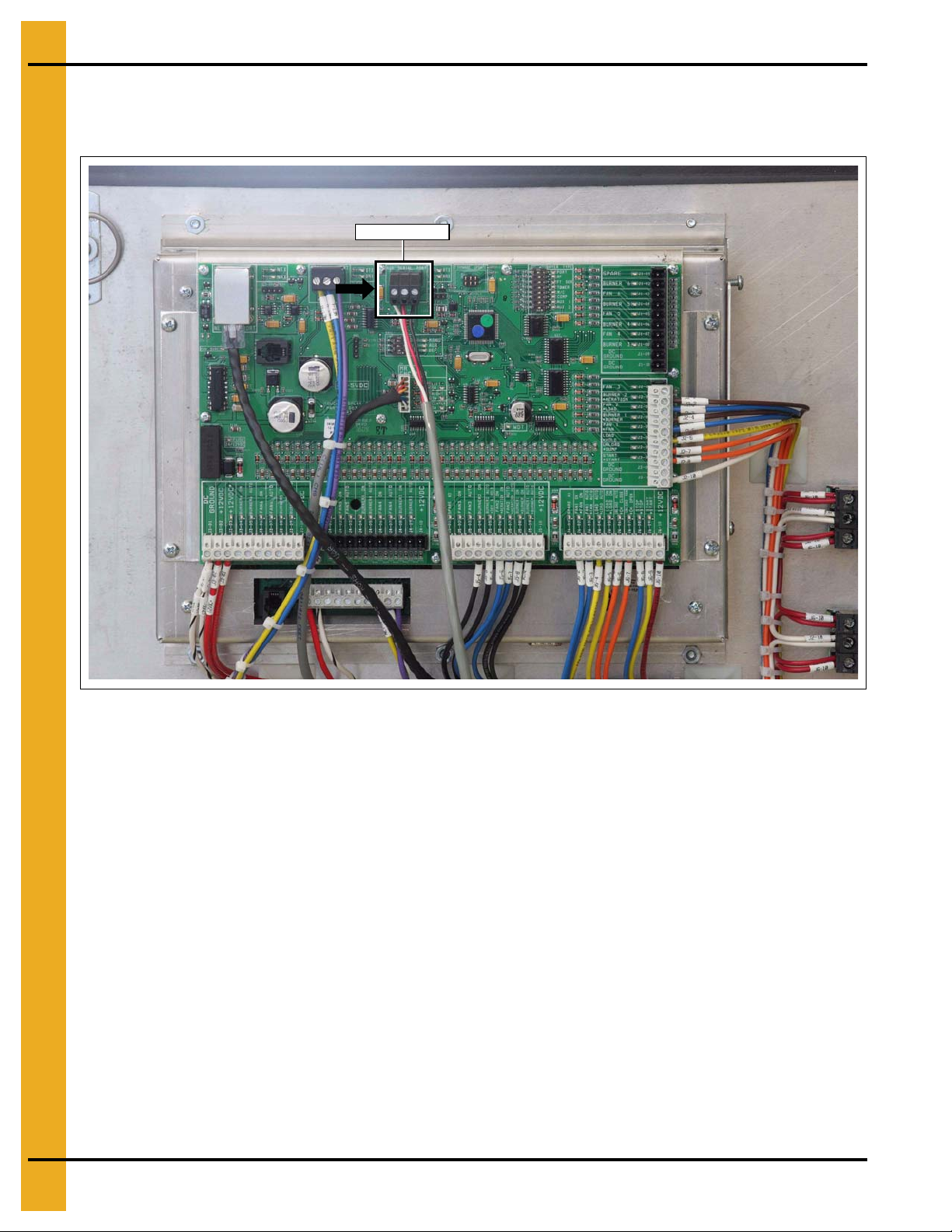
Aux serial port
4. Connect the 3 position quick connector of Serial Cable #1 to the “AUX SERIAL PORT” on the
Display I/O board located on the back of the touch screen. The connector is polarized so care should
be taken to plug it in correctly. (See Figure 3E.)
Figure 3E
12 PNEG-1745 WatchDog
Page 13
3. Installation
DB9 Connector
5. Plug the DB9 connector of Serial Cable #1 into the DB9 connector on the WatchDog circuit board.
Tighten the two (2) screws to secure the connection. (See Figure 3F.)
Figure 3F
6. If a cellular modem is being used, the bare leads of the WatchDog power cable should be connected
to the cellular modem power terminals as follows:
Black with faint white line lead - PWR +
Black lead with faint white writing lead - PWR GND
Figure 3G
NOTE: These are the same slots holding the wires coming from the moisture control panel.
PNEG-1745 WatchDog 13
Page 14
3. Installation
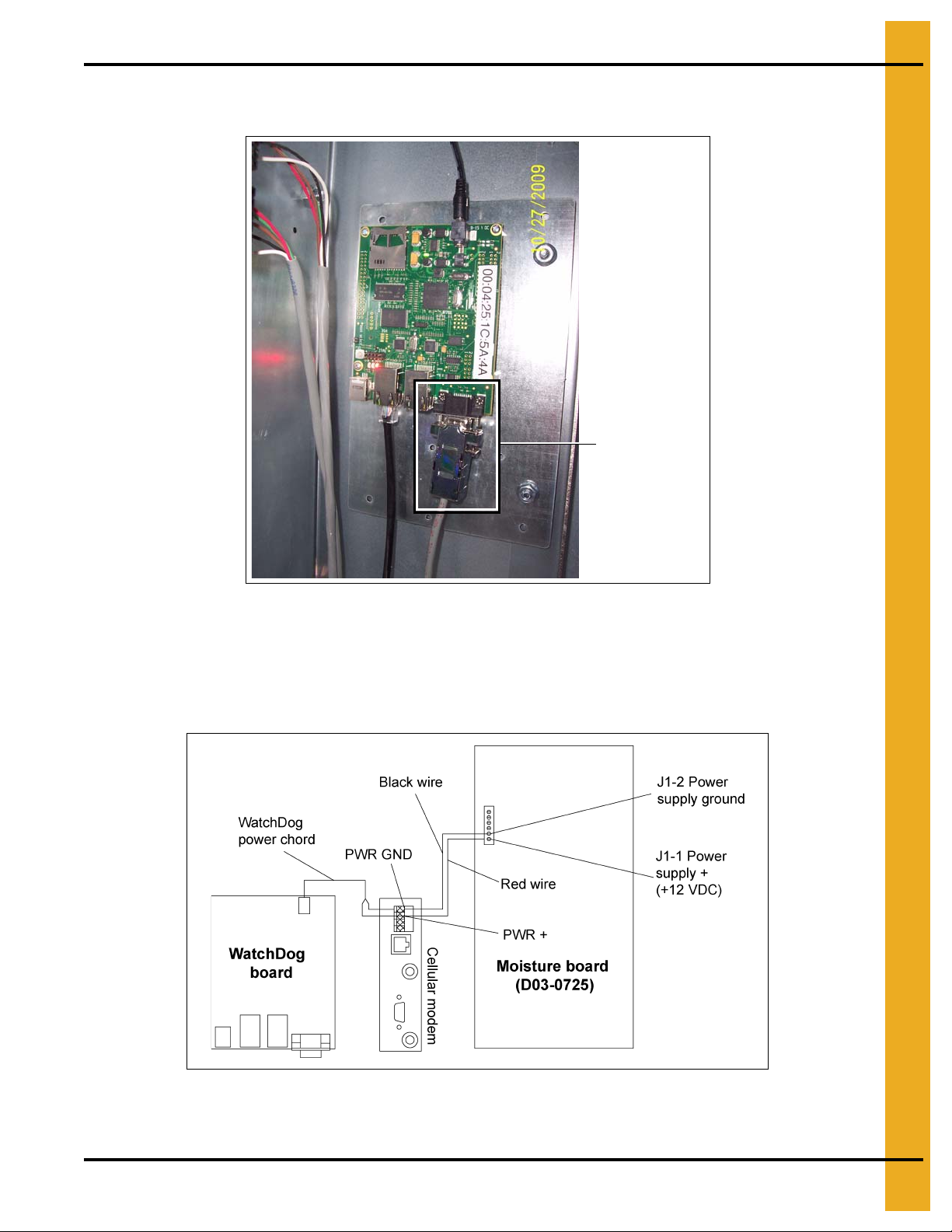
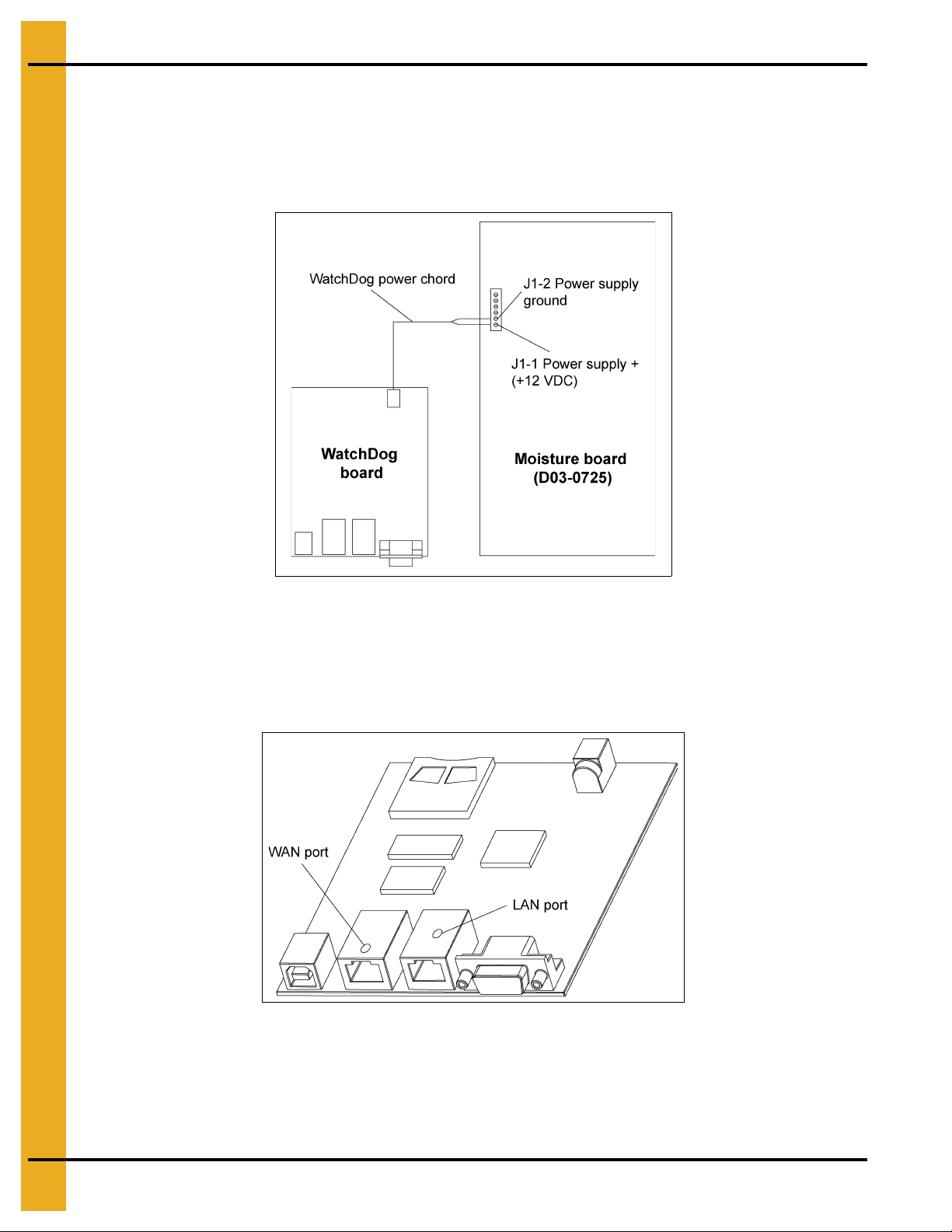
If a cellular modem is NOT being used, the bare leads of the WatchDog power cable should be
connected to the moisture control board as follows:
Black with faint white line lead - J1-1 “POWER SUPPLY+ (+12 VDC)”
Black lead with faint white writing lead - J1-2 “POWER SUPPLY GROUND”
Please refer to Figure 3H.
Figure 3H
7. The barrel connector of the WatchDog power cable should be plugged into the power connector on
the WatchDog circuit board. (See Figure 3H.)
8. Plug the Ethernet cable with a live internet connection into the WAN port on the WatchDog circuit
board. The WAN port is to the left, farthest from the cabinet door. (See Figure 3I.)
Figure 3I
NOTE: Use cable ties and anchors to secure wires.
9. Turn ON power to the dryer and control panel. A green LED should illuminate on the WatchDog
circuit board indicating power. A red LED will illuminate when the WatchDog has finished booting
and is ready to monitor.
14 PNEG-1745 WatchDog
Page 15
3. Installation
Network Setup
This section is intended to help ISP or network technicians install th e WatchDog. If this section does not
make sense to you, it is strongly advised to request the service of a network technician.
Default Configuration
The WatchDog’s Wide Area Network (WAN) port default is setup as a Dynamic Host Configuration
Protocol (DHCP) client. The script to configure the port is only executed on start-up. To pull down an
Internet Protocol (IP) address, it needs to be attached to a DHCP server when it is booted.
The Media Access Control (MAC) address is printed on a label that is attached to the front of the
WatchDog board.
Configuring the WatchDog Network Settings
To access the WatchDog setup, connect a computer to the LAN (Local Area Network) port of the board,
using a CAT5 network cable. Refer to Figure 3I on Page 14 for LAN port location. Make sure the red “SYS”
LED is illuminated on the board, as this ensures the Operating System (OS) has booted completely.
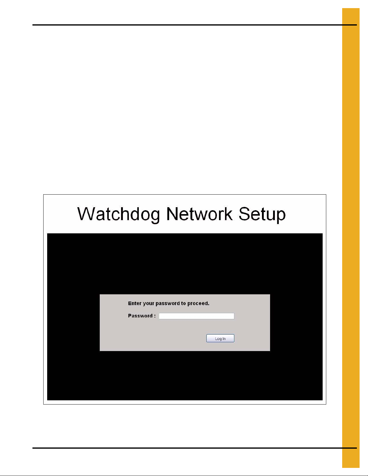
Open a web browser (i.e. Internet Explorer, Mozilla Firefox …) and type “http://10.0.0.1/setup” into the
URL bar. (Where you would normally type www.google.com for example.) This will bring up a Login screen
as shown in Figure 3J.
Figure 3J
PNEG-1745 WatchDog 15
Page 16

3. Installation
The default password is default. The password is the same as is used to access the WatchDog.
Therefore, if the user has changed the password, the setup password will be whatever they have ch anged
it to. If the user forgets his/her password, see the user manual for resetting the password.
Once logged in, Figure 3K should be displayed on the screen.
Figure 3K
The current setup is displayed to the left of this screen. The address will differ from Figure 3K. If the device
is setup as a DHCP Client and the IP address that is displayed is “10.11.12.1”, this means the DHCP
Server did not serve the board an IP address. If you were expecting the board to pull down a n IP address,
reset the power on the modem/router and then the WatchDog board. If these addresses need to be
modified, click the “Configure” button to the right. This will take you to Figure 3L.
Figure 3L
16 PNEG-1745 WatchDog
Page 17

3. Installation
At first, neither DHCP or Static is selected. Choose one or the other depending on how you would like to
setup the WatchDog’s network parameters. If “Static IP” is selected, the following fields are displayed for
entry: IP Address, Subnet Mask, Default Gateway, DNS 1 and DNS 2. Figure 3M depicts these entries.
Figure 3M
Note that all fields are required when using the Static IP option. If you are missing any of the addresses,
contact your service provider and they will be able to give you the missing information.
Once you have chosen the setup that you would like, click “Apply Settings”. After clicking the button you
will be redirected to a page that counts down from 90 seconds. This is changing the board’s configuration
and resetting it so the changes will take effect. The network scripts only execute on boot, so the WAN port
on the board needs to be connected to the modem/router on boot.
After the timer expires, you will be redirected back to the Network Status page. (See Figure 3K on
Page 16.) If the page does not display the addresses correctly, make sure the red LED on the WatchDog
board is ON and then refresh the web page.
PNEG-1745 WatchDog 17
Page 18

3. Installation
Configuring a Modem/Router
If the WatchDog board is connected to a modem/router that is configurable, listed below are a few
recommendations to assist with setup. The methods below do not cover every configuration that is
available. If the modem is not configurable, refer to Page 17 for setting the WatchDog network to the static
IP allocated by the service provider.
Static IP
This is the preferred method for installation. Acquire the LAN’s default gateway address of the
modem/router. Replace the last number of the default gateway with a number that is not within the DHCP
pool range. For example, if the default gateway is 192.168.2.1 and the modem/router’s DHCP pool range
is 100 to 200, replace the last number of the default gateway address with, say, 50. This would result in
an address of 192.168.2.50. Using the WatchDog network Setup screens, set the static IP address of the
board to the chosen IP address, refer to Page 17.
In the router/modem configuration, forward incoming request on ports 22, 23 and 80 to the static IP.
DHCP Reservations
A reservation can be an option in the configuration of a modem/router. It can be set to serve a given
MAC address with a certain IP address when it is introduced to the network. As mentioned above, the
MAC address of the WatchDog board can be found on a label on the front of it.
Once the IP address has been setup for the MAC address, forward incoming request on ports 22, 23 and
80 to the board.
DHCP Pool
If the modem/router does not have DHCP reservations, the board can be allowed to pull an IP address
from the DHCP server’s IP range. This method is only recommended when the WatchDog is the only node
on the network.
Reduce the IP range of the DHCP server down to one IP address. This will be the only IP address that the
DHCP server is allowed to serve to the network. Once the range has been narrowed to one, forward
incoming request on ports 22, 23 and 80 to the single IP address.
18 PNEG-1745 WatchDog
Page 19

3. Installation
Accessing the WatchDog
The WatchDog is accessed from any PC that has an internet connection and web browser. Some phones
are available that view the graphics correctly; other phones will have to view the text version.
1. Make sure that the dryer is powered up and the Vision application is running.
2. On the PC or phone, open up a web browser, i.e. Internet Explorer, Mozilla Firefox, etc.
3. In the URL bar, enter the static IP address given by the ISP. There is no need to put “www”, simply
enter the number sequence. The IP address shown in the Figure 3K on Page 16 is just for illustration
purposes. The IP address you enter will be different.
4. The “Login Screen” should now appear. If it does not, run back through the install procedure to verify
everything is connected properly.
Figure 3N
5. Once the “Login Screen” appears, move on to Chapter 4 “WatchDog Operation” on Page 28.
PNEG-1745 WatchDog 19
Page 20

3. Installation
4
2
2
3
1
Direct Connection (Part #: VIS-WATCH-IC)
This option allows the user to connect their dryer directly to one Personal Computer (PC) using two (2)
short-haul modems and four (4) wires, CAT5 is recommended. Text messaging and e-mail is not
available with this option.
Package Contents
The contents of this package are pictured in Figure 3O. Please refer to Figure 3O during installation.
Package contains:
1. WatchDog enclosure (white case).
2. Two (2) short-haul modems w/ power supplies.
3. DB25 to 3 position quick connect cable (Serial Cable #2).
4. DB25 to DB9 serial cable (Serial Cable #3).
5. Ten (10) cable ties for routing wires. (Not Shown)
6. Four (4) cable tie anchors for routing wires. (Not Shown)
Figure 3O
20 PNEG-1745 WatchDog
Page 21

Serial cable connector figures: (See Figures 3P, 3Q and 3R.)
3. Installation
Figure 3P 3 Position Quick Connect
Figure 3Q DB9 Connector
PNEG-1745 WatchDog 21
Figure 3R DB25 Connector
Page 22

3. Installation
Aux serial port
Install Procedure
This installation is split into two (2) steps. Some installation is done in the lower control panel of the Vision
system at the dryer and the rest at the PC location. This manual does not cover running the wires between
the two (2) locations, as this is the customer’s responsibility. CAT5 cable is recommended by GSI.
Installation at the Dryer
The following items will be installed at the dryer location:
1. One short-haul modem w/ power supply.
2. DB25 to 3 position quick connect cable (Serial Cable #2).
3. Use cable ties and anchors when necessary.
Follow the steps listed below to install all components required at the dryer:
1. Turn OFF power to dryer and control panel.
2. Connect the 3 position quick connector of Serial Cable #2 to the “AUX SERIAL PORT” on the
Display I/O board located on the back of the touch screen. The connector is polarized so care should
be taken to plug it in correctly. (See Figure 3S.)
Figure 3S
22 PNEG-1745 WatchDog
Page 23

3. Installation
3. Plug the DB25 connector of Serial Cable #2 to one of the short-haul modems. Care should be taken
to make sure the switches on the short-haul modem match those in Figure 3U.
DCE
Figure 3T
Dryer side
switch positions
SIM
T-ON/R-ON
4321
Figure 3U
PNEG-1745 WatchDog 23
Page 24

3. Installation
4. Now, the four (4) wires that run from the dryer to the PC location need to be connected to the
short-haul modem. Use the following table to document what color is attached to which terminal.
This will help in connecting the other end of the cable at the PC location.
Table 1: Wire Colors at Dryer
Terminal # at Dryer Wire Color
1
2
3
4
NOTE: The order of the colors in the picture are for illustrative purposes only.
5. The short-haul modem power supply should be plugged into a 120 VAC receptacle (not provided)
and the barrel connector into the short-haul modem. The red power light should come ON.
6. Turn ON power to dryer and control panel.
NOTE: Clean-up and arrange the wires using the provided cable ties and anchors.
Installation at the PC
The following items will be installed at the PC location:
1. WatchDog enclosure (white case).
2. One short-haul modem w/ power supply.
3. DB25 to DB9 serial cable (Serial Cable #3).
4. 3' Ethernet Cable.
5. Use cable ties and anchors when necessary.
Follow the steps listed below to install all components required at the PC location:
1. Fill in Table 2 below with the wire colors in the same order as Table 1 above from 1-4.
Table 2: Wire Colors at Dryer and PC
Terminal # at Dryer Wire Color Terminal # at PC
1 3
24
3 1
42
24 PNEG-1745 WatchDog
Page 25

SIM
3. Installation
DCE
T-ON/R-ON
4321
PC Side
DTE
4321
T-ON/R-ON
SIM
Dryer side
Figure 3V
Connect the wires to the short-haul modem according the terminal numbers listed at the right of
Table 2 on Page 24.
2. Plug the DB25 connector of Serial Cable #3 to the short-haul modem. Care should be taken to make
sure the switches on the short-haul modem match those in Figure 3X on Page 26.
Figure 3W
PNEG-1745 WatchDog 25
Page 26

3. Installation
PC side
switch positions
SIM
DTE
T-ON/R-ON
4321
DB9 Connector
RJ-45 Connector
Figure 3X
3. Attach the DB9 connector of Serial Cable #3 to the DB9 connector on the WatchDog enclosure.
Figure 3Y
4. Plug an Ethernet cable into the RJ-45 connector on the WatchDog enclosure. Please refer
to Figure 3Y.
5. Attach the other end of the Ethernet cable to the Ethernet port on the PC.
26 PNEG-1745 WatchDog
Page 27

3. Installation
6. The short-haul modem power supply should be plugged into a 120 VAC receptacle and the barrel
connector into the short-haul modem. The red power light should come ON.
7. Plug the power cable from the WatchDog enclosure into a 120 VAC receptacle.
Accessing the WatchDog
The WatchDog is accessed from the PC that the WatchDog enclosure is atta ched to. This PC will be used
in the section to connect to the dryer.
1. Make sure that the dryer is powered up and the Vision application is running. Also, verify the
WatchDog enclosure and both short-haul modems are plugged in.
2. On the PC, open up a web browser, i.e. Internet Explorer, Mozilla Firefox.
3. In the URL bar, enter “10.0.0.1” without the double quotes. There is no need put “www”, simply enter
the number sequence.
4. The “Login Screen” should now appear. If it does not, run back through the install procedure to verify
everything is connected properly.
Figure 3Z
5. Once the “Login Screen” appears, move on to Chapter 4 “WatchDog Operation” on Page 28.
PNEG-1745 WatchDog 27
Page 28

4. WatchDog Operation
Login Screen
When the web browser initially makes contact with the WatchDog System, you will be presented with a
screen requesting a password. (See Figure 4A.) Once the password has been entered, you must press
the LOG IN button to accept the password. Default password is default.
Figure 4A
If you have forgotten the password, press the “Forgot Password” button shown in Figure 4A. This will bring
up the screen shown in Figure 4B. This screen will ask for the WatchDog board’s “MAC Address”. This
sequence of numbers and letters (all capitals) can be found on a sticker located on the top of the
WatchDog board.
Figure 4B
Once the password has been reset, you may log in with the default password, which is simply default
(all lower case), but immediately go to the setup menu an d change the de fault pa ssword to someth ing of
your choice. Please record and place the new password information in a safe place.
28 PNEG-1745 WatchDog
Page 29

4. WatchDog Operation
Default Operation Screen
The screen in Figure 4C will be displayed, unless the dryer is shutdown, upon connection to the dryer if it
is a tower dryer. This very closely resembles how the screen would appear at the dryer. All the buttons
function exactly as they would if pressed on the dryer screen, except for the Setup and View buttons.
These buttons on this screen allow changes to be made to the setup of the WatchDog System and to view
information related to the WatchDog System. The menus/information below each button will be described
more fully in the following sections.
Figure 4C
All information displayed around the dryer picture, is exactly as it would appear on the d ryer scr een. The
lower right 1/4 of the screen shows the state of each burner, once again, as it would be displayed at the
dryer. The log of temperatures and moistures on the right hand side of the screen functions exactly as it
does at the dryer, but the data displayed may be different. (It is not downloaded from the dryer.) Finally,
the status bar displayed in the upper right hand corner gives the current status of the dryer and shows the
same information that is presented at the dryer.
Table Sample Time Button
Pressing the button in the upper left hand of the table view will bring up the screen shown in
Figure 4C. This sets the number of minutes for each sample that is entered into the data log table.
NOTE: If the sample time (See Figure 4D on Page 30) for the WatchDog System is set longer than the
history time interval, the table will miss samples.
PNEG-1745 WatchDog 29
Page 30

4. WatchDog Operation
Figure 4D
Timer Button
Pressing the button will display a screen similar to that in Figure 4E. The actual layout will vary
depending on the type of dryer and its particular setup. Pressing any of these timer buttons will allow
modification of that timer’s setpoint value.
Figure 4E
30 PNEG-1745 WatchDog
Page 31

4. WatchDog Operation
For example, pressing the button will bring up the timer minutes modification dialog box
shown in Figure 4F. Enter the number of minutes and press OK.
Figure 4F
Another dialog box will then appear prompting the second’s setpoint to be entered as shown in Figure 4G.
Figure 4G
Depending on the security settings of the particular browser you may have to temporally allow
scripted windows. Using Internet Explorer, simply right click and select OK and press Timer button again .
All other timer setpoints are set similarly.
Temperature Button
Pressing the button will bring up a screen very similar to that shown in Figure 4H on Page 32.
It may vary slightly depending on the dryer’s setup. The current setpoint of each plenum an d grain column
temperature is shown to the right of each setpoint button.
PNEG-1745 WatchDog 31
Page 32

4. WatchDog Operation
Figure 4H
Pressing the button will bring up a dialog requesting a new setpoint value to be entered.
(See Figure 4H.) Once the new value has been entered, press the OK button to accept or CANCEL to
keep the old value. All other temperature setpoints are set similarly. (See Figure 4I.)
Figure 4I
32 PNEG-1745 WatchDog
Page 33

4. WatchDog Operation
Setup Button
Pressing the button will bring up the screen shown in Figure 4J. The Setup screen is not used
to setup the dryer as it would at the dryer control, but it is used to further setup the WatchDog System.
The Setup screen has been broken into six (6) distinct functions and these will be addressed in the
following sections.
Figure 4J
Select Time Interval
This set of radio buttons allows the user to select how often the WatchDog System contacts the dryer for
information. For example, if 20 Seconds is chosen, as shown in Figure 4K, the WatchDog screen will be
updated once every 20 seconds. If you have limited Internet bandwidth, it is best to choose the longest
interval that is acceptable.
Figure 4K
PNEG-1745 WatchDog 33
Page 34

4. WatchDog Operation
Metering Roll Speed Setpoint
This portion of the Setup screen allows the user to adjust the metering roll speed setpoints. Only the
setpoints required by the current setup are shown, so the screen may vary from the one shown in
Figure 4L. Do not enter a percent (%) symbol, e.g. to enter 50% simply enter 50 and press OK.
Figure 4L
Shutdown Dryer
Pressing the stop sign displayed on the Setup screen will shutdown the dryer. Yo u will be asked if th is is
correct via a small dialog box before the dryer will be shutdown. (See Figure 4M.)
Figure 4M
Manage Accounts
This section of the Setup screen is used to add or delete e-mail and text messaging accounts to be notified
when the dryer experiences a shutdown. Clicking “Edit Accounts” will open a new window, allowing entry
of e-mail account or text message information. Please use the help (shown after pressing the Edit
Accounts button) button for more information. (See Figure 4N.)
Figure 4N
Change Password
Click the “Change Password”, under the setup menu (See Figure 4O), to change the current password.
If you have used the method described on Page 28 to reset the password to the default value,
please change the password, for security reasons, immediately. Follow the instructions for changing
the password.
Figure 4O
34 PNEG-1745 WatchDog
Page 35

4. WatchDog Operation
Change Site Name
The site name is displayed at the top of the webpage. This is a way to personalize the WatchDog remote
monitoring system. It is especially useful when viewing more than one WatchDog on a single PC. This will
identify which site the user is currently looking at. The site name is also included in the text messages and
e-mails that are sent due to dryer shutdowns. (See Figure 4P.)
Figure 4P
View Button
Pressing the will bring up a screen giving information about the WatchDog System. The
version number is currently displayed with other information being added as needed. (See Figure 4Q.)
Figure 4Q
PNEG-1745 WatchDog 35
Page 36

4. WatchDog Operation
M/C (Moisture Setpoint) Button
Pressing the button will bring up a dialog box requesting to modify the current grain temperature
setpoint or the moisture setpoint depending upon the setup of the dryer. For example, Figure 4R shows
the dialog box that is presented when using temperature to control the moisture output of the dryer.
Figure 4R
Shutdown Screen
If the drying equipment experiences a shutdown, the screen in
System and an audio file will be played (dogs ba rk ing). It in dicates that the drye r h as sh utdown and gives
the reason why.
The shutdown can only be cleared by pressing the STOP button at the dryer.
Figure 4S
will be displayed by the WatchDog
Figure 4S
36 PNEG-1745 WatchDog
Page 37

4. WatchDog Operation
Text Version
The text version of WatchDog leaves all of the fancy graphics behind and simply displays a few key
parameters denoting the status of the dryer. This version was put in place to allow phones that cannot
handle the graphics the ability to monitor the dryer. Shutdowns will still be displayed when using the
text version. (See Figure 4T.)
To access, scroll to the bottom of the webpage and click on the “Click Here for the Text Version” link. There
is not a password associated with this version, but no parameters can be changed from the text version.
It is strictly a monitoring system.
Figure 4T
PNEG-1745 WatchDog 37
Page 38

5. WatchDog Software Update
Process
This process assumes the user is using Windows XP.
1. Make an SD card readable by your computer. This may require a special piece of equipment from a
consumer electronics store. Below is an example of an SD card. (See Figure 5A.)
Figure 5A
2. Download the “WatchDog Update Version 1.03 installation program” file from http://www.gsiag.com/
gsi/progs/watchdog/to a directory on your computer.
3. Execute the “WatchDog Update v103.exe” from whatever directory you downloaded it to.
4. Read the License Agreement. If you agree to the terms, select the “I agree to the terms of this license
agreement” and click the “Next” button. (See Figure 5B.)
Figure 5B
38 PNEG-1745 WatchDog
Page 39

5. Click the “Next” button to proceed. (See Figure 5C.)
5. WatchDog Software Update
Figure 5C
6. This will bring you to a list of changes made from the previous version. Click “Next” to proceed.
(See Figure 5D.)
Figure 5D
PNEG-1745 WatchDog 39
Page 40

5. WatchDog Software Update
7. Select the drive that your SD card is using and click “Next”. (See Figure 5E.)
Figure 5E
8. Verify the correct drive has been selected and click “Next”. (See Figure 5F.)
Figure 5F
40 PNEG-1745 WatchDog
Page 41

5. WatchDog Software Update
9. The installer is now ready to install the update to the SD card. Click “Next” to install. (See Figure 5G.)
Figure 5G
10. Once the files have been transferred, the SD card installation is complete. Click “Finish” to exit
the installer. (See Figure 5H.)
Figure 5H
PNEG-1745 WatchDog 41
Page 42

5. WatchDog Software Update
11. After turning the WatchDog power OFF, insert the SD Card into the WatchDog board as
shown in Figure 5I.
Figure 5I
12. Once the SD Card is securely placed in the reader, return power to the WatchDog board and allow
3 minutes to pass.
13. After 3 minutes have passed, turn the WatchDog power OFF and then remove the SD Card from
the board.
14. Return power to the WatchDog board and wait for the red “SYS” light to come ON. The WatchDog is
now updated.
42 PNEG-1745 WatchDog
Page 43

Internet Connection Problems
Problem Potential Fix
“Check connection between WatchDog and Dryer.
Also check Vision Version. Should be 1.00 or newer.”
is being displayed.
6. Troubleshooting
1. Check the current version of Vision. It should be 1.00 or newer.
2. Make sure the Vision is powered ON and the dryer application
is running.
3. Check the connection points of the Serial Cable #1 between
the WatchDog circuit board and Display I/O circuit board.
4. If this happens on initial install, check that the cable is wired to
the 3 position connector correctly. Below is the correct wiring.
Use on ohm meter to check continuity.
1. Check the Ethernet connection to the WatchDog circuit board.
“Internet connection to the dryer has been lost” is
being displayed.
Login Password does not work. Refer to “Forgot Password Screen” Figure 4A on Page 28.
2. Verify the internet connection is working by removing the
Ethernet cable from the WatchDog circuit board and plugging
it into a PC. On the PC, open a web browser and try to access
a website of the choice. If this fails, contact the ISP.
Direct Connection Problems
Problem Potential Fix
1. Check the current version of Vision. It should be 1.00 or newer.
2. Make sure the Vision is powered ON and the dryer application
is running.
3. Check the connection points of the Serial Cable #2 between
the WatchDog circuit board and Display I/O circuit board.
4. If this happens on initial install, check that the cable is wired to
“Check connection between WatchDog and Dryer.
Also check Vision Version. Should be 1.00 or newer.”
is being displayed.
the 3 position connector correctly. Below is the correct wiring.
Use on ohm meter to check continuity.
5. Check that the red lights ON both short-haul modems are lit.
Also, open the WatchDog enclosure and verify the circuit
board has a green LED lit.
1. Make sure the power chord is plugged into 120 VAC
The green power light ON, the WatchDog circuit board
inside enclosure is not lit.
Login Password does not work. Refer to “Forgot Password Screen” Figure 4A on Page 28.
receptacle. If it is plugged in, plug in another appliance to verify
the receptacle is active i.e. lamp, tv, etc.
2. Check the fuse on the WatchDog enclosure. If it is blown there
is a spare taped to the inside of the enclosure.
PNEG-1745 WatchDog 43
Page 44

7. Technical Support
This section lists the pertinent contact information to be used in the event of WatchDog System failure.
There are three (3) possible options for help.
Internet Provider
If the WatchDog System is not accessible via the Internet please make sure the Internet Co nnection being
used is viable. This can be done in a number of ways, but contacting the Internet Provider for assistance
would probably be the best way to address this problem.
Dealer
If you have an Internet based WatchDog and, cannot connect to the WatchDog System over the Internet
and you have already checked the connection with the Internet Provider 1., please contact your dealer for
the next steps.
If you have a Direct Connected WatchDog System and you cannot access the system, once again contact
your dealer for advice.
The following items need to be checked by the dealer, in addition to anything they might have
already tested:
1. Make sure all connections from the Vision System, through the WatchDog System and even the
connections made at your PC, if you have a Direct Connect System, are good.
2. If you have a Direct connect system, make sure the TX and RX lights are blinking on the short -haul
MODEMs. If not check the connections and possibly replace the MODEMs.
3. Make sure the software version of the Vision System matches that of the WatchDog System.
The version numbers of both systems can be found by pressing the VIEW button and then the
SYSTEM INFORMATION.
GSI Contact Information
If the Internet Provider and dealer have been unsuccessful in resolving the problem, then contact GSI at
the following number:
217-226-5500
44 PNEG-1745 WatchDog
Page 45

8. Appendix A
Acquiring and Installing a BlueTree Cellular Modem
To acquire a GSI recommended cellular modem, contact the following company:
USAT Corporation
www.usatcorp.com
sales@usatcorp.com
919-942-4214
Ask for a GSI Group account manager.
If you are installing a BlueTree modem acquired from USAT Corporation, there are a few extra installat ion
steps for mounting. Perform the following list of instructions before returning to the “Install Procedure”:
1. Secure the 3" piece of DIN rail to the lower control panel back plate using the two (2) self-tapping
1/4" screws that are provided with the package. Attach the cellular modem to the DIN rail.
(See Figure 8A.)
Figure 8A
2. Connect the cellular modem power terminal (PWR +) to J1-1 on the moisture control circuit board.
Connect the cellular modem ground terminal (GND) to J1-2 on the moisture control circuit board.
The moisture control circuit board is located on the back plate of the lower control panel.
(See Figure 8B.)
Figure 8B
PNEG-1745 WatchDog 45
Page 46

8. Appendix A
Ethernet connector
Antenna connector
3. Connect one end of an Ethernet cable to the Ethernet connector on the cellular modem.
Please refer to Figure 8C.
4. Run the antenna wire for the cellular modem through a knockout in the bottom of the control panel
and connect the BNC connector to the modem. The antenna is magnetized and should be placed
with the least obstructions to the nearest tower.
Figure 8C
5. Return to the “Install Procedure” on Page 11.
46 PNEG-1745 WatchDog
Page 47

9. Warranty
9101239_1_CR_rev7.DOC (revised July 2009)
GSI Group, LLC Limited Warranty
The GSI Group, LLC (“GSI”) warrants products which it manufactures to be free of defects in materials and workmanship
under normal usage and conditions for a period of 12 months after sale to the original end-user or if a foreign sale,
14 months from arrival at port of discharge, whichever is earlier. The end-user’s sole remedy (and GSI’s only obligation)
is to repair or replace, at GSI’s option and expense, products that in GSI’s judgment, contain a material defect in materials
or workmanship. Expenses incurred by or on behalf of the end-user without prior written authorization from the GSI
Warranty Group shall be the sole responsibility of the end-user.
Warranty Extensions:
The Limited Warranty period is extended for the following products:
Product Warranty Period
Performer Series Direct Drive Fan Motor 3 Years
AP Fans and Flooring
Cumberland
Feeding/Watering
Systems
Grain Systems Grain Bin Structural Design 5 Years
Grain Systems
Farm Fans
Zimmerman
All Fiberglass Housings Lifetime
All Fiberglass Propellers Lifetime
Feeder System Pan Assemblies 5 Years **
Feed Tubes (1-3/4" and 2.00") 10 Years *
Centerless Augers 10 Years *
Watering Nipples 10 Years *
Portable and Tower Dryers 2 Years
Portable and Tower Dryer Frames and
Internal Infrastructure †
5 Years
* Warranty prorated from list price:
0 to 3 years - no cost to end-user
3 to 5 years - end-user pays 25%
5 to 7 years - end-user pays 50%
7 to 10 years - end-user pays 75%
** Warranty prorated from list price:
0 to 3 years - no cost to end-user
3 to 5 years - end-user pays 50%
† Motors, burner components
and moving parts not included.
Portable dryer screens included.
Tower dryer screens not included.
GSI further warrants that the portable and tower dryer frame and basket, excluding all auger and auger drive components,
shall be free from defects in materials for a period of time beginning on the twelfth (12
and continuing until the sixtieth (60
th
) month from the date of purchase (extended warranty period). During the extended
th
) month from the date of purchase
warranty period, GSI will replace the frame or basket components that prove to be defective under normal conditions
of use without charge, excluding the labor, transportation, and/or shipping costs incurred in the performance of this
extended warranty.
Conditions and Limitations:
THERE ARE NO WARRANTIES THAT EXTEND BEYOND THE LIMITED WARRANTY DESCRIPTION SET FORTH
ABOVE. SPECIFICALLY, GSI MAKES NO FURTHER WARRANTY OF ANY KIND, EXPRESS OR IMPLIED,
INCLUDING, WITHOUT LIMITATION, WARRANTIES OF MERCHANTABILITY OR FITNESS FOR A PARTICULAR
PURPOSE OR USE IN CONNECTION WITH: (I) PRODUCT MANUFACTURED OR SOLD BY GSI OR (II) ANY ADVICE,
INSTRUCTION, RECOMMENDATION OR SUGGESTION PROVIDED BY AN AGENT, REPRESENTA TIVE OR
EMPLOYEE OF GSI REGARDING OR RELATED TO THE CONFIGURATION, INSTALLATION, LAYOUT, SUITABILITY
FOR A PARTICULAR PURPOSE, OR DESIGN OF SUCH PRODUCTS.
GSI shall not be liable for any direct, indirect, incidental or consequential damages, including, without limitation, loss of
anticipated profits or benefits. The sole and exclusive remedy is set forth in the Limited Warranty, which shall not exceed
the amount paid for the product purchased. This warranty is not transferable and applies only to the original end-user. GSI
shall have no obligation or responsibility for any representations or warranties made by or on behalf of any dealer, agent
or distributor.
GSI assumes no responsibility for claims resulting from construction defects or unauthorized modifications to products
which it manufactured. Modifications to products not specifically delineated in the manual accompanying the equipment at
initial sale will void the Limited Warranty.
This Limited Warranty shall not extend to products or parts which have been damaged by negligent use, misuse, alteration,
accident or which have been improperly/inadequately maintained. This Limited Warranty extends solely to products
manufactured by GSI.
Prior to installation, the end-user has the responsibility to comply with federal, state and local codes which apply to the
location and installation of products manufactured or sold by GSI.
PNEG-1745 WatchDog 47
Page 48

This equipment shall be installed in accordance with
the current installation codes and applicable
regulations which should be carefully followed in all
cases. Authorities having jurisdiction should be
consulted before installations are made.
Copyright © 2010 by GSI Group
Printed in the USA
GSI Group
1004 E. Illinois St.
Assumption, IL 62510-0020
Phone: 1-217-226-4421
Fax: 1-217-226-4420
www.gsiag.com
 Loading...