

Page 1
PNEG-1744
H-Series Catwalk Installation
Supplement for GSI Bins Built with Stiffeners
Instruction Manual
PNEG-1744
Date: 05-21-10
Page 2

2 PNEG-1744 H-Series Catwalk Installation
Page 3

Table of Contents
Contents
Chapter 1 Introduction ..........................................................................................................................................4
Chapter 2 Dryer Dimensions, Stiffener and Catwalk Locations ........................................................................6
Catwalk Support Assembly at Stiffener ................................................................................................. 6
Dryer Catwalk Layouts .......................................................................................................................... 7
14' Long Dryer Catwalk Layout .........................................................................................................7
18' Long Dryer Catwalk Layout .........................................................................................................8
20' Long Dryer Catwalk Layout .........................................................................................................9
22' Long Dryer Catwalk Layout .......................................................................................................10
26' Long Dryer Catwalk Layout .......................................................................................................11
Dryer Size vs Support Attachments Needed .................................................. .... ... ... ... ... .... .............12
Truss Bracket Attachments for Channel Supports .............................................................................. 13
Truss Bracket, Catwalk Section Edge Locations .............................................................................13
Truss Bracket, Catwalk 8' Section Center Locations ................................ ... ... .... ... ... ... ... .... ... ... ... ....13
Catwalk Support Installation for Locations with No Stiffeners .........................................................14
Catwalk Locations ......................................................... ... ... ... .... ......................................................... 16
Middle Module Location ...................................................................................................................16
Top Module Location ................................................ ... ... .......................................... ... ... .................17
Chapter 3 Installation Instructions ....................................... ..............................................................................18
Chapter 4 Warranty ..............................................................................................................................................19
PNEG-1744 H-Series Catwalk Installation 3
Page 4

1. Introduction
Please note that the original catwalk installation instructions (included in CATM-01-5 and CATH-01-5)
were written for Farm Fans (FFI) dryers supported with buttresses. This supplement contains catwalk
installation instructions for dryers built with “stiffeners”. Please follow this supplement when installing
a catwalk on a dryer with stiffeners. You will be referred back to the original manual when necessary.
Please study the table included for specifications that are specific to your particular size of equipment.
Install the catwalk on each module prior to lifting modules into place.
4 PNEG-1744 H-Series Catwalk Installation
Page 5

NOTES
PNEG-1744 H-Series Catwalk Installation 5
Page 6
2. Dryer Dimensions, Stiffener and Catwalk Locations
Hardware to attach to stiffener can be at a
different location than shown.
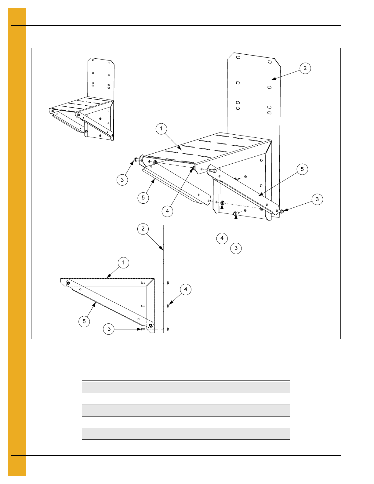
Catwalk Support Assembly at Stiffener
Figure 2A
Catwalk Support Assembly at Stiffener Parts List (D04-0499)
Ref # Part # Description Qty
1 D01-2468 Support at Stiffener 1
2 D01-2469 Stiffener Adapter Plate 1
3 S-9067 Flange Bolt 3/8"-16 x 3/4" ZN Grade 5 7
4 S-968 Flange Nut 3/8"-16 ZN Grade 5 7
5 401-4718-3 Brace at Stiffener 2
6 PNEG-1744 H-Series Catwalk Installation
Page 7

2. Dryer Dimensions, Stiffener and Catwalk Locations
Figure 2G on Page 13
Figure 2H on Page 13
Figure 2G
on Page 13
Figure 2G
on Page 13
Figure 2H
on Page 13
Figure 2G
on Page 13
Dryer Catwalk Layouts
14' Long Dryer Catwalk Layout
Figure 2B
PNEG-1744 H-Series Catwalk Installation 7
Page 8

2. Dryer Dimensions, Stiffener and Catwalk Locations
Figure 2G on Page 13
Figure 2I on Page 14
Figure 2G on Page 13
Figure 2G
on Page 13
Figure 2I
on Page 14
Figure 2G
on Page 13
18' Long Dryer Catwalk Layout
Figure 2C
8 PNEG-1744 H-Series Catwalk Installation
Page 9

2. Dryer Dimensions, Stiffener and Catwalk Locations
Figure 2G on Page 13
Figure 2H on Page 13
Figure 2G
on Page 13
Figure 2G
on Page 13
Figure 2G
on Page 13
Figure 2H
on Page 13
Figure 2G
on Page 13
Figure 2G
on Page 13
Figure 2H
on Page 13
Figure 2H
on Page 13
20' Long Dryer Catwalk Layout
Figure 2D
PNEG-1744 H-Series Catwalk Installation 9
Page 10

2. Dryer Dimensions, Stiffener and Catwalk Locations
Figure 2G
on Page 13
Figure 2H
on Page 13
Figure 2G
on Page 13
Figure 2H
on Page 13
Figure 2G
on Page 13
Figure 2G
on Page 13
Figure 2H
on Page 13
Figure 2G
on Page 13
Figure 2H
on Page 13
Figure 2G
on Page 13
22' Long Dryer Catwalk Layout
Figure 2E
10 PNEG-1744 H-Series Catwalk Installation
Page 11

2. Dryer Dimensions, Stiffener and Catwalk Locations
Figure 2I
on Page 14
Figure 2G
on Page 13
Figure 2G
on Page 13
Figure 2H
on Page 13
Figure 2H
on Page 13
Figure 2G
on Page 13
Figure 2I
on Page 14
Figure 2G
on Page 13
Figure 2H
on Page 13
Figure 2G
on Page 13
Figure 2H
on Page 13
Figure 2G
on Page 13
26' Long Dryer Catwalk Layout
Figure 2F
PNEG-1744 H-Series Catwalk Installation 11
Page 12

2. Dryer Dimensions, Stiffener and Catwalk Locations
Dryer Size vs Support Attachments Needed
Dryer
Length
14'
18'
20'
22'
26'
# of Modules
2 4' 0 2 4 2 0
34'0 4840
2 4' 4 0 4 0 2
34'8 0804
2 2' 0 4 6 4 0
32'0 81280
2 4' 0 4 6 4 0
34'0 81280
2 2' 2 4 6 4 2
32'4 81284
Corner
Length
6' Catwalk
Sections
8' Catwalk
Sections
Figure 2G
on Page 13
Figure 2H
on Page 13
Figure 2I
on Page 14
Figure 2G on Page 13 = D01-2425. Used at the edges of both 6' and 8' catwalk sections.
Figure 2H on Page 13 = D01-2437. Used at center of 8' catwalk sections. Note that 6' catwalk sections do
not require center supports.
Figure 2I on Page 14 = Support for catwalk edge locations without a stiffener. (As seen on Page 14 of
layout for new stiffener supports.)
12 PNEG-1744 H-Series Catwalk Installation
Page 13

2. Dryer Dimensions, Stiffener and Catwalk Locations
Truss Bracket Attachments for Channel Supports
Truss Bracket, Catwalk Section Edge Locations
Figure 2G
Truss Bracket, Catwalk 8' Section Center Locations
Figure 2H
PNEG-1744 H-Series Catwalk Installation 13
Page 14

2. Dryer Dimensions, Stiffener and Catwalk Locations
Catwalk Support Installation for Locations with No Stiffeners
Figure 2I Typical Catwalk Support Installation where no Stiffener is Installed
14 PNEG-1744 H-Series Catwalk Installation
Page 15

2. Dryer Dimensions, Stiffener and Catwalk Locations
Catwalk Support Installation for Locations with No Stiffeners Parts List
Ref # Part # Description Qty
1 D31-0055 Column Bulkhead 1
2 401-4713-4 Catwalk Section 1
3 401-4753-0 Adapter Channel Support 4
4 401-4717-5 Support Angle 2
5 401-4719-1 Brace at Dryer 2
6 S-9067 Flange Bolt 3/8"-16 x 3/4" ZN Grade 5 8
7 S-968 Flange Nut 3/8"-16 ZN Grade 5 8
8 401-4720-9 Filler Plate 1
9 325-2091-8 Channel - Support 1
10 S-7645 Carriage Bolt 5/16"-18 x 3/4" ZN Grade 5 20
11 S-3611 Flange Nut 5/16"-18 ZN YDP 22
12 S-6606 Flange Bolt 5/16"-18 x 3/4" ZN Grade 5 2
PNEG-1744 H-Series Catwalk Installation 15
Page 16

2. Dryer Dimensions, Stiffener and Catwalk Locations
Catwalk Locations
Middle Module Location
Figure 2J Location of Catwalk for Middle Module
Middle Module Location Parts List
Ref # Part # Description Qty
1 SS-692308 9-5 Gauge 2 Ring 1
2 SS-7053 N.S. 8 Gauge Splice 2
3 D01-0872 Stiffener Attach Angle 1
4 D01-2468 Support at Stiffener 1
5 D01-2469 Stiffener Adapter Plate 1
6 S-9067 Flange Bolt 3/8"-16 x 3/4" ZN Grade 5 13
7 S-968 Flange Nut 3/8"-16 ZN Grade 5 13
8 401-4718-3 Brace at Stiffener 2
16 PNEG-1744 H-Series Catwalk Installation
Page 17

Top Module Location
2. Dryer Dimensions, Stiffener and Catwalk Locations
Figure 2K Location of Catwalk for Top Module
Top Module Location Parts List
Ref # Part # Description Qty
1 SS-692308 9-5 Gauge 2 Ring 1
2 SS-7053 N.S. 8 Gauge Splice 1
3 D01-2468 Support at Stiffener 1
4 401-4718-3 Brace at Stiffener 2
5 S-9067 Flange Bolt 3/8"-16 x 3/4" ZN Grade 5 13
6 S-968 Flange Nut 3/8"-16 ZN Grade 5 13
7 D01-2469 Stiffener Adapter Plate 1
PNEG-1744 H-Series Catwalk Installation 17
Page 18

3. Installation Instructions
For Step 1, please refer to the instructions included in the original manual. Follow Step 2 in this
supplement. Then, return to the original manual for Steps 4-8. (Step 3 in the original manual is
obsolete for dryers without buttresses.)
Step 2: Build catwalk support assemblies (part numbers: D04-0499, D01-2425 and D01-2437). Refer to
Table on Page 12 to determine the number of support assemblies and catwalk platforms needed for the
dryer, based upon its length and the number of modules.
Step 3: To install the assemblies on the dryer: A two-stack dryer will have one catwalk on the top module.
A three-stack dryer will have one catwalk on the middle module, as well as one on the top module.
NOTE: There are pla ces where you must install supports where there is no stiffener. (See Figure 2I
on Page 14.) To determine if this situation is applicable to the particular dryer, please refer to
Table on Page 12, as well as dryer layouts and locate the dryer size.
Now, return to the original manual for Steps 4-8.
To install the catwalk support assembly on the middle module, measure 17. 54" from the top of the stiffener
to the top of the assembly (D04-0499). Use the hardware referenced in Figure 2J on Page 16.
To install the catwalk support assembly on the top module, measure 16.57" from the top of the stiffener to
the top of the assembly (D04-0499). Use the hardware referenced in Figure 2K on Page 17.
Once all supports are in place, install catwalk sections as indicated in Table on Page 12 and dryer catwalk
layouts, using the appropriate layout length.
Step 9: On the truss bracket, install the plate with the hole
See Figure 2G on Page 13 for these connections and Table on Page 12 for the quantities required.
On the truss bracket, install the plate without the hole
of the catwalk. See Figure 2H on Page 13 for these connections and Table on Page 12 for the
quantities required.
Go to Step 13 of the existing manual to finish the hand rail installation.
when there is a gap between catwalk sections.
where the support needs to go in the center
18 PNEG-1744 H-Series Catwalk Installation
Page 19

4. Warranty
9101239_1_CR_rev7.DOC (revised July 2009)
GSI Group, LLC Limited Warranty
The GSI Group, LLC (“GSI”) warrants products which it manufactures to be free of defects in materials and workmanship
under normal usage and conditions for a period of 12 months after sale to the original end-user or if a foreign sale,
14 months from arrival at port of discharge, whichever is earlier. The end-user’s sole remedy (and GSI’s only obligation)
is to repair or replace, at GSI’s option and expense, products that in GSI’s judgment, contain a material defect in materials
or workmanship. Expenses incurred by or on behalf of the end-user without prior written authorization from the GSI
Warranty Group shall be the sole responsibility of the end-user.
Warranty Extensions:
The Limited Warranty period is extended for the following products:
Product Warranty Period
Performer Series Direct Drive Fan Motor 3 Years
AP Fans and Flooring
Cumberland
Feeding/Watering
Systems
Grain Systems Grain Bin Structural Design 5 Years
Grain Systems
Farm Fans
Zimmerman
All Fiberglass Housings Lifetime
All Fiberglass Propellers Lifetime
Feeder System Pan Assemblies 5 Years **
Feed Tubes (1-3/4" and 2.00") 10 Years *
Centerless Augers 10 Years *
Watering Nipples 10 Years *
Portable and Tower Dryers 2 Years
Portable and Tower Dryer Frames and
Internal Infrastructure †
5 Years
* Warranty prorated from list price:
0 to 3 years - no cost to end-user
3 to 5 years - end-user pays 25%
5 to 7 years - end-user pays 50%
7 to 10 years - end-user pays 75%
** Warranty prorated from list price:
0 to 3 years - no cost to end-user
3 to 5 years - end-user pays 50%
† Motors, burner components
and moving parts not included.
Portable dryer screens included.
Tower dryer screens not included.
GSI further warrants that the portable and tower dryer frame and basket, excluding all auger and auger drive components,
shall be free from defects in materials for a period of time beginning on the twelfth (12
and continuing until the sixtieth (60
th
) month from the date of purchase (extended warranty period). During the extended
th
) month from the date of purchase
warranty period, GSI will replace the frame or basket components that prove to be defective under normal conditions
of use without charge, excluding the labor, transportation, and/or shipping costs incurred in the performance of this
extended warranty.
Conditions and Limitations:
THERE ARE NO WARRANTIES THAT EXTEND BEYOND THE LIMITED WARRANTY DESCRIPTION SET FORTH
ABOVE. SPECIFICALLY, GSI MAKES NO FURTHER WARRANTY OF ANY KIND, EXPRESS OR IMPLIED,
INCLUDING, WITHOUT LIMITATION, WARRANTIES OF MERCHANTABILITY OR FITNESS FOR A PARTICULAR
PURPOSE OR USE IN CONNECTION WITH: (I) PRODUCT MANUFACTURED OR SOLD BY GSI OR (II) ANY ADVICE,
INSTRUCTION, RECOMMENDATION OR SUGGESTION PROVIDED BY AN AGENT, REPRESENTA TIVE OR
EMPLOYEE OF GSI REGARDING OR RELATED TO THE CONFIGURATION, INSTALLATION, LAYOUT, SUITABILITY
FOR A PARTICULAR PURPOSE, OR DESIGN OF SUCH PRODUCTS.
GSI shall not be liable for any direct, indirect, incidental or consequential damages, including, without limitation, loss of
anticipated profits or benefits. The sole and exclusive remedy is set forth in the Limited Warranty, which shall not exceed
the amount paid for the product purchased. This warranty is not transferable and applies only to the original end-user. GSI
shall have no obligation or responsibility for any representations or warranties made by or on behalf of any dealer, agent
or distributor.
GSI assumes no responsibility for claims resulting from construction defects or unauthorized modifications to products
which it manufactured. Modifications to products not specifically delineated in the manual accompanying the equipment at
initial sale will void the Limited Warranty.
This Limited Warranty shall not extend to products or parts which have been damaged by negligent use, misuse, alteration,
accident or which have been improperly/inadequately maintained. This Limited Warranty extends solely to products
manufactured by GSI.
Prior to installation, the end-user has the responsibility to comply with federal, state and local codes which apply to the
location and installation of products manufactured or sold by GSI.
PNEG-1744 H-Series Catwalk Installation 19
Page 20

This equipment shall be installed in accordance with
the current installation codes and applicable
regulations which should be carefully followed in all
cases. Authorities having jurisdiction should be
consulted before installations are made.
Copyright © 2010 by GSI Group
Printed in the USA
GSI Group
1004 E. Illinois St.
Assumption, IL 62510-0020
Phone: 1-217-226-4421
Fax: 1-217-226-4420
www.gsiag.com
 Loading...