

Page 1
PNEG-1735
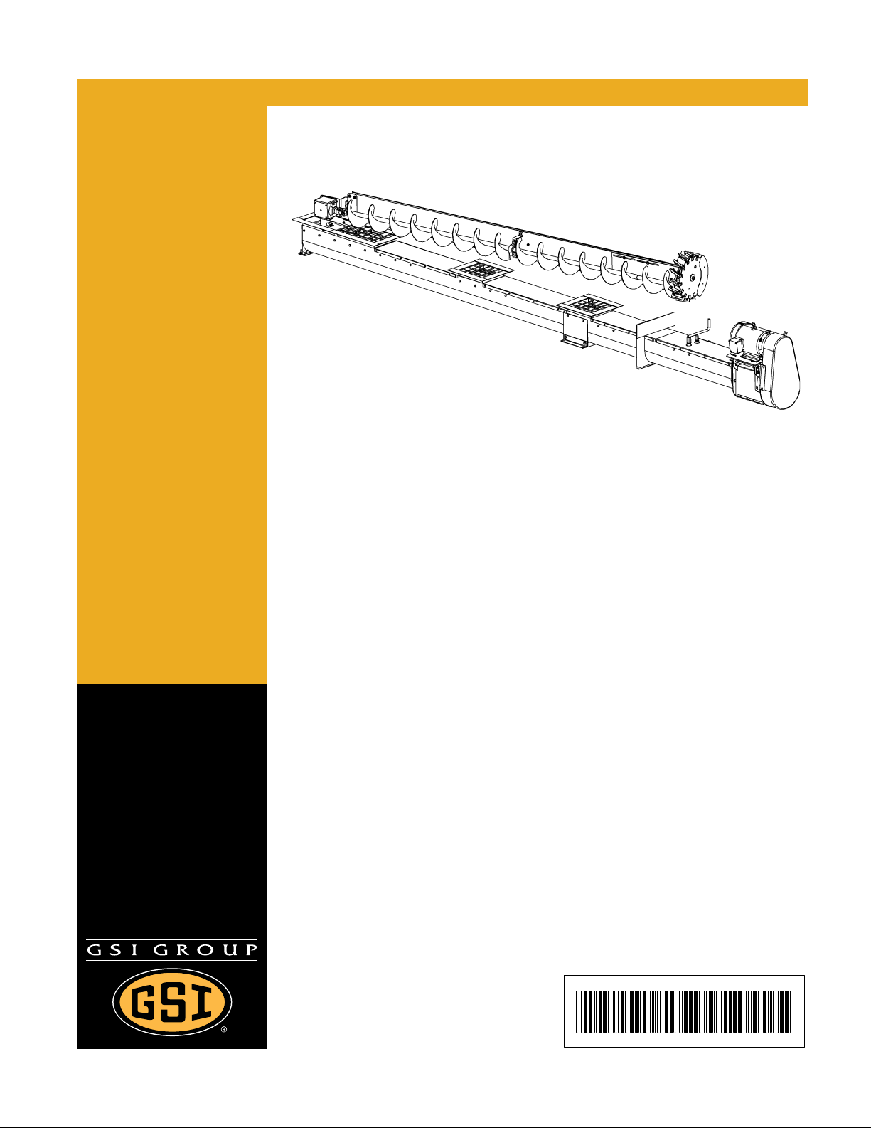
U-Trough Direct Gear Drive Bin
Sweep Auger Unload Systems
Installation Instructions and
Operator’s Manual
PNEG-1735
Date: 01-18-10
Page 2

2 PNEG-1735 U-Trough Direct Ge ar Drive Bin Sweep Auger Unload Systems
Page 3

Table of Contents
Contents
Chapter 1 Safety .................................................................................................................................................. 4
Safety Guidelines .......................................................................................................................... ... .. 4
Operator Qualifications .................................................... ... ... .... ... ................................................ ... .. 9
Chapter 2 Decals ............................................................................................................................................... 10
Safety Decal Location ..... .... ... ... ... .... ... ... ... ... .................................................................................... 10
Chapter 3 Machine Components ..................................................................................................................... 11
U-Trough Unload Components ........... ... ... ... .... ... ... ... .... .......................................... ... ... ... ... .... ... ...... 11
Chapter 4 Installation ....................................................................................................................................... 12
Installation Under Aeration Floor ...................... ... ... ... .... ... ... ... .... ... ................................................... 12
Installation in Concrete Foundation .................. ... ... ... .... ... ... ... .... ... ... ... ... .... ... ... ... ............................. 14
Sweep Drive ........................... ... ... .... ... ... ... ... .... ...................................... .... ... ... ... .... ... ... ................... 16
Sweep Arm .......................... ... ... ... .......................................... .... ...................................................... 18
Horizontal Drive Unit ........................................................................................................................ 25
Incline Elbow ....................................... ... ... ... .... .......................................... ... ................................... 27
Chapter 5 Power Requirements ....................................................................................................................... 28
Electric Drive .................................................................................................................................... 28
Chapter 6 Operation ......................................................................................................................................... 30
Pre-operation Check List .................................................................................................................. 30
Chapter 7 Service .............................................................................................................................................. 33
Gearbox Oil Level ............................................................................................................................ 33
Grease Points ........... ... ... .... ... ... ... .... ................................................................................................ 34
Chapter 8 Unload Dimensions ......................................................................................................................... 35
U-Trough Unload Dimensions ................................... .... ... ... ... .... ... ... ... ... .... ... ... ... .... ... ... ... ... .... ......... 35
Bin Sweep Dimensions .................................................................................................................... 36
Chapter 9 Warranty ........................................................................................................................................... 37
PNEG-1735 U-Trough Direct Gear Drive Bin Sweep Auger Unload Systems 3
Page 4
1. Safety
This is the safety alert symbol. It is used to alert you to
potential personal injury hazards. Obey all safety
messages that follow this symbol to avoid possible
injury or death.
WARNING indicates a potentially hazardous situation
which, if not avoided, could result in death or serious injury.
CAUTION indicates a potentially hazardous situation which,
if not avoided, may result in minor or moderate injury.
CAUTION used without the safety alert symbol indicates a
potentially hazardous situation which, if not avoided, may
result in property damage.
NOTE indicates information about the equipment that you
should pay special attention.
DANGER indicates an imminently hazardous situation
which, if not avoided, will result in death or serious injury.
Personnel operating or working around this equipment should read this manual. This
manual must be delivered with the equipment to its owner. Failure to read this manual
and its safety instructions is a misuse of the equipment.
WARNING! BE ALERT!
Safety Guidelines
This manual contains information that is important for you, the owner/operator, to know and understand.
This information relates to protecting personal safety and preventing equipment problems. It is the
responsibility of the owner/operator to inform anyone operating or working in the area of this equipment
of these safety guidelines. To help you recognize this information, we use the symbols that are defined
below. Please read the manual and pay attention to these sections. Failure to read this manual and its
safety instructions is a misuse of the equipment and may lead to serious injury or death.
4 PNEG-1735 U-Trough Direct Ge ar Drive Bin Sweep Auger Unload Systems
Page 5
1. Safety
Follow Safety Instructions
Carefully read all safety messages in this manual and
safety signs on your machine. Keep signs in good
condition. Replace missing or damaged safety signs. Be
sure new equipment components and repair parts include
the current safety signs. Replacement safety signs are
available from the manufacturer.
Learn how to operate the machine and how to use controls
properly. Do not let anyone operate without instruction.
Keep your machinery in proper working condition.
Unauthorized modifications to the machine may impair
the function and/or safety and affect machine life.
If you do not understand any part of this manual or need
assistance, contact your dealer.
Read and Understand Manual
Practice Safe Maintenance
Understand service procedures before doing work. Keep area
clean and dry.
Never lubricate, service, or adjust machine while it is in operation.
Keep hands, feet and clothing away from rotating parts.
Keep all parts in good condition and properly installed. Fix
damage immediately . Replace worn or broken p arts. Remove any
built up grease oil and debris.
Maintain Equipment
and Work Area
Install Equipment Properly
This equipment shall be installed in accordance with the
current installation codes and applicable regulations which
should be carefully followed in all cases. Authorities having
jurisdiction should be consulted before installations
are made.
Follow Building Codes
Rotating Flight
Grain augers can kill or dismember.
Keep clear of all augers and never enter the bin unless all
power is disconnected and locked out. Failure to do so will
result in serious injury or death.
Rotating Flight
PNEG-1735 U-Trough Direct Gear Drive Bin Sweep Auger Unload Systems 5
Page 6
1. Safety
Keep Hands Away from Moving Parts
DO NOT put hand or arm in hopper. Rotating auger can
crush and dismember.
DO NOT put any kind of tool inside hopper to try and clear
debris while the auger is running. Damage to the equipment
will result.
ALWAYS turn off and lock out all power sources before
servicing equipment.
Keep all shields and covers in place during operation.
Rotating Auger
Operate Motor Properly
To avoid serious injury or death, stay away from unit and make sure
everyone is clear of the equipment before starting or operating
the unit.
All electrical connections should be made in accordance with
the National Electric Code. Be sure equipment and bins are
properly grounded.
Do not operate electric motor equipped units until motors are
properly grounded.
Disconnect power on electrical driven units before resetting
motor overloads.
Do not repetitively stop and start the drive in order to free a plugged
condition. Jogging the drive in this manner can damage the
equipment and/or drive components.
Electric Shock Hazard
Prepare for Emergencies
Be prepared if fire starts.
Keep a first aid kit and fire extinguisher handy.
Keep emergency numbers for doctors, ambulance service,
hospital and fire department near your telephone.
Keep Emergency Equipment
Quickly Accessible
6 PNEG-1735 U-Trough Direct Ge ar Drive Bin Sweep Auger Unload Systems
Page 7
1. Safety
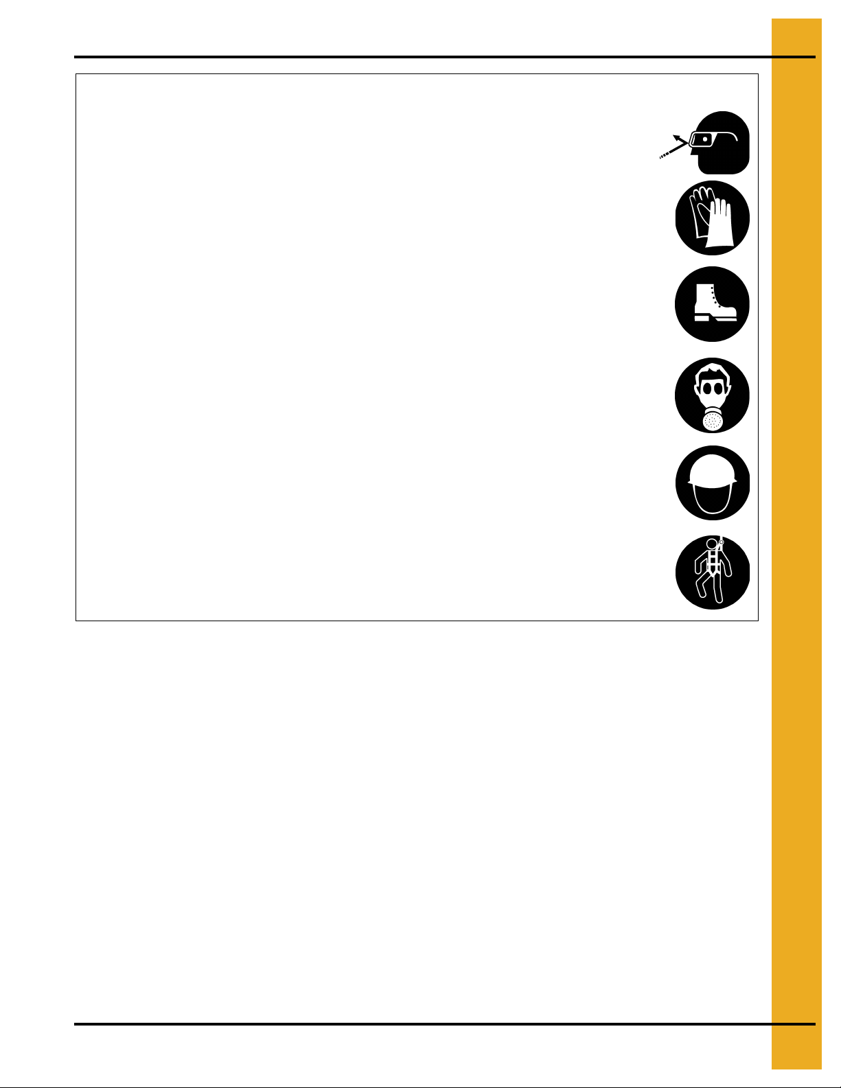
Wear Protective Clothing
Wear close fitting clothing and safety equipment appropriate
to the job.
Remove all jewelry.
Long hair should be tied up and back.
Safety glasses should be worn at all times to protect eyes
from debris.
Wear gloves to protect your hands from sharp edges on
plastic or steel parts.
Wear steel toe boots to help protect your feet from falling
debris. Tuck in any loose or dangling shoe strings.
A respirator may be needed to prevent breathing potentially
toxic fumes and dust.
Wear hard hat to help protect your head.
Wear appropriate fall protection equipment when working at
elevations greater than six feet (6').
Eye Protection
Gloves
Steel Toe Boots
Respirator
Hard Hat
Fall Protection
PNEG-1735 U-Trough Direct Gear Drive Bin Sweep Auger Unload Systems 7
Page 8

1. Safety
Operate Unload Equipment Properly
• Untrained operators subject themselves and others to SERIOUS INJURY
or DEATH. NEVER allow untrained personnel to operate this equipment.
• NEVER work alone.
• Keep children and other unqualified personnel out of the working
area at ALL times.
• Make sure ALL equipment is locked in position before operating.
• NEVER start equipment until ALL persons are clear of the work area.
• Keep hands and feet away from the auger intake and other moving parts.
• NEVER attempt to assist machinery operation or to remove trash from equipment while
in operation.
• Be sure all operators are adequately rested and prepared to perform all functions of operating
this equipment.
• NEVER allow any person intoxicated or under the influence of alcohol or drugs to operate
the equipment.
• Make sure someone is nearby who is aware of the proper shut down sequence in the event of an
accident or emergency.
• ALWAYS think before acting. NEVER act impulsively around the equipment.
• NEVER allow anyone inside a bin, truck or wagon which is being unloaded by an auger or
conveyor. Flowing grain can trap and suffocate in seconds.
• Use ample overhead lighting after sunset to light the work area.
• Keep area around intake free of obstacles such as electrical cords, blocks, etc., that might
trip workers.
• ALWAYS lock out ALL power to the equipment when finished unloading a bin.
• Be aware of pinch points. A pinch point is a narrow area between two surfaces that is likely to trap
or catch objects and so is a potential safety hazard.
Operate Unload
Equipment Safely
8 PNEG-1735 U-Trough Direct Ge ar Drive Bin Sweep Auger Unload Systems
Page 9
Operator Qualifications
A. The User/Operator must be competent and experienced to operate this (or auger) equipment.
Anyone who works with or around augers must have good common sense in order to be qualified.
These persons must also know and meet all other qualifications, such as:
i. Any person who has not read and/or does not understand all operation and safety procedures
is not qualified to operate any auger systems.
ii. Certain regulations apply to personnel operating power machinery. Personnel under the age
of 18 years may not operate power machinery, including augers. It is your responsibility, as
owner and/or supervisor, to know what these regulations are in your area or situation.
iii. Unqualified or incompetent persons are to remain out of the work area.
iv. O.S.H.A. (Occupational Safety and Health Administration) regulations state: “At the time of
initial assignment and at least annually thereafter, the employer shall instruct every employee
in the safe operation and servicing of all equipment with which the employee is, or will be
involved”. (Federal Occupational Safety and Health Standards for Agriculture. Subpart D,
Section 1928.57 (a) (6)).
1. Safety
B. As a requirement of O.S.H.A., it is necessary for the employer to train the employee in the safe
operating and safety procedures for this auger. The sign-off sheet is provided for your convenience
and personal record keeping. All unqualified persons are to stay out of the work area at all times.
It is strongly recommended that another qualified person who knows the shut down procedure is
in the area in the event of an emergency.
Date Employee Name Supervisor Name
PNEG-1735 U-Trough Direct Gear Drive Bin Sweep Auger Unload Systems 9
Page 10
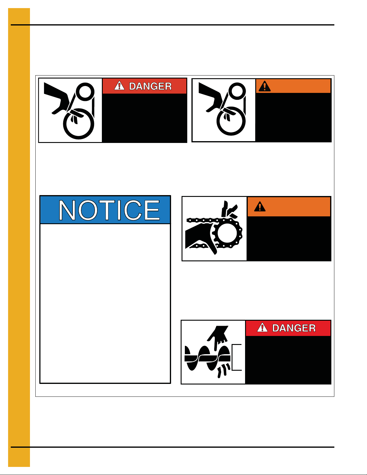
2. Decals
SHEAR POINT
Keep hands clear of moving
parts. Do not operate with
guard removed. Disconnect
and lockout power before
servicing.
DC-994
1. READ AND UNDERSTAND THE OPERATOR’S MANUAL
AND ALL SAFETY INSTRUCTIONS.
6.
DO NOT ALLOW CHI LDREN IN THE AREA O F OPERATION.
2.
DO NOT OPERATE WHILE UNDER THE INFLUENCE OF
DRUGS OR ALCOHOL.
4.
ALLOW ONLY TRAINED AUTHORIZED PERSONNEL IN
THE OPERATING AREA.
7.
KEEP HANDS, FEET AND CLOTHING AWAY FROM
MOVING PARTS.
10.
MAKE CERTAIN ALL ELECTRIC MOTORS ARE GROUNDED.
11.
REPLACE ALL WORN OR DAMAGED LABELS IMMEDIATELY.
9.
DISCONNECT POWER PRIOR TO RESETTING ANY
MOTOR OVERLOAD.
3.
DO NOT OPERATE UNLESS ALL SAFETY EQUIPMENT,
SWITCHES, GUARDS AND SHIELDS ARE SECURELY IN
PLACE AND OPERATIONAL.
5.
ANY ELECTRICAL WIRING OR SERVICE WORK MUST
BE PERFORMED BY A QUALIFIED ELECTRICIAN. IT MUST
MEET ALL STATE AND LOCAL ELECTRICAL CODES.
8.
DISCONNECT AND LOCKOUT POWER BEFORE
MAKING ANY ADJUSTMENTS OR PERFORMING ANY
SERVICE WORK.
DC-137 9
SHEAR POINT
Keep clear of rotating auger and
moving parts.
Do not remove or modify guards.
Disconnect and lock out power
before servicing.
Failure to do so will result in
serious INJURY or DEATH.
DC-1381
DC-994
DC-995
DC-1386
DC-1381
DC-1379
Safety Decal Location
The types of decals and locations on the equipment are shown below. Good safety requires that you
familiarize yourself with the various safety decals, the type of warning and the area or particular function
that related to the area, that requires your SAFETY AWARNESS.
WARNING
SHEAR POINT
Keep hands clear of moving
parts. Do not operate with
guard removed. Disconnect
and lockout power before
servicing.
DC-995
WARNING
SHEAR POINT
Moving parts can
crush and cut. Keep
hands clear of
sprocket and chain.
10 PNEG-1735 U-Trough Direct Gear Drive Bin Sweep Auger Unload Systems
DC-1386
Page 11
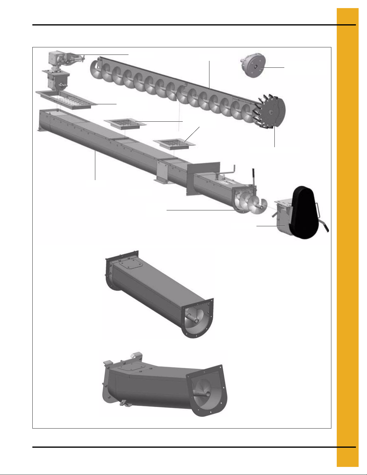
U-Trough Unload Components
Gearbox
Sweep
Center floor
flange
Trough
Bin plate
Unload
flight
Drive unit
Intermediate
floor flange
Elevator drive wheel
Sweep reduction
drive wheel
Incline elbow
U-Tr ough extension
3. Machine Components
PNEG-1735 U-Trough Direct Gear Drive Bin Sweep Auger Unload Systems 11
Figure 3A
Page 12
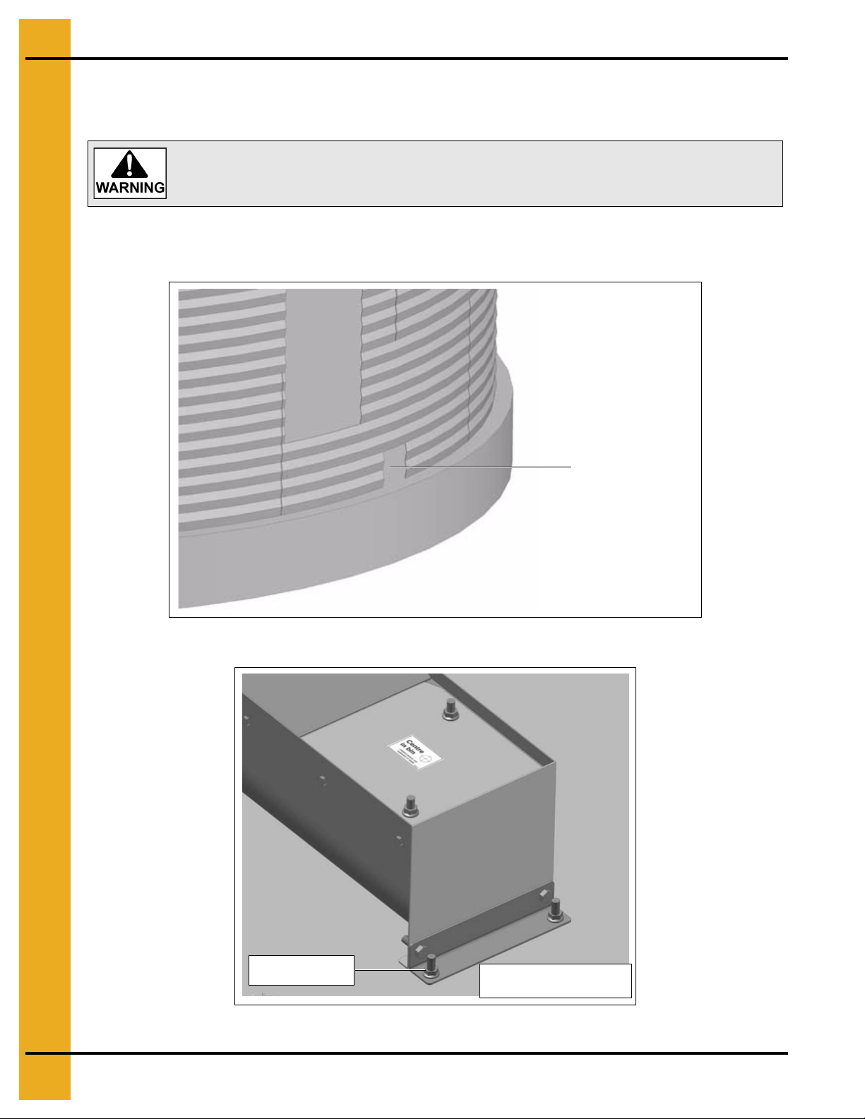
4. Installation
Do not cut across bolted seams.
Cut 12" x 12" access
through bin wall
U-Trough unload. Center
in bin and anchor to floor.
Concrete anchor
bolt
Installation Under Aeration Floor
1. Cut 12" x 12" (30 cm x 30 cm) opening in bin wall where unload is to exit bin. (See Figure 4A.)
2. Insert unload and center it in the bin.
3. Secure unload with anchor bolts (not supplied) to the bin foundation.
Figure 4A
Figure 4B
12 PNEG-1735 U-Trough Direct Gear Drive Bin Sweep Auger Unload Systems
Page 13

4. Installation
Ensure clearance between
bottom of floor flange and gate
U-Trough center floor flange comes in two (2) parts.
Before installing bolt together with joiner strips provided.
4. Layout aeration floor and cut opening around gates, approximately 1" larger than gate openings.
5. Attach floor flanges to floor with self-drilling screws.
6. Ensure that there is a minimum of 1/4" clearance between the bottom e dge of th e floor flange and
the unload.
Figure 4C
Figure 4D
Figure 4E
Figure 4F
PNEG-1735 U-Trough Direct Gear Drive Bin Sweep Auger Unload Systems 13
Page 14

4. Installation
Figure 4G U-Trough Unload
Installation in Concrete Foundation
Concrete Knock-out
1. When constructing the concrete foundation, form a kn ock-out for the unload as shown
on Page 15
manner unloads can be removed at a later date.
2. Cross section of foundation knock-out.
a. Center the unload in the bin foundation.
b. Anchor to the bottom of the knock-out with concrete anchor bolts (not provided).
c. Install floor flanges over the gates.
d. Use wood or metal planking to cover exposed unload between gates.
. This is the prefered method of installing the unload in concrete. When installed in this
in Figure 4H
14 PNEG-1735 U-Trough Direct Gear Drive Bin Sweep Auger Unload Systems
Page 15

4. Installation
Center in bin
Planking
Figure 4H
Figure 4I
Figure 4J
Unload Cast Directly into Concrete
When casting unloads directly into concrete, center in the bin and adjust the height as shown
in Figure 4K. Use floor flanges to form around the gate openings.
Figure 4K U-Trough Unload in Concrete
PNEG-1735 U-Trough Direct Gear Drive Bin Sweep Auger Unload Systems 15
Page 16

4. Installation
Shifter arm
Cover plate can
be removed to
access lower
gearbox area.
Slot
Gearbox shifter arm in shifter slot
Sweep Drive
Install gearbox into unload. Ensure that the shifter arm on the gearbox slides into the sh ifter slot on the
unload. Secure gearbox with two (2) flange nuts.
Figure 4L
Figure 4M
Figure 4N
16 PNEG-1735 U-Trough Direct Gear Drive Bin Sweep Auger Unload Systems
Page 17

4. Installation
Adjust shifter linkage
Figure 4O
1. Adjust gearbox shifter linkage such that when shifting into OFF position, there is some resistance
when the lever overcenters into the OFF position.
2. Do not over tighten as this can damage the gearbox.
3. Before operating ensure that the gearbox is shifting properly.
4. Shift into OFF, turn unload flight by hand.
5. The top gearbox should not be turning.
6. Shift into ON position, top gearbox should turn when unload flight is turned.
PNEG-1735 U-Trough Direct Gear Drive Bin Sweep Auger Unload Systems 17
Figure 4P Gearbox Shifter in ON Position
Figure 4Q Gearbox Shifter in OFF Position
Page 18

4. Installation
Length adjustment
Height
adjustment
Height adjustment
Side adjustment
Sweep Arm
Adjustments
1. Attach sweep to sweep gearbox drive.
2. To adjust overall sweep length, slack off four (4) mounting bolts holding adjuster plate to sweep and
slide in or out to set length.
3. The height of the sweep back plate can be adjusted both at the wheel and at the drive end.
Figure 4R
Figure 4S
Figure 4T
Figure 4U
18 PNEG-1735 U-Trough Direct Gear Drive Bin Sweep Auger Unload Systems
Page 19

NOTES
PNEG-1735 U-Trough Direct Gear Drive Bin Sweep Auger Unload Systems 19
Page 20

4. Installation
Two (2) Section Bin Sweeps (54'-75' Diameter)
Figure 4V
20 PNEG-1735 U-Trough Direct Gear Drive Bin Sweep Auger Unload Systems
Page 21

Two (2) Section Bin Sweeps (54'-75' Diameter) Parts List
Ref # Description Qty
1 Sweep Back Plate 60' (Inner) 1
2 Sweep Back Plate 60' (Outer) 1
3 Back Plate Joiner 1
4 Sweep Brace 2
5 Sweep Wheel Flight 9" 1
6 1-1/2" Split PB Assembly 2
7 Sweep Flight 9" 1
8 Sweep Brace Mount 2
9 Hex Nut Grade 5 UNC 3/4" 6
10 6" Wheel with 3/4" Bearing 1
11 Flat Washer 3/4" Plated 6
12 Bolt Grade 5 UNC Plated 3/4" x 5" 1
4. Installation
13 U-Nut 3/8" 8
14 Bolt Grade 5 UNC Plated 1/2" x 1-1/2" 4
15 Lock Washer 1/2" Plated 4
16 Hex Nut Grade 5 UNC 1/2" 4
17 Flat Washer 3/8" Plated 10
18 Lock Washer 3/8" Plated 33
19 Bolt Grade 5 UNC Plated 3/8" x 1-1/2" 2
20 Hex Nut Grade 5 UNC 3/8" 11
21 Carriage Bolt UNC Plated 3/8" x 1" 8
22 Sweep Center Plate Joiner 1
23 Sweep Center Mount Inner Plate 1
24 Sweep Center Mount 1
25 Bolt Grade 5 UNC Plated 3/8" x 1" 23
26 Sweep End Adjuster Plate 1
27 Sweep PB Mount 9" 2
28 Lock Washer 3/4" Plated 3
PNEG-1735 U-Trough Direct Gear Drive Bin Sweep Auger Unload Systems 21
Page 22

4. Installation
Sweep Drive Wheel
Elevator Drive Wheel
Figure 4W Mounted for 7-1/4" Flight Position Figure 4X Mounted for 8-1/4" and 9" Flight Position
Reduction Drive Wheel
Figure 4Y 7-1/4" Flight Mounting
Figure 4Z 8-1/4" and 9" Flight Mounting
22 PNEG-1735 U-Trough Direct Gear Drive Bin Sweep Auger Unload Systems
Page 23

4. Installation
Install bolt containing a through hole at height shown.
Feed cable through hole and reconnect to sweep stop.
Sweep Stop
Mount sweep stop such that it will stop the sweep before it reaches the walk through door.
Figure 4AA
Figure 4AB
PNEG-1735 U-Trough Direct Gear Drive Bin Sweep Auger Unload Systems 23
Figure 4AC
Page 24

4. Installation
Figure 4AD
Figure 4AE
ONLY OPERATE SWEEP STOP FROM OUTSIDE THE BIN.
24 PNEG-1735 U-Trough Direct Gear Drive Bin Sweep Auger Unload Systems
Page 25

4. Installation
Flight rotation
Bearing locking collar
Horizontal Drive Unit
1. Attach drive unit to unload.
2. Attach drive shaft and bearing.
3. Lock bearing to shaft with eccentric locking collar. The eccentric locking collar is locked to the shaft
with a punch and hammer (turn the collar clockwise to tighten) as well as with a locking set screw.
4. Note the flight rotation when installing and wiring the drive motor. Correct rotation is clockwise wh en
looking at the drive unit.
5. Adjust belt tension with clevis on overcenter tensioner.
Figure 4AF
PNEG-1735 U-Trough Direct Gear Drive Bin Sweep Auger Unload Systems 25
Figure 4AG
Page 26

4. Installation
Taper Bore Hub Installation
1. Be sure the tapered cone surfaces of the bushing and inside of pulley are clean and free of grease
and oil.
2. Place bushing in pulley.
3. Place bolts and lock washers loosely in pull-up holes. Bushing remains fully expanded to assure
sliding fit on shaft.
4. With key on shaft slide pulley to desired position on shaft. Be sure heads of bolts are on outside.
5. Tighten bolts alternately and progressively until they are pulled up tight. Tighten to 180 in. lbs.
(20 N-m) torque. Do not allow pulley to be drawn in contact with flange of bushing. There should
be a gap from 1/8" to 1/4".
DO NOT OVER-TIGHTEN.
Figure 4AH
26 PNEG-1735 U-Trough Direct Gear Drive Bin Sweep Auger Unload Systems
Page 27

4. Installation
Support mount clip
Support cable
Support mount clip
Support mount clips
Incline Elbow
1. Attach the incline elbow shaft (hex round) to the unload flight.
2. Attach the incline elbow to the unload.
3. When installing the drive unit on the inline elbow ensure that the flight is adjuste d so that the support
bearing is centered in the flight gap. Slide the incline elbow flight up or down to set this adjustment.
When incline elbows are used with heavy motors it is recommended to provide support back to the
bin with cables (not provided). Support mount clips are provided.
Figure 4AI
Figure 4AJ
PNEG-1735 U-Trough Direct Gear Drive Bin Sweep Auger Unload Systems 27
Page 28

5. Power Requirements
Power requirements are dependent on grain type, condition and moisture level. Power requirements are
suggestions and may vary in specific circumstances. Steps can be taken t o reduce the power needed to
operate the unload or sweep if power available to the site is limited. Operating the unload at a slower
speed and reducing the flow of grain into the unload will reduce power requirement.
Electric Drive
All values in horsepower, (1 HP = 0.746 Kw).
A pulley for the electric drive motor is not provided.
For 1750 RPM motor use 3-1/2" - 3-3/4" diameter pulley, for 1460 RPM motor use 4-1/4" - 4-1/2"
diameter pulley.
For power requirements from 1.5 HP-7.5 HP use a two (2) groove pulley.
For power requirements from 10 HP-25 HP use a three (3) groove pulley.
U-Trough Unload c/w Sweep
Bin
Diameter
15 5 7.5 3 5
18 5 7.5 3 5
19 5 7.5 5 5
21 5 7.5 5 5
24 7.5 7.5 5 5
27 7.5 10 5 7.5
30 7.5 10 5 7.5
33 7.5 10 5 7.5
36 10 10 7.5 7.5
42 10 15 7.5 7.5
48 10 15 7.5 10
54 15 15 7.5 10
60 15 15 10 10
Unload and Sweep 12.4" Flight Pulley Unload and Sweep 18.4" Flight Pulley
Horizontal Drive Unit Incline Drive Unit Horizontal Drive Unit Incline Drive Unit
28 PNEG-1735 U-Trough Direct Gear Drive Bin Sweep Auger Unload Systems
Page 29

Unload Individually
5. Power Requirements
Unload with
12.4" Pulley
Bin Diameter
15 5 3 7.5 5
18 5 3 7.5 5
19 5 5 7.5 5
21 5 5 7.5 5
24 7.5 5 7.5 5
27 7.5 5 10 7.5
30 7.5 5 10 7.5
33 7.5 5 10 7.5
36 10 7.5 10 7.5
42 10 7.5 15 7.5
48 10 7.5 15 10
54 15 7.5 15 10
Horizontal
Drive Unit
9" Diameter 9" Diameter 9" Diameter 9" Diameter
Unload with
18.4" Pulley
Horizontal
Drive Unit
Unload with
12.4" Pulley
Incline
Drive Unit
Unload with
18.4" Pulley
Incline
Drive Unit
60 15 10 15 10
Sweep Individually
Bin Diameter 7-1/4" Diameter 8-1/4" Diameter
15 2 2
18 2 2
19 2 2
21 2 3
24 2 3
27 3 3
30 3 5
33 3 5
36 3 5
42 5 5
48 5 5
54 5 5
60 5 7.5
PNEG-1735 U-Trough Direct Gear Drive Bin Sweep Auger Unload Systems 29
Page 30

6. Operation
Position sweep as
shown before filling.
Pre-operation Check List
1. Before filling the grain bin, check to ensure that all unload components are functioning properly.
2. Rotate drive unit and flight to ensure flight is free of obstruction and rotating smoothly.
3. Open and closed all unload gates to ensure that they are operating freely.
4. LEAVE GATES IN THE CLOSED POSITION WHEN FILLING THE BIN.
5. Operate gearbox shifter to ensure the clutch is functioning properly.
6. GEARBOX SHOULD BE DISENGAGED WHEN FILLING THE BIN.
7. Position the bin sweep above the intermediate gates or such that the interme diate gates are just in
front of the sweep.
8. After the bin is filled with product, keep moisture from entering the grain bin at the center and
draining down into the unload and sweep drive area.
9. Before beginning to unload grain, check the grain condition at the top of the bin. Remove any
clumps of grain as they may restrict flow into the gates.
Figure 6A
30 PNEG-1735 U-Trough Direct Gear Drive Bin Sweep Auger Unload Systems
Page 31

6. Operation
ALWAYS UNLOAD FROM THE CENTER GATE FIRST. Unloading from the
intermediate gates when the bin is still mostly full, causes excessive stress
on the grain bin and can cause the grain bin to be damaged or collapse.
Intermediate gate control
Center gate control
For bin sizes 15'-36' the center gate is controlled independent of the intermediate gates. For bin sizes
42' diameter and larger the intermediate gate closest to the center gate is operated with the center gate
control. When the center gate is 50% open, the next intermediate gate is opened together with the center
gate such. Similarly, the center and next intermediate gate are closed together.
Figure 6B Center Unloading
Figure 6C Off - Center Unloading
PNEG-1735 U-Trough Direct Gear Drive Bin Sweep Auger Unload Systems 31
Figure 6D
Page 32

6. Operation
Gearbox Sweep Operation
Turn OFF unload before shifting gearbox into gear. Ensure that the gearbox shifter has engaged before
starting unload.
Figure 6E Gearbox OFF
Figure 6F Gearbox ON
32 PNEG-1735 U-Trough Direct Gear Drive Bin Sweep Auger Unload Systems
Page 33

Gearbox Oil Level
Vent plug
Side plug
Dipstick
Full line
(Check levels once per season or every 50 hours of operation.)
1. Fill top gearbox to side plug level.
2. Remove cover and fill bottom gearbox to line on dipstick.
3. Gearboxes are factory filled with USDA approved food grade oil ISO 150.
4. Oils such as SAE 80-90 gear oil are acceptable. Do not mix oil types.
7. Service
Figure 7A Top Gearbox
Figure 7B Bottom Gearbox
PNEG-1735 U-Trough Direct Gear Drive Bin Sweep Auger Unload Systems 33
Page 34

7. Service
Gearbox U-joint
Incline elbow
U-joint
Sweep drive
wheel
Sweep drive
wheel
Grease Points
(Grease every 8 hours of operation.)
Figure 7C Figure 7D
Figure 7E
Figure 7F
34 PNEG-1735 U-Trough Direct Gear Drive Bin Sweep Auger Unload Systems
Page 35

All dimensions are in inches unless specified otherwise.
U-Trough Unload Dimensions
8. Unload Dimensions
Figure 8A
Standard
Bin
Diameter
(Feet)
15 1 143.5 110 70 24.4 144.5 187
18 1 160 126.5 86.5 40.9 161 203.5
19 1 166 132.5 92.5 46.9 167 209.5
21 1 178 144.5 104.5 58.9 179 221.5
24 1 196 162.5 122.5 76.9 197 239.5
27 2 214 180.5 140.5 41.4 215 257.5
30 2 232 198.5 158.5 50.4 233 275.5
33 2 250 216.5 176.5 59.4 251 293.5
36 2 268 234.5 194.5 68.4 269 311.5
42 3 304 270.5 230.5 53.6 305 347.5
48 3 339 305.5 265.5 65.3 340 382.5
# of
Intermediate
Gates
AB C D E F
Overall
Unload
Length
Maximum
Bin
Radius
Minimum
Bin
Radius
Distance
Between
Gates
Center of Bin
to Center of
Discharge Horizontal
Drive Unit
Center of Bin
Discharge Incline
to Center of
Drive Unit
54 3 376 342.5 302.5 77.6 377 419.5
60 4 412 378.5 338.5 64.2 413 455.5
PNEG-1735 U-Trough Direct Gear Drive Bin Sweep Auger Unload Systems 35
Page 36

8. Unload Dimensions
Bin Sweep Dimensions
Figure 8B
Nominal Bin
Diameter (Feet)
Minimum Diameter Maximum Diameter Minimum Maximum
15 79.5 88.5 14.0 15.5
16.5 88.5 97.5 15.5 17.0
18 97.5 106.5 17.0 18.5
19.5 106.5 115.5 18.5 20.0
21 115.5 124.5 20.0 21.5
22.5 124.5 133.5 21.5 23.0
24 133.5 142.5 23.0 24.5
25.5 142.5 151.5 24.5 26.0
27 151.5 160.5 26.0 27.5
28.5 160.5 169.5 27.5 29.0
30 169.5 178.5 29.0 30.5
31.5 178.5 187.5 30.5 32.0
33 187.5 196.5 32.0 33.5
34.5 196.5 205.5 33.5 35.0
36 205.5 214.5 35.0 36.5
37.5 214.5 223.5 36.5 38.0
39 223.5 232.5 38.0 39.5
40.5 232.5 241.5 39.5 41.0
42 241.5 250.5 41.0 42.5
43.5 250.5 259.5 42.5 44.0
45 259.5 268.5 44.0 45.5
46.5 268.5 277.5 45.5 47.0
48 277.5 286.5 47.0 48.5
49.5 286.5 295.5 48.5 50.0
51 295.5 304.5 50.0 51.5
52.5 304.5 313.5 51.5 53.0
54 313.5 322.5 53.0 54.5
55.5 322.5 331.5 54.5 56.0
57 331.5 340.5 56.0 57.5
58.5 340.5 349.5 57.5 59.0
60 349.5 358.5 59.0 60.5
Sweep Length (L) (in.)
Bin Diameter Range (ft.) Allowing 4-1/2"
Clearance between Sweep and Bin Wall
36 PNEG-1735 U-Trough Direct Gear Drive Bin Sweep Auger Unload Systems
Page 37

9. Warranty
9101239_1_CR_rev7.DOC (revised July 2009)
GSI Group, LLC Limited Warranty
The GSI Group, LLC (“GSI”) warrants products which it manufactures to be free of defects in materials and workmanship
under normal usage and conditions for a period of 12 months after sale to the original end-user or if a foreign sale,
14 months from arrival at port of discharge, whichever is earlier. The end-user’s sole remedy (and GSI’s only obligation)
is to repair or replace, at GSI’s option and expense, products that in GSI’s judgment, contain a material defect in materials
or workmanship. Expenses incurred by or on behalf of the end-user without prior written authorization from the GSI
Warranty Group shall be the sole responsibility of the end-user.
Warranty Extensions:
The Limited Warranty period is extended for the following products:
Product Warranty Period
Performer Series Direct Drive Fan Motor 3 Years
AP Fans and Flooring
Cumberland
Feeding/Watering
Systems
Grain Systems Grain Bin Structural Design 5 Years
Grain Systems
Farm Fans
Zimmerman
All Fiberglass Housings Lifetime
All Fiberglass Propellers Lifetime
Feeder System Pan Assemblies 5 Years **
Feed Tubes (1-3/4" and 2.00") 10 Years *
Centerless Augers 10 Years *
Watering Nipples 10 Years *
Portable and Tower Dryers 2 Years
Portable and Tower Dryer Frames and
Internal Infrastructure †
5 Years
* Warranty prorated from list price:
0 to 3 years - no cost to end-user
3 to 5 years - end-user pays 25%
5 to 7 years - end-user pays 50%
7 to 10 years - end-user pays 75%
** Warranty prorated from list price:
0 to 3 years - no cost to end-user
3 to 5 years - end-user pays 50%
† Motors, burner components
and moving parts not included.
Portable dryer screens included.
Tower dryer screens not included.
GSI further warrants that the portable and tower dryer frame and basket, excluding all auger and auger drive
components, shall be free from defects in materials for a period of time beginning on the twelfth (12
the date of purchase and continuing until the sixtieth (60
th
) month from the date of purchase (extended warranty period).
th
) month from
During the extended warranty period, GSI will replace the frame or basket components that prove to be defective
under normal conditions of use without charge, excluding the labor, transportation, and/or shipping costs incurred in
the performance of this extended warranty.
Conditions and Limitations:
THERE ARE NO WARRANTIES THAT EXTEND BEYOND THE LIMITED WARRANTY DESCRIPTION SET FORTH
ABOVE. SPECIFICALLY, GSI MAKES NO FURTHER WARRANTY OF ANY KIND, EXPRESS OR IMPLIED,
INCLUDING, WITHOUT LIMITATION, WARRANTIES OF MERCHANTABILITY OR FITNESS FOR A PARTICULAR
PURPOSE OR USE IN CONNECTION WITH: (I) PRODUCT MANUFACTURED OR SOLD BY GSI OR (II) ANY
ADVICE, INSTRUCTION, RECOMMENDATION OR SUGGESTION PROVIDED BY AN AGENT, REPRESENTATIVE
OR EMPLOYEE OF GSI REGARDING OR RELATED TO THE CONFIGURATION, INSTALLATION, LAYOUT,
SUITABILITY FOR A PARTICULAR PURPOSE, OR DESIGN OF SUCH PRODUCTS.
GSI shall not be liable for any direct, indirect, incidental or consequential damages, including, without limitation, loss of
anticipated profits or benefits. The sole and exclusive remedy is set forth in the Limited Warranty, which shall not exceed
the amount paid for the product purchased. This warranty is not transferable and applies only to the original end-user.
GSI shall have no obligation or responsibility for any representations or warranties made by or on behalf of any dealer,
agent or distributor.
GSI assumes no responsibility for claims resulting from construction defects or unauthorized modifications to products
which it manufactured. Modifications to products not specifically delineated in the manual accompanying the equipment
at initial sale will void the Limited Warranty.
This Limited Warranty shall not extend to products or parts which have been damaged by negligent use, misuse,
alteration, accident or which have been improperly/inadequately maintained. This Limited Warranty extends solely to
products manufactured by GSI.
Prior to installation, the end-user has the responsibility to comply with federal, state and local codes which apply to the
location and installation of products manufactured or sold by GSI.
PNEG-1735 U-Trough Direct Gear Drive Bin Sweep Auger Unload Systems
Page 38

This equipment shall be installed in accordance with
the current installation codes and applicable
regulations which should be carefully followed in all
cases. Authorities having jurisdiction should be
consulted before installations are made.
Copyright © 2010 by GSI Group
Printed in the USA
GSI Group
1004 E. Illinois St.
Assumption, IL 62510-0020
Phone: 1-217-226-4421
Fax: 1-217-226-4420
www.gsiag.com
 Loading...