

Page 1
Peak Walk Around Assembly
Assembly and Installation Manual
PNEG-1721
Date: 10-21-09
PNEG-1 72 1
Page 2

2 PNEG-1721 Peak Walk Around Assembly
Page 3

Table of Contents
Contents
Chapter 1 Safety .................................................................................................................................................. 4
Safety Guidelines .......................................................................................................................... ... .. 4
Safety Instructions ..................... ... .... .......................................... ... ............................................. ... ... .. 5
Chapter 2 Parts List ............................................................................................................................................ 6
Peak Walk Around Assembly (GT4-5061) ......................................................................................... 6
Chapter 3 Assembly and Installation Instructions .......................................................................................... 8
Peak Walk Around Assembly Instructions (GT4-5061) .................... .................................................. 8
Peak Walk Around Installation Instructions ............... ................................................. ...................... 15
Chapter 4 Warranty ........................................................................................................................................... 17
PNEG-1721 Peak Walk Around Assembly 3
Page 4
1. Safety
Safety Guidelines
This manual contains information that is important for you, the owner/operator, to know and understand.
This information relates to protecting personal safety and preventing equipment problems. It is the
responsibility of the owner/operator to inform anyone operating or working in the area of this equipment
of these safety guidelines. To help you recognize this information, we use the symbols that are defined
below. Please read the manual and pay attention to these sections. Failure to read this manual and its
safety instructions is a misuse of the equipment and may lead to serious injury or death.
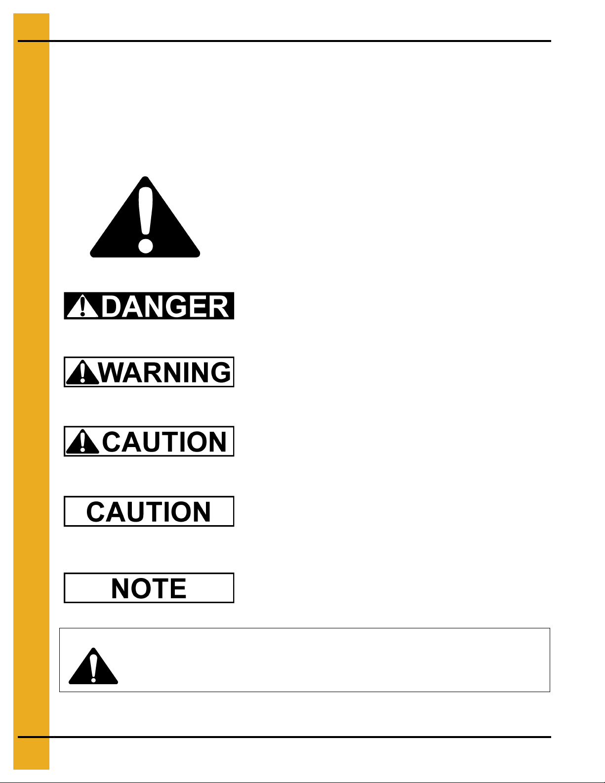
This is the safety alert symbol. It is used to alert you to
potential personal injury hazards. Obey all safety
messages that follow this symbol to avoid possible
injury or death.
DANGER indicates an imminently hazardous situation
which, if not avoided, will result in death or serious injury.
WARNING indicates a potentially hazardous situation
which, if not avoided, could result in death or serious injury.
CAUTION indicates a potentially hazardous situation which,
if not avoided, may result in minor or moderate injury.
CAUTION used without the safety alert symbol indicates a
potentially hazardous situation which, if not avoided, may
result in property damage.
NOTE indicates information about the equipment that you
should pay special attention.
WARNING! BE ALERT!
Personnel operating or working around electric fans should read this manual. This
manual must be delivered with the equipment to its owner. Failure to read this manual
and its safety instructions is a misuse of the equipment.
4 PNEG-1721 Peak Walk Around Assembly
Page 5

1. Safety
Safety Instructions
Our foremost concern is your safety and the safety of others associated with this equipment. We want
to keep you as a customer. This manual is to help you understand safe operating p rocedures and some
problems which may be encountered by the operator and other personnel.
As owner and/or operator, it is your responsibility to know what requirements, hazards and precautions
exist, and to inform all personnel associated with the equipment or in the area. Safety precautions may
be required from the personnel. Avoid any alterations to the equipment. Such alterations may produce
a very dangerous situation where SERIOUS INJURY or DEATH may occur.
PNEG-1721 Peak Walk Around Assembly 5
Page 6
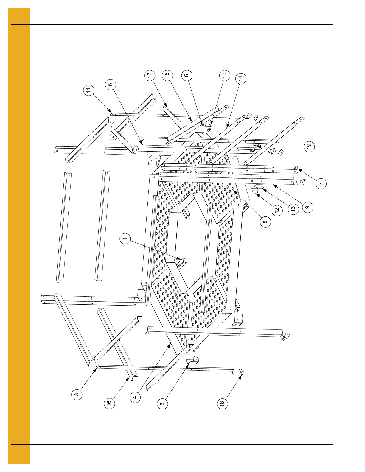
2. Parts List
Peak Walk Around Assembly (GT4-5061)
6 PNEG-1721 Peak Walk Around Assembly
Page 7

Peak Walk Around Assembly (GT4-5061) Parts List
Ref # Part # Description Qty
1 GT1-5133 Modular: Support, Horizontal Floor 6
2 GT1-5138 Modular: Bracket, Plank Connector 4
3 GT1-5136 Modular: Support, Vertical Roof Top Walk Around 4
4 GT1-5134 Plank, Roof Top Walk Around 5
5 GT1-5144 Modular: Bracket, Plank Connector 1
6 GT1-5141 Modular: Support, Vertical 30/30 Entry for Walk Around 1
7 GT1-5139 Modular: Support, Vertical for Transition 2
8 GT1-5135 Plank, Roof Top Entry Walk Around 1
9 GT1-5142 Modular: Support, Vertical 60/30 Entry for Walk Around 1
10 GT1-5143 Modular: Bracket, Plank Connector 1
11 GT1-5140 Modular: Support, Vertical 30/60 for Walk Around 1
12 GT1-5146 Modular: Bracket, Plank Connector, Entry 1
2. Parts List
13 GT1-5147 Modular: Bracket, Plank Connector, Entry 1
14 GT1-5131 Modular: Support, Transition 3
15 GT1-5132 Modular: Support, Transition 1
16 GT1-5137 Modular: Handrail, Roof Top Walk Around, Long 10
17 GT1-5145 Modular: Handrail, Roof Top Walk Around, Short 2
18 GT1-5130 Modular: Bracket, Roof Top Walk Around Support 7
19 GT3-0106 Latch, Hood Horizontal Mount SS 1
N/S S-396 Hex Nut 5/16"-18 YDP Grade 2 100
N/S S-4275 Bolt, HHTB 5/16"-18 x 3/4" ZN Grade 5 100
N/S S-2009 Screw, MS #10-24 x 5/8" OHP ZN Grade 2 2
N/S S-2010 Nylock Nut #10-24 ZN Grade 2 2
N/S S-8966 Bolt, HHCS 1/4"-20 x 2-1/4" ZN Grade 5 6
N/S S-7215 Flange Nut 1/4"-20 ZN 6
PNEG-1721 Peak Walk Around Assembly 7
Page 8

3. Assembly and Installation Instructions
Peak Walk Around Assembly Instructions (GT4-5061)
See detail C
on Page 9.
See Page 9 for assembly details.
See detail A
See detail B
on Page 9.
on Page 9.
Figure 3A
8 PNEG-1721 Peak Walk Around Assembly
Page 9

3. Assembly and Installation Instructions
Peak Walk Around Assembly Instructions (GT4-5061) (Continued)
Detail C
Detail A
Detail B
Figure 3B
PNEG-1721 Peak Walk Around Assembly 9
Page 10

3. Assembly and Installation Instructions
Peak Walk Around Assembly Instructions (GT4-5061) (Continued)
1. Begin assembling vertical handrail supports with horizontal handrail supports.
2. Assemble vertical handrail support (GT1-5139) with the other vertical handrail support (GT1-5141)
using 5/16" hardware such a way, that both the 3/16" holes align on each component.
(See Figure 3C.)
Figure 3C
3. Assemble vertical handrail support (GT1-5140), short horizontal handrail support (GT1-5145) using
5/16" hardware. (See Figure 3D.)
Figure 3D
10 PNEG-1721 Peak Walk Around Assembly
Page 11

3. Assembly and Installation Instructions
4. Assemble vertical handrail support (GT1-5136), horizontal handrail support (GT1-5137) using
5/16" hardware. (See Figure 3E.)
Figure 3E
5. Repeat the assembly Step 4 for three (3) times.
Figure 3F
PNEG-1721 Peak Walk Around Assembly 11
Page 12

3. Assembly and Installation Instructions
6. Assemble vertical support (GT1-5139) with vertical handrail support (GT1-5142). Assemble this
assembly, with horizontal handrail support (GT1-5137) using 5/16" hardware. (See Figure 3G.)
Figure 3G
7. Assemble catwalk entry plank (GT1-5135), brackets (GT1-5146, GT1-5147, GT1-5144, GT1-5143),
horizontal plank supports (GT1-5133) using 5/16" hardware.
(See Figure 3H below and Figure 3I on
Page 13.)
See detail A on
Page 13.
See detail B on
Page 13.
Figure 3H
12 PNEG-1721 Peak Walk Around Assembly
Page 13

3. Assembly and Installation Instructions
Detail BDetail A
Figure 3I
8. Assemble catwalk plank (GT1-5134), bracket (GT1-5138), horizontal plank support (GT1-5133)
using 5/16" hardware. (See Figure 3J.)
Figure 3J
PNEG-1721 Peak Walk Around Assembly 13
Page 14

3. Assembly and Installation Instructions
9. Repeat assembly Step 8 on Page 13 for four (4) times.
Figure 3K
10. Tighten all the hardware.
11. Assemble latch (GT3-0106) as shown using screws (S-2009) and nuts (S-2010). (See Figure 3L.)
Figure 3L
14 PNEG-1721 Peak Walk Around Assembly
Page 15

3. Assembly and Installation Instructions
Peak Walk Around Installation Instructions
1. Before installing the Peak Walk Around Assembly on the roof, assemble 7 ea. brackets (GT1-5130)
on the roof sheet at the third hole from outside of the roof as shown in Figure 3M.
Figure 3M
2. Install the Peak Walk Around Assembly on the roof such a way, the entry would align with the
ladder. (See Figure 3N.) Assemble transition supports (GT1-5131 and GT1-5132) using
5/16" hardware as shown in Figure 3N.
Figure 3N
PNEG-1721 Peak Walk Around Assembly 15
Page 16

3. Assembly and Installation Instructions
3. Fasten horizontal supports to the roof sheet using 1/4" hardware as shown in Figure 3O.
Figure 3O
16 PNEG-1721 Peak Walk Around Assembly
Page 17

4. Warranty
GSI Group, LLC Limited Warranty
The GSI Group, LLC (“GSI”) warrants products which it manufactures to be free of defects in materials and workmanship
under normal usage and conditions for a period of 12 months after sale to the original end-user or if a foreign sale,
14 months from arrival at port of discharge, whichever is earlier. The end-user’s sole remedy (and GSI’s only obligation)
is to repair or replace, at GSI’s option and expense, products that in GSI’s judgment, contain a material defect in materials
or workmanship. Expenses incurred by or on behalf of the end-user without prior written authorization from the GSI
Warranty Group shall be the sole responsibility of the end-user.
Warranty Extensions:
The Limited Warranty period is extended for the following products:
Product Warranty Period
Performer Series Direct Drive Fan Motor 3 Years
AP Fans and Flooring
Cumberland
Feeding/Watering
Systems
Grain Systems Grain Bin Structural Design 5 Years
Grain Systems
Farm Fans
Zimmerman
All Fiberglass Housings Lifetime
All Fiberglass Propellers Lifetime
Feeder System Pan Assemblies 5 Years **
Feed Tubes (1-3/4" and 2.00") 10 Years *
Centerless Augers 10 Years *
Watering Nipples 10 Years *
Portable and Tower Dryers 2 Years
Portable and Tower Dryer Frames and
Internal Infrastructure †
5 Years
* Warranty prorated from list price:
0 to 3 years - no cost to end-user
3 to 5 years - end-user pays 25%
5 to 7 years - end-user pays 50%
7 to 10 years - end-user pays 75%
** Warranty prorated from list price:
0 to 3 years - no cost to end-user
3 to 5 years - end-user pays 50%
† Motors, burner components
and moving parts not included.
Portable dryer screens included.
Tower dryer screens not included.
GSI further warrants that the portable and tower dryer frame and basket, excluding all auger and auger drive
components, shall be free from defects in materials for a period of time beginning on the twelfth (12
the date of purchase and continuing until the sixtieth (60
th
) month from the date of purchase (extended warranty period).
th
) month from
During the extended warranty period, GSI will replace the frame or basket components that prove to be defective
under normal conditions of use without charge, excluding the labor, transportation, and/or shipping costs incurred in
the performance of this extended warranty.
Conditions and Limitations:
THERE ARE NO WARRANTIES THAT EXTEND BEYOND THE LIMITED WARRANTY DESCRIPTION SET FORTH
ABOVE. SPECIFICALLY, GSI MAKES NO FURTHER WARRANTY OF ANY KIND, EXPRESS OR IMPLIED,
INCLUDING, WITHOUT LIMITATION, WARRANTIES OF MERCHANTABILITY OR FITNESS FOR A PARTICULAR
PURPOSE OR USE IN CONNECTION WITH: (I) PRODUCT MANUFACTURED OR SOLD BY GSI OR (II) ANY
ADVICE, INSTRUCTION, RECOMMENDATION OR SUGGESTION PROVIDED BY AN AGENT, REPRESENTATIVE
OR EMPLOYEE OF GSI REGARDING OR RELATED TO THE CONFIGURATION, INSTALLATION, LAYOUT,
SUITABILITY FOR A PARTICULAR PURPOSE, OR DESIGN OF SUCH PRODUCTS.
GSI shall not be liable for any direct, indirect, incidental or consequential damages, including, without limitation, loss of
anticipated profits or benefits. The sole and exclusive remedy is set forth in the Limited Warranty, which shall not exceed
the amount paid for the product purchased. This warranty is not transferable and applies only to the original end-user.
GSI shall have no obligation or responsibility for any representations or warranties made by or on behalf of any dealer,
agent or distributor.
GSI assumes no responsibility for claims resulting from construction defects or unauthorized modifications to products
which it manufactured. Modifications to products not specifically delineated in the manual accompanying the equipment
at initial sale will void the Limited Warranty.
This Limited Warranty shall not extend to products or parts which have been damaged by negligent use, misuse, alteration,
accident or which have been improperly/inadequately maintained. This Limited Warranty extends solely to products
manufactured by GSI.
Prior to installation, the end-user has the responsibility to comply with federal, state and local codes which apply to the
location and installation of products manufactured or sold by GSI.
9101239_1_CR_rev7.DOC (revised July 2009)
PNEG-1721 Peak Walk Around Assembly 17
Page 18

This equipment shall be installed in accordance with
the current installation codes and applicable
regulations which should be carefully followed in all
cases. Authorities having jurisdiction should be
consulted before installations are made.
Copyright © 2009 by GSI Group
Printed in the USA
GSI Group
1004 E. Illinois St.
Assumption, IL 62510-0020
Phone: 1-217-226-4421
Fax: 1-217-226-4420
www.gsiag.com
 Loading...