

Page 1

PNEG-1 71 7
CE Approved GSI/FFI Portable
Dryer Manual
Operation Manual
PNEG-1717
Date: 12-08-10
Page 2

Models:
1100 Se rie s (Models 1108, 1112, 1114, 1116, 1118, 1120, 1122, 1126, CFAB190, CFAB270, CFAB320,
CFAB370, CFAB400, CFAB460, CFAB510, CFAB511, CFAB601)
1200 Series (Models 1214, 1216, 1218, 1220, 1222, 1226, C2120A, C2122A, C2125A, C2130A,
C2132A, C2140A)
1200S Series (Models 1214S, 1218S, 1220S, 1222S, 1226S, CF2141, CF2181, CF500H,
CF2221, CF650M)
2300 Series (Models 2314, 2318, 2320, 2322, 2326, CF3142, CF3182, CF3202, CF3222, CF3262)
2400 Series (Models 2420, 2426, CF1000H, CF1300M)
3400 Series (Models 3414, 3418, 3420, 3422, 3426, CF4143, CF4183, CF4203, CF4223, CF4263)
3600 Series (Models 3620, 3626, CF1500H, CF2000M)
X-Stream Configuration - Uses same model numbers (and components) as listed above. The only
difference is that the fans are pointed in different directions.
2 PNEG-1717 CE Approved GSI/FFI Portable Dryer Manual
Page 3

Table of Contents
Contents
Chapter 1 Introduction ..........................................................................................................................................5
Dryer Operation ..................................................................................................................................... 5
Precautions ........................................................................................................................................... 5
Chapter 2 Safety .....................................................................................................................................................6
Safety Guidelines .................................................................................................................................. 6
Emergency Stop Switch ................................... ... ... ... .... ... ... ... .... ... ... ..................................................... 7
Chapter 3 Installation ............................................................................................................................................8
Transporting/Single Fan ................................... ... ... ... .......................................... .... ... ... ... ... .................. 8
Location of the Dryer ............................................................................................................................. 9
Foundation ............................................................................................................................................ 9
Supporting the Dryer ............................................................................................................................. 9
Anchor Points ........................................................................................................................................ 9
Wet/Dry Grain ....................................................................................................................................... 9
Electrical Power Supply ...................................................................................................................... 10
Fuel ..................................................................................................................................................... 11
Chapter 4 Specifications .....................................................................................................................................13
FFI Dimensions ................................................................................................................................... 13
FFI Specifications ................................................................................................................................ 15
GSI Dimensions .................................................................................................................................. 17
GSI Specifications ............................................................................................................................... 19
All Stack Dimensions .......................................................................................................................... 21
All Stack Specifications ....................................................................................................................... 24
Stack Dryer Foundation Specifications ............................................................................................... 28
Chapter 5 Vision Control Panel ..........................................................................................................................29
Vision Control Panel Layout ................................................................................................................ 29
Control Power Switch .......................................................................................................................... 29
Fan Switch .......................................................................................................................................... 29
Heater Switch ...................................................................................................................................... 30
Load Auger Switch .................................... ... .... ... ... ... .... ...................................... .... ... ... ... ................... 30
Unload Switch ..................................................................................................................................... 30
Outside Light Switch ........................................................................................................................... 30
Start Switch ......................................................................................................................................... 30
Stop Switch ......................................................................................................................................... 30
Chapter 6 Vision Touch Screen Display ........................ ... ... ... .... ... ....................................... ... ... .......................31
Boot Screen ........................................................................................................................................ 31
Chapter 7 Vision Test Firing .... ... ... .... .......................................... .......................................................................32
Dryer Pre-Season Checks .................................................................................................................. 32
Burner Test Fire .................................................................................................................................. 33
Dryer Shut Down ................................................................................................................................. 35
Emergency .......................................................................................................................................... 35
Chapter 8 Vision/Dri-Tek Dryer Operation .........................................................................................................36
Full Heat Drying ..................................................... ... .... ... ... ... ....................................... ...................... 36
Final Moisture ...................................................................................................................................... 36
Drying Temperatures .................................................... ... ... ... .... ... ... ... ... .... ... ... ... .... ... ......................... 36
Initial Setup Parameters ............................ ............................................. ............................................. 36
Timer and Delay Settings .................................................................................................................... 36
Setting the Temperatures ......................................................................................................
Start-Up .................................. ............................................. ................................................................ 36
Continuous Flow Drying Mode Using Regulation of Grain Temperature ............................................ 37
Continuous Flow Drying Mode Using Regulation of Moisture: 5 MR SP ............................................ 41
.............. 36
PNEG-1717 CE Approved GSI/FFI Portable Dryer Manual 3
Page 4

Table of Contents
Chapter 9 Vision Illustrations .............................................................................................................................44
Supply Line (LP Shown) ...................................................................................................................... 44
28" and 36" LP 1" NPT CE Pipe Train Assembly ................................................................................ 45
40" and 42" LP 1-1/2" NPT CE Pipe Train Assembly .......................................................................... 45
LP Vaporizer Coil Adjustment ............................................................................................................. 46
28" and 36" LP/NG 1" NPT CE Pipe Train Assembly ......................................................................... 47
Vision Fan/Heater Control Box ............................................................................................................ 49
Top Auger Drive .................................................................................................................................. 49
Discharge Safety Switch ..................................................................................................................... 50
Meter Roll Speed Sensor .................................................................................................................... 50
Vision Upper Control Box ........................ ... ......................................................................................... 51
Vision Control Panel (Rear) ................................................................................................................ 52
Vision Lower Control Box (Back Panel) .............................................................................................. 53
Chapter 10 Service ...............................................................................................................................................54
Seasonal Inspection/Service ............................................................................................................. 54
Lubrication Procedure ....................................................................................................................... 56
Fan Blade Removal and Installation .................................................................................................. 57
Fan Motor Removal and Installation ...................................... ............................................................ 57
Heater Parts Removal and Installation ............................ ... ... .... ... ... ... ... .... ... ... ... .... ... ... ... ... .... ... ........ 58
Metering Roll Servicing .......... ... ... .... ... ... ... ......................................................................................... 58
Main Controls ............................................................................ ... ... ... ... .... ... ..................................... 58
How to Clear a Jammed Meter Roll (All Power “OFF”) ...................................................................... 58
Chapter 11 Vision Schematics and Wiring Diagrams .................................... ... ... .... ... ... ...................................59
Fan/Heater Standard ......................................................................................................................... 59
Front Panel ........................................................................................................................................ 60
Upper Control Box ............................................................................................................................. 82
380-400 VAC 3 Phase ..................... ... ... ... ... .... ... ... ... .... ... ... .......................................... ..................... 83
Ladder Diagram ................................................................................................................................. 84
Chapter 12 Warranty ............................................................................................................................................87
4 PNEG-1717 CE Approved GSI/FFI Portable Dryer Manual
Page 5

1. Introduction
Keep the dryer clean.
Dryer Operation
Thank you for choosing a CE Approved GSI/FFI Vision Series Grain Dryers.
Please read this manual before installing or operating the equipment.
Make sure you and your employees understand all requirements, hazards and precautions associated
with this equipment. Failure to do so could result in SERIOUS INJURY or DEATH.
Ensure you have the correct power and fuel supply for the dryer.
Do not alter or modify this equipment.
Follow all local directives, codes and regulations when installing this equipment.
Authorities having jurisdiction should be consulted before installations are made.
Precautions
1. Keep ALL guards, safety decals and safety devices in place. NEVER operate with guards removed.
2. Restrict access to trained persons only.
3. NEVER bypass safety devices.
4. Switch OFF and LOCK all power and fuel before entering, servicing or accessing the equipment.
5. Follow all servicing instructions.
6. Keep the dryer CLEAN.
7. DO NOT exceed maximum temperatures or pressures.
8. Drying unclean grain will reduce the performance of the dryer and can cause fires.
9. CAUTION Equipment on the dryer can START AUTOMATICALLY.
10. Feed and discharge equipment must match dryer throughput.
11. DO NOT allow foreign material to be drawn into the fan.
12. When drying products not included in this manual refer to GSI for further precautions and instructions.
13. Check for leaks at least every day. Repair before operation.
Use Caution in the Operation of this Equipment
This dryer is designed and manufactured with operator sa fety in mind. However, residual hazards remain
due to the nature of grain drying. Use extreme caution at all times.
PNEG-1717 CE Approved GSI/FFI Portable Dryer Manual 5
Page 6
2. Safety
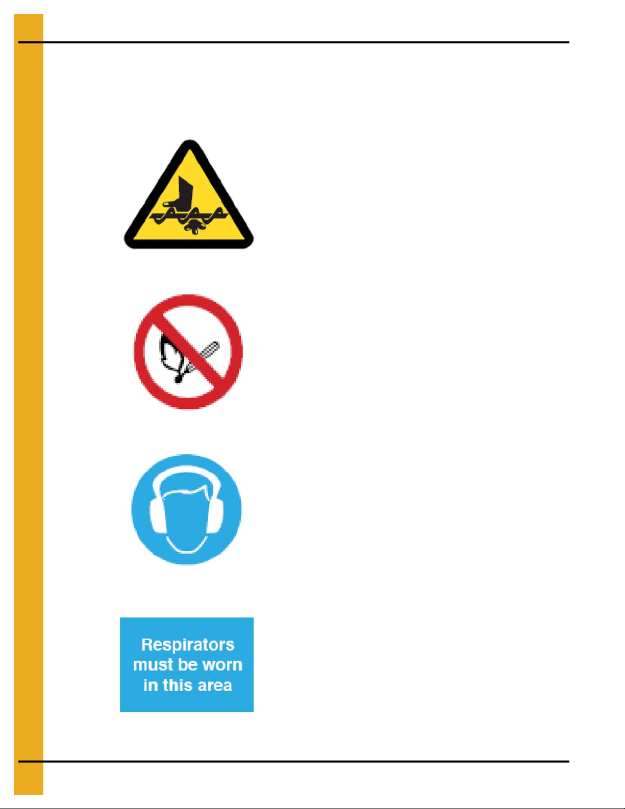
PROHIBITION
Example: No smoking or naked flames
MANDATORY ACTION
Example: Wear ear defenders
Instructions for your safety
HAZARD
Example: Rotating auger
Safety Guidelines
Please observe all safety decals on the equipment.
Safety decals on this equipment use the following system:
6 PNEG-1717 CE Approved GSI/FFI Portable Dryer Manual
Page 7
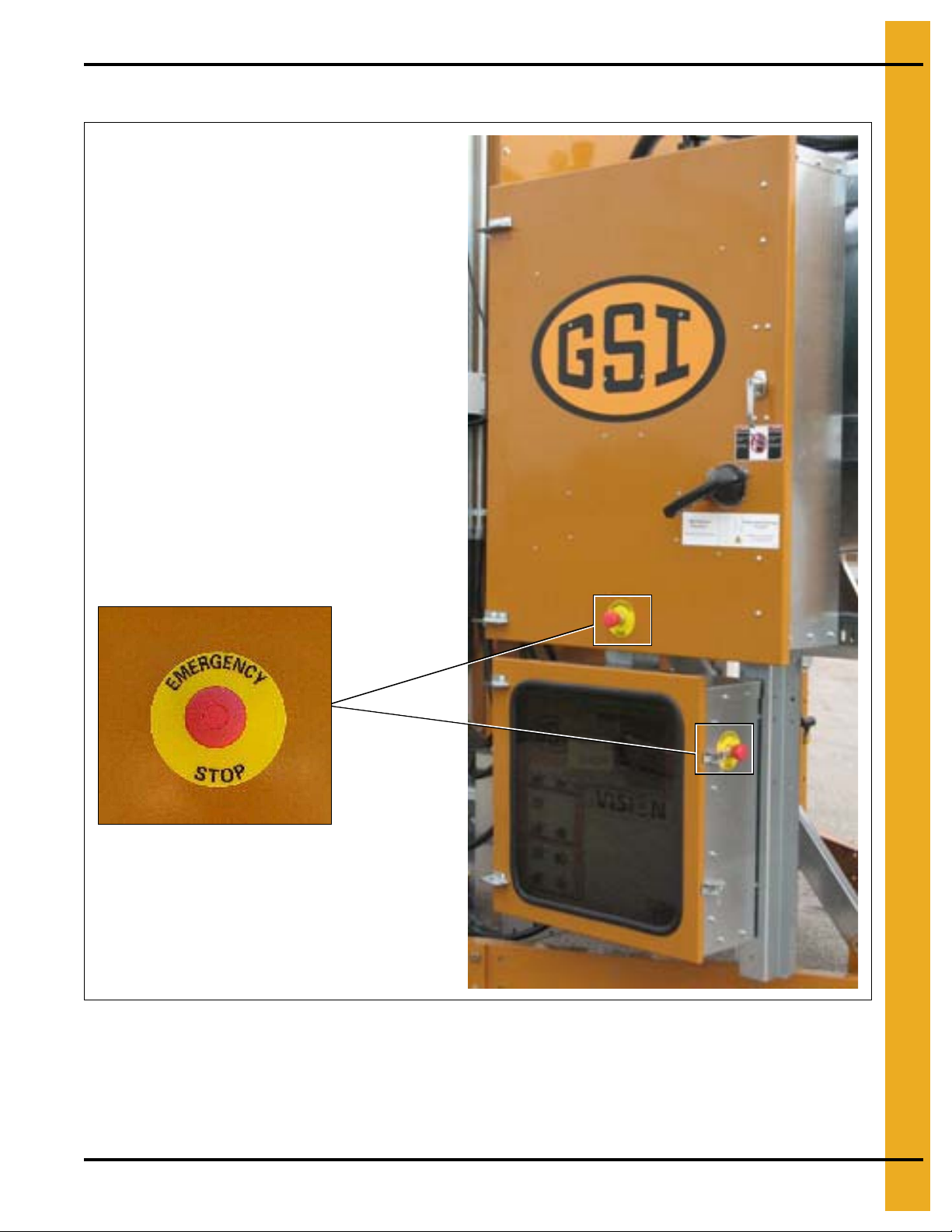
Emergency Stop Switch
2. Safety
In event of emergency press the Emergency Stop to stop all dryer equipment (power remains connected).
PNEG-1717 CE Approved GSI/FFI Portable Dryer Manual 7
Page 8
3. Installation
Washers
Locking nut
19 mm Minimum diameter
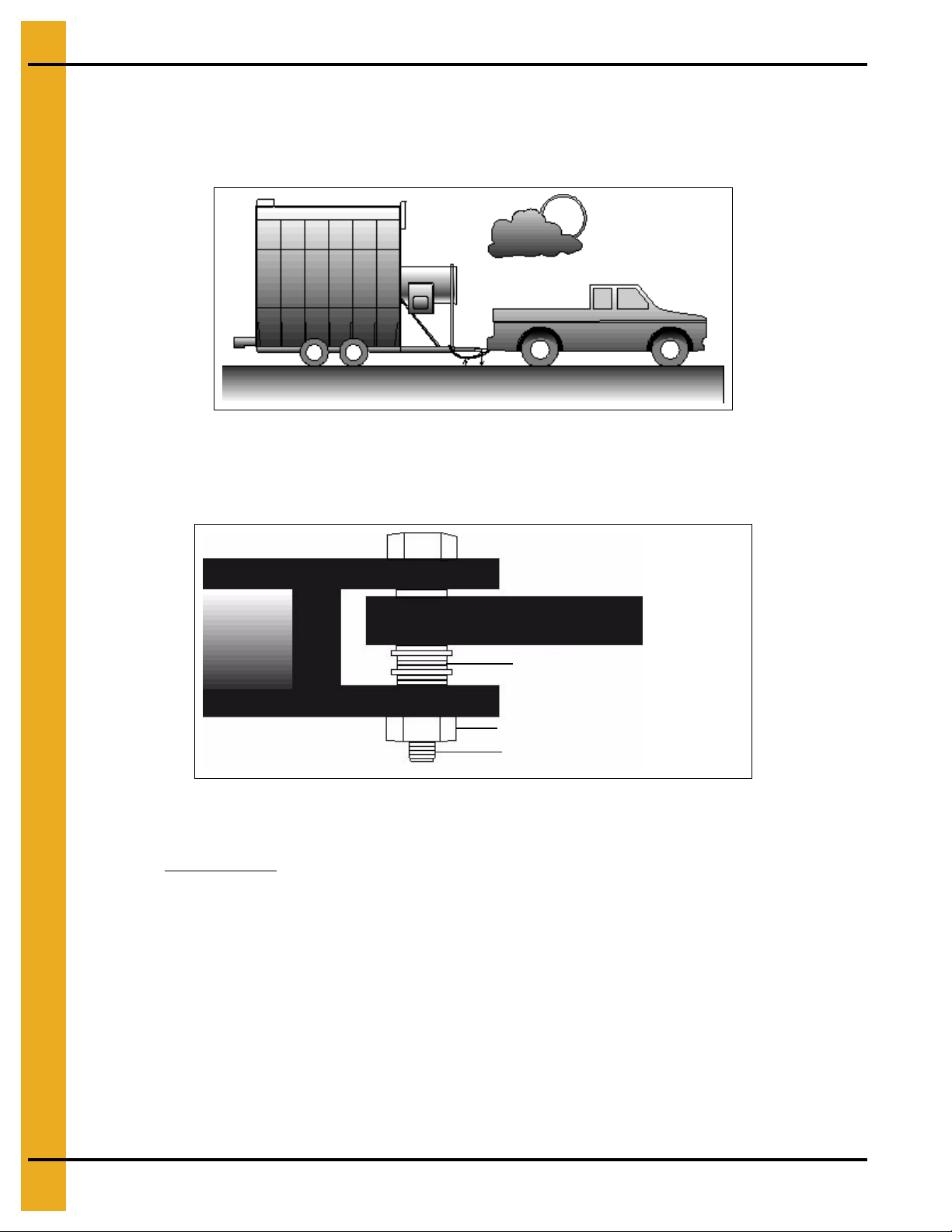
Transporting/Single Fan
When transporting the unit by truck or tractor observe these precautions:
1. Hitch height is 350 mm-430 mm. (See Figure 3A.)
Figure 3A
2. Hitch pin diameter is 19 mm minimum. Must be securely fastened. (See Figure 3B.)
3. Minimize hitch movement. (See Figure 3B.)
Figure 3B
4. Use a safety chain. (See Figure 3A.)
5. Dryer must be empty
and towed in accordance with all applicable laws and regulations.
6. Tyre pressure should be 3.8 bar.
7. Maximum towing speed is lowest of 70 km/h or statutory speed limit.
8. After first 80 km and every 300 km check:
a. Wheel bearing temperature <= 65°C.
b. Wheel nuts torque = 160 Nm.
8 PNEG-1717 CE Approved GSI/FFI Portable Dryer Manual
Page 9

Location of the Dryer
Consider:
1. Wet and dry storage.
2. Access to power and fuel.
3. Proximity to other structures (maintain minimum 1m clearance).
4. Noise.
5. Over head power.
Always install out of doors.
Foundation
1. Dryers should be installed on a suitable concrete base/foundation.
2. Foundation design to be carried out by qualified engineer.
3. Take into account ground and weather conditions.
3. Installation
4. Refer to dryer dimensions and loaded weights in table on Pages 11-25.
Supporting the Dryer
1. Wheels are for transport only.
2. Support under the hitch (drawbar removed).
3. Support every 2m on both sides.
4. Ensure the dryer is level in all directions.
5. Ensure supports can carry the full weight of the dryer.
6. Allow 400 mm clearance under the dryer for cleaning.
Anchor Points
Anchor to the concrete slab to ensure stability against high winds.
Wet/Dry Grain
Wet Grain Supply
1. Wet grain supply to the dryer intake may be gravity or powered auger/conveyor.
2. Powered fill equipment can be connected via the contactor provided in the dryer control box.
3. After the initial fill the system will run to maintain the dryer level.
4. Dryer fill is monitored by the out of grain timer. (Refer to PNEG-1710 for setting this timer.)
5. Dryer shuts down when out of grain.
PNEG-1717 CE Approved GSI/FFI Portable Dryer Manual 9
Page 10

3. Installation
Dry Grain Removal
1. Dry grain discharges at the rear of the dryer (front discharge optional).
2. Dry grain removal may be electrically connected to contactor provided in the main control box.
Electrical Power Supply
Ensure there is adequate electrical power to run the dryer. All supplies are 3 phase with neutral and
include a protective earth.
NOTE: Excessive voltage drops can cause equipment malfunction. Size supply and conductors to ensure
maximum 5% voltage drop under all start and run conditions.
Power Supply Disconnect
Supply connections are made at the main power disconnect on the upper control box.
Machine to Earth Grounding
1. The dryer must be connected to an adequate earth connection.
2. This must be carried out and tested in accordance with EU Directives, local regulations, codes and
EN60204 “Electrical Equipment of Machines”.
3. Failure to do so will result in equipment malfunction and can result in a dangerous fault condition.
4. Electrical supplies from generators must also include adequate, tested earth connection supplied by
the generator installer.
5. A 2.4m copper ground rod, supplied with the dryer must be installed in accordance with
local regulations.
Connecting Auxiliary Conveyors
Load and discharge conveyors connected into the dryer must not exceed electrical load information in
Specifications Chapter on Pages 15-25.
Motors exceeding these must be powered separate from the dryer with separate conta ctor a nd overloa d
device for each motor. Control may still be performed by the dryer.
10 PNEG-1717 CE Approved GSI/FFI Portable Dryer Manual
Page 11

3. Installation
Fuel
Liquid Propane (LP)
Liquid Draw
1. LPG is vaporized internally within the dryer.
2. LPG pipework and controls from the tank to the dryer must be installed by the gas supplier in
accordance with local directives, laws, codes and regulations.
3. LPG tank should be sized to supply the full heat input of all burners. See heater rating plates
for details.
Fuel System Specifications and Recommendations (LP) Liquid Propane
Dryer
Model #
1108/190 880 131 15 7.8
1112/270 1320 195 15 9.6
1114/320 1685 250 15 10.9
1116/370 1685 250 15 10.9
1118/400 2052 302 15 12.0
1120/460 2200 326 15 12.4
1122/511 2491 370 22 13.2
1126/601 2785 414 22 13.9
1214/2120 1700 250 22 (U)8.8 (L)6.8
1216 1993 294 22 (U)10.2 (L)6.8
1218/2125 1993 292 22 (U)10.2 (L)6.8
1220/2130 2565 382 22 (U)10.7 (L)7.8
1222 2931 434 22 (U)11.7 (L)7.8
1226/2140 3078 458 22 (U)12.2 (L)7.8
1214S/2141 2052 302 22 (U+L) 8.8
1218S/2181 2638 390 22 (U+L) 10.3
1220S/500H 3371 501 22 (U+L) 10.7
1222S/2221 4104 609 22 (U+L) 11.7
1226S/650M 4397 653 22 (U+L) 12.2
2314/3142 3445 510 22 T 10.7 B (U+L) 7.8
2318/3182 4104 609 22 T 11.7 B (U+L) 8.8
2320/3202 4837 717 22 T 12.2 B (U+L) 10.2
2322/3222 5130 760 22 T 13.7 B (U+L) 10.2
2326/3262 7183 1063 22 T 14.2 B (U+L) 11.2
2420/1000H 5277 784 22 (T+B, U+L) 10.2
2426/1300M 7622 1130 22 (T+B, U+L) 11.2
3414/4143 5130 760 22 T 10.8 M 10.8 B (U+L) 7.8
3418/4183 6156 911 22 T 11.7 M 11.7 B (U+L) 8.8
3420/4203 7036 1043 22 T 12.2 M 12.2 B (U+L) 10.2
3422/4223 7622 1130 22 T 13.7 M 13.7 B (U+L) 8.3
3426/4263 9381 1389 22 T 14.2 M 14.2 B (U+L) 11.2
3620/1500H 7915 1174 22 (T+M+B, U+L) 10.2
3626/2000M 11433 1646 22 (T+M+B, U+L) 11.2
* Maximum line size for 30m length. ** Maximum burner pressure 450 mBar.
Maximum Heat
Capacity kW
Maximum Fuel
Flow l/h
Fuel Line
Size mm *
Heater Orifice Diameter mm **
(U = Upper, L = Lower, Heater Position)
(T = Top, M = Middle, B = Base Dryer Module)
PNEG-1717 CE Approved GSI/FFI Portable Dryer Manual 11
Page 12
3. Installation
Natural Gas (N)
Gas Volume and Pressure
Natural gas supply should offer:
1. 49 MJ/m3 calorific value.
2. 650 mBar supply pressure. (Lower pressure may inhibit dryer performance.)
3. Gas pipework and controls from the supply to the dryer must be installed by the gas supplier in
accordance with local directives, laws, codes and regulations.
Check the supply capacity against dryer requirements. (See heater rating plates for details.)
Fuel System Specifications and Recommendations (NG) Natural Gas
Dryer
Model #
1108/190 880 82 32 9.7
1112/270 1320 123 38 11.9
1114/320 1685 157 38 13.3
1116/370 1685 157 38 13.2
1118/400 2052 188 50 14.1
1120/460 2200 206 50 14.9
1122/511 2491 233 50 15.3
1126/601 2785 261 50 16.5
1214/2120 1700 158 38 (U)10.5 (L)8.1
1216 1993 186 50 (U)12.9 (L)8.1
1218/2125 1993 186 50 (U)12.9 (L)8.1
1220/2130 2565 239 50 (U)13.3 (L)8.1
1222 2931 273 50 (U)13.3 (L)8.1
1226/2140 3078 287 50 (U)14.1 (L)8.1
1214S/2141 2052 191 38 (U+L) 10.5
1218S/2181 2638 246 38 (U+L) 12.9
1220S/500H 3371 314 50 (U+L) 13.3
1222S/2221 4104 316 50 (U+L) 14.1
1226S/650M 4397 410 50 (U+L) 14.9
2314/3142 3445 321 50 T 13.3 B (U+L) 9.7
2318/3182 4104 316 50 T 14.1 B (U+L) 10.5
2320/3202 4837 451 80 T 14.9 B (U+L) 12.9
2322/3222 5130 478 80 T 15.3 B (U+L) 12.9
2326/3262 7183 669 80 T 16.6 B (U+L) 13.7
2420/1000H 5277 492 80 (T+B, U+L) 12.9
2426/1300M 7622 710 80 (T+B, U+L) -13.7
3414/4143 5130 478 80 T 13.3 M 13.3 B (U+L) 9.7
3418/4183 6156 574 80 T 14.1 M 14.1 B (U+L) 10.5
3420/4203 7036 656 80 T 14.9 M 14.9 B (U+L) 12.9
3422/4223 7622 710 80 T 15.3 M 15.3 B (U+L) 12.9
3426/4263 9381 874 80 T 16.6 M 16.6 B (U+L) 13.7
3620/1500H 7915 738 80 (T+M+B, U+L) 12.9
3626/2000M 11433 1065 80 (T+<M+B, U+L) 13.7
* Maximum line size for a 100' distance. ** Maximum burner pressure 450 mBar.
Maximum Heat
Capacity kW
Maximum Fuel Flow
m3/h
Fuel Line Size
mm *
Heater Orifice Diameter mm **
(U = Upper, L = Lower, Heater Position)
(T = Top, M = Middle, B = Base Dryer Module)
12 PNEG-1717 CE Approved GSI/FFI Portable Dryer Manual
Page 13

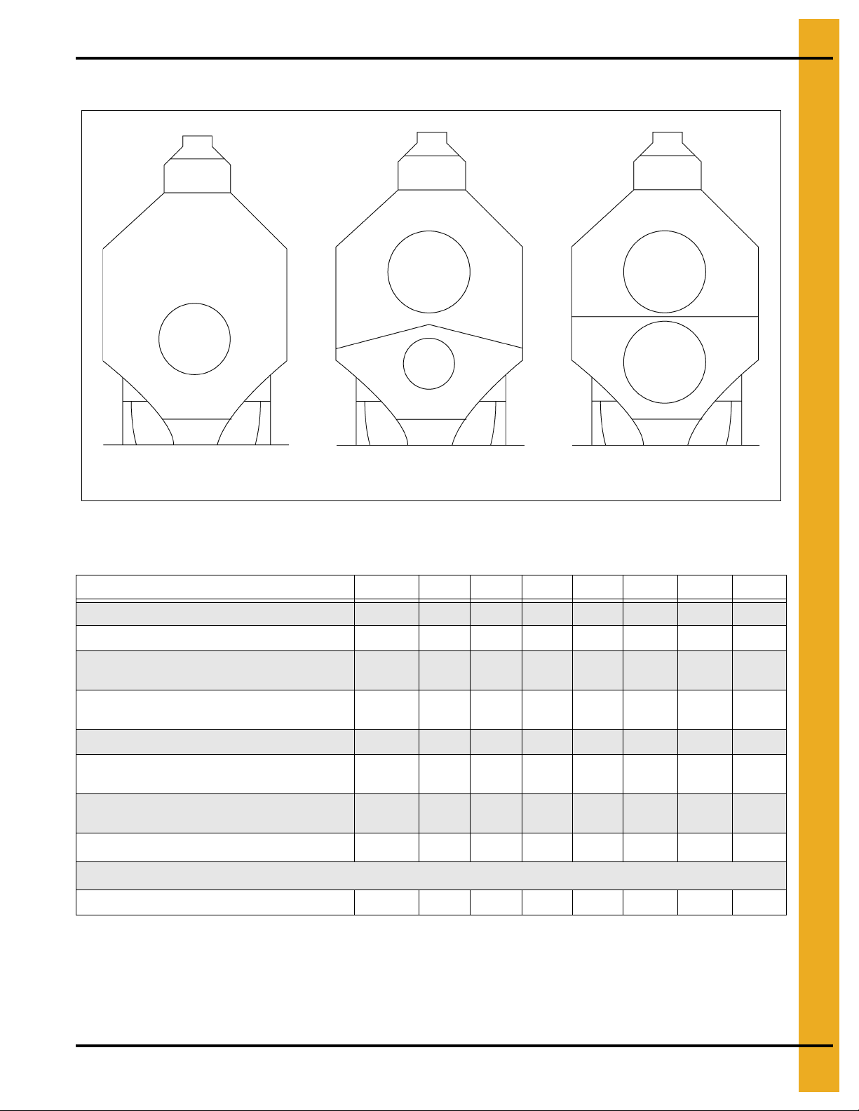
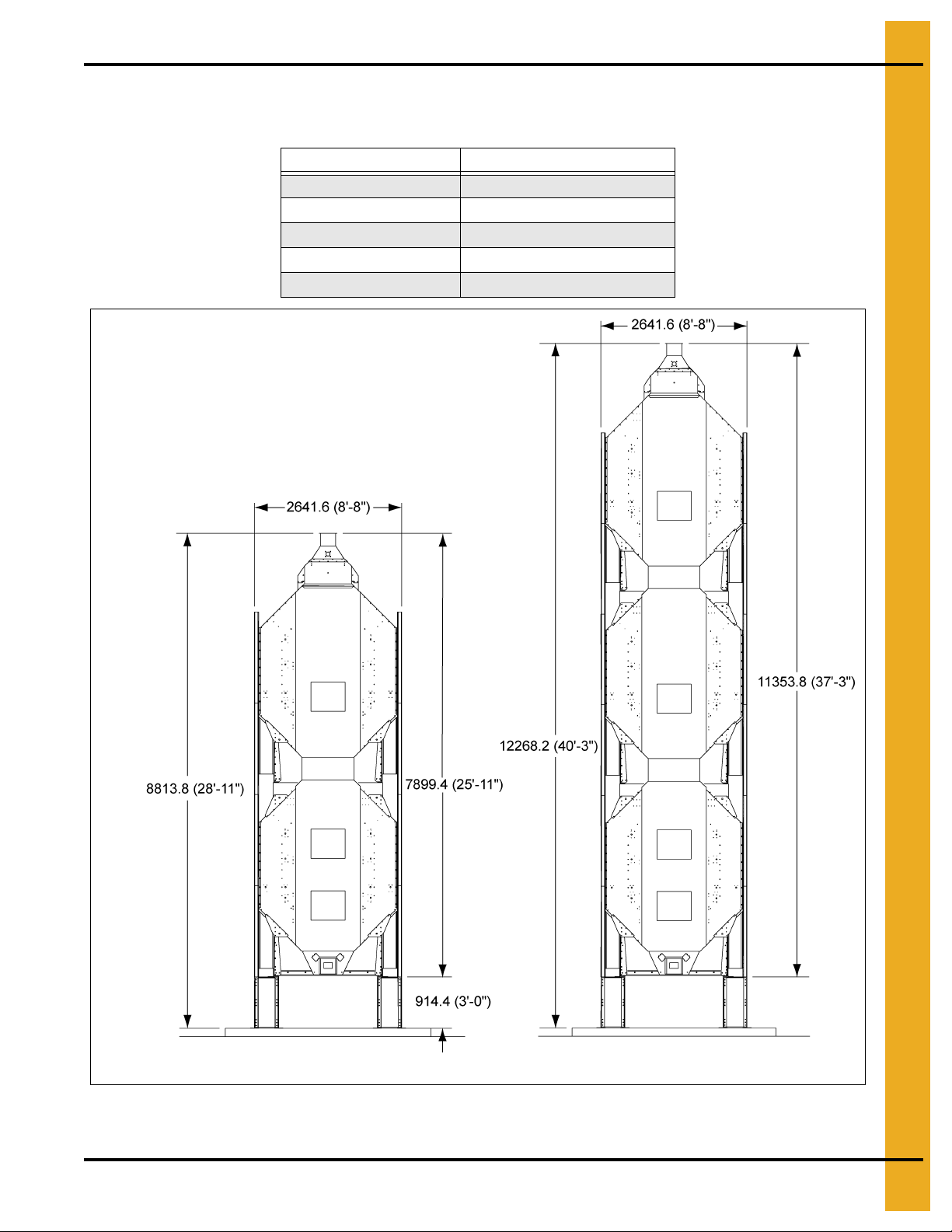
FFI Dimensions
4. Specifications
Figure 4A
Figure 4B
PNEG-1717 CE Approved GSI/FFI Portable Dryer Manual 13
Page 14
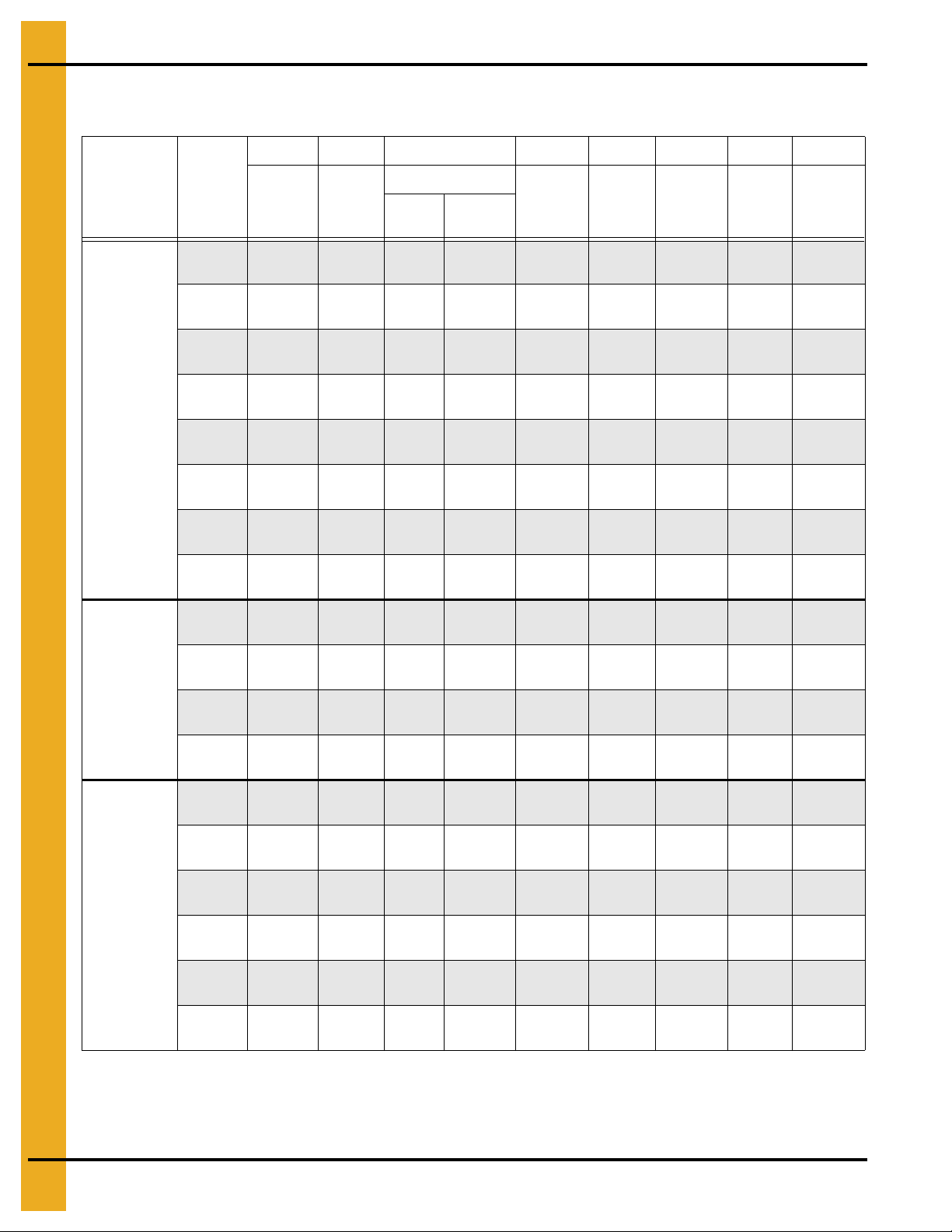
4. Specifications
Single Module FFI Transport and Installation Dimensions
Values are Valid for Transportation of Stack Modules
AB C DE FGH
1 Fan CFAB
Series Dryers
Dryer
Basket
190T (10')
270 (12')
320 (14')
370 (16')
400 (18')
460 (20')
511 (22')
601 (26')
320 (14')
Transport
Height
3632.2
(11' 11")
4089.4
(13' 5")
4089.4
(13' 5")
4089.4
(13' 5")
4089.4
(13' 5")
4089.4
(13' 5")
4089.4
(13' 5")
4089.4
(13' 5")
4089.4
(13' 5")
Installed
Width
2438.4
(8')
2438.4
(8')
2438.4
(8')
2438.4
(8')
2438.4
(8')
2438.4
(8')
2438.4
(8')
2438.4
(8')
2641.6
(8' 8")
Installed Height
Wet
Bin
3962.4
(13')
4419.6
(14' 6")
4419.6
(14' 6")
4419.6
(14' 6")
4419.6
(14' 6")
4419.6
(14' 6")
4419.6
(14' 6")
4419.6
(14' 6")
4419.6
(14' 6")
Standard
Top
3505.2
(11' 6")
3962.4
(13')
3962.4
(13')
3962.4
(13')
3962.4
(13')
3962.4
(13')
3962.4
(13')
3962.4
(13')
3962.4
(13')
Height w/o
Wet Bin
3124.2
(10' 3")
3581.4
(11' 9")
3581.4
(11' 9")
3581.4
(11' 9")
3581.4
(11' 9")
3581.4
(11' 9")
3581.4
(11' 9")
3581.4
(11' 9")
3581.4
(11' 9")
Frame
Width
1955.8
(6' 5")
1955.8
(6' 5")
1955.8
(6' 5")
1955.8
(6' 5")
1955.8
(6' 5")
1955.8
(6' 5")
1955.8
(6' 5")
1955.8
(6' 5")
1955.8
(6' 5")
Transport
Width
2438.4
(8')
2438.4
(8')
2438.4
(8')
2438.4
(8')
2438.4
(8')
2438.4
(8')
2438.4
(8')
2438.4
(8')
2438.4
(8')
Installed
Length
5232.4
(17' 2")
5842.0
(19' 2")
6451.6
(21' 2")
7061.2
(23' 2")
7670.8
(25' 2")
8280.4
(27' 2")
8890.0
(29' 2")
10109.2
(33' 2")
6451.6
(21' 2")
Transport
Length
5842.0
(19' 2")
6451.6
(21' 2")
7061.2
(23' 2")
7670.8
(25' 2")
8280.4
(27' 2")
8890.0
(29' 2")
9499.6
(31' 2")
10718.8
(35' 2")
7061.2
(23' 2")
2 Fan CFAB
410 (18')
Series Dryers
510 (22')
600 (26')
2120 (14')
2122 (16')
2125 (18')
C2100A
Series Dryers
2130 (20')
2132 (22')
2140 (26')
4089.4
(13' 5")
4089.4
(13' 5")
4089.4
(13' 5")
4089.4
(13' 5")
4089.4
(13' 5")
4089.4
(13' 5")
4089.4
(13' 5")
4089.4
(13' 5")
4089.4
(13' 5")
NOTE: All dimensions are in mm.
2641.6
(8' 8")
2641.6
(8' 8")
2641.6
(8' 8")
2438.4
(8')
2438.4
(8')
2438.4
(8')
2438.4
(8')
2438.4
(8')
2438.4
(8')
4419.6
(14' 6")
4419.6
(14' 6")
4419.6
(14' 6")
4419.6
(14' 6")
4419.6
(14' 6")
4419.6
(14' 6")
4419.6
(14' 6")
4419.6
(14' 6")
4419.6
(14' 6")
3962.4
(13')
3962.4
(13')
3962.4
(13')
3962.4
(13')
3962.4
(13')
3962.4
(13')
3962.4
(13')
3962.4
(13')
3962.4
(13')
3581.4
(11' 9")
3581.4
(11' 9")
3581.4
(11' 9")
3581.4
(11' 9")
3581.4
(11' 9")
3581.4
(11' 9")
3581.4
(11' 9")
3581.4
(11' 9")
3581.4
(11' 9")
1955.8
(6' 5")
1955.8
(6' 5")
1955.8
(6' 5")
1955.8
(6' 5")
1955.8
(6' 5")
1955.8
(6' 5")
1955.8
(6' 5")
1955.8
(6' 5")
1955.8
(6' 5")
2438.4
(8')
2438.4
(8')
2438.4
(8')
2438.4
(8')
2438.4
(8')
2438.4
(8')
2438.4
(8')
2438.4
(8')
2438.4
(8')
7670.8
(25' 2")
8890.0
(29' 2")
10109.2
(33' 2")
6451.6
(21' 2")
7061.2
(23' 2")
7670.8
(25' 2")
8280.4
(27' 2")
8890.0
(29' 2")
10109.2
(33' 2")
8280.4
(27' 2")
9499.6
(31' 2")
10718.8
(35' 2")
7061.2
(23' 2")
7670.8
(25' 2")
8280.4
(27' 2")
8890.0
(29' 2")
9499.6
(31' 2")
10718.8
(35' 2")
14 PNEG-1717 CE Approved GSI/FFI Portable Dryer Manual
Page 15

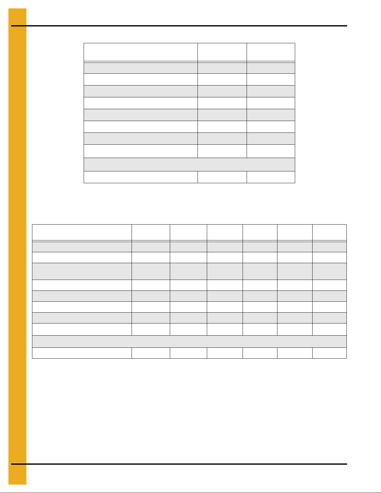
FFI Specifications
2 Fan CFAB profile
C2100A Profile
1 Fan CFAB profile
4. Specifications
Figure 4C
1 Fan CFAB Specifications
CFAB 150 8'CFAB 190
Total Holding Capacity (Bushels) 173 216 294 357 436 509 565 622 735
Grain Column Holding Capacity (Bushels) 149 186 257 300 376 414 460 506 598
Fans
Top Auger
Capacity (BPH) 680 925 1150 1800 2800 2800 2800 2800 2800
Bottom Auger
Meter Roll Drive
Capacity - Maximum Rate
Electrical Load (Fans, Top and Bottom Augers2)
380 Volt, 50 Hz, 3 Phase 23 30 30 32 40 46 61 69 91
1
Actual discharge rate is controlled by meter roll speed adjustment, at 5% to 100% of maximum rate.
2
Excludes auxiliary load and unlo ad conveyor equipment.
1
(BPH)
28"
10-13 HP
8" Dia.
1.5 HP
8" Dia.
1 HP
SCR,
3/4 HP
1120 1400 1680 1960 2240 2520 2800 3080 3640
10-13 HP
8" Dia.
2 HP
8" Dia.
1.5 HP
SCR,
3/4 HP
10'
28"
CFAB 270
12'
36 "
15 HP
8" Dia.
2 HP
8" Dia.
2 HP
SCR,
3/4 HP
CFAB 320
14'
40 "
15 HP
8" Dia.
5 HP
8" Dia.
3 HP
SCR,
3/4 HP
CFAB 370
16'
40 "
15 HP
8" Dia.
5 HP
8" Dia.
3 HP
SCR,
3/4 HP
CFAB 400
18'
42 "
20 HP
8" Dia.
5 HP
8" Dia.
3 HP
SCR,
3/4 HP
CFAB 460
20'
42 "
25 HP
8" Dia.
7.5 HP
8" Dia.
5 HP
SCR,
3/4 HP
CFAB 51 1
22'
42 "
30 HP
8" Dia.
7.5 HP
8" Dia.
5 HP
SCR,
3/4 HP
CFAB 601
40 HP
8" Dia.
10 HP
8" Dia.
7.5 HP
SCR,
3/4 HP
26'
42 "
PNEG-1717 CE Approved GSI/FFI Portable Dryer Manual 15
Page 16
4. Specifications
2 Fan CFAB Specifications
CFAB 510
22'
Total Holding Capacity (Bushels) 622 735
Grain Column Holding Capacity (Bushels) 506 598
Fans 36" 15 HP (2) 40" 20 HP (2)
Top Auger 8" Dia. 7.5 HP 8" Dia. 10 HP
Capacity (BPH) 2800 2800
Bottom Auger 8" Dia. 5 HP 8" Dia. 7.5 HP
Meter Roll Drive SCR, 3/4 HP SCR, 3/4 HP
Capacity - Maximum Rate
1
(BPH)
3080 3640
Electrical Load (Fans, Top and Bo ttom Augers2)
380 Volt, 50 Hz, 3 Phase 69 109
1
Actual discharge rate is controlled by meter roll speed adjustment, at 5% t o 100% of maximum rate.
2
Excludes auxiliary load and unl o ad conveyor equipment.
C2100A Specifications
CFAB 600
26'
C2120A
14'
Total Holding Capacity (Bushels) 375 436 490 544 599 708
Grain Column Holding Capacity (Bushels) 322 376 415 460 517 600
Fans
Top Auger 8" Dia. 5 HP 8" Dia. 5 HP 8" Dia. 5 HP 8" Dia. 7.5 HP 8" Dia. 7.5 HP 8" Dia. 10 HP
Capacity (BPH) 1800 2800 2800 2800 2800 2800
Bottom Auger 8" Dia. 3 HP 8" Dia. 3 HP 8" Dia. 3 HP 8" Dia. 5 HP 8" Dia. 5 HP 8" Dia. 7.5 HP
Meter Roll Drive SCR, 3/4 HP SCR, 3/4 HP SCR, 3/4 HP SCR, 3/4 HP SCR, 3/4 HP SCR, 3/4 HP
Capacity - Maximum Rate1 (BPH)
Electrical Load (Fans, Top and Bottom Augers2)
380 Volt, 50 Hz, 3 Phase 50 56 56 63 69 87
1
Actual discharge rate is controlled by meter ro ll sp ee d ad ju stment, at 5% to 100% of maximum rate.
2
Excludes auxiliary load and unl oad conveyor equipment.
28" 10-13 HP/
28" 10-13 HP
1960 2240 2520 2800 3080 3640
C2122A
16'
28" 10-13 HP/
36" 15 HP
C2125A
18'
28" 10-13 HP/
36" 15 HP
C2130A
20'
28" 10-13 HP/
40" 20 HP
C2132A
22'
28" 10-13 HP/
42" 20 HP
C2140A
26'
28" 10-13 HP/
42" 25 HP
16 PNEG-1717 CE Approved GSI/FFI Portable Dryer Manual
Page 17
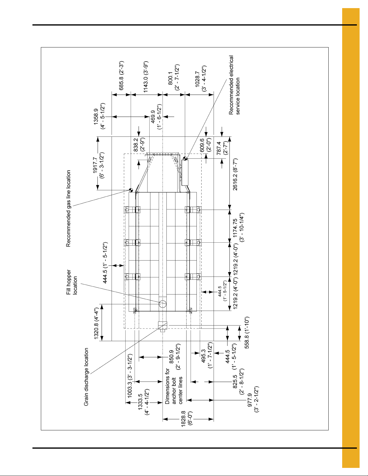
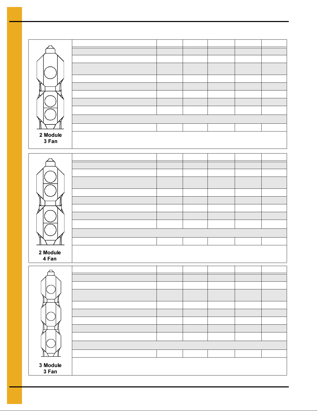
GSI Dimensions
4. Specifications
Figure 4D
Figure 4E
PNEG-1717 CE Approved GSI/FFI Portable Dryer Manual 17
Page 18
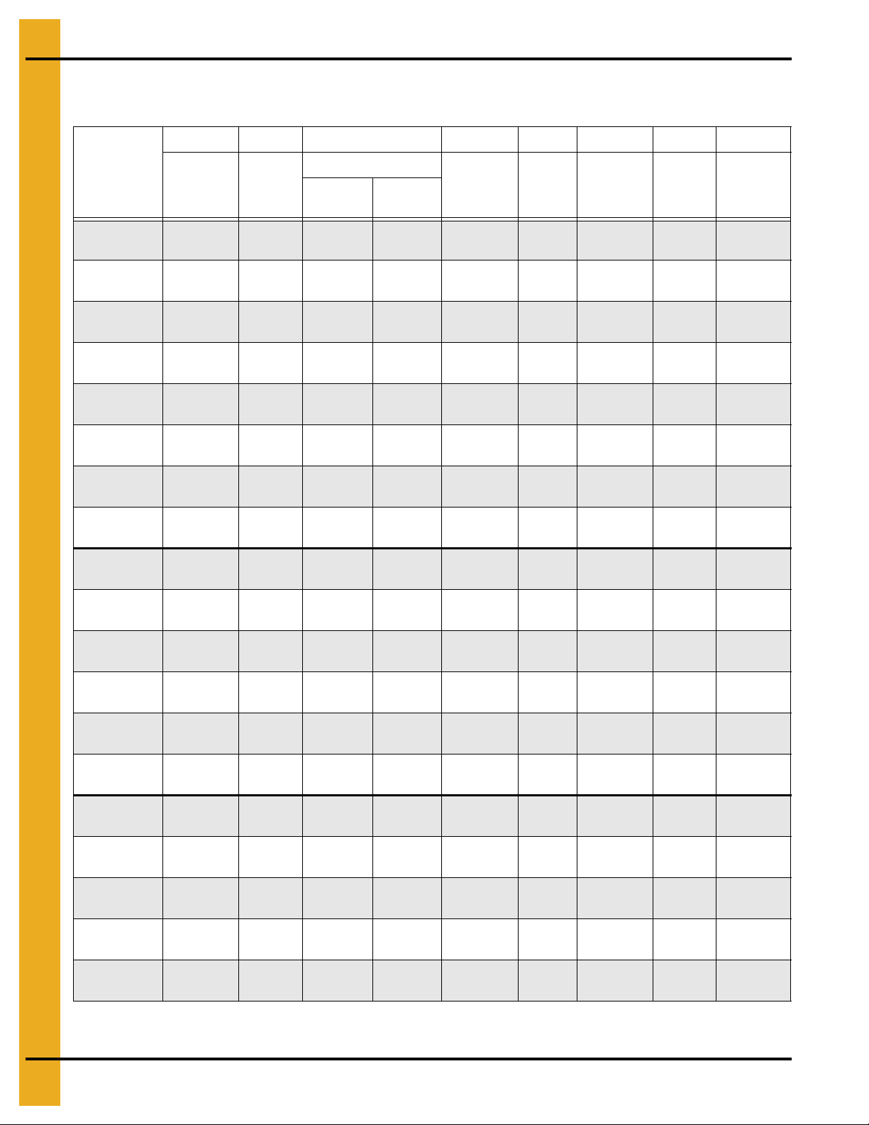
4. Specifications
AB C DEFGH
Single Module GSI Transport and Installation Dimensions
Values are Valid for Transportation of Stack Modules
Dryer
Basket
1108T
1112
1114
1116
1118
1120
1122
1126
1214
Transport
Height
4089.4
(13' 5'')
4089.4
(13' 5'')
4089.4
(13' 5'')
4089.4
(13' 5'')
4089.4
(13' 5'')
4089.4
(13' 5'')
4089.4
(13' 5'')
4089.4
(13' 5'')
4089.4
(13' 5'')
Installed
Width
2438.4
(8')
2438.4
(8')
2438.4
(8')
2438.4
(8')
2438.4
(8')
2438.4
(8')
2438.4
(8')
2438.4
(8')
2438.4
(8')
Installed Height
Wet
Bin
4419.6
(14' 6'')
4419.6
(14' 6'')
4419.6
(14' 6'')
4419.6
(14' 6'')
4419.6
(14' 6'')
4419.6
(14' 6'')
4419.6
(14' 6'')
4419.6
(14' 6'')
4419.6
(14' 6'')
Standard
3962.4
3962.4
3962.4
3962.4
3962.4
3962.4
3962.4
3962.4
3962.4
Top
(13')
(13')
(13')
(13')
(13')
(13')
(13')
(13')
(13')
Height w/o
Wet Bin
3581.4
(11' 9'')
3581.4
(11' 9'')
3581.4
(11' 9'')
3581.4
(11' 9'')
3581.4
(11' 9'')
3581.4
(11' 9'')
3581.4
(11' 9'')
3581.4
(11' 9'')
3581.4
(11' 9'')
Frame
Width
1955.8
(6' 5'')
1955.8
(6' 5'')
1955.8
(6' 5'')
1955.8
(6' 5'')
1955.8
(6' 5'')
1955.8
(6' 5'')
1955.8
(6' 5'')
1955.8
(6' 5'')
1955.8
(6' 5'')
Transport
Width
2438.4
(8')
2438.4
(8')
2438.4
(8')
2438.4
(8')
2438.4
(8')
2438.4
(8')
2438.4
(8')
2438.4
(8')
2438.4
(8')
Installed
Length
4622.8
(15' 2'')
5842.0
(19' 2'')
6451.6
(21' 2'')
7061.2
(23' 2'')
7670.8
(25' 2'')
8280.4
(27' 2'')
8890.0
(29' 2'')
10109.2
(33' 2'')
6451.6
(21' 2'')
Transport
Length
5232.4
(17' 2'')
6451.6
(21' 2'')
7061.2
(23' 2'')
7670.8
(25' 2'')
8280.4
(27' 2'')
8890.0
(29' 2'')
9499.6
(31' 2'')
10718.8
(35' 2'')
7061.2
(23' 2'')
1216
1218
1220
1222
1226
1214S
1218S
1220S
1222S
1226S
4089.4
(13' 5'')
4089.4
(13' 5'')
4089.4
(13' 5'')
4089.4
(13' 5'')
4089.4
(13' 5'')
4089.4
(13' 5'')
4089.4
(13' 5'')
4089.4
(13' 5'')
4089.4
(13' 5'')
4089.4
(13' 5'')
2438.4
(8')
2438.4
(8')
2438.4
(8')
2438.4
(8')
2438.4
(8')
2641.6
(8' 8'')
2641.6
(8' 8'')
2641.6
(8' 8'')
2641.6
(8' 8'')
2641.6
(8' 8'')
4419.6
(14' 6'')
4419.6
(14' 6'')
4419.6
(14' 6'')
4419.6
(14' 6'')
4419.6
(14' 6'')
4419.6
(14' 6'')
4419.6
(14' 6'')
4419.6
(14' 6'')
4419.6
(14' 6'')
4419.6
(14' 6'')
3962.4
(13')
3962.4
(13')
3962.4
(13')
3962.4
(13')
3962.4
(13')
3962.4
(13')
3962.4
(13')
3962.4
(13')
3962.4
(13')
3962.4
(13')
3581.4
(11' 9'')
3581.4
(11' 9'')
3581.4
(11' 9'')
3581.4
(11' 9'')
3581.4
(11' 9'')
3581.4
(11' 9'')
3581.4
(11' 9'')
3581.4
(11' 9'')
3581.4
(11' 9'')
3581.4
(11' 9'')
1955.8
(6' 5'')
1955.8
(6' 5'')
1955.8
(6' 5'')
1955.8
(6' 5'')
1955.8
(6' 5'')
1955.8
(6' 5'')
1955.8
(6' 5'')
1955.8
(6' 5'')
1955.8
(6' 5'')
1955.8
(6' 5'')
2438.4
(8')
2438.4
(8')
2438.4
(8')
2438.4
(8')
2438.4
(8')
2438.4
(8')
2438.4
(8')
2438.4
(8')
2438.4
(8')
2438.4
(8')
7061.2
(23' 2'')
7670.8
(25' 2'')
8280.4
(27' 2'')
8890.0
(29' 2'')
10109.2
(33' 2'')
6451.6
(21' 2'')
7670.8
(25' 2'')
8280.4
(27' 2'')
8890.0
(29' 2'')
10109.2
(33' 2'')
7670.8
(25' 2'')
8280.4
(27' 2'')
8890.0
(29' 2'')
9499.6
(31' 2'')
10718.8
(35' 2'')
7061.2
(23' 2'')
8280.4
(27' 2'')
8890.0
(29' 2'')
9499.6
(31' 2'')
10718.8
(35' 2'')
NOTE: All dimensions are in mm.
18 PNEG-1717 CE Approved GSI/FFI Portable Dryer Manual
Page 19
GSI Specifications
1200 Series profile
1200S Series profile
1100 Series profile
4. Specifications
Figure 4F
1100 Series Dryer Specifications
1108T 1112 1114 1116 1118 1120 1122 1126
Total Holding Capacity (Bushels) 190 327 381 436 490 544 599 708
Grain Column Holding Capacity (Bushels) 160 282 329 376 423 470 517 611
Fans
Top Auger
Capacity (BPH) 2900 2900 3800 3800 3800 3800 3800 3800
Bottom Auger
Meter Roll Drive
Capacity - Maximum Rate
Electrical Load (Fans, Top and Bottom Augers2)
3 Phase, 380 Volt 22 33 36 44 49 68 75 88
1
Actual discharge rate is controlled by meter roll speed adjustment, at 5% to 100% of maximum rate.
2
Excludes auxiliary load and unload conveyor equipment.
1
(BPH)
28''
10-13 HP
8'' Dia.
1-1/2 HP
8'' Dia.
1 HP
SCR,
3/4 HP
1120 1680 1960 2240 2520 2800 3080 3640
36''
15 HP
8'' Dia.
3 HP
8'' Dia.
1-1/2 HP
SCR,
3/4 HP
40''
15 HP
8'' Dia.
5 HP
8'' Dia.
3 HP
SCR,
3/4 HP
40''
15 HP
8'' Dia.
5 HP
8'' Dia.
5 HP
SCR,
3/4 HP
42''
20 HP
8'' Dia.
5 HP
8'' Dia.
5 HP
SCR,
3/4 HP
42''
25 HP
8'' Dia.
7-1/2 HP
8'' Dia.
7-1/2 HP
SCR,
3/4 HP
42''
30 HP
8'' Dia.
7-1/2 HP
8'' Dia.
7-1/2 HP
SCR,
3/4 HP
42''
40 HP
8'' Dia.
10 HP
8'' Dia.
10 HP
SCR,
3/4 HP
PNEG-1717 CE Approved GSI/FFI Portable Dryer Manual 19
Page 20
4. Specifications
1200 Series Dryer Specifications
1214 1216 1218 1220 1222 1226
Total Holding Capacity (Bushels) 381 436 490 544 599 708
Grain Column Holding
Capacity (Bushels)
Fans
Top Auger
Capacity (BPH) 3800 3800 3800 3800 3800 3800
Bottom Auger
Meter Roll Drive SCR, 3/4 HP SCR, 3/4 HP SCR, 3/4 HP SCR, 3/4 HP SCR, 3/4 HP SCR, 3/4 HP
Capacity - Maximum Rate
Electrical Load (Fans, Top and Bottom Augers2)
3 Phase, 380 Volt 50 61 61 70 75 90
1
Actual discharge rate is controlled by meter roll speed adjustment, at 5% to 100% of maximum rate.
2
Excludes auxiliary load and unload conveyor equipment.
1
(BPH)
329 376 423 470 517 611
26'' 10-13 HP
36'' 10-13 HP
8'' Dia.
5 HP
8'' Dia.
5 HP
1960 2240 2520 2800 3080 3640
26'' 10-13 HP
36'' 15 HP
8'' Dia.
5 HP
8'' Dia.
5 HP
26'' 10-13 HP
36'' 15 HP
8'' Dia.
5 HP
8'' Dia.
5 HP
28'' 10-13 HP
40" 15 HP
8'' Dia.
7-1/2 HP
8'' Dia.
7-1/2 HP
28'' 10-13 HP
42'' 20 HP
8'' Dia.
7-1/2 HP
8'' Dia.
7-1/2 HP
28'' 10-13 HP
42'' 25 HP
8'' Dia.
10 HP
8'' Dia.
10 HP
1200S Series Dryer Specifications
1214S 1218S 1220S 1222S 1226S
Total Holding Capacity (Bushels) 381 490 544 599 708
Grain Column Holding Capacity (Bushels) 329 423 470 517 611
Fans 28'' 10-13 HP (2) 36'' 10-13 HP (2) 36'' 15 HP (2) 36'' 15 HP (2) 40'' 25 HP (2)
Top Auger
Capacity (BPH) 3800 3800 3800 3800 3800
Bottom Auger
Meter Roll Drive SCR, 3/4 HP SCR, 3/4 HP SCR, 3/4 HP SCR, 3/4 HP SCR, 3/4 HP
Capacity - Maximum Rate
Electrical Load (Fans, Top and Bottom Augers2)
3 Phase, 380 Volt 50 50 80 80 115
1
Actual discharge rate is controlled by meter roll speed adjustment, at 5% to 100% of maximum rate.
2
Excludes auxiliary load and unload conveyor equipment.
1
(BPH)
8'' Dia.
5 HP
8'' Dia.
5 HP
1960 2520 2800 3080 3640
8'' Dia.
5 HP
8'' Dia.
5 HP
8'' Dia.
7-1/2 HP
8'' Dia.
7-1/2 HP
8'' Dia.
7-1/2 HP
8'' Dia.
7-1/2 HP
8'' Dia.
10 HP
8'' Dia.
10 HP
20 PNEG-1717 CE Approved GSI/FFI Portable Dryer Manual
Page 21
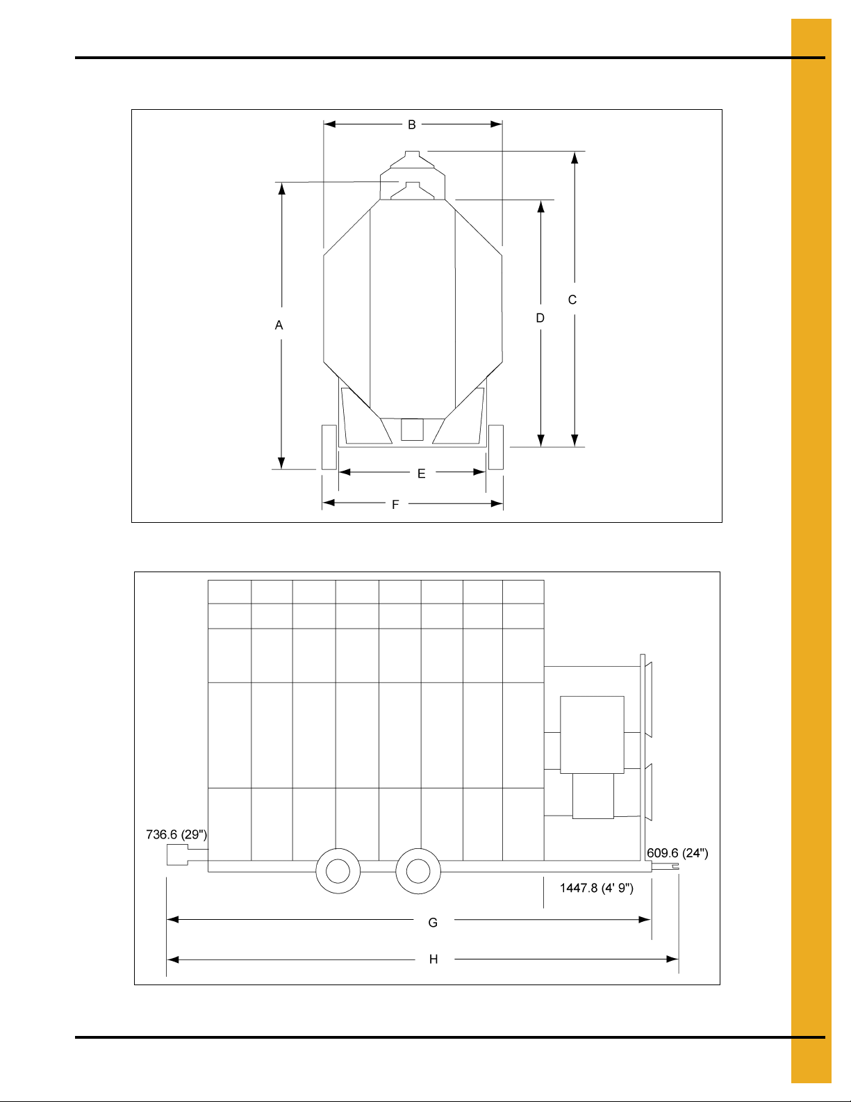
All Stack Dimensions
NOTE: All dimensions are in mm.
4. Specifications
Figure 4G Example of Stack Dryer Footprint
PNEG-1717 CE Approved GSI/FFI Portable Dryer Manual 21
Page 22
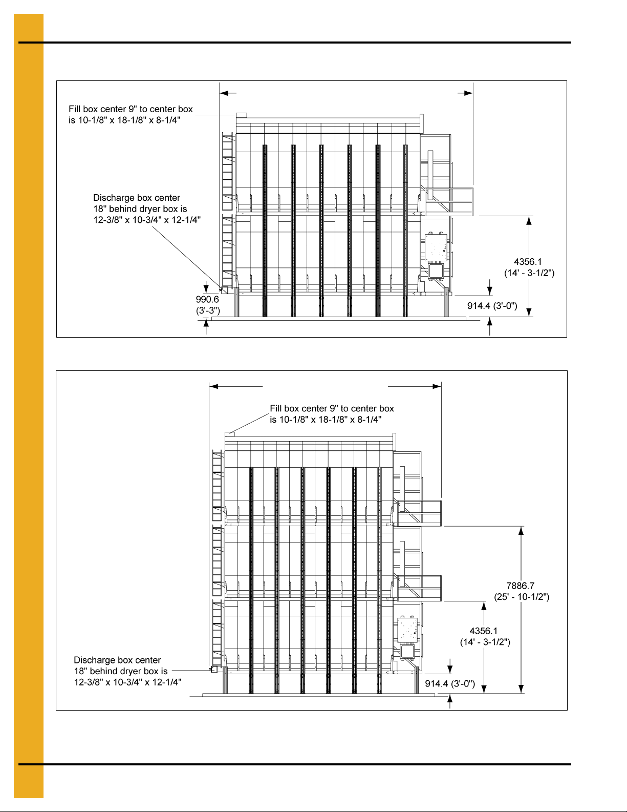
4. Specifications
“X” - Varies with dryer length (See Chart on Page 23.)
“X” - Varies with dryer length
(See Chart on Page 23.)
All Stack Dimensions (Continued)
Figure 4H Side View - 2 Module Stack Dryer
Figure 4I Stack Dryer Dimension (Side View - 3 Module Stack Dryer)
NOTE: All dimensions are in mm.
22 PNEG-1717 CE Approved GSI/FFI Portable Dryer Manual
Page 23
All Stack Dimensions (Continued)
End View - 2 Module Stack Dryer
End View - 3 Module Stack Dryer
Dryer Installed Length (1, 2 and 3 Module Stacks)
Basket Length Installed Length
14 7264.4 (23' 10")
18 8483.6 (27' 10")
20 9093.2 (29' 10")
22 9702.8 (31' 10")
26 10922.0 (35' 10")
4. Specifications
Figure 4J
NOTE: All dimensions are in mm.
PNEG-1717 CE Approved GSI/FFI Portable Dryer Manual 23
Page 24
4. Specifications
All Stack Specifications
Total Holding Capacity (Bushels) 731 940 1044 1149 1304
Grain Column Holding Capacity (Bushels) 679 873 970 1067 1261
Fans
Top Auger 8" Dia. 5 HP 8" Dia. 5 HP 8" Dia. 7.5 HP 8" Dia. 7.5 HP 8" Dia. 10 HP
Capacity (BPH) 3800 3800 3800 3800 3800
Bottom Auger 8" Dia. 5 HP 8" Dia. 5 HP 8" Dia. 7.5 HP 8" Dia. 7.5 HP 8" Dia. 10 HP
Meter Roll Drive SCR, 1/3 HP SCR, 1/3 HP SCR, 1/3 HP SCR, 1/3 HP SCR, 1/3 HP
Capacity - Maximum Rate
Electrical Load (Fans, Top and Bottom Augers2)
3 Phase, 380-400 Volt 61 66 91 96 141
1
Actual discharge rate is controlled by meter roll speed adjustment, at 5% to 100% of maximum rate.
2
Excludes auxiliary load and unload conveyor equipment.
Total Holding Capacity (Bushels) 731 940 1044 1149 1304
Grain Column Holding Capacity (Bushels) 679 873 970 1067 1261
Fans
Top Auger 8" Dia. 5 HP 8" Dia. 5 HP 8" Dia. 7.5 HP 8" Dia. 7.5 HP 8" Dia. 10 HP
Capacity (BPH) 3800 3800 3800 3800 3800
Bottom Auger 8" Dia. 5 HP 8" Dia. 5 HP 8" Dia. 7.5 HP 8" Dia. 7.5 HP 8" Dia. 10 HP
Meter Roll Drive SCR, 1/3 HP SCR, 1/3 HP SCR, 1/3 HP SCR, 1/3 HP SCR, 1/3 HP
Capacity - Maximum Rate
Electrical Load (Fans, Top and Bottom Augers2)
3 Phase, 380-400 Volt 69 69 98 98 154
1
Actual discharge rate is controlled by meter roll speed adjustment, at 5% to 100% of maximum rate.
2
Excludes auxiliary load and unload conveyor equipment.
1
1
(BPH)
(BPH)
14' 18' 20' 22' 26'
28" 10-13 HP
40" 15 HP
1960 2520 2800 3080 3640
14' 18' 20' 22' 26'
28" 10-13 HP
28" 10-13 HP
1960 2520 2800 3080 3640
36" 10-12 HP
42" 20 HP
36" 10-13 HP
36" 10-13 HP
36" 15 HP
42" 25 HP
36" 15 HP
36" 15 HP
36" 15 HP
42" 30 HP
36" 15 HP
36" 15 HP
40" 25 HP
42" 40 HP
40" 25 HP
40" 25 HP
14' 18' 20' 22' 26'
Total Holding Capacity (Bushels) 1074 1381 1534 1688 1995
Grain Column Holding Capacity (Bushels) 1022 1314 1460 1606 1898
Fans
Top Auger 8" Dia. 5 HP 8" Dia. 5 HP 8" Dia. 7.5 HP 8" Dia. 7.5 HP 8" Dia. 10 HP
Capacity (BPH) 3800 3800 3800 3800 3800
Bottom Auger 8" Dia. 5 HP 8" Dia. 5 HP 8" Dia. 7.5 HP 8" Dia. 7.5 HP 8" Dia. 10 HP
Meter Roll Drive SCR, 1/3 HP SCR, 1/3 HP SCR, 1/3 HP SCR, 1/3 HP SCR, 1/3 HP
1
Capacity - Maximum Rate
Electrical Load (Fans, Top and Bottom Augers2)
3 Phase, 380-400 Volt 72 88 116 131 179
1
Actual discharge rate is controlled by meter roll speed adjustment, at 5% to 100% of maximum rate.
2
Excludes auxiliary load and unload conveyor equipment.
(BPH)
40" 15 HP
40" 15 HP
1960 2520 2800 3080 3640
42" 20 HP
42" 20 HP
42" 25 HP
42" 25 HP
42" 30 HP
42" 30 HP
42" 40 HP
42" 40 HP
24 PNEG-1717 CE Approved GSI/FFI Portable Dryer Manual
Page 25
All Stack Specifications (Continued)
To tal Holding Capacity (Bushels) 1074 1381 1534 1688 1995
Grain Column Holding Capacity (Bushels) 1022 1314 1460 1606 1898
Fans
Top Auger 8" Dia. 5 HP 8" Dia. 5 HP 8" Dia. 7.5 HP 8" Dia. 7.5 HP 8" Dia. 10 HP
Capacity (BPH) 3800 3800 3800 3800 3800
Bottom Auger 8" Dia. 5 HP 8" Dia. 5 HP 8" Dia. 7.5 HP 8" Dia. 7.5 HP 8" Dia. 10 HP
Meter Roll Drive SCR, 1/3 HP SCR, 1/3 HP SCR, 1/3 HP SCR, 1/3 HP SCR, 1/3 HP
1
Capacity - Maximum Rate
Electrical Load (Fans, Top and Bottom Augers2)
3 Phase, 380-400 Volt 80 91 123 133 192
1
Actual discharge rate is controlled by meter roll speed adjustment, at 5% to 100% of maximum rate.
2
Excludes auxiliary load and unload conveyor equipment.
(BPH)
28" 10-13 HP
40" 15 HP
4. Specifications
14' 18' 20' 22' 26'
36" 10-13 HP
42" 20 HP
1960 2520 2800 3080 3640
36" 15 HP
42" 25 HP
36" 15 HP
42" 30 HP
40" 25 HP
42" 40 HP
14' 18' 20' 22' 26'
Total Holding Capacity (Bushels) 1074 1381 1534 1688 1995
Grain Column Holding Capacity (Bushels) 1022 1314 1460 1606 1898
Fans 28" 10-13 HP 36" 10-13 HP 36" 15 HP 36" 15 HP 40" 25 HP
To p Auger 8" Dia. 5 HP 8" Dia. 5 HP 8" Dia. 7.5 HP 8" Dia. 7.5 HP 8" Dia. 10 HP
Capacity (BPH) 3800 3800 3800 3800 3800
Bottom Auger 8" Dia. 5 HP 8" Dia. 5 HP 8" Dia. 7.5 HP 8" Dia. 7.5 HP 8" Dia. 10 HP
Meter Roll Drive SCR, 1/3 HP SCR, 1/3 HP SCR, 1/3 HP SCR, 1/3 HP SCR, 1/3 HP
Capacity - Maximum Rate1 (BPH)
1960 2520 2800 3080 3640
Electrical Load (Fans, Top and Bottom Augers2)
3 Phase, 380-400 Volt 97 97 137 137 218
1
Actual discharge rate is cont rolled by meter roll speed adjustment, at 5% to 100% of maximum rate.
2
Excludes auxiliary load and unload conveyor equipment.
PNEG-1717 CE Approved GSI/FFI Portable Dryer Manual 25
Page 26
4. Specifications
H
L
E
B
C
A
D
L
J
N
M
F
G
2362.2 (7'-9")-SAFETY
PLATFORM
3962.4 (13'-0")-OPTIONAL
CATWALK
4267.2 (14'-0")
812.8 (2'-8")-REAR SAFETY CAGE
SEE NOTE 3
SEE
NOTE 2
SEE
NOTE 1
All Stack Specifications (Continued)
Figure 4K
ABCD
14'
18'
20'
22'
26'
7048.5
(23'-1-1/2")
8267.7
(27'-1-1/2")
8877.3
(29'-1-1/2")
9486.9
(31'-1-1/2")
10706.1
(35'-1-1/2")
660.4
(2'-2")
660.4
(2'-2")
660.4
(2'-2")
660.4
(2'-2")
660.4
(2'-2")
4267.2
(14'-0")
5486.4
(18'-0")
6096.0
(20'-0")
6705.6
(22'-0")
7924.8
(26'-0")
1422.4
(4'-8")
1422.4
(4'-8")
1422.4
(4'-8")
1422.4
(4'-8")
1422.4
(4'-8")
NOTE: All dimensions are in mm.
1
E
406.4
(16" Min.)
406.4
(16" Min.)
406.4
(16" Min.)
406.4
(16" Min.)
406.4
(16" Min.)
FGHJ LMN
3403.6
(11'-2")
3403.6
(11'-2")
3403.6
(11'-2")
3403.6
(11'-2")
3403.6
(11'-2")
1466.85
(4'-9-3/4")
1466.85
(4'-9-3/4")
1466.85
(4'-9-3/4")
1466.85
(4'-9-3/4")
1466.85
(4'-9-3/4")
203.2
(0'-8")
203.2
(0'-8")
203.2
(0'-8")
203.2
(0'-8")
203.2
(0'-8")
2438.4
2438.4
2438.4
2438.4
2438.4
(8'-0")
(8'-0")
(8'-0")
(8'-0")
(8'-0")
(23'-9-1/2")
(23'-9-1/2")
(23'-9-1/2")
(23'-9-1/2")
(23'-9-1/2")
7251.7
7251.7
7251.7
7251.7
7251.7
3048.0
(10'-0")
3048.0
(10'-0")
3048.0
(10'-0")
3048.0
(10'-0")
3048.0
(10'-0")
1930.4
(6'-4")
1930.4
(6'-4")
1930.4
(6'-4")
1930.4
(6'-4")
1930.4
(6'-4")
1. A 12" thick reinforced concrete foundation and 16" pedestal (min.) are required. See bulletin
FL-02-2 for details. 32" Thick pedestal required for heat reclaimer option. (See bulletin FL-03-2
for details.)
2. Approximate location of standard service platform shown. See bulletin SP-02-2 for details.
For information on optional catwalk, see bulletin CATH-01-5.
3. For safety cage information, refer to bulletin SC-01-2.
26 PNEG-1717 CE Approved GSI/FFI Portable Dryer Manual
Page 27

All Stack Specifications (Continued)
H
L
E
B
C
A
D
L
J
K
N
F
G
4267.2 (14'-0")
812.8 (2'-8")-REAR SAFETY CAGE
SEE NOTE 3
2362.2 (7'-9")-SAFETY
PLATFORM
3962.4 (13'-0")-OPTIONAL
CATWALK
SEE
NOTE 2
SEE
NOTE 1
4. Specifications
Figure 4L
A BCD
14'
18'
20'
22'
26'
7048.5
(23'-1-1/2")
8267.7
(27'-1-1/2")
8877.3
(29'-1-1/2")
9486.9
(31'-1-1/2")
10706.1
(35'-1-1/2")
660.4
(2'-2")
660.4
(2'-2")
660.4
(2'-2")
660.4
(2'-2")
660.4
(2'-2")
4267.2
(14'-0")
5486.4
(18'-0")
6096.0
(20'-0")
6705.6
(22'-0")
7924.8
(26'-0")
1422.4
(4'-8")
1422.4
(4'-8")
1422.4
(4'-8")
1422.4
(4'-8")
1422.4
(4'-8")
1
E
406.4
(16" Min.)
406.4
(16" Min.)
406.4
(16" Min.)
406.4
(16" Min.)
406.4
(16" Min.)
FGHJKL N
3403.6
(11'-2")
3403.6
(11'-2")
3403.6
(11'-2")
3403.6
(11'-2")
3403.6
(11'-2")
1466.85
(4'-9-3/4")
1466.85
(4'-9-3/4")
1466.85
(4'-9-3/4")
1466.85
(4'-9-3/4")
1466.85
(4'-9-3/4")
203.2
(0'-8")
203.2
(0'-8")
203.2
(0'-8")
203.2
(0'-8")
203.2
(0'-8")
2438.4
(8'-0")
2438.4
(8'-0")
2438.4
(8'-0")
2438.4
(8'-0")
2438.4
(8'-0")
914.4
(3'-0")
914.4
(3'-0")
914.4
(3'-0")
914.4
(3'-0")
914.4
(3'-0")
7251.7
(23'-9-1/2")
7251.7
(23'-9-1/2")
7251.7
(23'-9-1/2")
7251.7
(23'-9-1/2")
7251.7
(23'-9-1/2")
1930.4
(6'-4")
1930.4
(6'-4")
1930.4
(6'-4")
1930.4
(6'-4")
1930.4
(6'-4")
NOTE: All dimensions are in mm.
1. A 12" thick reinforced concrete foundation and 16" pedestal (min.) are required. See bulletin
FL-02-2 for details. 32" Thick pedestal required for heat reclaimer option. (See bulletin FL-03-2
for details.)
2. Approximate location of standard service platform shown. See bulletin SP-02-2 for details.
For information on optional catwalk, see bulletin CATH-01-5.
3. For safety cage information, refer to bulletin SC-01-2.
PNEG-1717 CE Approved GSI/FFI Portable Dryer Manual 27
Page 28

4. Specifications
Stack Dryer Foundation Specifications
Stack Dryer Foundation
Basket Length 14 18 20 22 26
Concrete Pad Size (12' x “X”)
Concrete (Cubic Yards) (Cubic Meters)
#4 Rebar (Feet)
Anchors
1
2
3
3
10" (254 mm) Depth with 36" (914.4 mm) wide x 36" (914.4 mm) deep footings along each side.
#4 Reinforcing rods on 1' (304.8 mm)-0" centers. Both directions in slab and bottom of footing.
Use 3/4" (19.05 mm) x 9-5/8" (244.475 mm) minimum anchors with epoxy. GSI part #: Anchor (GTC-0003)
epoxy (GTC-0004).
2
(mm)
1
12' (3657.6) x
24' (7315.2)
20-3/4
(15.86451)
900'
(274320)
16 20 22 24 28
12' (3657.6) x
28' (8534.4)
24-1/4
(18.54046)
1060'
(323088)
12' (3657.6) x
30' (9144.0)
26
(19.87843)
1140'
(347472)
12' (3657.6) x
32' (9753.6)
27-1/2
(21.02526)
1220'
(371856)
Minimum soil bearing capacity = 2000 PSF.
Concrete specifications:
• Compressive strength at 28 days - 4000 PSI.
• Minimum cement content - 6 sacks/yard.
• Maximum slump - 4"±1".
12' (3657.6) x
36' (10972.8)
31
(23.7012)
1400'
(426720)
28 PNEG-1717 CE Approved GSI/FFI Portable Dryer Manual
Page 29

Vision Control Panel Layout
AUTO
AUTO
AUTO
AUTO
AUTO
(FANS RUN
EXCEPT DURING
BATCH UNLOAD)
(LES VENTILATEURS
FONCTIONNENT EXCEPTÉ
PENDANT UN
DÉCHARGEMENT DE LOT)
(FANS RUN
CONTINUOUSLY)
MARCHE
ON
MARCHE
ON
MARCHE
ON
MARCHE
ON
AUTO
MARCHE
ON
MARCHE
ON
(LES VENTILATEURS
FONCTIONNENT
CONTINUELLEMENT)
OFF
ARRÊT
OFF
ARRÊT
OFF
ARRÊT
OFF
ARRÊT
OFF
ARRÊT
OFF
ARRÊT
(HEATER “ON”
DURING BATCH DRY
CYCLE ONLY)
(RADIATEUR EN MARCHE
PENDANT LE CYCLE DE
SÉCHAGE SEULEMENT)
(HEATER “ON” WHEN
FAN RUNNING)
(RADIATEUR EN MARCHE
QUAND LE VENTILATEUR
FONCTIONNE)
(FANS RUN EXCEPT
DURING BATCH UNLOAD)
(LES VENTILATEURS
FONCTIONNENT EXCEPTÉ
PENDANT UN
DÉCHARGEMENT DE LOT)
(FANS RUN
CONTINUOUSLY)
(LES VENTILATEURS
FONCTIONNENT
CONTINUELLEMENT)
(HEATER “ON”
DURING BATCH DRY
CYCLE ONLY)
(HEATER “ON” WHEN FAN
RUNNING)
(RADIATEUR EN MARCHE
PENDANT LE CYCLE DE
SÉCHAGE SEULEMENT)
(RADIATEUR EN MARCHE
QUAND LE VENTILATEUR
FONCTIONNE)
TIMED SHUTDOWN
ARRÊT SYNCHRONISÉ
MANUAL
MANUEL
MANUAL
MANUEL
COMPUTER SELECTED
MODE
MODE SÉLECTIONNÉ
PAR L’ORDINATEUR
PRESS KNOB TO
ADJUST SPEED
APPUYEZ SUR LE BOUTON
POUR AJUSTER LA VITESSE
AUTO
OFF
ARRÊT
OFF
ARRÊT
START
DÉBUTER
STOP
ARRÊTER
2
1
FAN
VENTILATEUR
Fan switches
Heater switches
To uc h
screen
Load auger
switch
Unload auger
switch
Operator light
switch
Control power
switch
Stop switch
Start switch
Meter roll speed
FAN
VENTILATEUR
2
HEATER
BRÛLEUR
1
HEATER
BRÛLEUR
LOAD AUGER
CHARGER
LA FOREUSE
UNLOAD
AUGER
DÉCHARGER
LA FOREUSE
METER ROLL
SPEED
VITESSE DE
COMPTEUR
DE ROULEMENT
LIGHT
LUMIÈRE
POWER
COURANT
START
STOP
DÉBUTER
ARRÊTER
Lockout power
before servicing.
Will cause injury
or death.
HIGH VOLTAGE.
Fermez le courant
avant l’entretien.
Causera blessure
ou la mort.
HAUTE TENSION.
DC-1981
5. Vision Control Panel
Figure 5A
NOTE: Switches on this panel operate via software and MUST NOT be used as a service lock outs.
ISOLATE and LOCK OFF at the main disconnect when servicing.
Switches illuminate to indicate specific element is running.
Control Power Switch
Controls power to the Vision control system only.
NOTE: Does not disconnect the power to co mponents in the upper and lower control boxes. Use the main
Fan Switch
disconnect for this.
1. Selects/deselects each fan.
2. Bottom fan is always # 1.
3. ON (1) = Continuous fan.
4. AUTO (0/1) = Fan operates except during unload.
PNEG-1717 CE Approved GSI/FFI Portable Dryer Manual 29
Page 30

5. Vision Control Panel
Heater Switch
1. Selects/deselects each heater.
2. ON (1) = Burner operates with fan.
3. AUTO (0/1) = Burner operates in staged batch dry cycle only.
Load Auger Switch
1. Controls the fill system and auxiliary equipment where used.
2. In all modes the load auger operates when grain level is low.
3. AUTO (0/1) = Dryer shuts down after a preset period (out of grain timer) when incoming grain flow
ceases to the dryer. Timer disabled in MANUAL.
Unload Switch
1. Operates the unload system and auxiliary equipment where used.
2. MANUAL (1) = Metering rolls run in single speed only.
3. AUTO (0/1) = Metering rolls in variable speed mode (moisture control).
Outside Light Switch
1. AUTO (0/1) = Light OFF when dryer shuts down.
Start Switch
1. Starts the dryer subject to other switch settings.
Stop Switch
1. Stops all dryer functions.
2. Resets control following fault related shut down.
30 PNEG-1717 CE Approved GSI/FFI Portable Dryer Manual
Page 31

6. Vision Touch Screen Display
Buttons used to
update software. (See
PNEG-1506 Vision
programming manual.)
Boot Screen
1. With the Power switch ON, pushing the START initiates the Vision computer.
2. The boot screen has four (4) “buttons”. (See Figure 6A.)
3. The Start Dryer button enters the Default Operation screen.
Figure 6A
NOTE: See PNEG-1456 for vision touch screen display details.
PNEG-1717 CE Approved GSI/FFI Portable Dryer Manual 31
Page 32

7. Vision Test Firing
Ensure all safety shields are fitted, all doors are closed, and all personnel are
clear of the dryer before starting dryer.
Fix gas leaks immediately.
Dryer Pre-Season Checks
1. Perform these checks at the start of each season.
2. If any checks fail, consult your dealer.
3. Do not use the dryer unless checks are successful.
1. Inspect metering roll compartments for foreign objects which may cause damage.
2. Ensure that all switches on the dryer control panel are OFF.
3. Turn ON the electrical power supply to the dryer.
4. Switch Control Power to ON.
5. At the Boot screen press Start Dryer. The dryer check safety circuits. Any fault will be displayed and
must be rectified. If circuit checks are successful Start switch will illuminate.
6. Push the Dryer Start switch. Selector switches will be activated.
7. Open the main fuel supply on NG, adjust main regulator to minimum. Open main valve and set
pressure on supply line to 50 KPa and the shut off valves on the dryer.
8. Check for gas leaks.
9. With grain supply shut off, check correct rotation of the load auger. (Clockwise from drive end;
counterclockwise for front load dryers.)
10. Set Load Auger to AUTO position. After 8 minute the dryer should shut down and indicate an out of
grain error. Press Stop to reset. Press Start to re-start.
11. Set Unload switch to AUTO. Set (push then turn) metering rolls to 500 and press ACCEPT/EXIT.
Check bottom auger for counterclockwise rotation (at drive end). The meter roll motor should
rotate clockwise as viewed from the drive end of the gearbox. Auxiliary unload equipment should
also operate.
12. Set Unload switch to MANUAL. Set metering roll to 500 and press ACCEPT/EXIT. The botto m auger,
metering rolls and unload equipment should operate correctly.
13. CE Dryers have 7" metering rolls. Check metering roll speed of 4.3 RPM when roll speed is
1000 (maximum).
14. Ensure drive chain tension correct and all sections of the meter rolls rotate.
15. Turn the Unload switch OFF. The bottom auger will run for 60 seconds to allow for clean out.
32 PNEG-1717 CE Approved GSI/FFI Portable Dryer Manual
Page 33

7. Vision Test Firing
Dryer Pre-Season Checks (Continued)
16. Confirm that the meter roll control increases and decreases speed.
NOTE: Brushes inside the DC meter roll motor to become corrod ed after a period of no use, causing
a roll malfunction. This may be fixed by tapping the motor with a rubber mallet. Subsequent
operation should be normal.
17. Check fan rotation (counterclockwise) and reverse if required. (Swap any 2 phases on the fan
power supply.)
18. Check the burner safety function. Turn OFF the main gas valve. With the fans ON, turn the Heater
ON. The dryer should shut down after 20 seconds and “Ignition Failure Fan #” will appear. Reset the
dryer and repeat for each fan/heater.
Burner Test Fire
Repeat the following for each fan/heater:
1. The dryer must be full of grain, or the Air switch disabled. (SETUP > DIAGNOSTICS > DISABLE
TESTING > Yes > EXIT) After 5 minute, air switches will return to normal and cannot be disabled
again until the dryer has been re-started.
2. Test fire each burner. Turn the Burner switch to ON. The burner should ignite after a 10 seconds
purge delay.
3. Gas pressure should be shown on the gauge.
4. Adjust the plenum set point to 90°C (Temp > Plenum 1 Temp > 90 > Accept). Burner should be
in High-Fire.
5. Set gas pressure at regulator (use ball valve on NG).
6. Drop plenum set point until burner goes to Low-Fire.
7. Set Low-Fire pressure using needle valve screw on cycle valve. Burner should cycle between high
and low 1-3 times per minute.
8. If the burner does not cycle to Low-Fire, increase the regulator setting.
9. If the burner does not cycle to High-Fire, decrease gas pressure cycle valve.
10. If the flame pops or flutters, the pressure is too low. This can damage the burner. Increase pressure
to eliminate.
Approximate setting should be:
LP Gas Natural Gas
High-Fire 450 mBar High-Fire 450 mBar
Low-Fire 70-220 mBar Low-Fire 70-220 mBar
PNEG-1717 CE Approved GSI/FFI Portable Dryer Manual 33
Page 34

7. Vision Test Firing
Watch gauge for pressure
Throughput adjuster
Low-Fire needle valve
Pressure regulator
(High-Fire)
High pressure switch
Watch gauge for pressure
Supply line ball valve
Regulator
Figure 7A NG Pipe Train
Figure 7B NG Supply Pipe Train
34 PNEG-1717 CE Approved GSI/FFI Portable Dryer Manual
Page 35

Dryer Shut Down
To shut down the dryer,
1. Close the fuel supply valve.
2. Let the dryer run out of fuel.
3. Press the Dryer Stop button.
4. Turn OFF the control power.
5. Turn OFF the dryer safety disconnect and turn OFF the main power to the dryer.
Emergency
In case of emergency, push the Emergency Stop button.
7. Vision Test Firing
PNEG-1717 CE Approved GSI/FFI Portable Dryer Manual 35
Page 36

8. Vision/Dri-Tek Dryer Operation
Full Heat Drying
Full heat drying discharges hot grain. This yields higher drying capacity, but requires cooling elsewhere.
Final Moisture
Cooling will remove up to 3% additional moisture. The target moisture should be increased to allow for this
to prevent over drying.
Drying Temperatures
Recommended temperatures are as follow:
Product Top Fan Bottom Fan
Shelled Corn 110°C 84°C
Soybeans 54°C 54°C
Wheat, Barley, Milo, Oats 66°C 66°C
Drying efficiency is maximized by using highest possible temperatures, subject to avoiding product
damage/quality losses.
Dryer shut down, if still full, should be preceded by cooling for 10-15 minute to prevent water vapor
condensation and freezing in low temperatures.
Initial Setup Parameters
Power-up the dryer and press Start Dryer on the touch screen.
Timer and Delay Settings
To set the timers, touch the button at the bottom of Operation screen. The Select Timers to Modify
screen will appear. Refer to PNEG-1710 for instructions to set the timer and delays.
Setting the Temperatures
Press button on the Operation screen. Follow screen instructions to set plenum temperatures.
Start-Up
Follow pre-season checks in Service Chapter on Page 54.
Drying mode options are:
1. Regulation of Grain Temperature on Page 37.
2. Regulation of Moisture: 5 MR SP on Page 41.
3. Regulation of Moisture: Variable MR SP (not recommended for single module dryers).
36 PNEG-1717 CE Approved GSI/FFI Portable Dryer Manual
Page 37

8. Vision/Dri-Tek Dryer Operation
Continuous Flow Drying Mode Using Regulation of
Grain Temperature
Full Heat Continuous Flow Operation
In this example incoming grain 25% and target is 15% moisture.
1. Set continuous flow drying. SETUP > DRYING MODE > CONTINUOUS FLOW > ACCEPT/EXIT.
2. Set drying mode. M/C SETUP > REGULATION OF GRAIN TEMPERATURE > ACCEPT/EXIT > EXIT.
Figure 8A
3. Ensure the Unload switch is OFF (0).
4. Ensure fuel supply is on at all shut off valves.
5. Fill the dryer with grain. Load auger = AUTO (0/1).
6. Switch all fans switch ON (1).
7. Start each burner. Heater = ON (1).
8. Set plenum temperatures to 80°C.
9. Refer to PNEG-1650/PNEG-1651 for the full heat settings for the dryer. Note the drying time and
speed settings for the drying requirements.
10. Run the fans and burners for the drying time +10%. Example: 10% Removal = 54 Minute so run
fans/heaters for 54+5.4 = 59-60.
11. After the required time set unload auger to MANUAL (1).
12. Set the meter roll speed, (manual speed) to the “1 Speed setting” noted from the drying chart. Press
Accept/Exit button to set this value into the computer. Grain should begin to run.
13. Run again for 10% longer than the drying time noted from the chart. This will even out, but over dry
the grain in the dryer.
PNEG-1717 CE Approved GSI/FFI Portable Dryer Manual 37
Page 38

8. Vision/Dri-Tek Dryer Operation
Figure 8B
14. Set the plenums 15°C to 30°C apart. Warmest at the top.
15. DO NOT ADJUST THE DRYER FOR MOISTURE DURING THIS PROCESS. THIS WILL CAUSE
CONTROL INSTABILITY.
16. After the run time in Step 13 on Page 37, set the moisture control. Unload switch = AUTO.
17. Push the meter roll adjustment knob. Ensure 2 Speed is selected.
18. Set the high and low speeds according to the drying chart. Toggle between speed settings by
pressing the adjustment knob. Press ACCEPT.
Figure 8C
19. Moisture control is now active.
20. Set the temperature set point. M/C > Set Temperature Set Point 40°C > ACCEPT. Run on these
settings as a starting point before adjusting moisture or meter roll settings. Moisture control will not
be precise at this stage.
38 PNEG-1717 CE Approved GSI/FFI Portable Dryer Manual
Page 39

8. Vision/Dri-Tek Dryer Operation
Figure 8D
21. After the required run time check the outgoing moisture and adjust the moisture control/meter roll
settings if required. A change in the settings will take the same drying time to show in the outgoing
moisture readings. 3°C Increase in temperature = 1% Moisture reduction.
Dry and Cool Continuous Flow Operation
1. Follow Steps 1-9 on Page 37 for full heat continuous flow setup.
Figure 8E
2. Refer to PNEG-1650/PNEG-1651 for the dry and cool settings for the dryer. Note the drying time and
speed settings for the drying requirements.
3. Run the bottom fan/heater only for 20 minute. This will start the bottom drying grain.
4. Start the top fans and burners and run for drying time +10%. See Step 10 on Page 37 example in full
heat drying start-up.
5. 20 Minute before drying time elapses, turn the bottom heater OFF but let the fan run and cool this
section. Set the upper plenum thermostats to the recommended temperature.
6. Follow Step 11 on Page 37 to Step 21 in full heat continuous flow operation.
NOTE: 2 Speed meter roll option works well if the grain entering the dryer has consistent moisture content.
For widely varying moisture contents, the 5 Speed option is recommended.
PNEG-1717 CE Approved GSI/FFI Portable Dryer Manual 39
Page 40

8. Vision/Dri-Tek Dryer Operation
5 Speed
setup button
5 Speed box is
checked.
Continuous Flow 5 Speed Temperature Control
1. Enable the 5 Speed option: SETUP > M/C Setup > ENABLE 5 SPD TEMPERATURE.
2. Enter 5 Speed setup: 5 SPD SETUP. (See Figure 8G.)
3. Initially use default settings.
Figure 8F
(See Figure 8F.)
Figure 8G
4. Inner and outer limits dictate the points at which the speed increases either side of the set point.
These are set as shown in Figure 8G using the INC (increase) and DEC (decrease).
40 PNEG-1717 CE Approved GSI/FFI Portable Dryer Manual
Page 41

8. Vision/Dri-Tek Dryer Operation
Continuous Flow Drying Mode Using Regulation of Moisture:
5 MR SP
Full Heat Continuous Flow Operation
1. Follow Steps 1-8 on Page 37 for full heat continuous flow setup.
2. Set continuous flow: SETUP > DRYING MODE > CONTINUOUS FLOW > ACCEPT > EXIT.
3. Enter 5 Speed moisture regulation mode: SETUP > M/C Setup > ENABLE 5 SPD.
Figure 8H
4. Set required moisture set point M/C > Enter set point > ACCEPT.
5. Setup 5 Speed control parameters: 5 SPD SETUP. (See Figure 8I on Page 42.)
6. Use defaults to start.
7. Adjust offset as required to fine tune moisture control. This will increase (INC) or decrease (DEC)
the stage at which the dryer adjusts the metering roll speeds to maintain the required drying
set point.
8. At this stage, drying must be started manually, following the same procedure given in Step 9
on Page 42 to Step 12 on Page 43 for full heat continuous flow temperature control.
PNEG-1717 CE Approved GSI/FFI Portable Dryer Manual 41
Page 42

8. Vision/Dri-Tek Dryer Operation
Figure 8I
Figure 8J
9. Calibrate the moisture sensors, taking the average of at least three (3) samples both incoming (moist)
and outgoing (dry). Step 17 on Page 38, SETUP > M/C Setup > CALIBRATE SENSORS > enter
offset > ACCEPT. (See Figure 8K on Page 43.) Example: Reading = 18.3%, Sample = 17%,
Offset = -1.3%. The moisture tester gives an average moisture of 17%, but the moisture sensor on
the dryer reads 18.3%.
42 PNEG-1717 CE Approved GSI/FFI Portable Dryer Manual
Page 43

8. Vision/Dri-Tek Dryer Operation
Calibrate sensors by touching the arrow buttons.
Figure 8K
10. Once the discharged grain has reached the desired moisture content, turn the Unload switch
to AUTO.
11. Moisture control (5 Speed) is now active.
12. If you press the meter roll knob, you will now notice that there is one meter roll speed to adjust.
How the Moisture Control Works
The controller continuously monitors the moisture coming in and out of the dryer, as well as the column
grain temperature at the end of the drying section. Howeve r, the co ntrol act ion is based on the sensor at
the outlet of the dryer. If the moisture coming out o f the d ryer is no t at the target, the controlle r will spe ed
up or slow down the unload accordingly. How the meter rolls react depends on the set point and the actual
moisture coming out of the dryer. As long as the outgoing moisture is three-tenths above or below the set
point, the meter rolls run on the middle speed. Once the moisture begins to drift from the set point by
over three-tenths either above or below the set point, the speed will automatically switch between middle
and low, or middle and high speed. This is a very fast response and will bring grain back towards the
set point quickly.
The manual speed setting is responsible for the first pass of drying because the controller does not yet
have enough information about the grain in the dryer. Set the manual unloading speed as close as it
should be for the grain currently in the dryer before switching to moisture control mode. The manual
speed setting does not need to be adjusted after the moisture control is activated.
PNEG-1717 CE Approved GSI/FFI Portable Dryer Manual 43
Page 44

9. Vision Illustrations
Supply line
(liquid) solenoid
Plenum air
pressure switch
Supply line
(liquid) solenoid
Manual shut
off valve
Fan/heater control box
Left grain high-limit
thermostat
Plenum air
pressure switch
Supply Line (LP Shown)
Figure 9A
44 PNEG-1717 CE Approved GSI/FFI Portable Dryer Manual
Page 45

28" and 36" LP 1" NPT CE Pipe Train Assembly
9. Vision Illustrations
Figure 9B
40" and 42" LP 1-1/2" NPT CE Pipe Train Assembly
Figure 9C
PNEG-1717 CE Approved GSI/FFI Portable Dryer Manual 45
Page 46

9. Vision Illustrations
Loosen this bolt to adjust
the vaporizer coil.
Loosen this bolt to adjust
the vaporizer coil.
LP Vaporizer Coil Adjustment
Figure 9D
46 PNEG-1717 CE Approved GSI/FFI Portable Dryer Manual
Page 47

9. Vision Illustrations
See Figure 9F on Page 48 for installation to fan housing view.
28" and 36" LP/NG 1" NPT CE Pipe Train Assembly
Figure 9E
PNEG-1717 CE Approved GSI/FFI Portable Dryer Manual 47
Page 48

9. Vision Illustrations
28" and 36" LP/NG 1" NPT CE Pipe Train Assembly (Continued)
Figure 9F
48 PNEG-1717 CE Approved GSI/FFI Portable Dryer Manual
Page 49

Vision Fan/Heater Control Box
Fan motor overload
Fan motor contactor
COFI spark igniter
Vision fan/heater
control board
Pactrol flame
detection board
Check top auger drive belt tension after
several hours of initial operation. Check
periodically thereafter.
9. Vision Illustrations
Top Auger Drive
Figure 9G
PNEG-1717 CE Approved GSI/FFI Portable Dryer Manual 49
Figure 9H
Page 50

9. Vision Illustrations
Metering roll speed sensor
(See Figure 9J.)
Discharge safety
shut off switch
Discharge box
Meter roll
speed sensor
Meter roll
timing gear
Discharge Safety Switch
Meter Roll Speed Sensor
Figure 9I
Figure 9J
50 PNEG-1717 CE Approved GSI/FFI Portable Dryer Manual
Page 51

Vision Upper Control Box
Control transformer
Grounding strip
SCR Contactor and
circuit breakers
SCR Circuit board
Main
circuit
breaker
Power distribution block
Load, unload and
auxiliary motor
circuit breakers
Fan motor
circuit breakers
Load, unload, auxiliary motor
overloads and contactors
Dryer
network
I/O board
Terminal
strip
SCR Transformer
9. Vision Illustrations
Figure 9K
PNEG-1717 CE Approved GSI/FFI Portable Dryer Manual 51
Page 52

9. Vision Illustrations
Control panel switches
Display I/O board
Vision Control Panel (Rear)
Figure 9L
52 PNEG-1717 CE Approved GSI/FFI Portable Dryer Manual
Page 53

Vision Lower Control Box (Back Panel)
Power supply
Moisture control board
9. Vision Illustrations
Figure 9M
PNEG-1717 CE Approved GSI/FFI Portable Dryer Manual 53
Page 54

10. Service
Safety First
Before working on the dryer:
1. Switch OFF and lock the power isolator.
2. Switch OFF and lock the fuel supply.
3. Keep the keys in the possession.
4. Augers and drives may be under tension. Keep hands clear and release tension with tools.
5. Reconnect the power and fuel ONLY when all guards are correctly refitted.
Seasonal Inspection/Service
1. Inspect all upper, lower and fan/heater controls for damage, foreign materials and loose connections.
Clean, replace and repair as needed. Damaged wires must be replaced. Do not tape or
shorten/splice.
2. Check fan blades are free, clean and undamaged.
3. Check fan bearings for free play. Side play is an indication of defective motor bearings, which must
be replaced.
4. Check motor mount bolts are tight.
5. Lubricate motor bearings.
6. Under normal usage have the motor cleaned, checked and bearings repacked by an authorized
service station every three (3) seasons. If the unit is operated continuously, this should be
performed annually.
7. Remove and clean the fuel line strainers. System should be purged first.
8. Inspect burner for foreign material. Clean if required.
9. Clean and adjust spark plugs. Ignitor gap should be 1/4" (3 mm).
10. Inspect flame sensors for damage or poor connections. Replace wire if damaged.
11. Inspect and manually rotate the top auger paddle assembly. The paddle unit must rotate freely
without any indication of sticking or binding.
12. Inspect the top auger and bottom auger drives adjustment and condition. Readjust belt tension
as required.
13. Operate dryer clean out levers, and clean out hatch mechanism for proper operation. Remove any
accumulation of material from the bottom auger trough area.
NOTE: Do not allow high moisture material to collect within the trough area. It may adversely affect
metal parts.
The 7" meter rolls will need the meter roll pans dumped or cleared. Remove the hair pin and push
the lever upward to tilt the pans as shown. This allows any grain on the pans to dump into the unload
auger. (See Figure 10A on Page 55.)
54 PNEG-1717 CE Approved GSI/FFI Portable Dryer Manual
Page 55

10. Service
Figure 10A
14. Inspect entire dryer for loose, worn or damaged parts.
15. Check of auger flighting, metering rolls and other internal parts.
16. Check that temperature sensors within air plenum chamber are secured properly.
17. Check guards are installed and damage free.
18. Check all decals are fitted and legible.
19. Test fire the dryer several weeks ahead of the drying season. Check for possible gas leaks.
(See Page 32.)
NOTE: If on site bearing lubrication is to be performed, see lubrication instructions for ball bearing
motors. To keep motor bearings properly lubricated, and dispel any accumulation of
moisture within the windings, the fan and auger motors should be operated for 15 to 30
minute each month.
PNEG-1717 CE Approved GSI/FFI Portable Dryer Manual 55
Page 56

10. Service
Lubrication Procedure
1. Always clean the grease nipple before greasing.
Motor Frame # Strokes
< NEMA 215 1-2
NEMA 254 - NEMA 365 2-3
> NEMA 404 3-4
2. On motors with drain plugs, remove plug and operate for 20 minute before replacing drain plug.
3. On motors equipped with slotted head grease screw, remove screw insert 5 cm to 8 cm grease on
NEMA 254 motors and smaller. Insert 8 cm to 13 cm length on larger motors.
NOTE: All of the auger and metering roll bearings are lifetime lubricated.
Suggested Lubrication Schedules *
Hours of Service per Year HP Range Kw Ra nge
1/8 to 7-1/2 0.1 to 5.6 5 Years
5000
Continuous Normal Applications
Seasonal Service (Motor is idle for 6 months or more) All All
Continuous high ambient temperatures, dirty or moist
locations, high vibrations or when shaft gets hot.
* The bearings have been lubricated at the factory, thus no lubrication should be added before start-up.
10 to 40 7.5 to 29.8 3 Years
50 to 150 37.3 to 111.9 1 Year
1/8 to 7-1/2 0.1 to 5.6 1 Year
10 to 40 7.5 to 29.8 3 Years
50 to 150 37.3 to 111.9 9 Years
1/8 to 40 0.1 to 29.8 6 Mo nths
50 to 150 37.3 to 111.9 3 Months
Suggested Lube
Interval
1 Y ear - beginning
of season
Suggested Lubricant’s
Insulation Class Consistency Type Grease Frame Type
A and B Medium Polyurea Shell Dolium R 215T and Smaller
A and B Medium Polyurea Shell Dolium R 254 and Larger
F and H Medium Polyurea Shell Dolium R All
56 PNEG-1717 CE Approved GSI/FFI Portable Dryer Manual
Page 57

10. Service
The following points must be read carefully and fully understood. Improper
installation can cause a loose blade, and result in serious injury or death.
Lock out power.
Fan Blade Removal and Installation
Gently wedge the fan blade to reduce the risk of free wheeling and injury.
Damaged blades must be replaced and re-balanced by a specialist.
NOTE: Bushing and blade must be re-assembled in the same alignment to preserve fan balance. Observe
factory alignment marks or if required mark the alignment of blade and bushing.
1. Refer to Safety First on Page 54.
2. Remove the fan guard and inlet.
3. Remove the screws in the taper-lock bushing.
4. Install two (2) of the screws into the threaded
NOTE: The threaded holes are for disassembly purposes only
5. Turn the screws 1/4 turn at a time until the blade breaks loose.
6. Remove bushing and blade.
7. Refit is reverse of installation, ensuring the screws are inserted into the untapped
the bushing.
holes in the bushing.
.
holes in
Fan Motor Removal and Installation
Warranty motor repairs/replacement can only be carried out by an authorized service agent.
1. Refer to Safety First on Page 54.
2. Remove the belt guard from the fan housing.
3. Disconnect and mark the motor connections inside the fan/heater control box.
4. Mark the motor location on it is mount.
5. Remove motor mount bolts and disengage motor sheave from belt. Assistance to hold and remove
motor is likely required.
6. Remove motor with the conduit still attached.
7. To re-install motor, slide onto motor base plate with belt in place of sheave.
8. Loosely refit mounting bolts.
9. Re-install wires and reconnect.
10. Adjust position of motor to marks on mounting plate and tighten mounting bolts.
11. Replace belt guard.
PNEG-1717 CE Approved GSI/FFI Portable Dryer Manual 57
Page 58

10. Service
Keep hands away from sprocket teeth to avoid injury from chain backlash, as a
result of torsion build up in the system caused by the jam.
Heater Parts Removal and Installation
1. Flame sensor: Disconnect the wire connector, and unscrew the flame sensor.
2. Regulat or and gas solenoid valve(s): Removal and refit of gas components must be carried out by
a qualified gas fitter. The gas regulator and solenoid valve(s) are directional and must be connected
as indicated.
NOTE: Do not over tighten component connections.
3. Main gas orifice:
a. Disconnect plumbing support brackets.
b. Disconnect valve electrical connections and mark to ensure correct refitting.
c. Lift gas assembly, straight up and remove. Orifice and other parts can now be removed.
4. Reassemble: To reassemble is reversal of disassembly:
a. Ensure all parts are cleaned.
b. Apply sealants in accordance with EN746-2:1998.
c. Reconnect electrical connections.
d. Pressure test for leaks.
Metering Roll Servicing
This dryer is equipped with SCR metering roll drive assembly including a variable speed DC motor.
Main Controls
1. SCR Speed control 7" (FFI): Maximum speed (999 setting) is 4.3 RPM.
2. DC Electric motor: After a period of inactivity, the brushes on the DC motor may need releasing.
This can be done with a light tap on the side of the motor with a rubber mallet.
3. Speed reducer gearbox: No adjustment necessary. Provide light lubrication to the chain drive.
4. If a foreign object jams the metering rolls, the unloading auger will continue until the dryer
shuts down (2 minute).
Check the cause of stoppage:
Remove chain from drive - beware that the chain may be under tension.
Attempt to rotate metering rolls with a pipe wrench.
If rolls rotate then the stoppage is caused by damage to the drive train.
How to Clear a Jammed Meter Roll (All Power “OFF”)
Attempt to release by back and forth rotation of the roll using a pipe wrench on the drive hub.
If this does not release, locate the blockage and access via access doors inside the plenum.
58 PNEG-1717 CE Approved GSI/FFI Portable Dryer Manual
Page 59

Fan/Heater Standard
11. Vision Schematics and Wiring Diagrams
PNEG-1717 CE Approved GSI/FFI Portable Dryer Manual 59
Page 60

11. Vision Schematics and Wiring Diagrams
Front Panel
60 PNEG-1717 CE Approved GSI/FFI Portable Dryer Manual
Page 61

Front Panel (Continued)
11. Vision Schematics and Wiring Diagrams
PNEG-1717 CE Approved GSI/FFI Portable Dryer Manual 61
Page 62

11. Vision Schematics and Wiring Diagrams
Front Panel (Continued)
62 PNEG-1717 CE Approved GSI/FFI Portable Dryer Manual
Page 63

Front Panel (Continued)
11. Vision Schematics and Wiring Diagrams
PNEG-1717 CE Approved GSI/FFI Portable Dryer Manual 63
Page 64

11. Vision Schematics and Wiring Diagrams
Front Panel (Continued)
64 PNEG-1717 CE Approved GSI/FFI Portable Dryer Manual
Page 65

Front Panel (Continued)
11. Vision Schematics and Wiring Diagrams
PNEG-1717 CE Approved GSI/FFI Portable Dryer Manual 65
Page 66

11. Vision Schematics and Wiring Diagrams
Front Panel (Continued)
66 PNEG-1717 CE Approved GSI/FFI Portable Dryer Manual
Page 67

Front Panel (Continued)
11. Vision Schematics and Wiring Diagrams
PNEG-1717 CE Approved GSI/FFI Portable Dryer Manual 67
Page 68

11. Vision Schematics and Wiring Diagrams
Front Panel (Continued)
68 PNEG-1717 CE Approved GSI/FFI Portable Dryer Manual
Page 69

Front Panel (Continued)
11. Vision Schematics and Wiring Diagrams
PNEG-1717 CE Approved GSI/FFI Portable Dryer Manual 69
Page 70

11. Vision Schematics and Wiring Diagrams
Front Panel (Continued)
70 PNEG-1717 CE Approved GSI/FFI Portable Dryer Manual
Page 71

Front Panel (Continued)
11. Vision Schematics and Wiring Diagrams
PNEG-1717 CE Approved GSI/FFI Portable Dryer Manual 71
Page 72

11. Vision Schematics and Wiring Diagrams
Front Panel (Continued)
72 PNEG-1717 CE Approved GSI/FFI Portable Dryer Manual
Page 73

Front Panel (Continued)
11. Vision Schematics and Wiring Diagrams
PNEG-1717 CE Approved GSI/FFI Portable Dryer Manual 73
Page 74

11. Vision Schematics and Wiring Diagrams
Front Panel (Continued)
74 PNEG-1717 CE Approved GSI/FFI Portable Dryer Manual
Page 75

Front Panel (Continued)
11. Vision Schematics and Wiring Diagrams
PNEG-1717 CE Approved GSI/FFI Portable Dryer Manual 75
Page 76

11. Vision Schematics and Wiring Diagrams
Front Panel (Continued)
76 PNEG-1717 CE Approved GSI/FFI Portable Dryer Manual
Page 77

Front Panel (Continued)
11. Vision Schematics and Wiring Diagrams
PNEG-1717 CE Approved GSI/FFI Portable Dryer Manual 77
Page 78

11. Vision Schematics and Wiring Diagrams
Front Panel (Continued)
78 PNEG-1717 CE Approved GSI/FFI Portable Dryer Manual
Page 79

Front Panel (Continued)
11. Vision Schematics and Wiring Diagrams
PNEG-1717 CE Approved GSI/FFI Portable Dryer Manual 79
Page 80

11. Vision Schematics and Wiring Diagrams
Front Panel (Continued)
80 PNEG-1717 CE Approved GSI/FFI Portable Dryer Manual
Page 81

Front Panel (Continued)
11. Vision Schematics and Wiring Diagrams
PNEG-1717 CE Approved GSI/FFI Portable Dryer Manual 81
Page 82

11. Vision Schematics and Wiring Diagrams
Upper Control Box
82 PNEG-1717 CE Approved GSI/FFI Portable Dryer Manual
Page 83

380-400 VAC 3 Phase
11. Vision Schematics and Wiring Diagrams
PNEG-1717 CE Approved GSI/FFI Portable Dryer Manual 83
Page 84

11. Vision Schematics and Wiring Diagrams
Ladder Diagram
84 PNEG-1717 CE Approved GSI/FFI Portable Dryer Manual
Page 85

Ladder Diagram (Continued)
11. Vision Schematics and Wiring Diagrams
PNEG-1717 CE Approved GSI/FFI Portable Dryer Manual 85
Page 86

11. Vision Schematics and Wiring Diagrams
Ladder Diagram (Continued)
86 PNEG-1717 CE Approved GSI/FFI Portable Dryer Manual
Page 87

12. Warranty
9101239_1_CR_rev7.DOC (revised July 2009)
GSI Group, LLC Limited Warranty
The GSI Group, LLC (“GSI”) warrants products which it manufactures to be free of defects in materials and workmanship
under normal usage and conditions for a period of 12 months after sale to the original end-user or if a foreign sale,
14 months from arrival at port of discharge, whichever is earlier. The end-user’s sole remedy (and GSI’s only obligation)
is to repair or replace, at GSI’s option and expense, products that in GSI’s judgment, contain a material defect in materials
or workmanship. Expenses incurred by or on behalf of the end-user without prior written authorization from the GSI
Warranty Group shall be the sole responsibility of the end-user.
Warranty Extensions:
The Limited Warranty period is extended for the following products:
Product Warranty Period
Performer Series Direct Drive Fan Motor 3 Years
AP Fans and Flooring
Cumberland
Feeding/Watering
Systems
Grain Systems Grain Bin Structural Design 5 Years
Grain Systems
Farm Fans
Zimmerman
All Fiberglass Housings Lifetime
All Fiberglass Propellers Lifetime
Feeder System Pan Assemblies 5 Years **
Feed Tubes (1-3/4" and 2.00") 10 Years *
Centerless Augers 10 Years *
Watering Nipples 10 Years *
Portable and Tower Dryers 2 Years
Portable and Tower Dryer Frames and
Internal Infrastructure †
5 Years
* Warranty prorated from list price:
0 to 3 years - no cost to end-user
3 to 5 years - end-user pays 25%
5 to 7 years - end-user pays 50%
7 to 10 years - end-user pays 75%
** Warranty prorated from list price:
0 to 3 years - no cost to end-user
3 to 5 years - end-user pays 50%
† Motors, burner components
and moving parts not included.
Portable dryer screens included.
Tower dryer screens not included.
GSI further warrants that the portable and tower dryer frame and basket, excluding all auger and auger drive components,
shall be free from defects in materials for a period of time beginning on the twelfth (12
and continuing until the sixtieth (60
th
) month from the date of purchase (extended warranty period). During the extended
th
) month from the date of purchase
warranty period, GSI will replace the frame or basket components that prove to be defective under normal conditions
of use without charge, excluding the labor, transportation, and/or shipping costs incurred in the performance of this
extended warranty.
Conditions and Limitations:
THERE ARE NO WARRANTIES THAT EXTEND BEYOND THE LIMITED WARRANTY DESCRIPTION SET FORTH
ABOVE. SPECIFICALLY, GSI MAKES NO FURTHER WARRANTY OF ANY KIND, EXPRESS OR IMPLIED,
INCLUDING, WITHOUT LIMITATION, WARRANTIES OF MERCHANTABILITY OR FITNESS FOR A PARTICULAR
PURPOSE OR USE IN CONNECTION WITH: (I) PRODUCT MANUFACTURED OR SOLD BY GSI OR (II) ANY ADVICE,
INSTRUCTION, RECOMMENDATION OR SUGGESTION PROVIDED BY AN AGENT, REPRESENTA TIVE OR
EMPLOYEE OF GSI REGARDING OR RELATED TO THE CONFIGURATION, INSTALLATION, LAYOUT, SUITABILITY
FOR A PARTICULAR PURPOSE, OR DESIGN OF SUCH PRODUCTS.
GSI shall not be liable for any direct, indirect, incidental or consequential damages, including, without limitation, loss of
anticipated profits or benefits. The sole and exclusive remedy is set forth in the Limited Warranty, which shall not exceed
the amount paid for the product purchased. This warranty is not transferable and applies only to the original end-user. GSI
shall have no obligation or responsibility for any representations or warranties made by or on behalf of any dealer, agent
or distributor.
GSI assumes no responsibility for claims resulting from construction defects or unauthorized modifications to products
which it manufactured. Modifications to products not specifically delineated in the manual accompanying the equipment at
initial sale will void the Limited Warranty.
This Limited Warranty shall not extend to products or parts which have been damaged by negligent use, misuse, alteration,
accident or which have been improperly/inadequately maintained. This Limited Warranty extends solely to products
manufactured by GSI.
Prior to installation, the end-user has the responsibility to comply with federal, state and local codes which apply to the
location and installation of products manufactured or sold by GSI.
PNEG-1717 CE Approved GSI/FFI Portable Dryer Manual 87
Page 88

This equipment shall be installed in accordance with
the current installation codes and applicable
regulations which should be carefully followed in all
cases. Authorities having jurisdiction should be
consulted before installations are made.
Copyright © 2010 by GSI Group
Printed in the USA
GSI Group
1004 E. Illinois St.
Assumption, IL 62510-0020
Phone: 1-217-226-4421
Fax: 1-217-226-4420
www.gsiag.com
 Loading...