

Page 1
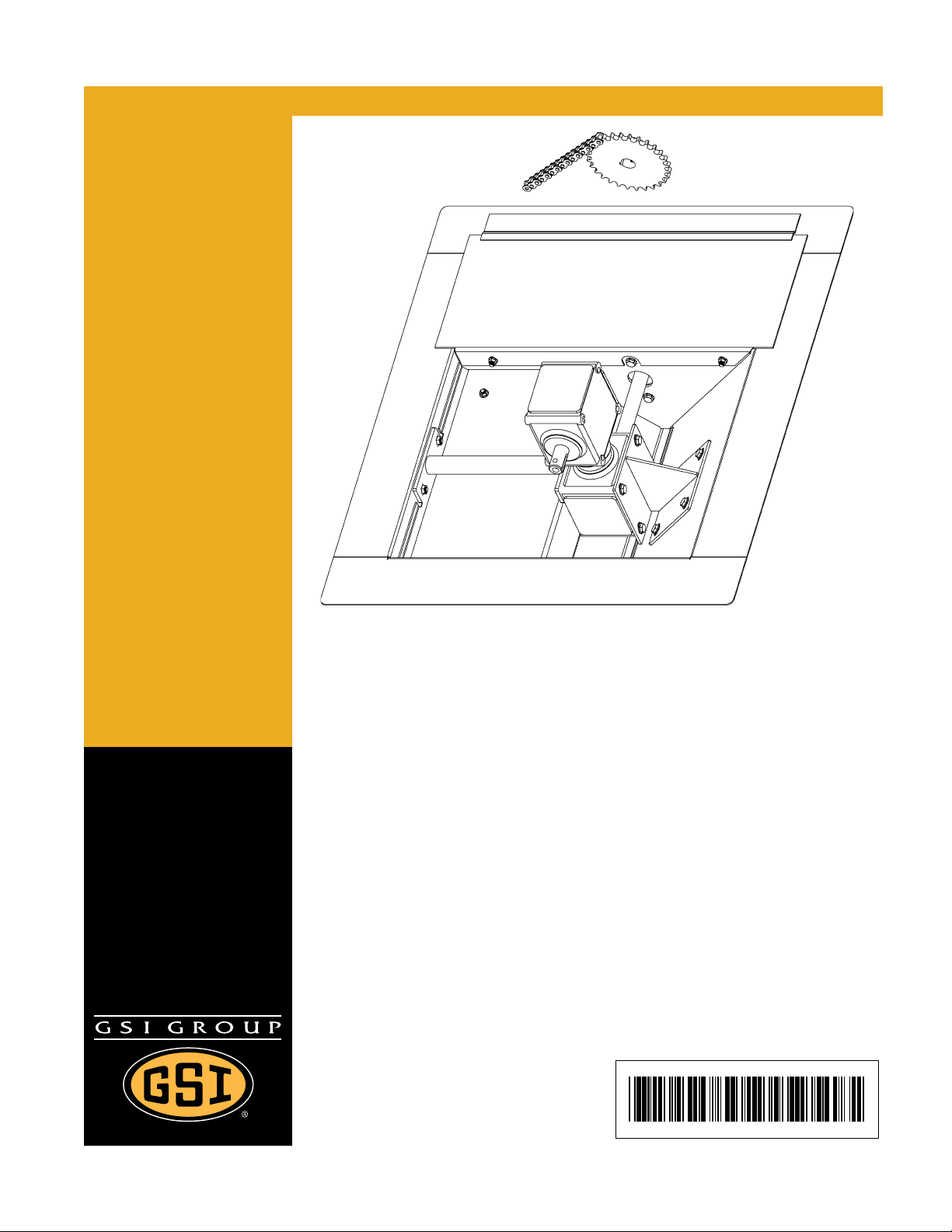
PNEG-1 71 6
Gearbox Input Speed
Reduction Packages
Installation Manual
PNEG-1716
Date: 06-08-10
Page 2

2 PNEG-1716 Gearbox Input Speed Reduction Packages
Page 3

Table of Contents
Contents
Chapter 1 Safety .....................................................................................................................................................4
Safety Guidelines .................................................................................................................................. 4
Operator Qualifications ....................................... ... ... .... ... ... ... .... ... ... ..................................................... 7
Chapter 2 General Information .............................................................................................................................8
Chapter 3 Installation ............................................................................................................................................9
Removal and Installation ....................................................................................................................... 9
Chapter 4 Parts List .............................................................................................................................................13
Components ..................................... ............................................. ...................................................... 13
Chapter 5 Warranty ..............................................................................................................................................15
PNEG-1716 Gearbox Input Speed Reduction Packages 3
Page 4
1. Safety
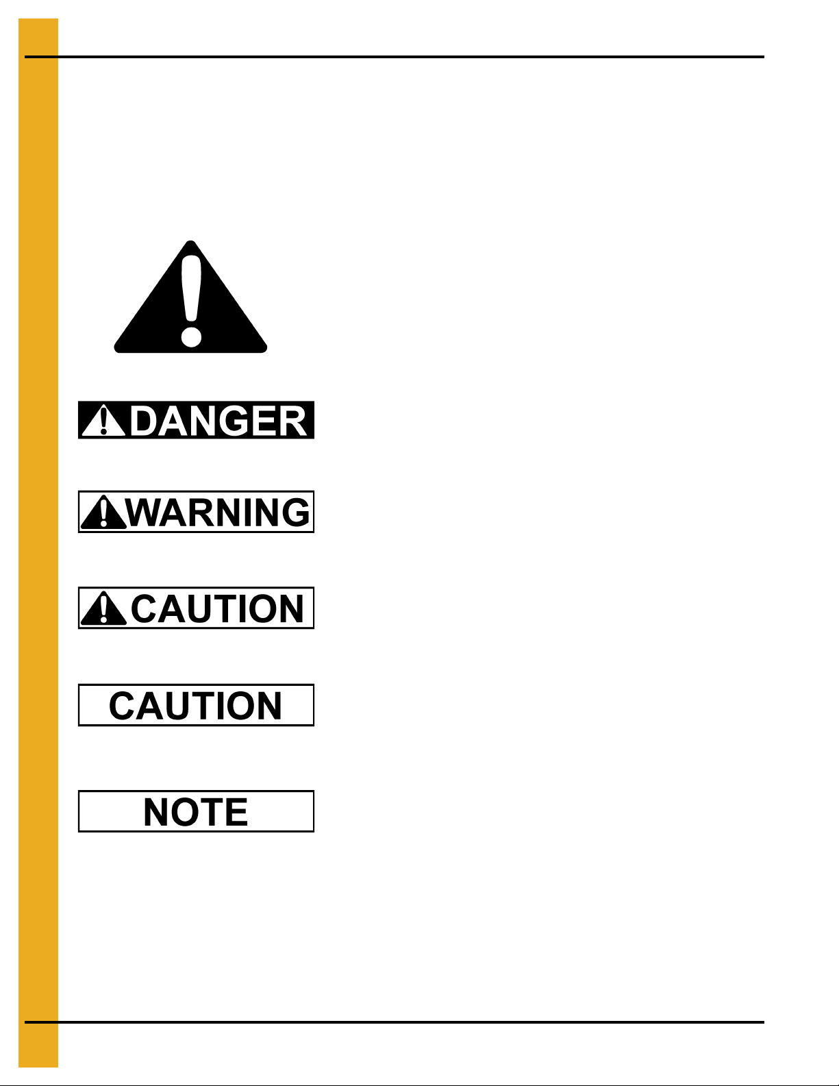
This is the safety alert symbol. It is used to alert you to
potential personal injury hazards. Obey all safety
messages that follow this symbol to avoid possible
injury or death.
WARNING indicates a potentially hazardous situation
which, if not avoided, could result in death or serious injury.
CAUTION indicates a potentially hazardous situation which,
if not avoided, may result in minor or moderate injury.
CAUTION used without the safety alert symbol indicates a
potentially hazardous situation which, if not avoided, may
result in property damage.
NOTE indicates information about the equipment that you
should pay special attention.
DANGER indicates an imminently hazardous situation
which, if not avoided, will result in death or serious injury.
Safety Guidelines
This manual contains information that is important for you, the owner/operator, to know and understand.
This information relates to protecting personal safety and preventing equipment problems. It is the
responsibility of the owner/operator to inform anyone operating or working in the area of this equipment of
these safety guidelines. To help you recognize this information, we use the symbols that are defined
below. Please read the manual and pay attention to these sections. Failure to read this manual and its
safety instructions is a misuse of the equipment and may lead to serious injury or death.
4 PNEG-1716 Gearbox Input Speed Reduction Packages
Page 5

Operate Unload Equipment Properly
• Untrained operators subject themselves and others to SERIOUS INJURY
or DEATH. NEVER allow untrained personnel to operate this equipment.
• NEVER work alone.
• Keep children and other unqualified personnel out of the working
area at ALL times. Refer to the Start-Up section of this manual for
diagrams of the work area.
• Make sure ALL equipment is locked in position before operating.
• NEVER start equipment until ALL persons are clear of the work area.
• Keep hands and feet away from the auger intake and other moving parts.
• NEVER attempt to assist machinery operation or to remove trash from equipment while
in operation.
• Be sure all operators are adequately rested and prepared to perform all functions of operating
this equipment.
• NEVER allow any person intoxicated or under the influence of alcohol or drugs to operate
the equipment.
• Make sure someone is nearby who is aware of the proper shut down sequence in the event of an
accident or emergency.
• ALWAYS think before acting. NEVER act impulsively around the equipment.
• NEVER allow anyone inside a bin, truck or wagon which is being unloaded by an auger or
conveyor. Flowing grain can trap and suffocate in seconds.
• Use ample overhead lighting after sunset to light the work area.
• Keep area around intake free of obstacles such as electrical cords, blocks, etc., that might
trip workers.
• NEVER drive, stand or walk under the equipment.
• Use caution not to hit the auger when positioning the load.
• ALWAYS lock out ALL power to the equipment when finished unloading a bin.
• Be aware of pinch points. A pinch point is a narrow area between two su rfaces that is likely to tra p
or catch objects and so is a potential safety hazard.
Operate Unload
Equipment Safely
1. Safety
PNEG-1716 Gearbox Input Speed Reduction Packages 5
Page 6

1. Safety
Wear Protective Clothing
Wear close fitting clothing and safety equipment appropriate
to the job.
Remove all jewelry.
Long hair should be tied up and back.
Safety glasses should be worn at all times to protect eyes
from debris.
Wear gloves to protect your hands from sharp edges on
plastic or steel parts.
Wear steel toe boots to help protect your feet from falling
debris. Tuck in any loose or dangling shoe strings.
A respirator may be needed to prevent breathing potentially
toxic fumes and dust.
Wear hard hat to help protect your head.
Wear appropriate fall protection equipment when working at
elevations greater than six feet (6').
Eye Protection
Gloves
Steel Toe Boots
Respirator
Hard Hat
Fall Protection
6 PNEG-1716 Gearbox Input Speed Reduction Packages
Page 7

1. Safety
Operator Qualifications
A. The User/Operator must be competent and experienced to operate auger equipment. Anyone who
works with or around augers must have good common sense in order to be qualified. These persons
must also know and meet all other qualifications, such as:
i. Any person who has not read and/or does not understand all operation and safety procedures
is not qualified to operate any auger systems.
ii. Certain regulations apply to personnel operating power machinery. Personnel under the age of
18 years may not operate power machinery, including augers. It is your responsibility, as owner
and/or supervisor, to know what these regulations are in your area or situation.
iii. Unqualified or incompetent persons are to remain out of the work area.
iv. O.S.H.A. (Occupational Safety and Health Administration) regulations state: “At the time of
initial assignment and at least annually thereafter, the employer shall instruct every employee
in the safe operation and servicing of all equipment with which the employee is, or will be
involved”. (Federal Occupational Safety and Health Standards for Agriculture. Subpart D,
Section 1928.57 (a) (6)).
B. As a requirement of O.S.H.A., it is necessary for the employer to train the employee in the safe
operating and safety procedures for this auger. The sign-off sheet is provided for your convenience
and personal record keeping. All unqualified persons are to stay o ut o f the work area at all times. It
is strongly recommended that another qualified person who knows the shut down procedure is in the
area in the event of an emergency.
Date Employee Name Supervisor Name
PNEG-1716 Gearbox Input Speed Reduction Packages 7
Page 8

2. General Information
Make certain everyone is clear before operating equipment.
The operator shall be aware of any unusual vibrations, noises and the loosening
of any fasteners.
Keep all safety shields and devices in place.
Keep hands, feet and clothing away from moving parts
Shut off and lock out power to adjust, service or clean.
8 PNEG-1716 Gearbox Input Speed Reduction Packages
Page 9

Removal and Installation
3. Installation
1. Remove the two (2) 5/16" serrated flange nuts that retain the inspection cover as shown in
Figure 3A
Figure 3A
.
2. Remove the inspection cover from the center well.
3. Unhook the idler sprocket tension spring from the idler sprocket bracket.
4. Rotate the idler sprocket bracket away from the chain.
5. Slide the clutch yoke driving jaw away from the clutch sprocket driven jaw as shown in Figure 3B.
Figure 3B
PNEG-1716 Gearbox Input Speed Reduction Packages 9
Page 10

3. Installation
6. Rotate the sprocket on the gearbox so that the connecting link of the chain is on the upper side.
7. Remove the connecting link from the two (2) ends of the chain.
8. Remove the chain from the center well.
9. Loosen the set screw in the sprocket that is on the gearbox input shaft.
10. Remove the sprocket and key from the gearbox input shaft as shown in Figure 3C.
Figure 3C
11. Inspect the key for damage. Replace if necessary.
12. Install the new larger sprocket onto the input shaft of the gearbox as shown in Figure 3D.
Figure 3D
10 PNEG-1716 Gearbox Input Speed Reduction Packages
Page 11

13. Align the face of the gear with the face on the clutch sprocket driven jaw.
NOTE: Both small and larger sprockets need to be aligned to each other.
3. Installation
Figure 3E
14. Gently tighten the set screw in the sprocket to hold its position on the shaft. A final tightening will
happen after the chain is installed.
15. Route the new longer chain around both sprockets.
16. Join the two (2) ends together with the appropriate connecting link.
17. Make a final position adjustment to the larger sprocket. It is vital that the sprocket on the input shaft
of the gearbox and the clutch sprocket on the driven jaw are inline. Failure to do so will result in
decreased life capacity of the chain itself and possible binding issues.
18. Once the proper position has been obtained, tighten the sprocket set screw.
19. If not already done, lubricate the chain.
20. Rotate the idler sprocket bracket back so that it engages the chain. Re-attach the idler sprocket
tension spring onto the idler sprocket bracket.
21. Make sure that the clutch driving jaw has been completely disengaged from the clutch sprocket
driven jaw.
PNEG-1716 Gearbox Input Speed Reduction Packages 11
Page 12

3. Installation
Figure 3F
22. Place the inspection cover back onto the center well.
23. Re-install the two (2) 5/16" serrated flange nuts so that the inspection cover is properly retained.
12 PNEG-1716 Gearbox Input Speed Reduction Packages
Page 13

Components
4. Parts List
GPS68GR
GPS10GR
CPS10GR
19% Reduction in Sweep Arm Flight Rotation, for GPS6 and GPS8 Units Only
Ref # Part # Description
1 GK80004 Sprocket, #50, 27 Tooth, Hardened, 1" Bore, with Set Screws and Keyway
2 GK1924 #50 Roller Chain, 48 Pitch
3 D32-0015 Connecting Link, #50 Roller Chain
3 S-8674 Offset Link, #50 Roller Chain
21% Reduction in Sweep Arm Flight Rotation, for GPS10 Units Only
Ref # Part # Description
1 GK80005 Sprocket, #50, 28 Tooth, Hardened, 1" Bore, with Set Screws and Keyway
2 GK80006 #50 Roller Chain, 52 Pitch
3 D32-0015 Connecting Link, #50 Roller Chain
3 S-8674 Offset Link, #50 Roller Chain
32% Reduction in Sweep Arm Flight Rotation, for CPS10 Units Only
Ref # Part # Description
1 GK2324 Sprocket, #60, 22 Tooth, Hardened, 1-1/4" Bore, with Set Screws and Keyway
2 GK4947 #60 Roller Chain, 45 Pitch
3 S-8618 Connecting Link, #60 Roller Chain
3 S-8619 Offset Link, #60 Roller Chain
PNEG-1716 Gearbox Input Speed Reduction Packages 13
Page 14

NOTES
14 PNEG-1716 Gearbox Input Speed Reduction Packages
Page 15

5. Warranty
9101239_1_CR_rev7.DOC (revised July 2009)
GSI Group, LLC Limited Warranty
The GSI Group, LLC (“GSI”) warrants products which it manufactures to be free of defects in materials and workmanship
under normal usage and conditions for a period of 12 months after sale to the original end-user or if a foreign sale,
14 months from arrival at port of discharge, whichever is earlier. The end-user’s sole remedy (and GSI’s only obligation)
is to repair or replace, at GSI’s option and expense, products that in GSI’s judgment, contain a material defect in materials
or workmanship. Expenses incurred by or on behalf of the end-user without prior written authorization from the GSI
Warranty Group shall be the sole responsibility of the end-user.
Warranty Extensions:
The Limited Warranty period is extended for the following products:
Product Warranty Period
Performer Series Direct Drive Fan Motor 3 Years
AP Fans and Flooring
Cumberland
Feeding/Watering
Systems
Grain Systems Grain Bin Structural Design 5 Years
Grain Systems
Farm Fans
Zimmerman
All Fiberglass Housings Lifetime
All Fiberglass Propellers Lifetime
Feeder System Pan Assemblies 5 Years **
Feed Tubes (1-3/4" and 2.00") 10 Years *
Centerless Augers 10 Years *
Watering Nipples 10 Years *
Portable and Tower Dryers 2 Years
Portable and Tower Dryer Frames and
Internal Infrastructure †
5 Years
* Warranty prorated from list price:
0 to 3 years - no cost to end-user
3 to 5 years - end-user pays 25%
5 to 7 years - end-user pays 50%
7 to 10 years - end-user pays 75%
** Warranty prorated from list price:
0 to 3 years - no cost to end-user
3 to 5 years - end-user pays 50%
† Motors, burner components
and moving parts not included.
Portable dryer screens included.
Tower dryer screens not included.
GSI further warrants that the portable and tower dryer frame and basket, excluding all auger and auger drive components,
shall be free from defects in materials for a period of time beginning on the twelfth (12
and continuing until the sixtieth (60
th
) month from the date of purchase (extended warranty period). During the extended
th
) month from the date of purchase
warranty period, GSI will replace the frame or basket components that prove to be defective under normal conditions of
use without charge, excluding the labor, transportation, and/or shipping costs incurred in the performance of this
extended warranty.
Conditions and Limitations:
THERE ARE NO WARRANTIES THAT EXTEND BEYOND THE LIMITED WARRANTY DESCRIPTION SET FORTH
ABOVE. SPECIFICALLY, GSI MAKES NO FURTHER WARRANTY OF ANY KIND, EXPRESS OR IMPLIED,
INCLUDING, WITHOUT LIMITATION, WARRANTIES OF MERCHANTABILITY OR FITNESS FOR A PARTICULAR
PURPOSE OR USE IN CONNECTION WITH: (I) PRODUCT MANUFACTURED OR SOLD BY GSI OR (II) ANY ADVICE,
INSTRUCTION, RECOMMENDATION OR SUGGESTION PROVIDED BY AN AGENT, REPRESENTA TIVE OR
EMPLOYEE OF GSI REGARDING OR RELATED TO THE CONFIGURATION, INSTALLATION, LAYOUT, SUITABILITY
FOR A PARTICULAR PURPOSE, OR DESIGN OF SUCH PRODUCTS.
GSI shall not be liable for any direct, indirect, incidental or consequential damages, including, without limitation, loss of
anticipated profits or benefits. The sole and exclusive remedy is set forth in the Limited Warranty, which shall not exceed
the amount paid for the product purchased. This warranty is not transferable and applies only to the original end-user. GSI
shall have no obligation or responsibility for any representations or warranties made by or on behalf of any dealer, agent
or distributor.
GSI assumes no responsibility for claims resulting from construction defects or unauthorized modifications to products
which it manufactured. Modifications to products not specifically delineated in the manual accompanying the equipment at
initial sale will void the Limited Warranty.
This Limited Warranty shall not extend to products or parts which have been damaged by negligent use, misuse, alteration,
accident or which have been improperly/inadequately maintained. This Limited Warranty extends solely to products
manufactured by GSI.
Prior to installation, the end-user has the responsibility to comply with federal, state and local codes which apply to the
location and installation of products manufactured or sold by GSI.
PNEG-1716 Gearbox Input Speed Reduction Packages 15
Page 16

This equipment shall be installed in accordance with
the current installation codes and applicable
regulations which should be carefully followed in all
cases. Authorities having jurisdiction should be
consulted before installations are made.
Copyright © 2010 by GSI Group
Printed in the USA
GSI Group
1004 E. Illinois St.
Assumption, IL 62510-0020
Phone: 1-217-226-4421
Fax: 1-217-226-4420
www.gsiag.com
 Loading...