

Page 1
PNEG-1708
GSI Modular Tower Dryer
TM-1008, TM-1010, TM-1012 and TM-1015
Construction Manual
PNEG-1708
Date: 08-01-11
Page 2

2 PNEG-1708 GSI Modular Tower Dryer
Page 3

Table of Contents
Contents
Chapter 1 Introduction .......................................................................................................................................... 4
Chapter 2 Safety ..................................................................................................................................................... 5
Safety Guidelines .................................................................................................................................. 5
General Safety Statement ..................................................................................................................... 6
Electrical Power Supply ........................................................................................................................ 6
Chapter 3 Safety Decals ........................................................................................................................................ 7
Safety Decal # DC-GBC-1A ................................ ... ... .... ... ... ... .... ... ... ... .................................................. 8
Safety Decal # DC-1943 ....................................................................................................................... 9
Safety Decals # DC-985, DC-990 and DC-991 ................................................ ... ................................ 10
Safety Decals # DC-987, DC-988 and DC-989 ................................................ ... ................................ 11
Safety Decals # DC-1061 and 420-1473-8 ......................................................................................... 12
Safety Decals # DC-1063 and DC-1064 ............................................................................................. 13
Information Decals .... ... ....................................................................................................................... 14
Chapter 4 Dryer Overview and Specifications .................................................................................................. 15
Dimensions and Capacities for all Models .......................................................................................... 18
Dimensions - TM-1008 ........................................................................................................................ 19
Dimensions - TM-1010 ........................................................................................................................ 20
Dimensions - TM-1012 ........................................................................................................................ 21
Dimensions - TM-1015 ........................................................................................................................ 22
Chapter 5 Required Tools and Critical Tool Characteristics ........................................................................... 23
Critical Tool Characteristics ................................................................................................................ 23
Comprehensive Tool List .................................................... ... .... ... ... ... ... ............................................. 28
Chapter 6 Unloading and Staging the Modules ................................................................................................ 29
Chapter 7 Placing and Installing the Base/Unload Module .............................................................................. 30
Base/Unload Module Placement Considerations ................... ....................................... ... ... .... ... ......... 30
Securing the Unload Module ............................................................................................................... 32
Chapter 8 Assembling Ladders, Platforms and Catwalks ............................................................................... 34
Crate as Work Bench ................................... .... ... ... ............................................................................. 34
Installing Outside Ladder with Safety Cage ........................................................................................ 35
Overview Catwalk and Platform Assembly ......................................................................................... 39
Attaching Catwalks and Platforms to Dryer Modules .................... ... ... ... ....................................... ... ... 40
Chapter 9 Burner/Blower Module - Special Considerations ............................................................................ 48
Chapter 10 Lifting and Stacking the Modules ................................................................................................... 51
Overview for Safety ........................................................................................................................... 51
Recommended Stacking Order: Model 800 Series Dryer ................................................................. 52
Recommended Stacking Order: Model 1010 Series Dryer ............................................................... 53
Recommended Stacking Order: Model 1200 Series Dryer ............................................................... 54
Recommended Stacking Order: Model 1500 Series Dryer ............................................................... 55
Lifting ................................................................................................................................................. 56
Chapter 11 Electrical Connections ................................. ...................... ....................... ....................................... 64
Electrical Overview Minimal Connections .......................................................................................... 64
Air Switch ....................................................................................................................
Flame Sensor and Ignitor Wires (Spark Plug) ................................................................................... 67
Bindicator, Outside Overheat and Moisture Sensor .......................................................................... 69
Plenum Temperature ............................... ... .......................................... .... ... ...................................... 70
....................... 65
Chapter 12 Gas Pipe Train Overview ................................................................................................................. 71
Gas Pipe Train (Natural or LP) Overview Minimal Connections ..... ....................... ...................... ...... 71
Chapter 13 Finishing Touches: Removing Wrinkles and Dents from Screens .............................................. 73
Chapter 14 Warranty ............................................................................................................................................ 75
PNEG-1708 GSI Modular Tower Dryer 3
Page 4

1. Introduction
READ THIS MANUAL carefully to learn how to properly use and install equipment. Failure to do so could
result in personal injury or equipment damage.
INSPECT the shipment immediately upon arrival. The customer is responsible for ensuring that all
quantities are correct. The customer should report and note any damage or shortage on the bill of lading
to justify their claim to the transport company.
THIS MANUAL SHOULD BE CONSIDERED a permanent part of your equipment and should be easily
accessible when needed.
This warranty provides you the assurance that the company will back its products when defects appear
within the warranty period. In some circumstances, the company also provides field improvements, often
without charge to the customer, even if the product is out of warranty. Should the equipment be abused,
or modified to change its performance beyond the factory specifications, the warranty will become void
and field improvements may be denied.
4 PNEG-1708 GSI Modular Tower Dryer
Page 5
2. Safety
DANGER
WARNING
CAUTION
NOTICE
This is the safety alert symbol. It is used to alert you
to potential personal injury hazards. Obey all safety
messages that follow this symbol to avoid possible
injury or death.
WARNING indicates a hazardous situation which, if not
avoided, could result in death or serious injury.
CAUTION, used with the safety alert symbol, indicates a
hazardous situation which, if not avoided, could result in
minor or moderate injury.
NOTICE is used to address practices not related to
personal injury.
DANGER indicates a hazardous situation which, if not
avoided, will result in death or serious injury.
Safety Guidelines
This manual contains information that is important for you, the owner/operator, to know and understand.
This information relates to protecting personal safety and preventing equipment problems. It is the
responsibility of the owner/operator to inform anyone operating or working in the area of this equipment
of these safety guidelines. To help you recognize this information, we use the symbols that are defined
below. Please read the manual and pay attention to these sections. Failure to read this manual and its
safety instructions is a misuse of the equipment and may lead to serious injury or death.
PNEG-1708 GSI Modular Tower Dryer 5
Page 6

2. Safety
This product has sharp edges, which may cause serious injury. To avoid injury, handle
sharp edges with caution and always use proper protective clothing and equipment.
General Safety Statement
Our foremost concern is your safety and the safety of others associated with tower drye r. This manu al is
to help you understand safe operating procedures and some problems that may be encountered by the
operator and other personnel.
As owner and/or operator, you are responsible to know what requirements, hazards and precautions exist
and inform all personnel associated with the equipment or in the area. Safety precautions may be required
from the personnel. Avoid any alterations to the equipment, which may produce a very dangerous
situation, where SERIOUS INJURY or DEATH may occur.
You should consider the location of the tower dryer site relative to power line locations or electrical
transmission equipment. Contact your local power company to review your installation plan or for
information concerning required equipment clearance. Clearance of portable equipment that may be taken
to the tower dryer site should also be reviewed and considered. Any electrical control equipment in contact
with the tower dryer should be properly grounded and installed in accordance with National Electric Code
provisions and other local or national codes.
This product is intended for the use of grain drying. Any other use is a misuse of the product.
Sidewall bundles or sheets must be stored in a safe manner. The safest method of storing sidewall
bundles is laying horizontally with the arch of the sheet upward, like a dome. Sidewall sheets stored on
edge must be secured so that they cannot fall over and cause injury. Use care when handling and moving
sidewall bundles.
Personnel operating or working around equipment should read this manual. This manual must be
delivered with equipment to its owner. Failure to read this manual and its safety instructions is a misuse
of the equipment.
NOTE: A careful operator reduces risk of personal injury and equipment damage.
Electrical Power Supply
GSI recommends you contact your local power company and request that a representative inspect the
dryer installation. Be sure the wiring is compatible with the power company’s system and that adequate
power is supplied to the dryer.
6 PNEG-1708 GSI Modular Tower Dryer
Page 7

3. Safety Decals
Some of the required safety decals are placed on the dryer before shipping. The remainder are placed on
the dryer during electrical installations. The purpose of the safety decals is to immediately alert all
personnel to the hazards of an operating dryer. The safety decal does not replace the need for all
personnel to know and understand safe dryer operations and requirements. Read the “Dryer Operations
and Service Manual”.
NOTE: Safety decals should be read and understood by all people in or around the dryer area.
Safety decals on Pages 8-13 identify and give the location of all safety decals that should be on each tower
dryer. Safety decals are listed in numerical order.
If the safety decals on the following pages are not on the dryer, or if they are damaged, immediately
contact GSI for replacement safety decals.
GSI Decals
1004 E. Illinois St.
Assumption, IL. 62510
Phone: 1-217-226-4421
PNEG-1708 GSI Modular Tower Dryer 7
Page 8
3. Safety Decals
Rotating flighting will
kill or dismember.
Flowing material will
trap and suffocate.
Crusted material will
collapse and suffocate.
Keep clear of all augers.
DO NOT ENTER this bin!
Failure to heed these
warnings will result in
serious injury or death.
If you must enter the bin:
1. Shut off and lock out all power.
2. Use a safety harness and safety line.
3. Station another person outside the bin.
4. Avoid the center of the bin.
5. Wear proper breathing equipment or respirator.
DC-GBC-1A
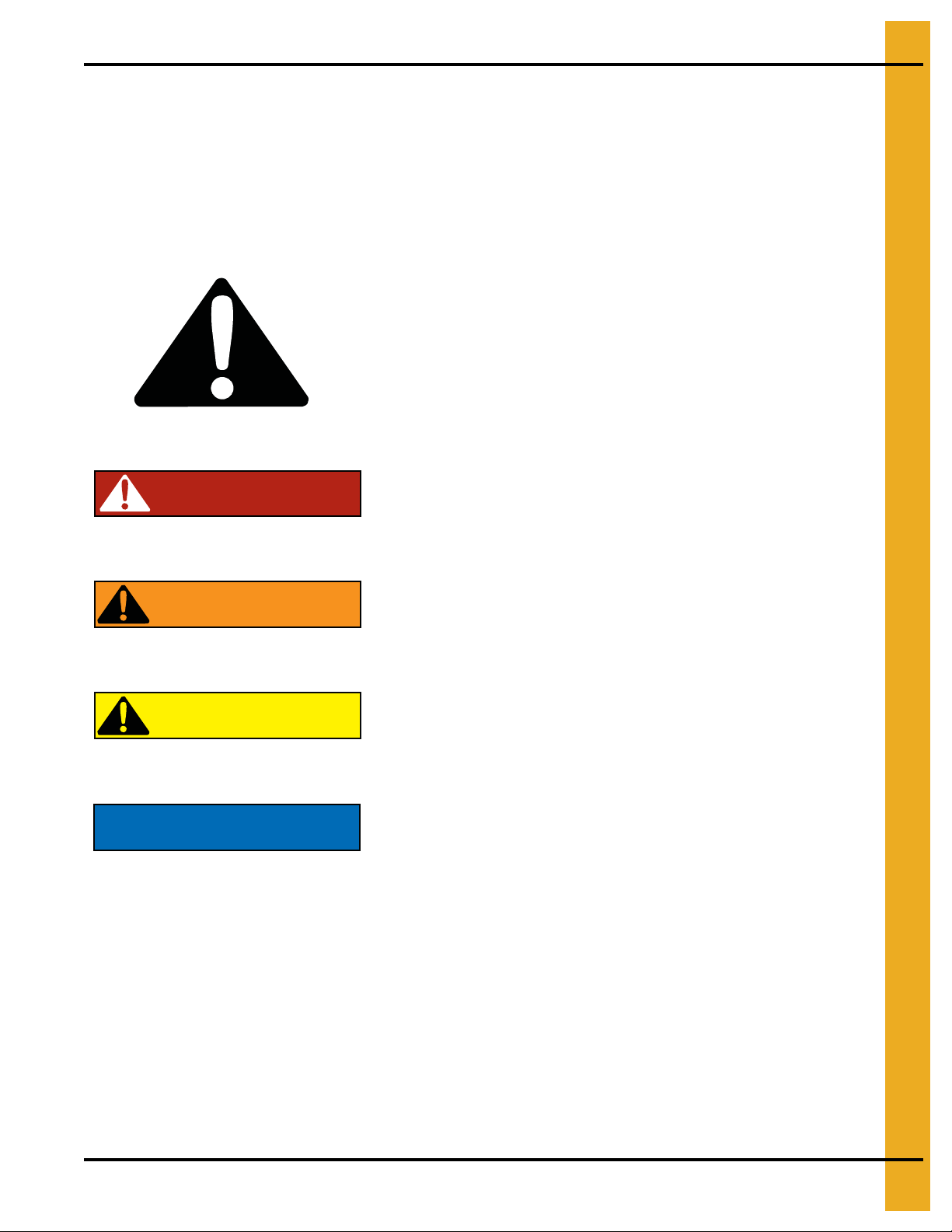
Tower roof access port with decals in place.
Inside view - Access port installed with
decals in place.
Outside view - Access port installed with
decals in place.
Safety Decal # DC-GBC-1A
Location of Decals
English and spanish decals are placed on inside of tower roof access port before shipping.
8 PNEG-1708 GSI Modular Tower Dryer
Page 9
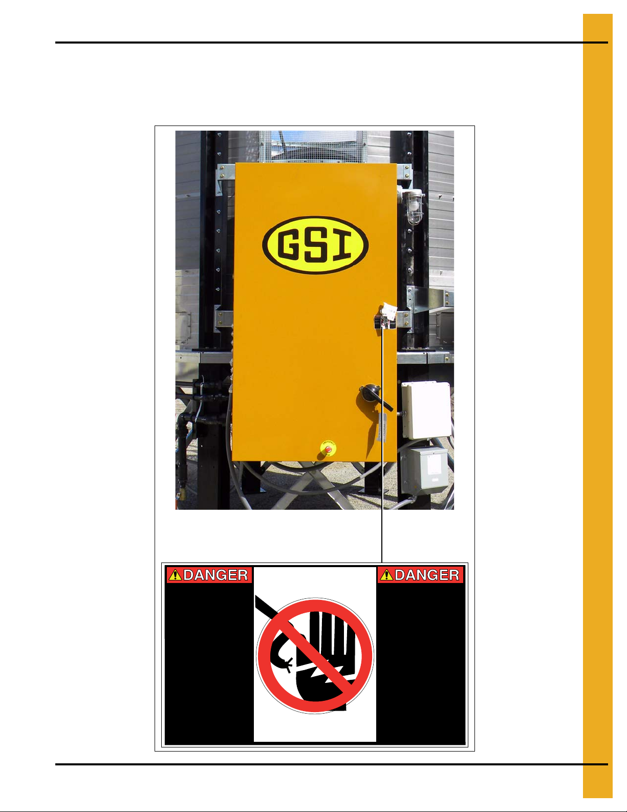
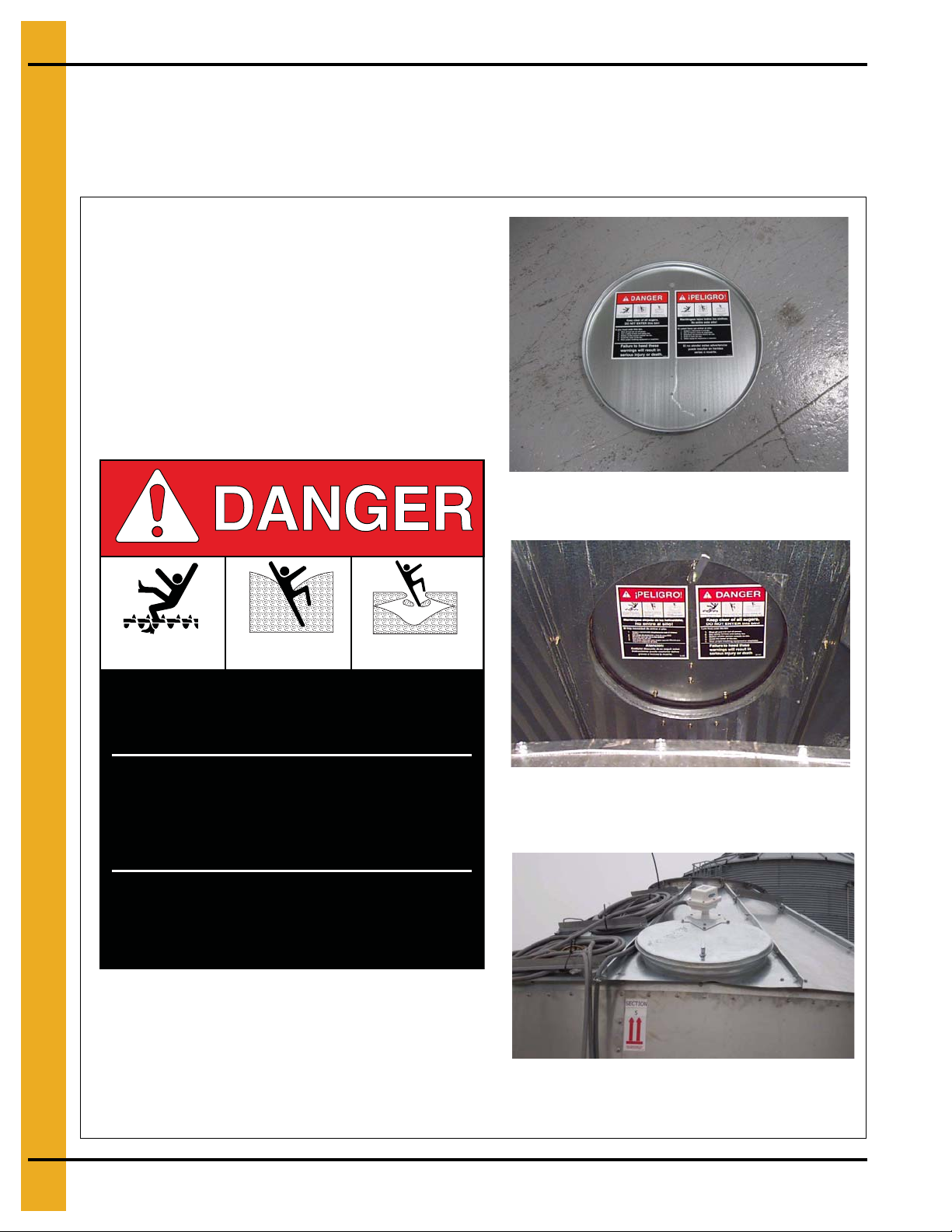
Safety Decal # DC-1943
Example - Electrical control system
Location of Decal
On outside of main power box and inside main power box door.
3. Safety Decals
PNEG-1708 GSI Modular Tower Dryer 9
HIGH VOLTAGE.
Will cause injury
or death.
Lockout power
before servicing.
HAUTE TENSION.
Causera des
blessures ou la
mort.
Bloquez le courant
avant de faire
l’entretien.
DC-1943
Page 10
3. Safety Decals
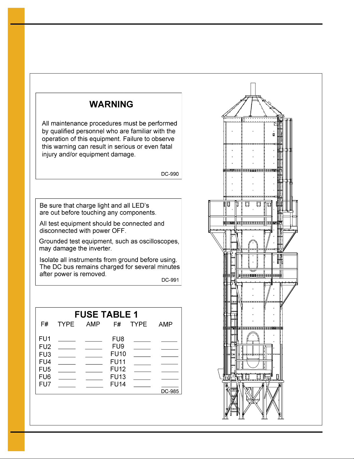
Safety Decals # DC-985, DC-990 and DC-991
Location of Decal
Inside main power box door, on same side as main electrical disconnect.
10 PNEG-1708 GSI Modular Tower Dryer
Page 11
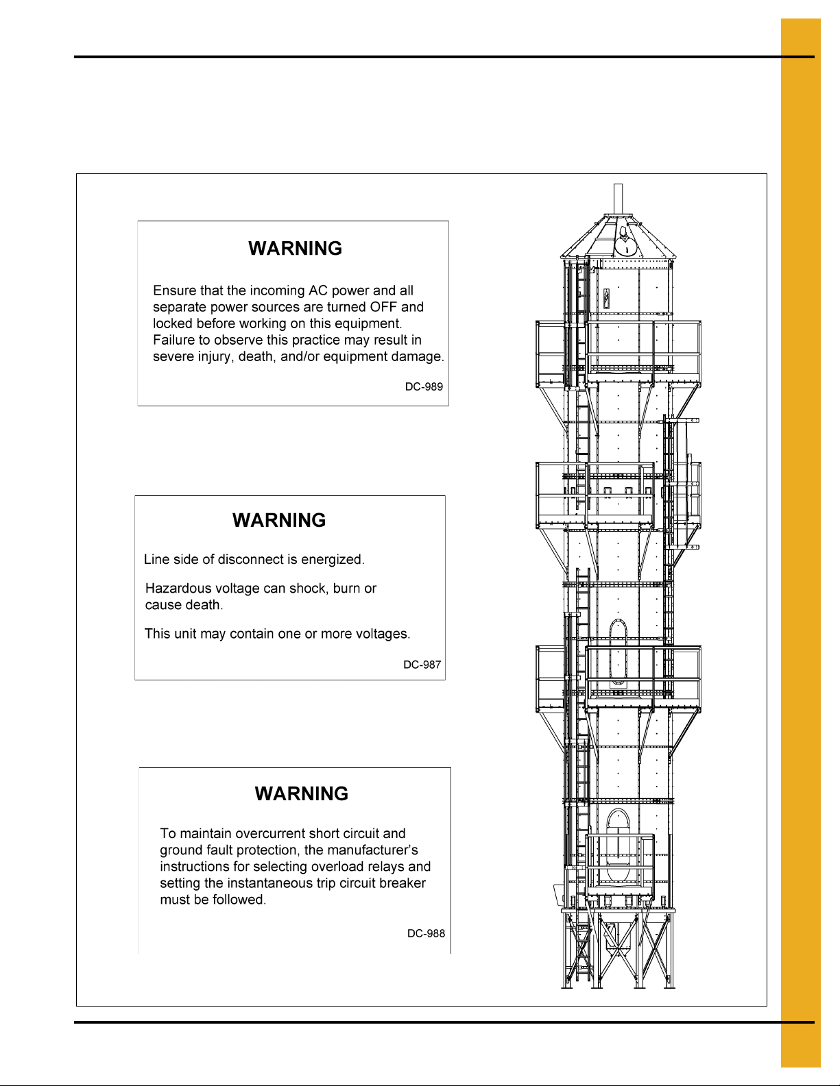
Safety Decals # DC-987, DC-988 and DC-989
Location of Decal
Inside main power box door, on same side as main electrical disconnect.
3. Safety Decals
PNEG-1708 GSI Modular Tower Dryer 11
Page 12
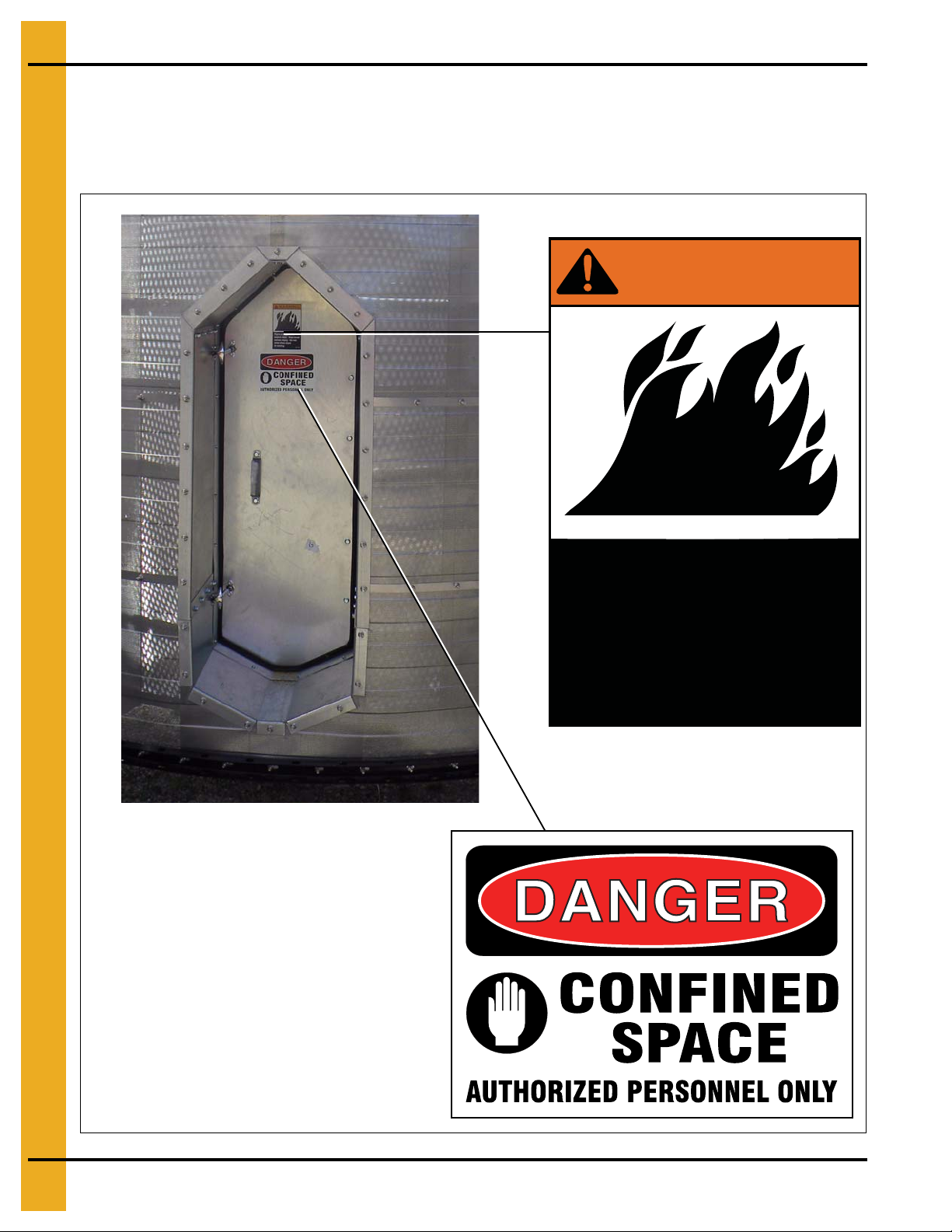
3. Safety Decals
Flame and pressure
beyond door. May
cause serious injury.
Do not enter when
dryer is running.
WARNING!
DC-1061
Safety Decals # DC-1061 and 420-1473-8
Location of Decal
On outside of heat module door.
12 PNEG-1708 GSI Modular Tower Dryer
420-1473-8
Page 13
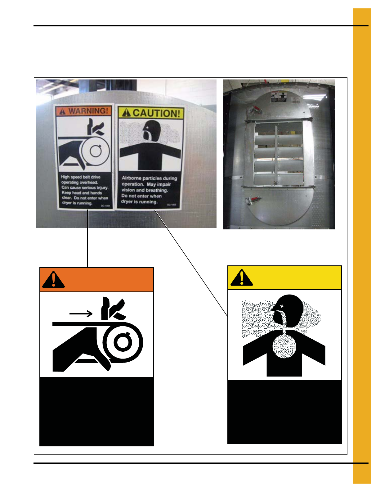
Safety Decals # DC-1063 and DC-1064
High speed belt drive
operating overhead.
Can cause serious injury.
Keep head and hands
clear. Do not enter when
dryer is running.
WARNING!
DC-1064
Location of Decal
On outside of cool module door.
3. Safety Decals
PNEG-1708 GSI Modular Tower Dryer 13
CAUTION!
Airborne particles during
operation. May impair
vision and breathing.
Do not enter when
dryer is running.
DC-1063
Page 14
3. Safety Decals
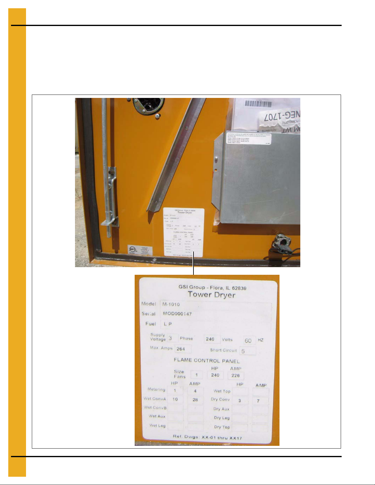
Example - Information decal
Information Decals
Nameplate for Main Power Box
Location of Decal
Inside main power box door, on same side as main electrical disconnect.
14 PNEG-1708 GSI Modular Tower Dryer
Page 15
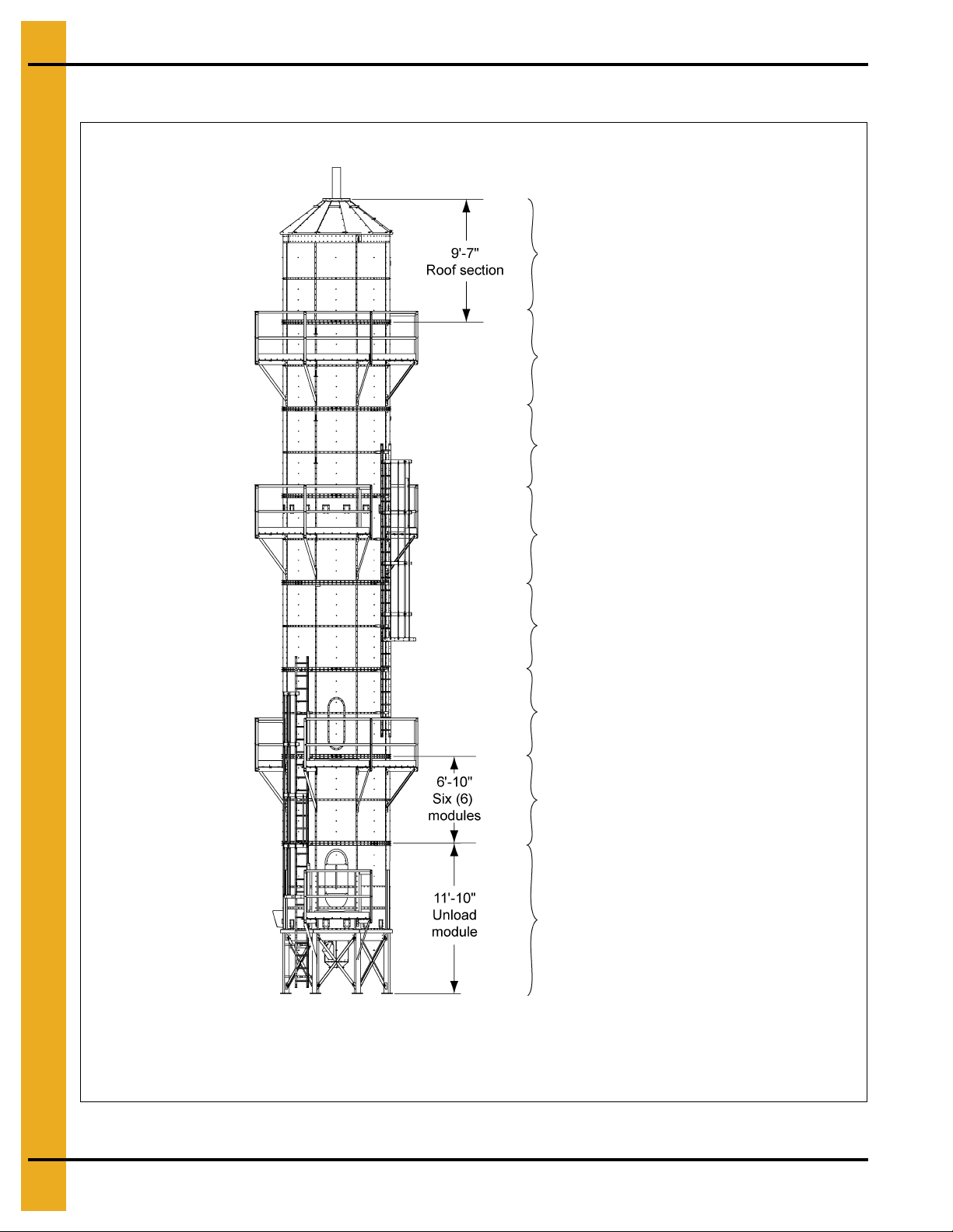
4. Dryer Overview and Specifications
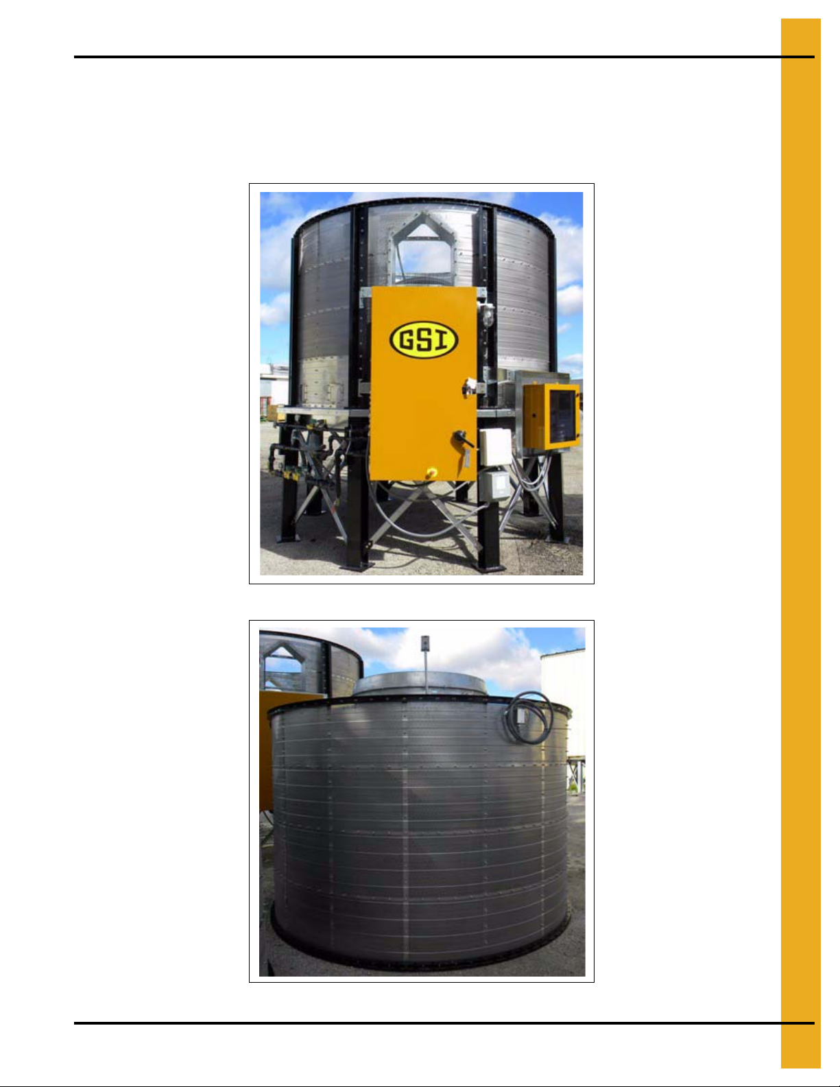
All models of the GSI Modular Tower Dryer include a base/unload module, a burner/blower module,
a roof module and one or more heat modules. Heat modules can be “empty” or with turners based on
owner preference.
Module 1 on ALL models.
NOTE: New dryers ship with corrugated sheets.
Figure 4A Base/Unload Module
Figure 4B Burner/Blower Module
PNEG-1708 GSI Modular Tower Dryer 15
Page 16
4. Dryer Overview and Specifications
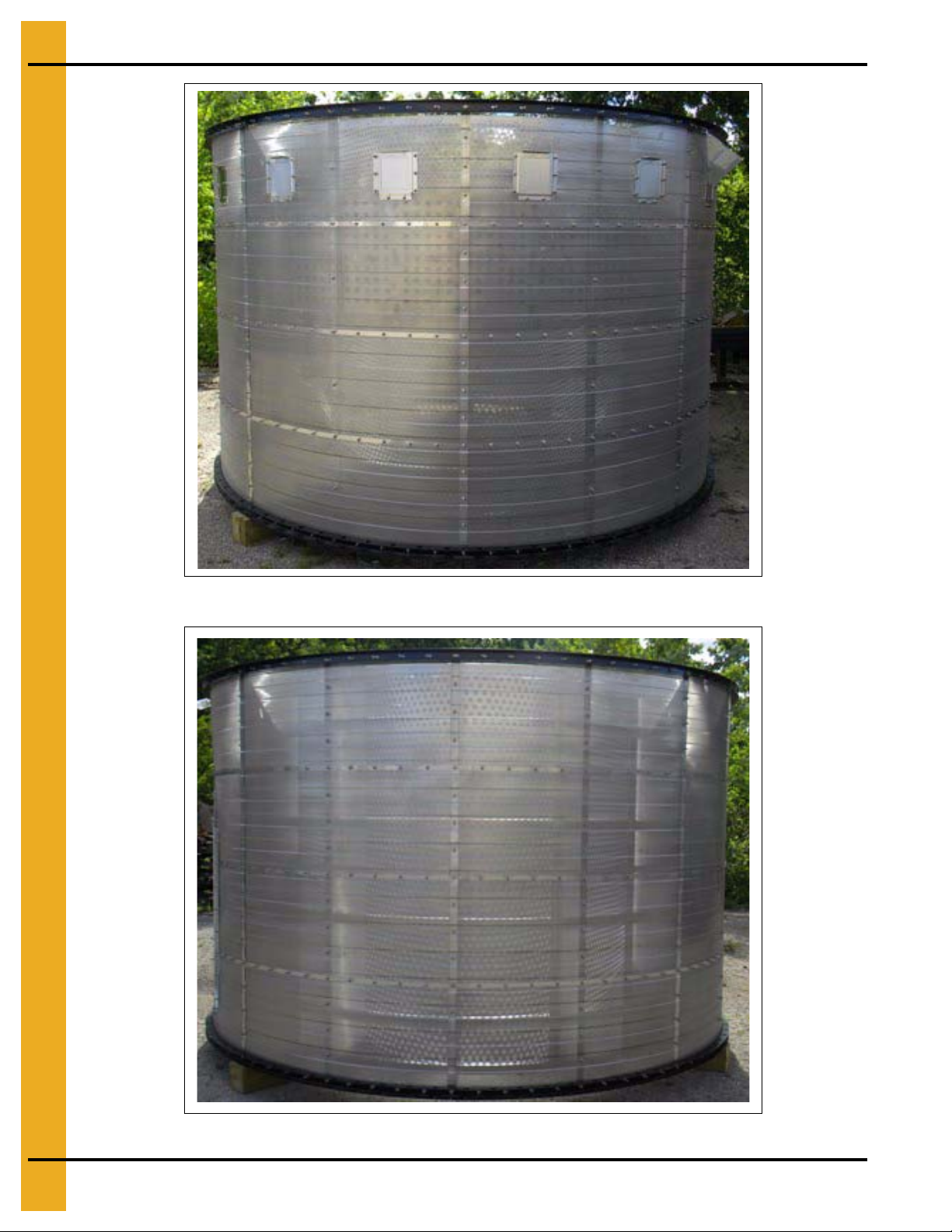
Figure 4C Heat Module - w/ Turners
Figure 4D Empty Heat Module
16 PNEG-1708 GSI Modular Tower Dryer
Page 17
4. Dryer Overview and Specifications
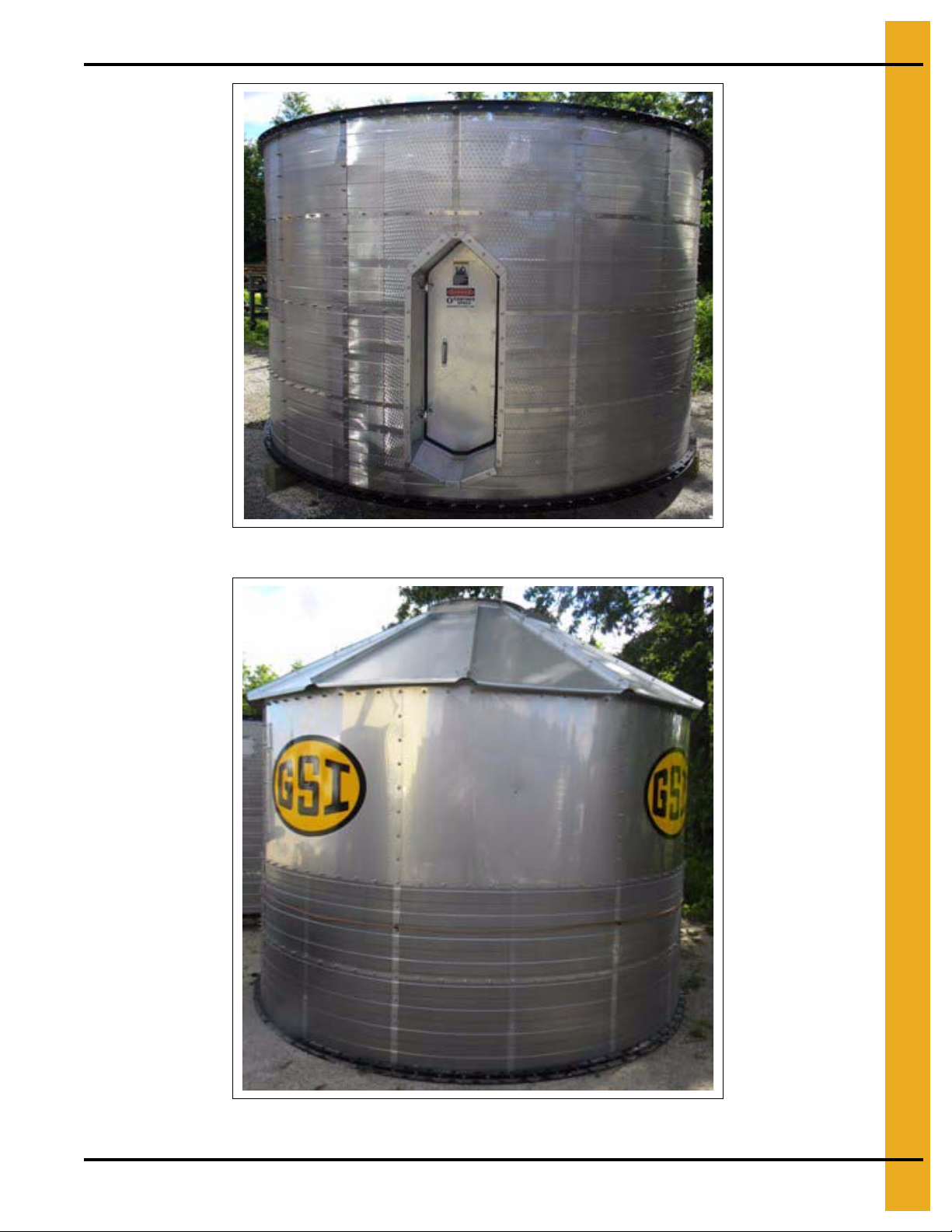
Figure 4E Heat Module - w/ Door Kit
Figure 4F Roof Module
PNEG-1708 GSI Modular Tower Dryer 17
Page 18
4. Dryer Overview and Specifications
Dimensions and Capacities for all Models
There are four (4) models of the GSI Modular Tower Dryer. Each model is 10' 10" in diameter.
1. TM-1008
2. TM-1010
3. TM-1012
4. TM-1015
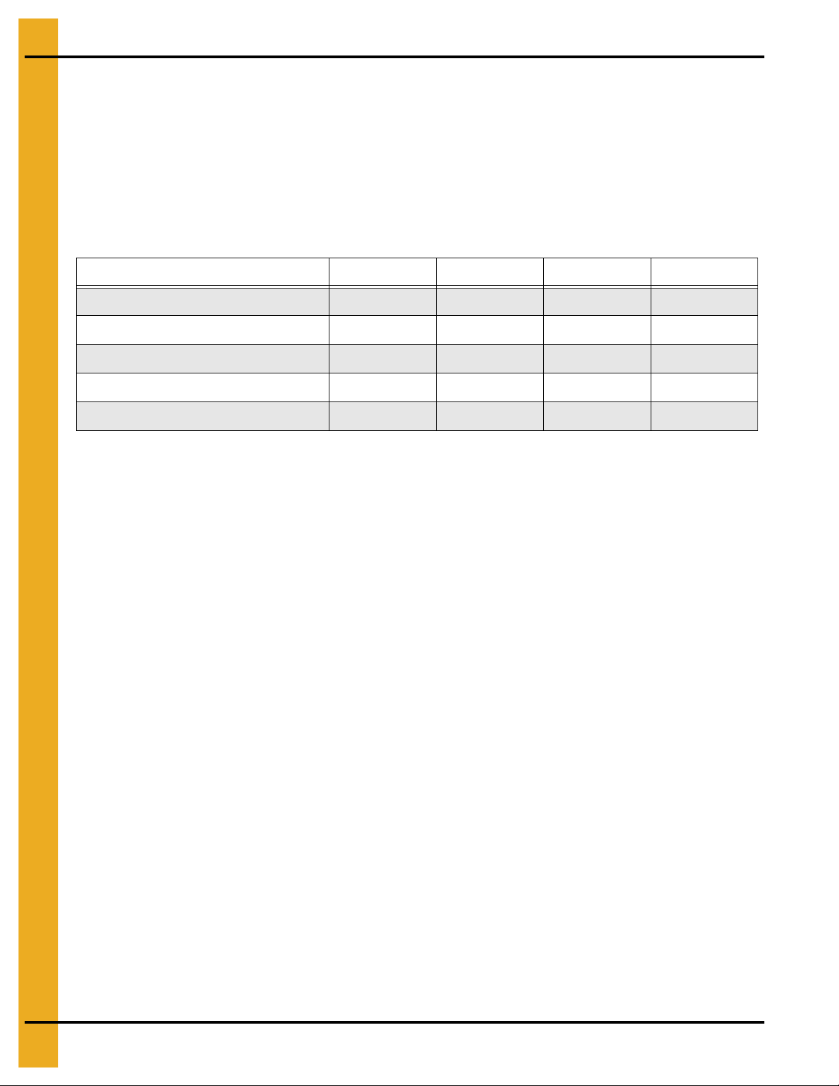
Model TM-1008 TM-1010 TM-1012 TM-1015
900 1125 1350 1690
BPH Capacity (20%-15%) 542 670 720 1010
BPH Capacity (25%-15%) 800 1000 1200 1500
BPH (Set in Maximum Cool) (20%-15%) 480 600 720 900
BPH (Set in Maximum Cool) (25%-15%) 900 1125 1350 1690
18 PNEG-1708 GSI Modular Tower Dryer
Page 19
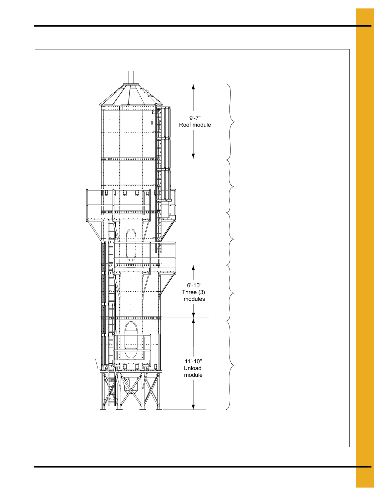
Dimensions - TM-1008
M-1008T - Five (5) modules total, usually
ships on two (2) trucks. All five (5)
modules are 10'-10" in diameter.
The 1008 model includes a platform at the base/unload,
ladders and safety cages to a stepover platform,
ladders and safety cages to a full catwalk and ladders
and safety cages to the roof access.
Module - 1 Base/unload
(See Figure 4A on Page 15.)
Module - 2 Heat module - burner/blower
(See Figure 4B on Page 15.)
Module - 3 Heat module - w/ door kit
(See Figure 4E on Page 17.)
Module - 4 Heat module - w/ turners
(See Figure 4C on Page 16.)
Module - 5 Roof module
(See Figure 4F on Page 17.)
Total weight = 18000 lbs.
NOTE: Please refer to Page 51 for individual section weights.
4. Dryer Overview and Specifications
Figure 4G TM-1008
PNEG-1708 GSI Modular Tower Dryer 19
Page 20
4. Dryer Overview and Specifications
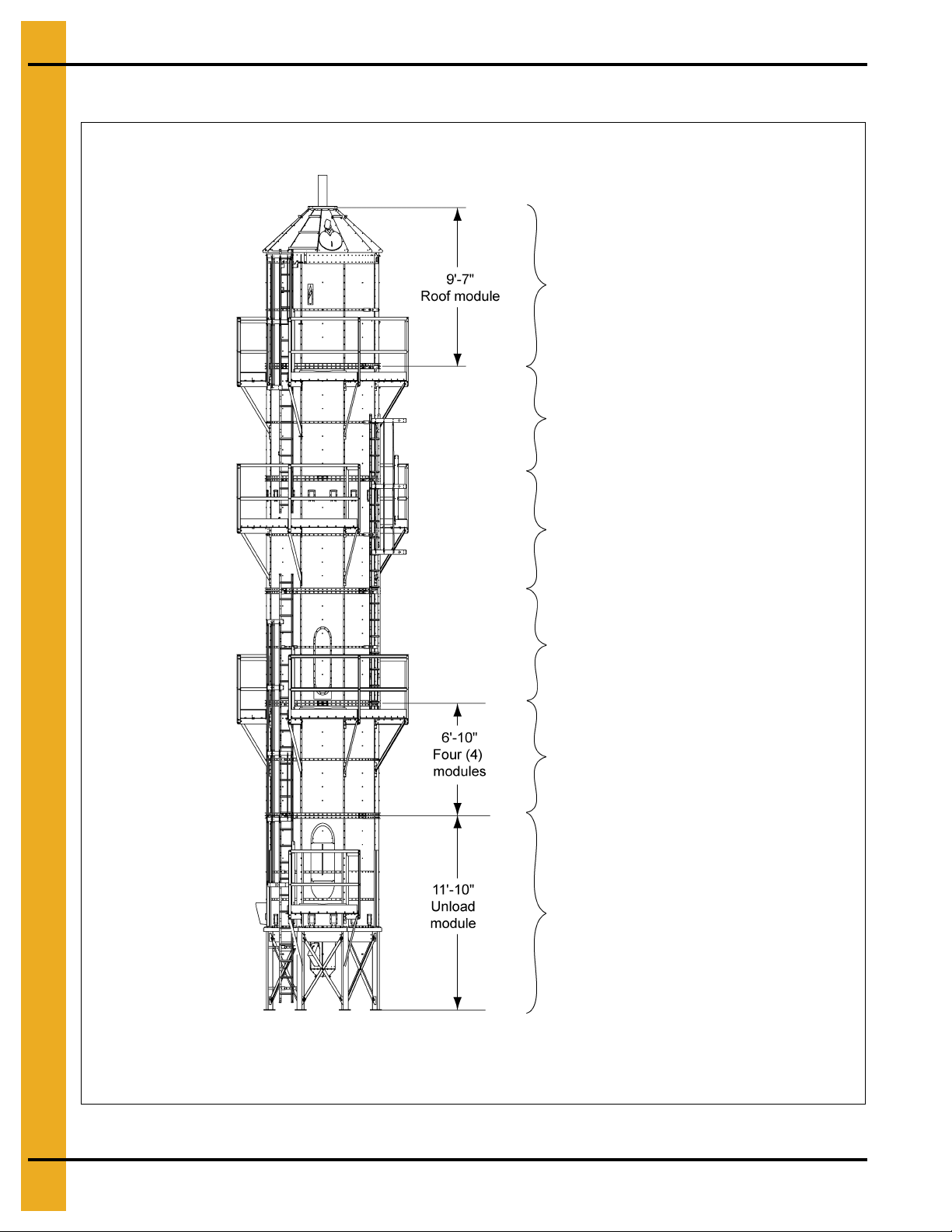
M-1010T - Six (6) modules total, usually
ships on two (2) trucks. All six (6)
modules are 10'-10" in diameter.
The 1010 model includes a platform at the
base/unload, ladders and safety cages to three (3)
full catwalks and ladders and safety cages to the
roof access.
Module - 2 Heat module - burner/blower
(See Figure 4B on Page 15.)
Module - 1 Base/unload
(See Figure 4A on Page 15.)
Module - 3 Heat module - w/ door kit
(See Figure 4E on Page 17.)
Module - 6 Roof module
(See Figure 4F on Page 17.)
Module - 5 Heat module - empty
(See Figure 4D on Page 16.)
Module - 4 Heat module - w/ turners
(See Figure 4C on Page 16.)
Total weight = 21645 lbs.
NOTE: Please refer to Page 51 for individual section weights.
Dimensions - TM-1010
Figure 4H TM-1010
20 PNEG-1708 GSI Modular Tower Dryer
Page 21
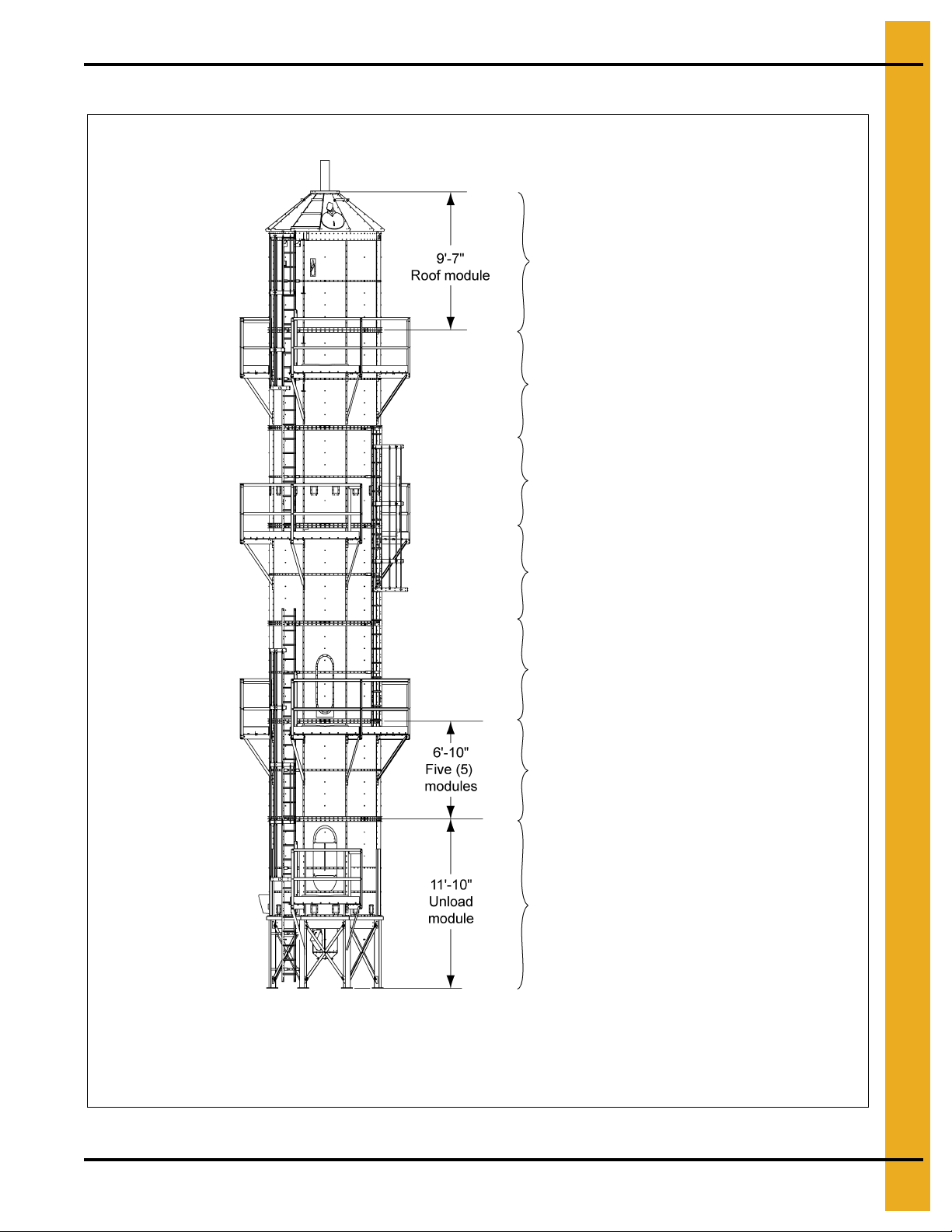
Dimensions - TM-1012
M-1012T - Seven (7) modules total, usually
ships on three (3) trucks. All seven (7)
modules are 10'-10" in diameter.
The 1012 model includes a platform for the
base/unload module, ladders and cages to a full
catwalk stepover platform, ladders and cages to
three (3) catwalks and ladders and cages to the
roof access.
Module - 1 Base/unload
(See Figure 4A on Page 15.)
Module - 2 Heat module - burner/blower
(See Figure 4B on Page 15.)
Module - 3 Heat module - w/ door kit
(See Figure 4E on Page 17.)
Module - 4 Heat module - empty
(See Figure 4D on Page 16.)
Module - 6 Heat module - empty
(See Figure 4D on Page 16.)
Module - 7 Roof module
(See Figure 4F on Page 17.)
Total weight = 23095 lbs.
Module - 5 Heat module - w/ turners
(See Figure 4C on Page 16.)
NOTE: Please refer to Page 51 for individual section weights.
4. Dryer Overview and Specifications
PNEG-1708 GSI Modular Tower Dryer 21
Figure 4I TM-1012
Page 22
4. Dryer Overview and Specifications
Module - 5 Heat module - w/ turners
(See Figure 4C on Page 16.)
M-1015T - Eight (8) modules total, usually
ships on three (3) trucks. All eight (8)
modules are 10'-10" in diameter.
The 1015 model includes a platform for the
base/unload module, ladders and cages to a
full catwalk stepover platform, ladders and
cages to three (3) catwalks and ladders and
cages to the roof access.
Module - 1 Base/unload
(See Figure 4A on Page 15.)
Module - 2 Heat module - burner/blower
(See Figure 4B on Page 15.)
Module - 3 Heat module - w/ door kit
(See Figure 4E on Page 17.)
Module - 4 Heat module - empty
(See Figure 4D on Page 16.)
Module - 7 Heat module - empty
(See Figure 4D on Page 16.)
Module - 6 Heat module - empty
(See Figure 4D on Page 16.)
Module - 8 Roof module
(See Figure 4F on Page 17.)
Total weight = 24545 lbs.
NOTE: Please refer to Page 51 for individual section weights.
Dimensions - TM-1015
22 PNEG-1708 GSI Modular Tower Dryer
Figure 4J TM-1015
Page 23
5. Required Tools and Critical Tool Characteristics
Equipping the field crew with the right tools is essential for a smooth installation. The GSI Modular
Tower Dryer requires a number of standard tools. Please pay particular attention to the following item
descriptions as the characteristics of the following tools are extremely important information for proper
installation. A comprehensive list of tools required to assemble and install the GSI Modular Tower Dryer
is included later in this chapter.
Critical Tool Characteristics
1. 1-1/8" Hammer drill star bit at least 12" long is REQUIRED. While the anchor bolts are 1" in
diameter, the holes for the anchor bolts MUST be 1-1/8" in diameter to allow room for the required
epoxy. Additionally, anchor bolts must be sunk deep enough so that no more than 2"-3" is above
the plate.
An air compressor hose is needed to blow out the dust from the holes prior to dropping in the anchor
bolts and epoxy. (See Figure 5A.)
2. Air compressor with hose: After drilled the holes for the anchor bolts, an air compressor with hose
is REQUIRED in order to blow all dust and debris out of the holes.
Figure 5A Anchor Bolts Sunk - No More than 3" Remains above Plate
3. Punches: 1/4" Line up punches - at least 8
5/8" line up punches - at least 8
Ideally, during the installation process, crews will work in two (2) person teams with one team working
inside the dryer and one team working outside the dryer. Each crew member should have at least
two (2) punches available to them.
Punches should be long enough to provide significant leverage to the user and should have narrow
and pointed tips to facilitate the initial punch placement. (See Figure 5B and Figure 5C on Page 24.)
PNEG-1708 GSI Modular Tower Dryer 23
Page 24

5. Required Tools and Critical Tool Characteristics
Figure 5B Line Up Punch and Hammer
Figure 5C Line Up Punch Inserted Through Connecting Channels of Dryer
24 PNEG-1708 GSI Modular Tower Dryer
Page 25

5. Required Tools and Critical Tool Characteristics
4. Socket sets and impact wrenches:
• 3/8" Drive 1/2" socket set
• 3/8" Drive 9/16" socket set
• 1/2" Drive socket set
• 15/16" Deep well 1/2" drive sockets
• 1/2" Deep well 1/2" drive sockets
• Short 1/2" 1/2" drive sockets
• 9/16" Deep well 1/2" drive sockets
• 1/2" Impact wrenches
• 3/8" Drive extensions (6" to 10") for 9/16" shallow socket
Accessing the bolts that connect sections of the dryer together requires passing through the hole in
the channel as shown in Figure 5D.
When installing, in all possible situations, place the impact on the bolt. Do NOT tighten the nut
as it will not lock down on the ring. Always tighten the bolt. (See Figure 5D.)
Figure 5D Connecting channels often requires the use
of socket extensions. Please plan accordingly.
PNEG-1708 GSI Modular Tower Dryer 25
Page 26

5. Required Tools and Critical Tool Characteristics
5. Laser transit level tool: After placing the unload/base module on the concrete foundation and
establishing its proper orientation to other equipment it must be leveled. GSI strongly recommends
using a Laser transit leveling tool to level the unit. (See Figure 5E.) If a Laser transit is not
available, a carpenter’s level may be used.
It is critical to establish the base/unload module as level. Even a minor deviation at this level
will be a significantly greater deviation at the top section. Therefore, pay particular attention to
confirming the levelness of the base/unload module. Shims are available to assist with leveling the
base/unload module. (See Figure 5F.)
Figure 5E Laser Transit Level
Figure 5F
26 PNEG-1708 GSI Modular Tower Dryer
Page 27

5. Required Tools and Critical Tool Characteristics
Compression channel ledge
a. Compression channel: Regardless of what leveling tool is used, the prope r reference point f or
leveling the unload module of the dryer is the Compression Channel and NOT the base/leg
plates on the concrete. See Figure 5G for reference.
The Compression Channel is the “ledge” around the unload module of the dryer. Use this as the
reference point for leveling the unit. Do NOT use base plates/feet to determine whether or not unit
is level.
PNEG-1708 GSI Modular Tower Dryer 27
Figure 5G Unload Module with Compression Channel Marked
Page 28

5. Required Tools and Critical Tool Characteristics
Comprehensive Tool List
• C6 Epoxy gun
• 1/4" Line up punches
• 1/2" x 9/16" Box end combination wrenches
• 1/2" Open end wrenches
• 9/16" Open end wrenches
• 32 OZ Ball peen hammers
• 5/8" Line up punches
• Small pry bars
• 3/8" Drive socket and extension
• 3/8" Drive 1/2" socket set
• 3/8" Drive 9/16" socket set
• 1/2" Drive socket set
• 4' Level
• Vice grips
• 25' Tape measures
• 15/16" Wrenches
• 15/16" Deep well 1/2" drive sockets
• 1/2" Deep well 1/2" drive sockets
• Short 1/2" 1/2" drive sockets
• 9/16" Deep well 1/2" drive sockets
• Caulk gun and 2 tubes of clear silicone
• 36" Pipe wrenches (rigid aluminum)
• 48" Pipe wrench (rigid aluminum)
• 18" Pipe wrenches
• Torque wrench (all 3/8" grade 8 bolts will need 45 ft./lbs.)
• 20' Ladders
• 6' Ladders
• 3/8" High speed drill bits
• 5/16" High speed drill bits
• 1/2" Impact wrenches
• 1/2" Drills
•1-1/2" Sockets
• Cordless sawzall
• 1-1/2" Hammer drill
• 1-1/8" Bits (hammer drill star bits)
• 3/8" and 5/16" Bit for impact driver
• 100' with a four (4) way box
• Air compressor with hose
28 PNEG-1708 GSI Modular Tower Dryer
Page 29

6. Unloading and Staging the Modules
NOTE: Concrete and gravel make the best staging ground.
NOTE: Leave adequate space between modules to attach platforms and catwalks.
1. Place modules on ground that is as solid and level as possible. Soft ground/grass will make
preparation for installation more difficult. Concrete or gravel ground is preferable for pre-installation
work. If no gravel or concrete area is available for staging the modules, consider placing the modules
on 2 x 4’s or other blocking material to prevent the modules from sinking into the ground.
2. Place modules next to sequential modules (i.e. place Module 2 near Module 3 and Module 3 near
Module 4, etc.) to make the stacking and connection of multiple modules easier.
3. Leave at least 4' to 5' of space between each module. Catwalks and/or platforms are attached
to appropriate modules before modules are stacked upon each other and lifted into place.
(See Figure 6A.)
Figure 6A Unload and Staging Considerations
PNEG-1708 GSI Modular Tower Dryer 29
Page 30

7. Placing and Installing the Base/Unload Module
Base/Unload Module Placement Considerations
If the concrete foundation is ready and adequately cured, place the base/unload module on it and take
careful and complete consideration of the surrounding equipment. Be sure to consider any planned
options such as augers and any potential equipment to be added later.
1. Consider the location of the electrical box and control panel. Orient base/unload module so that
personnel will have adequate and safe access to the electrical box and control panel. Remember,
the Vision control box can be remote mounted. (See Figure 7A.)
2. Consider any auxiliary equipment that will be used with the GSI Modular Dryer. One set of X-braces
on the unload may be removed without compromising structural integrity to allow for easier access.
3. Ensure that there is adequate overhead clearance for the entire tower dryer height and that the
clearance between the dryer walls and other equipment is sufficient to allow for catwalks
and/or platforms. (See Figure 7B on Page 31.)
Figure 7A
30 PNEG-1708 GSI Modular Tower Dryer
Page 31

7. Placing and Installing the Base/Unload Module
Figure 7B Consider overhead clearance for the entire height of the dryer.
4. Ladder brackets are not pre-installed on modules. Consider installation location of ladders and
brackets. Note that ladder brackets will be offset at each catwalk and will not line up in a straight line.
(See Figure 7C.)
IMPORTANT: When planning dryer location, ladders brackets will serve as good reference point for
where catwalks and/or platforms will be placed higher up on the dryer. Be sure to
allow for adequate spacing and clearance between the module dryer wall AND the
platforms and/or catwalks that will be attached higher up and any other equipment
in the area.
Figure 7C Ladder Brackets - Indentify location on each
module and surrounding equipment considerations.
PNEG-1708 GSI Modular Tower Dryer 31
Page 32

7. Placing and Installing the Base/Unload Module
CAUTION
While it is normal to encounter rebar on occasion when drilling the holes for anchor
bolts, should this happen more than 3 or 4 times, it is necessary to contact GSI for
splice plates to complete the drilling of the anchor bolt holes. (See Figure 7D.)
Securing the Unload Module
1. After determining the orientation of the unload module, use a 1-1/8" drill bit at least 12" long to drill
holes for the anchor bolts.
NOTE: Anchor bolts are 1" in diameter but the hole for them must be 1-1/8" in diameter to allow for
the required epoxy.
NOTE: It may be necessary to loosen or remove the bolts on the X-braces to gain easier access to
the holes for the anchor bolts. If X-braces are removed or loosened to drill the anchor bolt
holes, be sure to tighten the X-braces again when done.
Figure 7D
2. Use a laser transit to level the unload module.
IMPORTANT: ALWAYS use the compression channel as the point of reference for estab lishing
the levelness of the unit.
(See Figure 7E.)
Never use the feet/anchor plates to determine levelness.
Figure 7E
32 PNEG-1708 GSI Modular Tower Dryer
Page 33

7. Placing and Installing the Base/Unload Module
Do NOT remove more than one set of X-braces on the base/unload module as doing
so may compromise the structural integrity of the dryer . One set may be remove d to
accommodate auxiliary equipment.
NOTE: Shims are provided to assist with leveling if necessary. (See Figure 7F.)
Figure 7F
3. After drilling the holes, all debris and fine material must be removed from the holes.
4. Use a compressed air hose to blow the dust and debris out. Then, drop anchor bolt in holes to confirm
depth is adequate.
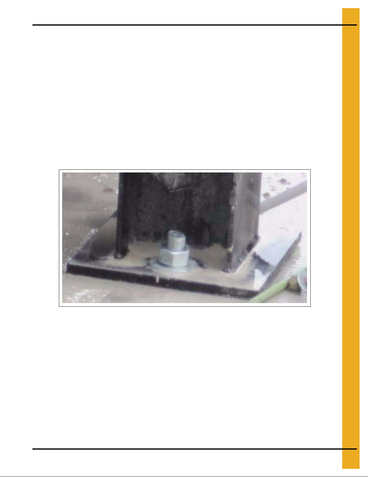
5. Once the unit is level, fill anchor bolt holes approximately 1/2" full with the provided epoxy. Press
anchor bolts in holes. (See Figure 7G.)
NOTE: Epoxy should ooze up and out of the hole at the base of the plate. If it does not, add epoxy
and repeat. No more than 2" to 3" of the bolt should remain above the plate. (See Figure 7G.)
6. After all anchor bolt holes have been filled with epoxy and all anchor bolts have been inserted into
the holes to the proper depth, allow epoxy to set for 4 to 6 hours before installing and tig htening nuts
or stacking another module of the dryer on top of it.
CAUTION
Figure 7G
PNEG-1708 GSI Modular Tower Dryer 33
Page 34

8. Assembling Ladders, Platforms and Catwalks
Crate as Work Bench
Because the base/unload module requires the epoxy to set for a MINIMUM of 4 hours before other
modules can be set on top of it, this is an excellent time to begin assembly of the ladders, platforms and
catwalks. Once the crate is empty, use a hammer to pound the exposed nails and/or staples back into the
frame so that the surface is smooth.
The crate makes an excellent work bench for assembling items throughout the installation process.
(See Figure 8A and Figure 8B.)
Figure 8A Crate as Work Bench
Once the modules have been staged, open the crate that shipped with the dryer modules.
The crate contains catwalk and/or platform materials, ladders and safety cages, as well as the hoses for
pipe train.
Optional items such as an auger kit will also ship in crates. Installation instructions for optional accessories
are in separate installation manuals.
Unload the materials from the crate and place them nearby in like-item groups (i.e. gas train pipes
together, catwalk and platform flooring together, etc). (See Figure 8B.)
Figure 8B Shipping Crate
34 PNEG-1708 GSI Modular Tower Dryer
Page 35

8. Assembling Ladders, Platforms and Catwalks
Installing Outside Ladder with Safety Cage
Outside Ladder Bracket
Outside ladder brackets are not pre-installed prior to shipping. Pre-assemble safety cages on the ground
prior to attaching to the dryer.
Top Safety Cage
Pre-assemble the top safety cage as follows. (See Figure 8C, Figure 8D below and Figure 8F to
Figure 8H on Page 36.)
1. Snug bolt one formed ladder section to two (2) outside ladder stiffeners. Snug bolt four (4) safety
cage brackets to outside ladder stiffeners. (See Figure 8C.)
Figure 8C
2. Bolt pairs of safety cage hoop halves together. (See Figure 8D.)
Figure 8D
PNEG-1708 GSI Modular Tower Dryer 35
Page 36

8. Assembling Ladders, Platforms and Catwalks
LADDER BOL TS - insert bolts toward outside of ladder, so climbers do not snag
on bolt shafts.
Install all formed ladder sections so rungs with rough, textured side for
gripping are on top, so climbers do not slip.
3. Snug bolt safety cage hoops to safety cage brackets. (See Figure 8E and Figure 8F.)
Figure 8E
Figure 8F
4. Snug bolt seven (7) vertical supports to safety cage hop halves. (See Figure 8G.)
5. Snug bolt top safety cage assembly to outside ladder brackets. (See Figure 8G.)
6. Tighten all bolts.
7. Use splice plate between ladders sections to connect. (See Figure 8H.)
Figure 8G
WARNING
WARNING
36 PNEG-1708 GSI Modular Tower Dryer
Figure 8H
Page 37

8. Assembling Ladders, Platforms and Catwalks
Safety Cage Extensions
Install safety cage extensions from top safety cage to bell safety cage just above foundation as follows.
Quantity depends upon dryer model.
1. Splice outside ladder stiffeners with ladder stiffener splices. Snug bolt outside ladder stiffeners
behind formed ladder sections. (See Figure 8I.)
Figure 8I Close Up - Pointing to ladder stiffener splice.
Install ladder stiffener splice with four (4) bolts.
2. Install safety cage brackets and safety cage hoops like top safety cage.
3. Before lifting each section, tighten bolts in outside ladder with safety cage for that section.
As dryer is constructed, continue installing safety cage extensions to each section of dryer before
lifting it. (See Figure 8J.)
Figure 8J Close Up - Outside Ladder Brackets
PNEG-1708 GSI Modular Tower Dryer 37
Page 38

8. Assembling Ladders, Platforms and Catwalks
Figure 8K Ladder Bracket for Rings
Figure 8L Ladder Bracket for Sheets
38 PNEG-1708 GSI Modular Tower Dryer
Page 39

8. Assembling Ladders, Platforms and Catwalks
Catwalk plankCatwalk plank
Kick plate
Catwalk plankCatwalk plank
Catwalk plankCatwalk plank
Overview Catwalk and Platform Assembly
NOTE: This is a basic overview of the process as it relates to the Modular Tower Dryers and is intended
to be a general guide for catwalks and platforms as they are assembled on the GSI Modular
Tower Dryer.
Catwalk and platform parts are shipped in the shipping crate that accompanies the modules. Assemble all
floor planks and kick plates before assembling the dryer or stacking and connecting the modules. Use the
shipping crate as a work bench to assist in the assembly of kick plates, catwalks and platforms.
1. Match longer kick plates to longer catwalk platforms and match shorter kick plates to shorter
catwalk platforms.
2. Attach kick plates to planks with nuts and bolts. For safety purposes, all nuts should be to the inside.
3. Tighten fully with power impact. (See Figure 8M and Figure 8N.)
Figure 8M Catwalk Planks
Figure 8N Kick plate attached to catwalk plank.
Assembled on shipping crate as work bench.
NOTE: The assembly is shown lying upside down.
4. Attach the curved kick plates to the catwalk planks that will be used at the stepover sections
immediately off of ladders. Curved kick plates are provided for safety purpo ses and help prevent feet
or boots from slipping and getting wedged between the platform and the dryer wall. (See Figure 8O.)
Figure 8O Catwalk plank with curved kick plate for use at stepover locations.
PNEG-1708 GSI Modular Tower Dryer 39
Page 40

8. Assembling Ladders, Platforms and Catwalks
Attaching Catwalks and Platforms to Dryer Modules
Catwalks and platforms are attached to the appropriate modules while they are on the ground, before
modules are stacked on other modules or lifted into place on the unload module.
5. Remove four (4) bolts per seam on sections to attach catwalk support braces. Be careful not to push
bolts back into channel between the screens. If bolts are accidentally pushed back into the channel
when installing the catwalk support brackets, the easiest way to remove them is by creating an
extra-long handled wrench. An example of this is shown in Figure 8P. Attach a regular wrench to a
long pole, in this case one of the long safety cage bars was used. A crew member can then access
the bolt from the channel by reaching in with the extra-long wrench. Carpenter’s putty can be placed
on the end to help pick up the bolt if needed. The wrench can then be used to hold the bolt in place
back in the proper hole as it is re-tightened.
Figure 8P
Figure 8Q
40 PNEG-1708 GSI Modular Tower Dryer
Page 41

8. Assembling Ladders, Platforms and Catwalks
Catwalk bracket
Support braces
Catwalk brace
Cut-off angle
Support braces
Nut to inside
6. Attach catwalk brackets as shown in Figure 8R.
NOTE: All brackets must attach facing/angling the same direction. In the example on the right, all
brackets will face to match the bracket being installed.
Figure 8R Attaching catwalk bracket to dryer module.
7. Assemble catwalk brace/support braces by connecting as shown in Figure 8S and Figure 8T using
one nut and one bolt.
IMPORTANT: Finger-tighten only at this time so that the pieces act like a hinge. Place nut to the
inside as shown in Figure 8S and Figure 8T. This helps prevent snagging.
Figure 8S
Figure 8T
PNEG-1708 GSI Modular Tower Dryer 41
Page 42

8. Assembling Ladders, Platforms and Catwalks
NOTE: All catwalk brackets and all catwalk brace should face the same direction.
Catwalk bracket
Catwalk brace
Gap to leave open for
ladder access.
Ladder brackets
8. Attach catwalk brace to dryer wall using the previously installed catwalk brackets. Catwalk brace
attach to outside of bracket. (See Figure 8U.) Tighten fully with impact.
Lower arm of catwalk brace connects to top hole of bracket and upper catwalk brace arm connects
to top hole of bracket. (See Figure 8U.)
In Figure 8U, the catwalk brackets all face . The catwalk brace attach to the outside of the
bracket and the catwalk brace all face .
9. Make sure, all catwalk brace should face the same direction.
Figure 8U
10. Make sure brackets and/or catwalk brace are NOT installed over the ladder braces as this would
block ladder installation. (See Figure 8V.)
Figure 8V
42 PNEG-1708 GSI Modular Tower Dryer
Page 43

8. Assembling Ladders, Platforms and Catwalks
Dryer
Align this SLOT away from dryer
and to HOLE in catwalk transition
Catwalk transition
No bolt used here
Catwalk transition
Dryer
No bolt used here
11. After attaching the catwalk brace to the catwalk brackets on the dryer wall, attach a catwalk transition
to the top of each catwalk brace. (See Figure 8X.)
IMPORTANT: Note the hole alignment on the catwalk transition. The “five (5) hole” pattern near the
center of the transition MUST be oriented so that the center hole is AWAY from the
dryer wall. (See Figure 8W and Figure 8X.)
Figure 8W
NOTE: Transition must line up on catwalk brace slot to slot. The SLOT indicated in the Figure 8W
must be oriented away from the dryer wall. Do NOT fill the middle hole of the transition.
PNEG-1708 GSI Modular Tower Dryer 43
Figure 8X
Page 44

8. Assembling Ladders, Platforms and Catwalks
Catwalk transition
Nuts and bolts
Catwalk plank
Kick plate
Dryer
12. Attach catwalk planks (with kick plates attached) to catwalk transitions.
13. There are two (2) planks between catwalk brace. The longer plank with the kick plate goes farther
away from the dryer wall with the kick plate on the outside and the shorter plank goes closest to the
dryer wall with the kick plate to the inside (to prevent stepping or slipping between the plank and the
dryer). (See Figure 8Y.)
Use nuts and bolts to connect catwalk planks to catwalk transitions.
Note in Figure 8Y only the inside plank has been places. It is located closer to the dyer wall. The
longer plank further from the dryer wall has not yet been placed and connected.
NOTE: Left nut is the middle hole mentioned in previous steps that had to be oriented away from
dryer wall. This is required so that the catwalk floor planks fit correctly. (See Figure 8Y.)
NOTE: Left nut shown in Figure 8Y is NOT in the correct slot.
Figure 8Y
44 PNEG-1708 GSI Modular Tower Dryer
Page 45

8. Assembling Ladders, Platforms and Catwalks
Stepover section
Handrail supports are
attached at this point.
Kick plates
14. Install the catwalk plank with the curved kick plate at the stepover point immediate beside ladders.
This is an added safety feature to help prevent feet from being wedged between the catwalk and
the dryer wall when stepping over or off a ladder. (See Figure 8Z.) This is the stepover section
immediately beside a ladder. Use ladder brackets for placement guidance.
Figure 8Z
15. Stepover kick plates are installed at stepover locations. These kick plates are lower to step-in
and higher where the handrail supports attach. (See Figure 8AA below, Figure 8AB and Figure 8AC
on Page 46.)
PNEG-1708 GSI Modular Tower Dryer 45
Figure 8AA
Page 46

8. Assembling Ladders, Platforms and Catwalks
Closed end of platform
Step-in end of platform
Handrail
Handrail
Figure 8AB
Figure 8AC
16. Attach handrail supports to catwalk brace as shown in Figure 8AD and Figure 8AE.
17. Attach handrails to handrail supports as shown in Figure 8AD and Figure 8AE. Make sure curved
side of handrails is to the inside for use. The sharper flat sides should be to the outside.
Figure 8AD
46 PNEG-1708 GSI Modular Tower Dryer
Figure 8AE
Page 47

8. Assembling Ladders, Platforms and Catwalks
Handrails
18. Connect handrails to the inside of supports as shown in Figure 8AF. Nuts should be to the outside
and the curved side of the handrail should be to the inside of the platform or catwalk for use.
(See Figure 8AF.) Note handrail orientation. Flat side goes to the outside away from the dryer.
Rounded side goes to the inside for hand safety. Outside away from the dryer. (See Figure 8AF.)
Also note the placement of connecting handrails to handrail support.
Figure 8AF
19. When assembling catwalks and platforms be sure to leave open the area between seams where
ladder brackets are located. Ladders will be installed at these points to connect the platforms
and catwalks.
20. Attach ladder to roof module at this time, BEFORE lifting roof to be connected to other modules.
21. Do not attach other ladders at this time. Ladders for all other modules below the roof module will be
attached AFTER the roof module and/or other modules are lifted and placed.
PNEG-1708 GSI Modular Tower Dryer 47
Page 48
9. Burner/Blower Module - Special Considerations
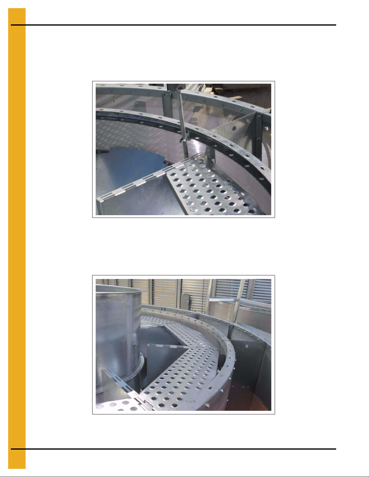
1. Before lifting and stacking modules, be sure the floor planks are installed for the burner/blower
module. These should be factory installed. The burner/blower module contains flooring to support
the user when entering the dryer to perform cleaning or maintenance duties.
The flooring planks for the burner/blower module are similar to catwalk planks but have “TABS” on
the ends to drop into slots in the burner/blower module. (See Figure 9A.)
Figure 9A
In Figure 9A, one plank has been placed. Note the longer planks will be placed to the outside (closer to
the dryer wall) and the shorter planks to the inside (closer to the burner/blower).
In Figure 9B, multip le flooring planks have been installed along the outer portion (closer to the dryer wall).
The inner planks have yet to be placed.
Figure 9B
48 PNEG-1708 GSI Modular Tower Dryer
Page 49

9. Burner/Blower Module - Special Considerations
Tabs and slots
Thermistor conduit
NOTE: The plank nearest the thermistor housing will need to be cut to allow it to drop into place.
This should be factory installed.
In Figure 9C, the installer is marking the plank so that it can be field cut for proper fit.
Figure 9D shows the marks where the plank needs to be cut for proper fit.
Note the tabs and slots on burner/blower floor planks. This helps differentiate them from catwalk planks.
(See Figure 9C.)
Figure 9C
Figure 9D
PNEG-1708 GSI Modular Tower Dryer 49
Page 50

9. Burner/Blower Module - Special Considerations
Cut plank
Figure 9E shows the field-cut plank installed in the burner/blower module. Note how the cut out now fits
around the thermistor.
Figure 9E
Figure 9F shows burner/blower planks installed.
Figure 9F
50 PNEG-1708 GSI Modular Tower Dryer
Page 51

10. Lifting and Stacking the Modules
Overview for Safety
Before lifting any modules make sure the lifting capacity of the crane is adequate for the total combined
weight of the module or modules, as well as any attached accessories such as catwalks, platforms
and ladders.
• Roof = 2200 lbs.
• Turner = 2550 lbs.
• Heat = 1450 lbs.
• TM-1008 Blower section = 4000 lbs.
• TM-1010 Blower section = 4100 lbs.
• TM-1012 Blower section = 4200 lbs.
• TM-1015 Blower section = 4500 lbs.
• Unload = 6250 lbs.
rd
• Heat section with 15 channels = 1675 lbs. (3
• Catwalks = 1140 lbs.
Module on every dryer.)
NOTE: Section weights do NOT include the additional weight of the catwalk that will be attached to the
appropriate section(s). Catwalk weight is approximately 1140 lbs.
The GSI Modular Tower Dryer is designed for quick and safe on-site installation. In order to maximize
safety, always perform as much work as possible as close to the ground as possible. Use the illustration
guides included later in this section for reference.
All sections of the GSI Modular Tower Dryer come labeled by the factory. Separate labels identify the dryer
sections by name and by their sequential placement in the overall stacking of the Modular Tower Dryer.
To determine the weight of multiple sections when lifting them together, simply add the section weights
together and if applicable, add the weight of the catwalk as well.
NOTE: It is recommen ded to attach ladder to roof module BEFORE lifting roof off of ground. Attach ladder
to section below roof module AFTER roof module is placed upon it.
NOTE: 8' Ladder section will only be able to be attached after the section is stacked on another section.
PNEG-1708 GSI Modular Tower Dryer 51
Page 52

10. Lifting and Stacking the Modules
Step 1:
Stack and connect
Roof to Module 4
Step 2:
Stack and connect Roof/4
to Module 3
Step 4:
Stack and connect
Roof/4/3/2 to Base
Base/Unload
This suggested sequencing plan maximizes safety and convenience, by performing most
work close to the ground.
IMPORTANT: Make sure crane is of adequate lifting capacity. The recommended strap length is 6' long.
NOTE: Catwalks, ladders and other accessories not shown for clarity. Be sure to include weight of accessories when
combining modules.
Step 3:
Stack and connect Roof/4/3
to Module 2
NOTE: If the crane is not sufficient to lift the combined weight of Roof/4/3/2 as shown,
replace step 4 with connecting Modules 3 and 2, stacking 3/2 on the base and then placing
Roof/4/3 on top of Base/2.
The GSI Modular Tower Dryer is designed to maximize safety and minimize assembly time. All models
will be assembled in similar fashion by: Lifting the roof module, stacking it on to the dryer module to be
directly underneath it and connecting those modules together. Then, the conjoin ed modules are lifted and
stacked on the next highest dryer module and connecting the modules. In this way, the vast majority
of work will be completed no more than ten feet (10') off of the ground. See the following figures on
Pages 52-55 for the specific recommendations for each model of the GSI Modular Tower Dryer.
NOTE: In all instances, six feet (6') lifting straps are recommended.
Recommended Stacking Order: Model 800 Series Dryer
Figure 10A Model 800
52 PNEG-1708 GSI Modular Tower Dryer
Page 53

10. Lifting and Stacking the Modules
Step 1:
Stack and connect
Roof to Module 5
Step 2:
Stack and connect
Roof/5 to Module 4
Step 4:
Stack and connect
Roof/5/4/3 to Module 2
Base/UnloadBase/Unload
Step 5:
Stack and connect
Roof/5/4/3/2 to Base
This suggested sequencing plan maximizes safety and convenience, by performing
most work close to the ground.
IMPORTANT: Make sure crane is of adequate lifting capacity. The recommended strap length is 6' long.
NOTE: Catwalks, ladders and other accessories not shown for clarity. Be sure to include weight of accessories
when combining modules.
NOTE: If the crane is not sufficient to lift the combined weight of
Roof/5/4/3/2 as shown, replace step 4 with connecting Modules
3 and 2, stacking 3/2 on the base and then placing Roof/5/4 on
top of Base/2/3.
Step 3:
Stack and connect
Roof/5/4 to Module 3
Recommended Stacking Order: Model 1010 Series Dryer
Figure 10B Model 1010
PNEG-1708 GSI Modular Tower Dryer 53
Page 54

10. Lifting and Stacking the Modules
Step 1:
Stack and connect
Roof to Module 6
Step 2:
Stack and connect
Roof/6 to Module 5
Step 5:
Stack and connect
Module 2 to Base
Step 6:
Stack and connect
Roof/6/5/4/3 to Base/2
Base/UnloadBase/Unload
Step 4:
Stack and connect
Roof/6/5/4 to Module 3
This suggested sequencing plan maximizes safety and convenience, by performing
most work close to the ground.
IMPORTANT: Make sure crane is of adequate lifting capacity. The recommended strap length is 6' long.
NOTE: Catwalks, ladders and other accessories not shown for clarity. Be sure to include weight of accessories
when combining modules.
NOTE: If the crane is not sufficient to lift the combined weight of
Roof/6/5/4/3 as shown, replace step 4 with connecting Modules 3 and 2,
stacking 3/2 on the base and then placing Roof/6/5/4 on top of base/2/3.
Step 3:
Stack and connect
Roof/6/5 to Module 4
Recommended Stacking Order: Model 1200 Series Dryer
Figure 10C Model 1200
54 PNEG-1708 GSI Modular Tower Dryer
Page 55
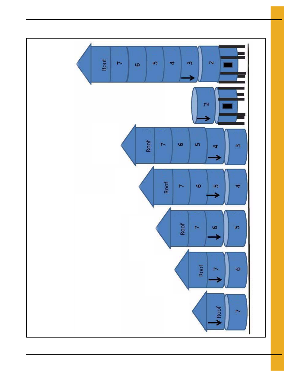
10. Lifting and Stacking the Modules
Step 1:
Stack and connect
Roof to Module 7
Step 2:
Stack and connect
Roof/7 to Module 6
Step 3:
Stack and connect
Roof/7/6 to Module 5
Step 6:
Stack and connect
Module 2 to Base
Step 7:
Stack and connect
Roof/7/6/5/4/3 to
Base/2
Base/UnloadBase/Unload
Step 5:
Stack and connect
Roof/7/6/5/4 to
Module 3
This suggested sequencing plan maximizes safety and convenience, by performing
most work close to the ground.
IMPORTANT: Make sure crane is of adequate lifting capacity. The recommended strap length is 6' long.
NOTE: Catwalks, ladders and other accessories not shown for clarity. Be sure to include weight of accessories
when combining modules.
NOTE: If the crane is not sufficient to lift the combined weight of
Roof/7/6/5/4/3 as shown, replace step 4 with connecting Modules 3
and 2, stacking 3/2 on the base and then placing Roof/7/6/5/4 on
top of Base/2/3.
Step 4:
Stack and connect
Roof/7/6/5 to Module 4
Recommended Stacking Order: Model 1500 Series Dryer
Figure 10D Model 1500
PNEG-1708 GSI Modular Tower Dryer 55
Page 56

10. Lifting and Stacking the Modules
Lifting
1. Use four (4) clevis hooks to connect the crane’s lifting straps to the module.
2. Remember, all modules except the roof, lift from four (4) lift points around the outside of the unit.
NOTE: The recommended strap length for lifting is 6' long.
Figure 10E
Figure 10F
56 PNEG-1708 GSI Modular Tower Dryer
Page 57

10. Lifting and Stacking the Modules
3. When maneuvering lifted modules across open ground, have personnel beside it to guide it and
minimize sway. When lifting the module on top of another module, be sure personnel have hard hats.
4. Carefully lower the module so that the connecting channels of each module are touching and can be
connected with nuts and bolts, however, do NOT lower fully at this time.
DO NOT REST THE UPPER MODULE(S) ON THE LOWER MODULE(S) AT THIS TIME. KEEP
SOME DEGREE OF TENSION ON THE MODULE FROM THE CRANE. ONLY FULLY LOWER
THE UPPER MODULE(S) ONCE ALL CONNECTIONS ARE MADE AT THE CONNECTING
CHANNELS WITH NUTS AND BOLTS.
Connecting Modules
5. Use the punches to line up connecting holes so that nuts and bolts can be loosely inserted at this time.
NOTE: Significant hammering and prying to accomplish hole alignment is to be expected.
Figure 10G
Figure 10H
NOTE: Ideally, crews will work in two (2) person teams with one team working inside the dryer and one
team working outside the dryer. Each person should have at least two (2) punches with narrow
pointed tips and long enough to provide significant leverage. Place step ladders and tools INSIDE
modules before stacking for ease of access.
PNEG-1708 GSI Modular Tower Dryer 57
Page 58

10. Lifting and Stacking the Modules
Ladder brackets
6. When stacking one module on top of another, be sure to line up ladder brackets.
In Figure 10I, ladder brackets are circled.
Figure 10I
7. Installation should proceed with a team of two (2) working to connect the modules from inside of the
dryer and two (2) working to connect the modules on the outside of the module.
For ease of assembly, place all tools, hardware and step ladders inside the module before stacking
another module on top of it.
Figure 10J shows a team of two (2) working to connect the modules on the inside.
Figure 10J
NOTE: For best results, use a two (2) person team on the inside and a two (2) person team on the outside
of the module dryer when connecting modules.
58 PNEG-1708 GSI Modular Tower Dryer
Page 59

10. Lifting and Stacking the Modules
Outside channels - Bolted every other hole
Inside channels - Bolted every hole
8. On all models of the GSI Modular Tower Dryer, the first two (2) connecting seams - between the
base/unload module and Module 2 and between Module 2 and Module 3 - require a nut and bolt in
EVERY hole of the connecting channel, both INSIDE and OUTSIDE of the dryer.
a. For all other connecting seam after/above the first two (2), every other hole may be bolted.
OUTSIDE of dryer: Two (2) connecting channels between two (2) modules. (See Figure 10K.)
NOTE: Every connecting hole must have a nut and bolt in place.
INSIDE of dryer: Two (2) connecting channels between two (2) modules. (See Figure 10K.)
PNEG-1708 GSI Modular Tower Dryer 59
Figure 10K
Page 60

10. Lifting and Stacking the Modules
14.4 Volt cordless impacts are NOT recommended for installation as they will
not sufficiently torque the bolts. Use electric impact and torque to 45 ft./lbs. If
bolts are not torqued properly, channels will co mpress when filled and bolts will
become loose.
Nut
9. Once all holes (or every other hole based upon which seam of the dryer you are working on at
the time) have a nut and bolt installed and are finger tightened, tighte n with an electric impact: torque
to 45 ft./lbs.
NOTE: When installing, in all possible situations, place the impact on the bolt. Do NOT tighten the
nut as it will not lock down on the ring. Always tighten the bolt. (See Figure 10M.)
NOTE: Accessing the bolts that connect sections of the dryer together requires passing through
the hole in the channel as shown. Narrow 3/8" drive sockets and/or extensions are required.
(See Figure 10L.)
CAUTION
Figure 10L Connecting Dryer Sections on Outside
Figure 10M Always tighten the bolt, not the nut to achieve torque specifications.
60 PNEG-1708 GSI Modular Tower Dryer
Page 61

10. Lifting and Stacking the Modules
Caulk seam
Channels
10. To stack additional sections, repeat the process as described above - always remember to line up
the ladder brackets on the modules -- and follow the suggested sequence illustrated earlier in
this chapter.
• Consider the orientation of each module as it pertains to ladders and catwalks before placing it
on the module for connection.
• Secure the module with clevis hooks and lifting straps. Lift with crane and place on top of
next module.
• Place section together but do not fully rest upper section on lower section.
• Use hammers and punches to line up connecting holes in channels both inside and outside
of dryer.
• Insert nut and bolt and finger tighten in every hole or every other hole as appropriate.
• Tighten with power impact.
• Caulk gaps with clear food-grade silicone as needed.
Figure 10N Gap Un-Caulked
Figure 10O Gap Caulked
NOTE:
ALWAYS stack and connect so that as much work as possible is done as close to the ground
as possible. Use the illustrations at the beginning of this chapter as a gu ide to accomplish this.
PNEG-1708 GSI Modular Tower Dryer 61
Page 62

10. Lifting and Stacking the Modules
Figure 10P
NOTE: It is normal for “dents” or “wrinkles” to appear in the screen during this process of stacking and
connecting. Most “dents” and/or “wrinkles” will be eliminated or greatly reduced in the final step of
the installation process.
62 PNEG-1708 GSI Modular Tower Dryer
Page 63

Venturi
3/8" Grill to venturi
5/16" Grill guard
3/8" Bolt
Burner/blower
5/16" Bolt
3/8" Bolt
Stiffener splice plate
(GT4-5074)
10. Lifting and Stacking the Modules
Figure 10Q
Stiffener Splice
Place stiffener splice plate over stiffener at joint of section 1 (base/unload section) and section 2
(burner/blower section).
NOTE: Seal the upper bolts 5/16" with electrical tape. To avoid drop into the dryer while placing
PNEG-1708 GSI Modular Tower Dryer 63
Figure 10R
stiffener splice.
Page 64

11. Electrical Connections
Vision control panel
Electrical Overview Minimal Connections
One of the most beneficial features of GSI Module Tower Dryers is the fact that much of the electrical
wiring is done at the plant prior to shipping. This is an advantage for the customer as fewer electrical
connections need to be made in field, thereby making is a quicker and safer installation. The connections
to be made in the field by the customer are:
• Air switch
• Flame sensor and ignitor wires (spark plug)
• Bindicator, outside overheat and moisture sensor
• Plenum temperature
• Gas pipe train (natural or LP) overview minimal connections
Adjustable overheat honeywell thermostat capillary is ran up to burner section.
These connections are reviewed in greater detail this section.
Another advantage of the GSI Modular Tower Dryer is the ability of the vision control box to be remote
mounted. The control box can remain on the unload module as shown and shipped or if the customer
prefers, it can be remote mounted in a more convenient location for user access or to allow auxiliary
equipment access to the tower dryer.
If the vision control panel remains mounted on the unload module of the GSI Modular Tower Dryer,
the protective rain shield should be installed as shown in Figure 11A to help protect it from the elements.
Figure 11A
64 PNEG-1708 GSI Modular Tower Dryer
Page 65

11. Electrical Connections
Air flow sensor
Wire clip
Rubber grommet
Air Switch
1. The air flow sensor connects to the grill guard on the fan with a rubber grommet and feeds through
to a connecting point on the outside of the electrical control box, which connects to the sensor on the
inside of the control box. (See Figure 11B, Figure 11C below and Figure 11D on Page 66.)
Figure 11B
2. Connect the air flow sensor (copper tubing) from the grill guard inside of dryer burner/blower to the
rubber grommet on the side of the outside control box. (See Figure 11C.)
PNEG-1708 GSI Modular Tower Dryer 65
Figure 11C
Page 66

11. Electrical Connections
Electrical control box
Rubber grommet
3. The rubber grommet connects to the air flow sensor inside of the control box. (See Figure 11D.)
Figure 11D
66 PNEG-1708 GSI Modular Tower Dryer
Page 67

11. Electrical Connections
Electrical control box
Holes through which flame sensor and
ignitor wires will be passed. See close
up in Figure 11F on Page 68.
Flame Sensor and Ignitor Wires (Spark Plug)
1. From inside the burner/blower module, the flame rod wire and the spark plug wire will be passed
through these holes as shown in Figure 11F.
2. The flame sensor and ignitor wires connect to the electrical control box.
PNEG-1708 GSI Modular Tower Dryer 67
Figure 11E
Page 68

11. Electrical Connections
Figure 11F
68 PNEG-1708 GSI Modular Tower Dryer
Page 69

11. Electrical Connections
Bindicator
Conduit
Bindicator
Conduit
Junction box
Copper tubing
Bindicator, Outside Overheat and Moisture Sensor
The bindicator is mounted on the roof with its wiring running the height of the dryer in conduit and is
connected by the customer is the field. (See Figure 11G.)
Figure 11G
The outside overheat (copper tubing) runs the circumference of the dryer on the roof module. It connects
to a junction box with conduit running the height of the dryer and is connected to the control panel by the
customer in the field. (See Figure 11H.)
Figure 11H
PNEG-1708 GSI Modular Tower Dryer 69
Page 70

11. Electrical Connections
Conduit clamps
Plenum Temperature
Plenum temperature is monitored through the wiring in the conduit that runs up through the burner/blower
floor. This was referenced in burner/blower module on Page 48, when installing the floor planks in the
burner/blower module as it was necessary to cut a floor plank to fit around the conduit.
Connecting this is also done in the field by the customer. (See Figure 11I.)
Figure 11I
After installing the conduit clamps, simply route the conduit through the clamps and close them.
(See Figure 11J.)
Figure 11J
70 PNEG-1708 GSI Modular Tower Dryer
Page 71

12. Gas Pipe Train Overview
Gas Pipe Train (Natural or LP) Overview Minimal Connections
Another beneficial feature of the GSI Modular Tower Dryer is the fact that the gas pipe train comes
pre-fitted and pre-assembled from the factory. This minimizes the connections that need to be made in the
field. The result, is a quicker and simpler installation process.
Only three (3) connections need to be made in the field to complete the gas train. (See Figure 12B.)
Figure 12A
The three (3) connecting hoses for the gas train are for:
• Liquid in
• Vapor out
• Return to burner
All three (3) are shown in the Figure 12A and ship in the crate along with catwalks, platforms and
other hardware.
Each hose has unique fittings and can only be installed in the proper location.
Figure 12B
PNEG-1708 GSI Modular Tower Dryer 71
Page 72

12. Gas Pipe Train Overview
3/4"
1"
1. The largest connecting hose connects inside the dryer for the return to blower. (See Figure 12C.)
Figure 12C
2. The remaining two (2) connecting hoses are installed inside the dryer as shown.
NOTE: All three (3) connecting hoses are pre-sized for correct connections and cannot be connected in
the wrong location as a result.
72 PNEG-1708 GSI Modular Tower Dryer
Page 73

13. Finishing Touches: Removing Wrinkles and Dents from Screens
During the installation process it is common for screen to “dent” or “wrinkle” from the pressures and
stresses of assembling. Examples of “denting” and “wrinkling” in the screens are circled in the Figure 13A.
They are often most visible in bright, reflective sunlight. Removing (or grea tly minimizing) these dents and
wrinkles is one of the final steps in the installation process. When removing wrinkles, work from the
top down.
1. Using all proper safety equipment and precautions, crew members should loosen the nuts on the
nearest columns one at a time until the “dent/wrinkle” literally “pops” out. Then, the nut(s) can
be re-tightened.
In Figure 13A, the columns in which the nuts should be loosened are between the arrow marks.
2. On occasion, it may be necessary to loosen the nuts connecting modules together. If this is the case,
ALWAYS re-tighten with impact when “wrinkle/dent” has “popped” out.
NOTE: In Figure 13A, the circles area highlights the wrinkle or dent in the dryer screen. The arrows
indicate the seams on which the nuts/bolts should be loosened to “pop” it out.
NOTE: New dryers ship with corrugated sheets.
Figure 13A
PNEG-1708 GSI Modular Tower Dryer 73
Page 74

NOTES
74 PNEG-1708 GSI Modular Tower Dryer
Page 75

14. Warranty
9101239_1_CR_rev7.DOC (revised July 2009)
GSI Group, LLC Limited Warranty
The GSI Group, LLC (“GSI”) warrants products which it manufactures to be free of defects in materials and workmanship
under normal usage and conditions for a period of 12 months after sale to the original end-user or if a foreign sale,
14 months from arrival at port of discharge, whichever is earlier. The end-user’s sole remedy (and GSI’s only obligation)
is to repair or replace, at GSI’s option and expense, products that in GSI’s judgment, contain a material defect in materials
or workmanship. Expenses incurred by or on behalf of the end-user without prior written authorization from the GSI
Warranty Group shall be the sole responsibility of the end-user.
Warranty Extensions:
The Limited Warranty period is extended for the following products:
Product Warranty Period
Performer Series Direct Drive Fan Motor 3 Years
AP Fans and Flooring
Cumberland
Feeding/Watering
Systems
Grain Systems Grain Bin Structural Design 5 Years
Grain Systems
Farm Fans
Zimmerman
All Fiberglass Housings Lifetime
All Fiberglass Propellers Lifetime
Feeder System Pan Assemblies 5 Years **
Feed Tubes (1-3/4" and 2.00") 10 Years *
Centerless Augers 10 Years *
Watering Nipples 10 Years *
Portable and Tower Dryers 2 Years
Portable and Tower Dryer Frames and
Internal Infrastructure †
5 Years
* Warranty prorated from list price:
0 to 3 years - no cost to end-user
3 to 5 years - end-user pays 25%
5 to 7 years - end-user pays 50%
7 to 10 years - end-user pays 75%
** Warranty prorated from list price:
0 to 3 years - no cost to end-user
3 to 5 years - end-user pays 50%
† Motors, burner components
and moving parts not included.
Portable dryer screens included.
Tower dryer screens not included.
GSI further warrants that the portable and tower dryer frame and basket, excluding all auger and auger drive components,
shall be free from defects in materials for a period of time beginning on the twelfth (12
and continuing until the sixtieth (60
th
) month from the date of purchase (extended warranty period). During the extended
th
) month from the date of purchase
warranty period, GSI will replace the frame or basket components that prove to be defective under normal conditions
of use without charge, excluding the labor, transportation, and/or shipping costs incurred in the performance of this
extended warranty.
Conditions and Limitations:
THERE ARE NO WARRANTIES THAT EXTEND BEYOND THE LIMITED WARRANTY DESCRIPTION SET FORTH
ABOVE. SPECIFICALLY, GSI MAKES NO FURTHER WARRANTY OF ANY KIND, EXPRESS OR IMPLIED,
INCLUDING, WITHOUT LIMITATION, WARRANTIES OF MERCHANTABILITY OR FITNESS FOR A PARTICULAR
PURPOSE OR USE IN CONNECTION WITH: (I) PRODUCT MANUFACTURED OR SOLD BY GSI OR (II) ANY ADVICE,
INSTRUCTION, RECOMMENDATION OR SUGGESTION PROVIDED BY AN AGENT, REPRESENTA TIVE OR
EMPLOYEE OF GSI REGARDING OR RELATED TO THE CONFIGURATION, INSTALLATION, LAYOUT, SUITABILITY
FOR A PARTICULAR PURPOSE, OR DESIGN OF SUCH PRODUCTS.
GSI shall not be liable for any direct, indirect, incidental or consequential damages, including, without limitation, loss of
anticipated profits or benefits. The sole and exclusive remedy is set forth in the Limited Warranty, which shall not exceed
the amount paid for the product purchased. This warranty is not transferable and applies only to the original end-user. GSI
shall have no obligation or responsibility for any representations or warranties made by or on behalf of any dealer, agent
or distributor.
GSI assumes no responsibility for claims resulting from construction defects or unauthorized modifications to products
which it manufactured. Modifications to products not specifically delineated in the manual accompanying the equipment at
initial sale will void the Limited Warranty.
This Limited Warranty shall not extend to products or parts which have been damaged by negligent use, misuse, alteration,
accident or which have been improperly/inadequately maintained. This Limited Warranty extends solely to products
manufactured by GSI.
Prior to installation, the end-user has the responsibility to comply with federal, state and local codes which apply to the
location and installation of products manufactured or sold by GSI.
PNEG-1708 GSI Modular Tower Dryer 75
Page 76

This equipment shall be installed in accordance with
the current installation codes and applicable
regulations, which should be carefully followed in all
cases. Authorities having jurisdiction should be
consulted before installations are made.
Copyright © 2011 by GSI Group
Printed in the USA
GSI Group
1004 E. Illinois St.
Assumption, IL 62510-0020
Phone: 1-217-226-4421
Fax: 1-217-226-4420
www.gsiag.com
 Loading...