

Page 1

PNEG-1702
ETL Listed GSI/FFI Portable
Dryer Manual
Operation Manual
PNEG-1702
Date: 11-27-12
Page 2

Models:
100 Series (Models 108, 112, 114, 116, 118, 120, 122, 126, CFAB190, CFAB270, CFAB320, CFAB370,
CFAB400, CFAB460, CFAB511, CFAB60 1)
1100 Se rie s (Models 1108, 1112, 1114, 1116, 1118, 1120, 1122, 1126, CFAB190, CFAB270, CFAB320,
CFAB370, CFAB400, CFAB460, CFAB510, CFAB511, CFAB601)
1200 Series (Models 1214, 1216, 1218, 1220, 1222, 1226, C2120A, C2122A, C2125A, C2130A,
C2132A, C2140A)
1200S Series (Models 1214S, 1218S, 1220S, 1222S, 1226S, CF2141, CF2181, CF500H,
CF2221, CF650M)
2300 Series (Models 2314, 2318, 2320, 2322, 2326, CF3142, CF3182, CF3202, CF3222, CF3262
2400 Series (Models 2420, 2426, CF1000H, CF1300M)
3400 Series (Models 3414, 3418, 3420, 3422, 3426, CF4143, CF4183, CF4203, CF4223, CF4263)
3600 Series (Models 3620, 3626, CF1500H, CF2000M)
X-Stream Configuration - Uses same model numbers (and components) as listed above. The only
difference is that the fans are pointed in different directions.
2 PNEG-1702 ETL Listed GSI/FFI Portable Dryer Manual
Page 3

Table of Contents
Contents
Chapter 1 Introduction ..........................................................................................................................................6
Dryer Operation ..................................................................................................................................... 6
Operating Precautions ..................................................... .......................................... ... ... ... .................. 6
Chapter 2 Safety .....................................................................................................................................................8
Safety Guidelines .................................................................................................................................. 8
Emergency Stop Switch ................................... ... ... ... .... ... ... ... .... ... ... ..................................................... 9
Chapter 3 Decals ..................................................................................................................................................10
Chapter 4 Installation ..........................................................................................................................................14
Transporting/Single Fan ................................... ... ... ... .... ... ... ... .... ......................................... . ............... 14
Location of the Dryer ........................................................................................................................... 15
Foundation .......................................................................................................................................... 15
Supporting the Dryer ........................................................................................................................... 15
Anchor Points ...................................................................................................................................... 15
Wet/Dry Grain ..................................................................................................................................... 15
Electrical Power Supply ...................................................................................................................... 16
Fuel ..................................................................................................................................................... 18
Single Fan Foundation ........................................................................................................................ 22
Chapter 5 Specifications .....................................................................................................................................24
FFI Dimensions ................................................................................................................................... 24
FFI Specifications ................................................................................................................................ 26
GSI Dimensions .................................................................................................................................. 28
GSI Specifications ............................................................................................................................... 30
All Stack Dimensions .......................................................................................................................... 32
All Stack Specifications ....................................................................................................................... 35
Stack Dryer Foundation Specifications ............................................................................................... 39
Chapter 6 Competitor/Dri-Tek Test Firing .........................................................................................................40
Inspect the Metering Rolls ................................................................................................................... 40
Set Control Switches ........................................................................................................................... 41
Electrical Power .................................................................................................................................. 41
Control Power Switch .......................................................................................................................... 41
Power Start Button .............................................................................................................................. 41
Fuel Check .......................................................................................................................................... 41
Load Auger .......................... ... .......................................... .......................................... ......................... 42
1 Speed Operation .............................................................................................................................. 42
Metering Roll Operation ...................................................................................................................... 42
Fan Switch .......................................................................................................................................... 43
Burner Safety ...................................................................................................................................... 43
Burner Test Fire .................................................................................................................................. 43
Staged Batch Check ........................................................................................................................... 45
Stopping Dryer Operation ................................................................................................................... 45
Dryer Shutdown .................................................................................................................................. 45
Emergency .......................................................................................................................................... 45
PNEG-1702 ETL Listed GSI/FFI Portable Dryer Manual 3
Page 4

Table of Contents
Chapter 7 Vision Test Firing ...............................................................................................................................46
Dryer Pre-Season Checks .................................................................................................................. 46
Inspect the Metering Rolls ................................................................................................................... 46
Check Control Panel Switches ............................................................................................................ 46
Electrical Power ...................................... ... ... .......................................... .... ... ... .................................. 46
Control Power Switch .......................................................................................................................... 46
Start Switch ......................................................................................................................................... 46
Fuel Check .......................................................................................................................................... 46
Load Auger ................. ... .......................................... ............................................................................ 47
Unload Auto Operation ........................................................................................................................ 47
Unload Manual Operation ................................................................................................................... 47
Meter Roll Operation ........................................................................................................................... 47
Fan Switches ....................................................................................................................................... 48
Burner Safety ...................................................................................................................................... 48
Burner Test Fire .................................................................................................................................. 48
Dryer Shutdown .................................................................................................................................. 50
Emergency .......................................................................................................................................... 50
Chapter 8 Competitor Dryer Operation ..............................................................................................................51
Continuous Flow Operation ........... .... ... ... ... ... .......................................... .... ... ... ... .... ... ... ... ... ............... 51
Full Start-Up Check ............................................................................................................................. 51
Filling the Dryer ................................................................................................................................... 51
Staged Batch Operation ...................................................................................................................... 52
Starting the Dryer ................................................................................................................................ 53
Adjusting the Temperature .................................................................................................................. 54
Full Heat Continuous Flow Operation ................................................................................................. 55
Adjusting the Moisture Control ............................................................................................................ 56
Chapter 9 Vision/Dri-Tek Dryer Operation .........................................................................................................57
Dryer Start-Up and Operation Full Heat Drying .................................................................................. 57
Drying Temperatures .......................................................................................................................... 57
Dryer Shutdown .................................................................................................................................. 57
Initial Setup Parameters ...................................................................................................................... 57
Timer and Delay Settings .................................................................................................................... 57
Setting the Temperatures .............. .... ... ... .......................................... ... ... .... ... ... ... .... ........................... 58
Start-Up ................................... ....................................................... ..................................................... 58
Continuous Flow Drying Mode Using Regulation of Grain Temperature ............................................ 59
Continuous Flow Drying Mode Using Regulation of Moisture: 5 MR SP ............................................. 66
Chapter 10 Vision/Competitor Illustrations .......................................................................................................70
Supply Line (LP Shown) .................................................................................................................... 70
28" and 36" LP Fan/Heater Pipe Train .............................................................................................. 71
40" and 42" LP Fan/Heater Pipe Train .............................................................................................. 72
LP Vaporizer Coil Adjustment ............................................................................................................ 73
NG Fan/Heater Pipe Train ................................................................................................................. 73
Competitor Fan/Heater Control Box .................................................................................................. 74
Vision Fan/Heater Control Box .......................................................................................................... 74
Top Auger Drive .......................................... .... ... ... .......................................... ... .... ........................... 75
Discharge Safety Switch .................................................................................................................... 75
Meter Roll Speed Sensor .................................................................................................................. 76
Vision Upper Control Box .................................................................................................................. 77
Vision Control Panel (Rear) ............................................................................................................... 78
Vision Lower Control Box (Back Panel) ............................................................................................. 79
Competitor Lower Control Box .......................................................................................................... 80
Competitor Rear Control Panel ......................................................................................................... 80
Competitor Upper Control Box .......................................................................................................... 81
4 PNEG-1702 ETL Listed GSI/FFI Portable Dryer Manual
Page 5

Table of Contents
Chapter 11 Service ...............................................................................................................................................82
Seasonal Inspection/Service ............................................................................................................. 82
Lubrication Procedure .................................................... ... ... .... ... ... ... ... .... ... ... ................................... 84
Fan Blade Removal and Installation ............................ ................................................ ...................... 85
Fan Motor Removal and Installation .................................................................................................. 86
Heater Parts Removal and Installation .............................................................................................. 86
Metering Roll Servicing ...................................................................................................................... 87
Main Controls .................................................................................................................................... 87
How to Clear a Jammed Meter Roll (All Power “OFF”) ..................................................................... 88
Chapter 12 Competitor/Dri-Tek Schematics and Wiring Diagrams .................................................................89
Competitor/Dri-Tek Single Fan Wiring to Control Box ....................................................................... 89
Competitor/Dri-Tek Lower Switch Panel Wiring .......................................... ... ... .... ............................ 90
Competitor/Dri-Tek Lower Back Panel Wiring ...................... .... ... ... ... ... .... ... ... ... .... ... ... ... ... ................ 92
Competitor/Dri-Tek Upper Control Panel Wiring for Canadian Export .............................................. 94
Competitor/Dri-Tek Upper Control Panel Wiring for Canadian Export
220 Volt 1 Phase and 3 Phase ....................................... ... ... .... ... ... ... ... .... ......................................... 97
Competitor/Dri-Tek Upper Control Panel Wiring for Canadian Export 380, 440, 575 Volt ................ 98
Competitor/Dri-Tek Control Schematic ........................ ... ... ... .... ... ... ... ... .... ... ... ... .... ............................ 99
Competitor/Dri-Tek 220 VAC 1 Phase Power Schematic .................. ... .... ... ... ... .... ... ... ... ... .... ... ... ... . 104
Competitor/Dri-Tek 220 VAC 3 Phase Power Schematic .................. ... .... ... ... ... .... ... ... ... ... .... ... ... ... . 105
Competitor/Dri-Tek 440 VAC 3 Phase Power Schematic .................. ... .... ... ... ... .... ... ... ... ... .... ... ... ... . 106
Competitor/Dri-Tek 575 VAC 3 Phase Power Schematic .................. ... .... ... ... ... .... ... ... ... ... .... ... ... ... . 107
Chapter 13 Vision Schematics and Wiring Diagrams ................ ... ... ... .... ... ... ... ... .... ... ... ..................................108
Fan/Heater Standard ....................................................................................................................... 108
Front Panel . ... ... .... ... ... ... .... ... .......................................... ... ... .................................................... ... ... . 109
Upper Control Box ........................................................................................................................... 131
220 VAC 1 Phase . ... ... ... .... ... ... ... .... .......................................... ... ... ... .............................................. 134
220 VAC 3 Phase . ... ... ... .... ... ... ... .... .......................................... ... ... ... .............................................. 135
440 VAC 3 Phase . ... ... ... .... ... ... ... .... .......................................... ... ... ... .............................................. 136
575 VAC 3 Phase . ... ... ... .... ... ... ... .... .......................................... ... ... ... .............................................. 137
Ladder Diagram ............................................................................................................................... 138
Chapter 14 Warranty ..........................................................................................................................................141
PNEG-1702 ETL Listed GSI/FFI Portable Dryer Manual 5
Page 6

1. Introduction
Dryer Operation
Thank you for choosing a GSI/FFI Vision Series Grain Dryers. These units are among the finest
grain dryers ever built; designed to give the excellent operating performance and reliable service for
many years.
This manual describes the installation and operation for all standard production model dryers. These
dryers are available with liquid propane or natural gas fuel supply, 1 phase 230 volt, 3 phase 230 volt,
460 volt, or 575 volt (60 Hz) electrical power.
Our foremost concern is your safety and the safety of others associated with this equipment. We want to
keep you as a customer. This manual is to help you understand safe operating procedures and some
problems which may be encountered by the operator and other personnel.
As owner and/or operator, it is your responsibility to know what requirements, hazards and precautions
exist, and to inform all personnel associated with the equipment or in the area. Safety precautions may be
required from the personnel. Avoid any alterations to the equipment. Such alterations may p roduce a very
dangerous situation where SERIOUS INJURY or DEATH may occur.
This equipment shall be installed in accordance with the current installation codes and applicable
regulations which should be carefully followed in all cases. Authorities having jurisdiction should be
consulted before installations are made.
Operating Precautions
READ THESE INSTRUCTIONS BEFORE INSTALLATION AND OPERATION
SAVE FOR FUTURE REFERENCE
1. Read and understand the operating manual before attempting to operate the unit.
2. Keep ALL guards, safety decals, and safety devices in place. NEVER operate dryer while guards
are removed.
3. Keep visitors, children and untrained personnel away from dryer at all times.
4. NEVER attempt to operate the dryer by jumping or otherwise bypassing any safety devices on
the unit.
5. Always set the main power supply disconnect switch to OFF and lock it in the OFF position
using a padlock before performing any service or maintenance work on the dryer or the auxiliary
conveyor equipment.
6. Before attempting to remove and reinstall the fan blade, make certain to read recommended
procedure listed within the SERVICING section on Page 85 of the manual.
7. Keep the dryer and wet holding equipment CLEAN. DO NOT allow fine material to accumulate.
8. Set pressure regulator to avoid excessive gas pressure applied to a burner during ignition and
when burner is in operation. See Page 49 for operating gas pressures. DO NOT exceed maximum
recommended drying temperatures.
9.
DO NOT
10. Clean grain is safer and easier to dry. Fine materials can be highly combustible, and it also requires
removal of extra moisture.
11. Use CAUTION in working around high speed fans, gas burners, augers and auxiliary conveyors
which can START AUTOMATICALLY.
6 PNEG-1702 ETL Listed GSI/FFI Portable Dryer Manual
operate the dryer if any gas leak is detected. Shutdown and repair before further operation.
Page 7
1. Introduction
CAUTION
Keep the dryer clean. Do not allow fine material to accumulate in the plenum
chamber or surrounding the outside of the dryer.
Operating Precautions (Continued)
12. Make sure that capacities of auxiliary conveyors are matched to dryer metering capacities.
13. DO NOT operate in an area where combustible material will be drawn into the fan.
14. The operating and safety recommendations in this manual pertain to the common cereal grains as
indicated. When drying any other grain or products, consult the factory for additional recommendations.
15. Routinely check for any developing gas plumbing leaks. Check LP vaporizer for contact with
burner vanes.
Use Caution in the Operation of this Equipment
This dryer is designed and manufactured with operator safety in mind. However, the very nature
of a grain dryer having a gas burner, high voltage electrical equipment and high speed rotating parts,
presents hazards to personnel which cannot be completely safeguarded against without interfering with
the efficient operation of the dryer and reasonable access to its components.
Use extreme caution in working around high speed fans, gas-fired heaters, augers and auxiliary
conveyors, which may start without warning when the dryer is operating on automatic control.
Continued safe, dependable operation of automatic equipment depends, to a great degree, upon the
owner. For a safe and dependable drying system, follow the recommendations within the Owner’s Manual
and make it a practice to regularly inspect the unit for any developing problems or unsafe conditions.
Take special note of the Operating Precautions on Page 6 before attempting to operate the dryer.
PNEG-1702 ETL Listed GSI/FFI Portable Dryer Manual 7
Page 8
2. Safety
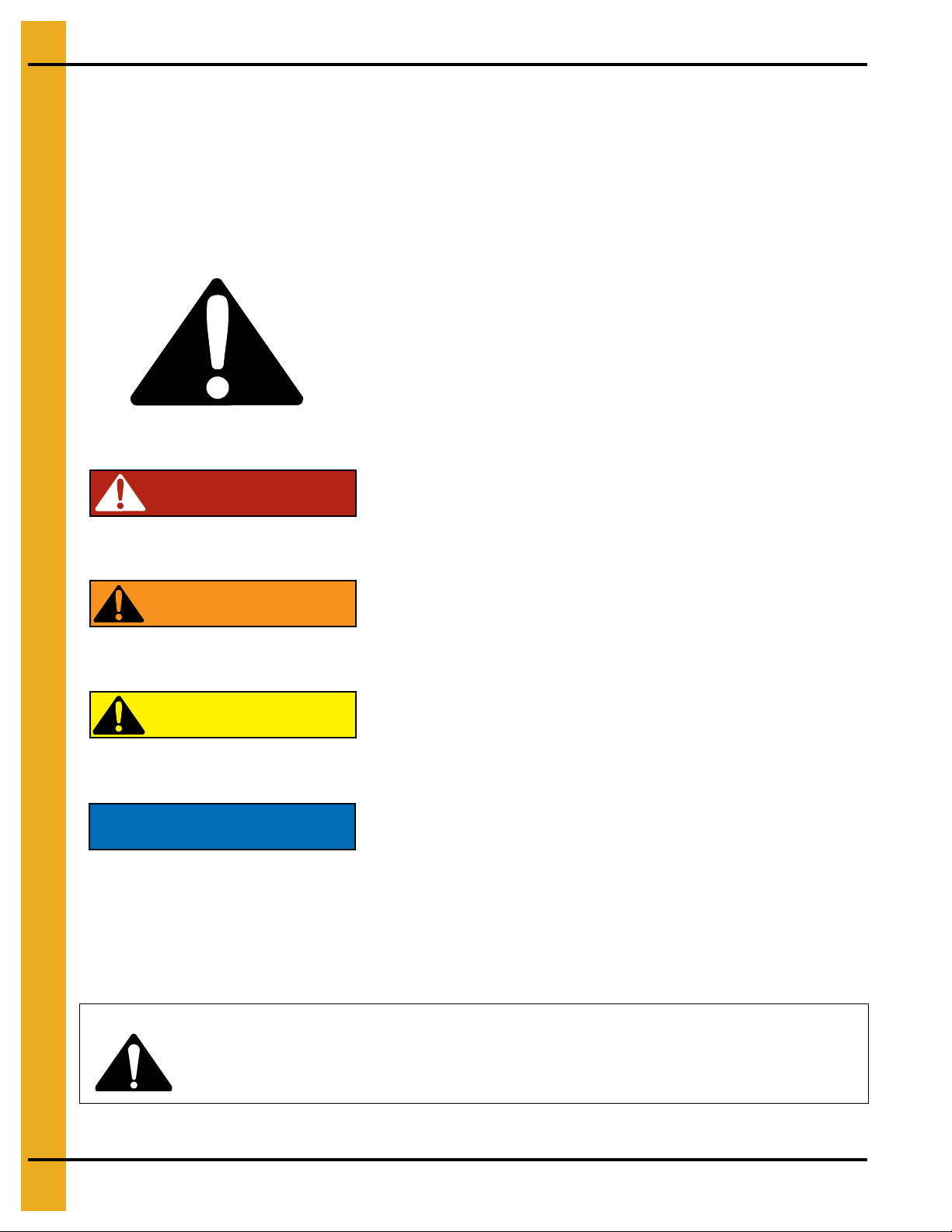
This is the safety alert symbol. It is used to alert you to
potential personal injury hazards. Obey all safety
messages that follow this symbol to avoid possible
injury or death.
WARNING indicates a potentially hazardous situation
which, if not avoided, could result in death or serious injury.
CAUTION indicates a potentially hazardous situation which,
if not avoided, may result in minor or moderate injury.
CAUTION used without the safety alert symbol indicates a
potentially hazardous situation which, if not avoided, may
result in property damage.
NOTE indicates information about the equipment that you
should pay special attention.
DANGER indicates an imminently hazardous situation
which, if not avoided, will result in death or serious injury.
Personnel operating or working around electric fans should read this manual. This manual
must be delivered with the equipment to its owner. Failure to read this manual and its
safety instructions is a misuse of the equipment.
WARNING! BE ALERT!
Safety Guidelines
This manual contains information that is important for you, the owner/operator, to know and understand.
This information relates to protecting personal safety and preventing equipment problems. It is the
responsibility of the owner/operator to inform anyone operating or working in the area of this equipment of
these safety guidelines. To help you recognize this information, we use the symbols that are defined
below. Please read the manual and pay attention to these sections. Failure to read this manual and its
safety instructions is a misuse of the equipment and may lead to serious injury or death.
DANGER
WARNING
CAUTION
NOTICE
8 PNEG-1702 ETL Listed GSI/FFI Portable Dryer Manual
Page 9
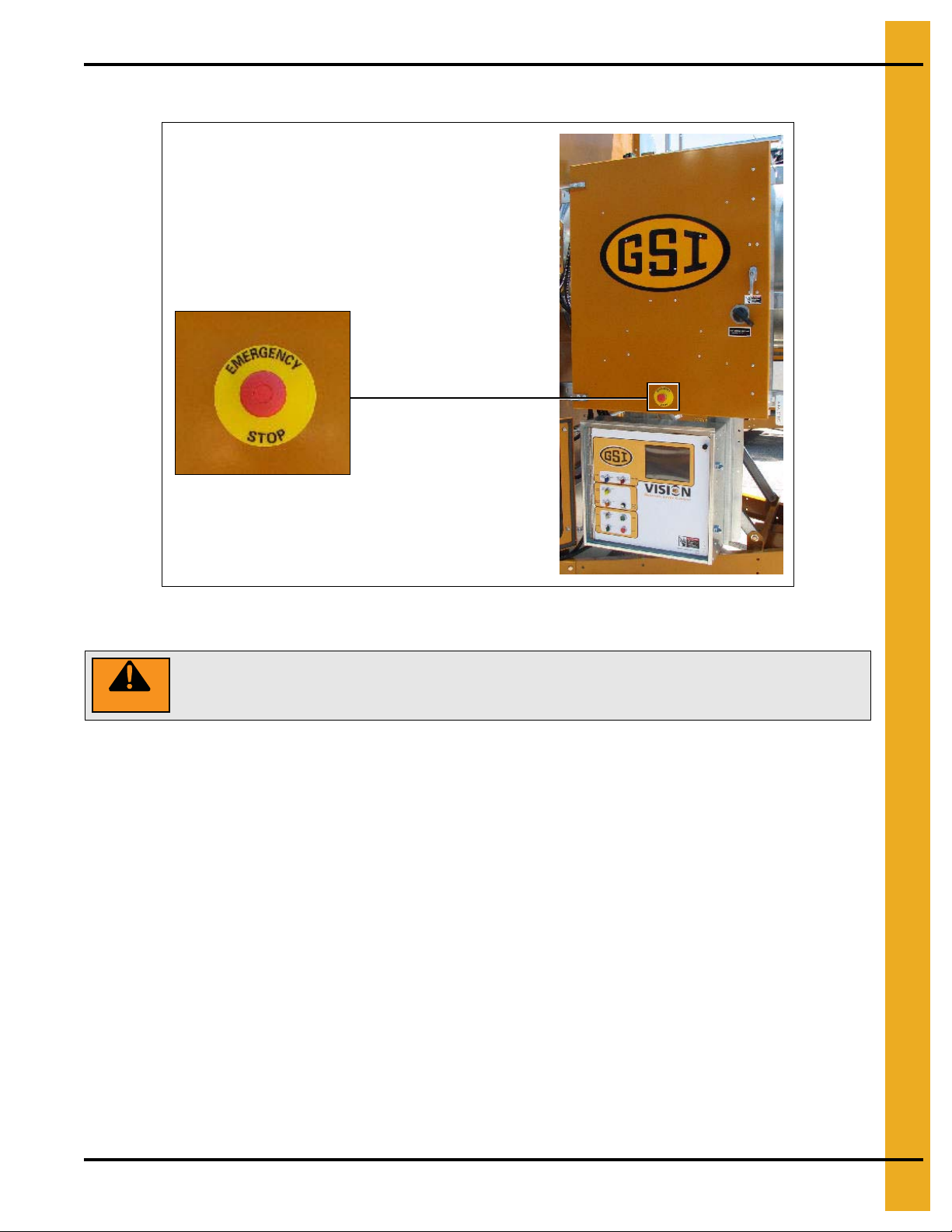
Emergency Stop Switch
WARNING
Pushing the Emergency Stop switch does not interrupt the main power to the
upper control box panel.
2. Safety
The Emergency Stop switch is located on the upper control box door. Pushing the Emergency Stop switch
will interrupt the control power and stop all dryer functions.
PNEG-1702 ETL Listed GSI/FFI Portable Dryer Manual 9
Page 10
3. Decals
DC-1948
Lockout power
before servicing.
Will cause serious
injury or death.
HIGH VOLTAGE.
Vérouillez le
courant avant
l’entretien.
Causera de
sérieuses blessures
ou la mort.
HAUTE TENSION
HIGH VOLTAGE.
Will cause injury
or death.
Lockout power
before servicing.
HAUTE TENSION.
Causera blessure
ou la mort.
Fermez le courant
avant l’entretien.
DC-1943
Decal: DC-1943
Decal DC-1943 has two (2)
locations. One inside the
fan/heater control box and
another on the dryer upper control
box door next to the main power
disconnect.
Decal: DC-1948
Decal DC-1948 is located in
two (2) places on the fan/heater
control box. One on the lid and
one on the front of the fan/heater
control box. Another location for
this decal is inside the upper
control box for the dryer.
GSI Group recommends contacting the local power company, and having a representative survey the
installation so the wiring is compatible with their system, and adequate power is supplied to the unit. Safety
decals should be read and understood by all people in the grain handling area.
If a decal is damaged or is missing, contact:
GSI Decals
1004 E. Illinois St.
Assumption, IL. 62510
Phone: 1-217-226-4421
A free replacement will be sent to you.
10 PNEG-1702 ETL Listed GSI/FFI Portable Dryer Manual
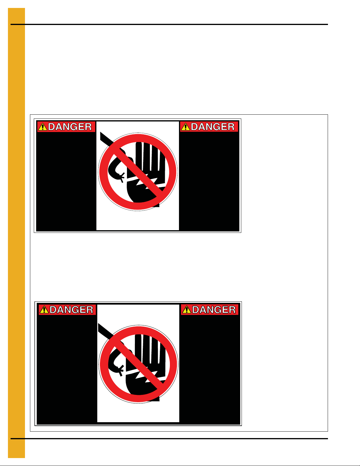
Page 11
Déplacer des pièces
peut écraser et couper.
Gardez les mains
éloignées. Ne pas faire
fonctionner sans avoir
de gardes en place.
L’omission de faire ceci
pourra résulter à de
sérieuses blessures.
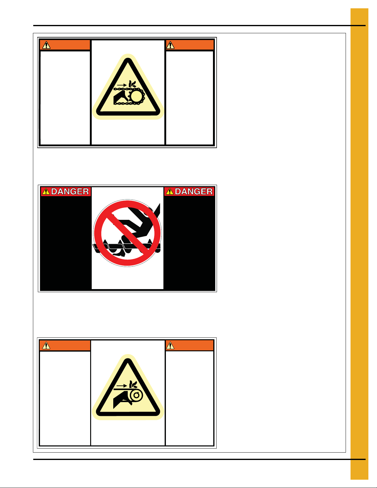
Moving parts can crush
and cut. Keep hands
clear. Do not operate
without guards in place.
Failure to do so could
result in serious injury.
WARNING
AVERTISSEMENT
DC-1945
Rotating auger will
crush and cut. Auto
equipment can start
at anytime. Do not
enter until electric
power is locked in off
position. Failure to do
so will result in
serious injury or
death.
La foreuse tournante
écrasera et coupera.
L’équipement
automatique peut se
mettre en marche en
tout temps. Ne pas
entrer tant que la
puissance
électrique ne soit
fermée à la position
‘arrêt’.
DC-1947
Automatically controlled
belt drive can start at
anytime. Keep hands
clear. Failure to do so
could result in serious
injury.
La conduite
automatiquement
contrôlée de la courroie
peut démarrer à tout
moment. Gardez les
mains éloignées.
L’omission de faire ceci
pourra résulter à de
sérieuses blessures.
WARNING
AVERTISSEMENT
DC-1944
Decal: DC-1945
Decal DC-1945 is located on the bottom auger
belt guard and the front bearing plate (which is
visible when the bottom auger belt guard is
removed). An alternate location would be at the
rear of the dryer for portable dryers equipped
with the Front Discharge Option.
Decal: DC-1944
Decal DC-1944 is located on the bottom auger
belt guard and the front bearing plate (which is
visible when the bottom auger belt guard is
removed). An alternate location would be at the
rear of the dryer for portable dryers equipped with
the
Front Discharge Option
. Another location
for decal DC-1944 is on the top of the auger belt
guard (one on the belt guard cover and one on
the inside belt guard body visible when the belt
guard cover is removed).
Decal: DC-1947
Decal DC-1947 has several different locations.
Two (2) are located on the front end panel
below the fan/heater. Two (2) are located on
the rear end panel below the rear access door.
Two (2) are located on the auger discharge box
(one on the outside top and one on the inside of
the flapper lid next to the discharge mercury
switch). One more of these decals is located
inside the plenum on the rear plenum closure
door just inside the rear access door.
3. Decals
PNEG-1702 ETL Listed GSI/FFI Portable Dryer Manual 11
Page 12
3. Decals
Automatic equipment
can start at anytime.
Do not enter until
fuel is shut off and
electrical power is
locked in off position.
Failure to do so will
result in serious
injury or death.
L’équipement
automatique peut se
mettre en marche en
tout temps. Ne pas
entrer tant que le
courant ne soit pas
coupé, et le courant
électrique fermé à la
position ‘arrêt’.
L’omission de faire
ceci pourra résulter à
de sérieuses
blessures ou la mort.
DC-1946
WARNING
AVERTISSEMENT
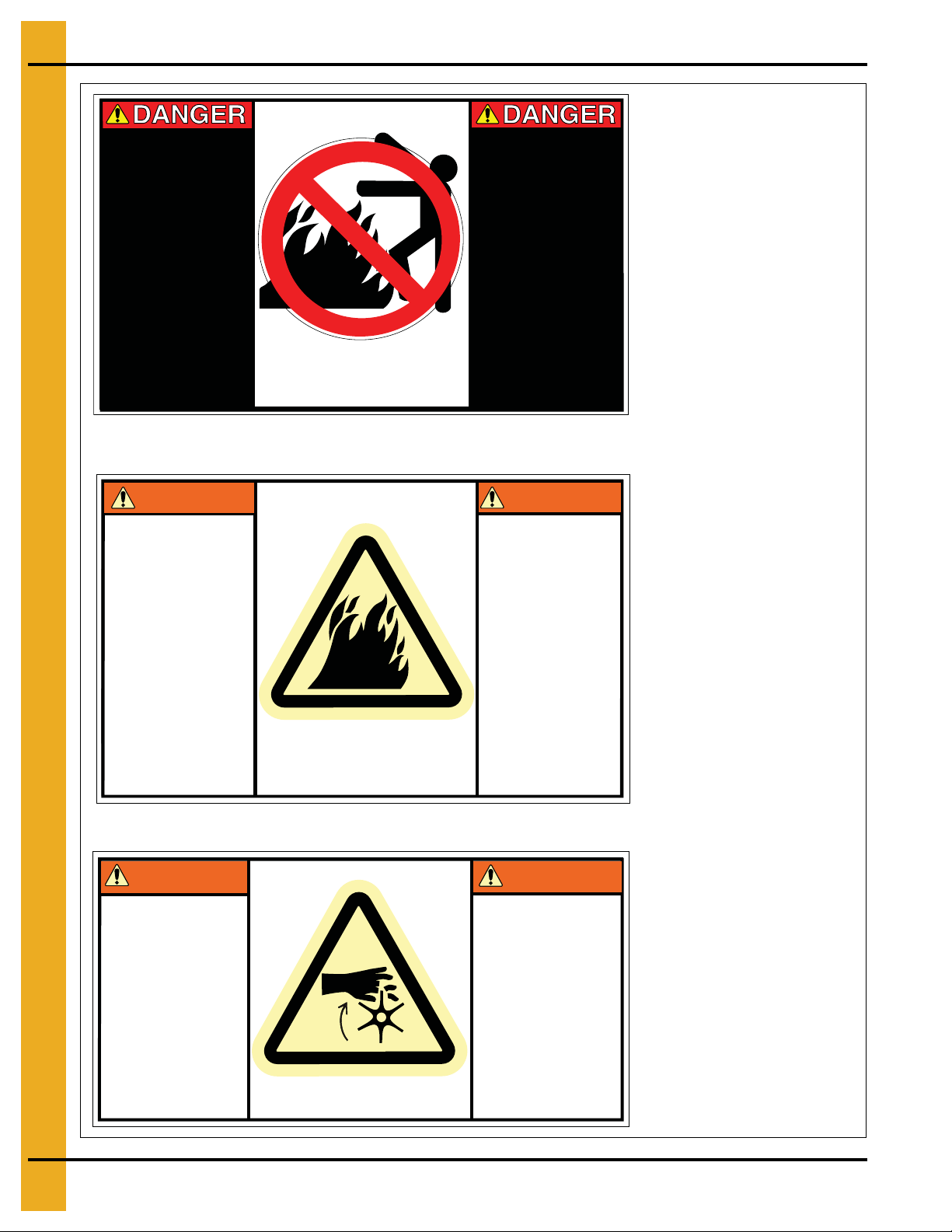
DC-1959
Flame and pressure
beyond door can
cause serious injury.
Do not operate with
service door removed.
Keep head and
hands clear.
La flamme et la
pression au-delà de la
porte peuvent causer
des dommages
sérieux. Ne pas faire
fonctionner si la porte
de service est
enlevée. Gardez les
mains et la tête
éloignés.
Decal: DC-1950
Decal DC-1950 is located on each
of the meter roll access doors.
Decal: DC-1946
Decal DC-1946 is located on the
rear plenum access door (inside
and outside).
Decal: DC-1959
Decal DC-1959 is located on
the fan/heater access door.
WARNING
Rotating metering roll.
Equipment can start
automatically. Keep
hands clear. Can cause
serious injury.
Disconnect power
before servicing.
AVERTISSEMENT
Compteur de roulement
tournant. L’équipement
automatique peut se
mettre en marche en
tout temps. - Gardez les
mains éloignées.
Débranchez le courant
avant l’entretien.
DC-1950
12 PNEG-1702 ETL Listed GSI/FFI Portable Dryer Manual
Page 13

3. Decals
Hitch pin must be
securely fastened and
no less than 3/4" in
diameter. Failure to
follow installation
instructions may result
in properly damage.
La goupille du crochet
doit être solidement
attachée et pas moins
de 3/4" de diamètre.
L’omission de suivre les
instructions d’installation
peut résulter à du
dommage de propriété.
DC-1954
ATTENTION CAUTION
3/4" MINIMUM
BOLT DIAMETER
SPEED
LIMIT
45
16-17"
Dryer must be towed
empty and in
accordance with
state and provincial
regulations.
Le séchoir doit être
remorqué vide et en
conformité avec les
réglements de l’état
et provinciaux.
HUB TEMPERATURE
TIGHTEN TO
90FT-LBS.
55-60 PSI COLD
CHECK AFTER 50 MILES AND EVERY 200 MILES
050
100
150
200 250
NO GREATER THAN 150°F
150°
DC-1956
ATTENTION CAUTION
Decal: DC-1954
Decal DC-1954 is located on the hitch tongue.
Decal: DC-1956
Decal DC-1956 is located on the hitch tongue.
Decal: DC-1949
Decal DC-1949 is located on
the fan/heater access door.
WARNING
Stay clear of rotating
blade. Blade could
start automatically.
Can cause serious
injury. Disconnect
power before
servicing.
AVERTISSEMENT
Restez éloigné de la
lame tournante. La
lame peut se mettre
en marche
automatiquement.
Peut causer de
sérieuses blessures.
Vérouillez le courant
avant l’entretien.
DC-1949
PNEG-1702 ETL Listed GSI/FFI Portable Dryer Manual 13
Page 14
4. Installation
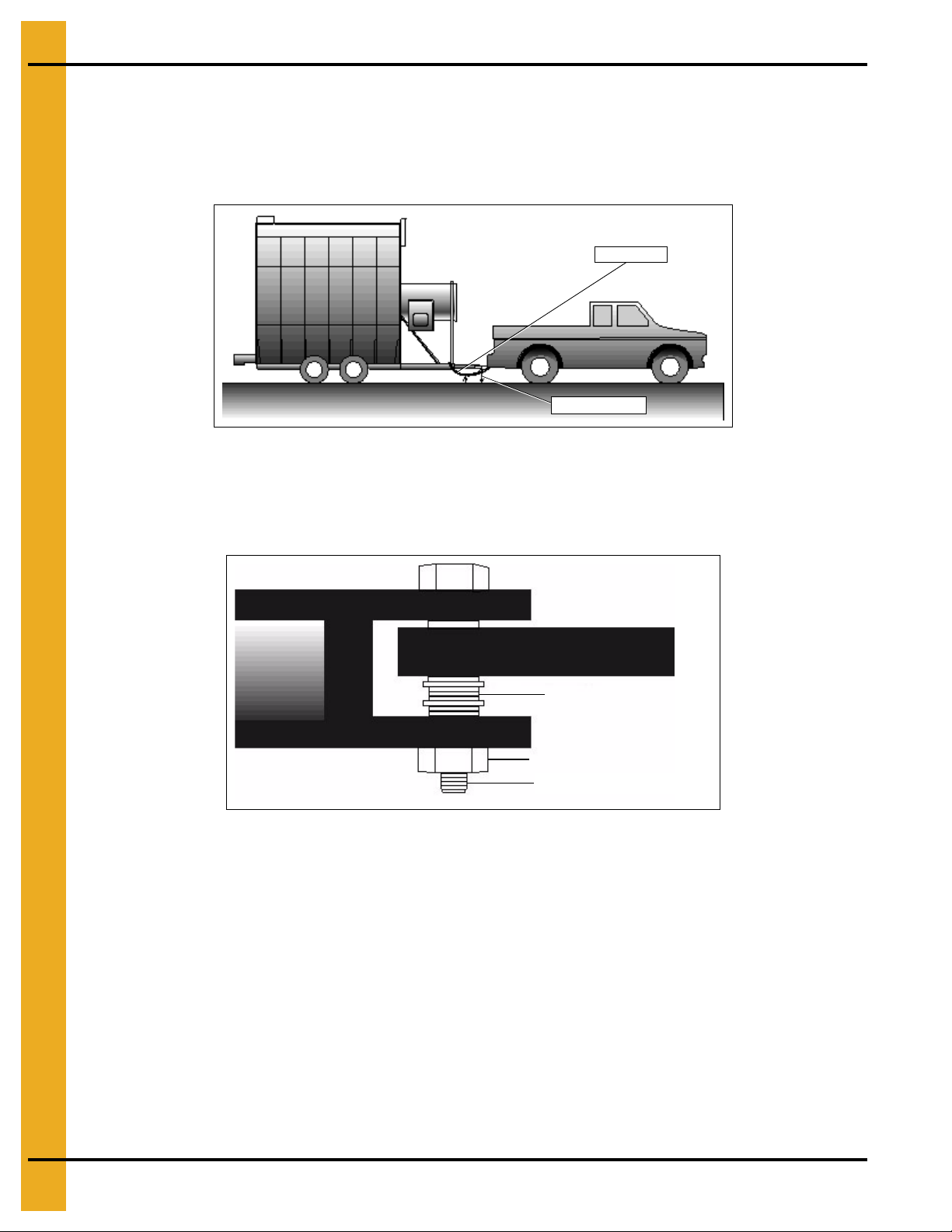
Tow chain
14"-17" Height
Washers
Locking nut
3/4" Minimum bolt diameter
Transporting/Single Fan
The dryer is available with an optional transport kit for transporting the unit by truck or tractor. Make certain
to observe the following safety precautions.
1. Recommended towing hitch height is 14"-17''. (See Figure 4A.)
Figure 4A Use a 14"-17'' Towing Hitch Height and a Safety Chain
2. Hitch bolt must be at least 3/4" in diameter and securely fastened with a locking nut, so it will not
come out during travel and the hitch will not bend. (See Figure 4B.)
3. Be sure to minimize vertical hitch play with washers. (See Figure 4B.)
Figure 4B A 3/4'' Hitch Bolt and Washers Fastened with a Locking Nut
at the Bottom of the Hitch
4. Always use a safety chain. (See Figure 4A.)
5. Dryer must be towed empty and in accordance with applicable state or provincial regulations.
NOTE: NEVER tow dryer with grain or any other material inside of it.
6. Recommended tire pressure is 55-60 PSI (cold).
7. Maximum towing speed is 45 miles per hour or the speed limit, whichever is lower.
8. After the first 50 miles and every 200 miles thereafter, check the following:
a. Dryer wheel hub and spindle temperature immediately after stopping. Temperature should not
exceed 150°F. It may be hot to touch, but not melting lubricant.
b. Wheel lug nuts. They are factory torqued at 115 to 120 ft. lbs. Retighten, if required.
14 PNEG-1702 ETL Listed GSI/FFI Portable Dryer Manual
Page 15

4. Installation
Location of the Dryer
When considering the exact location of the dryer, also consider the wet grain supply and dry grain
discharge, as well as the location of storage bins and other grain handling equipment. Do not install
the dryer inside a building or in any other area where not allowed by electrical codes, fuel installation
regulations and/or insurance requirements. Maintain a minimum distance of at least 3' from other
structures, otherwise air flow problems may occur. Do not operate in an area where combustible materials
can be drawn into the fans or where load and unload augers can come in contact with power lines.
Foundation
A reinforced concrete pad or similar permanent foundation is recommended for dryer stability.
See Pages 22 and 23 for details.
Supporting the Dryer
The wheels are to be used for transporting the dryer only when empty. Before loading any grain into the
dryer, the frame of the unit on each side must be supported. Place concrete blocks on each side, every
6' of the frame, as well as at the hitch mount location with the hitch removed. The blocks must be able to
support the dryer as well as the additional weight of the grain when full. Use shims to provide uniform, level
support for all blocks. The dryer should be at least 16'' off the pad to allow for clean out and the use of
auxiliary grain handling equipment. The hitch tongue should be removed, but the hitch assembly and the
fan support must be left on during operation; they are not part of the transport tie down assembly.
NOTE: Use a minimum of one support per each 6' of basket length on each side.
Anchor Points
Anchor points may be cast into the concrete slab or the dryer may be tied down by cables and turnbuckles
to anchors installed at the edge of the slab. This helps prevent overturn or lateral movement by wind or
other forces.
Wet/Dry Grain
Wet Grain Supply
A wet grain holding bin provides gravity flow to the dryer or loading conveyor. This conveyor may
be electrically connected to the power circuit provided in the main control box. Initially, the dryer will fill
completely. During drying, the top auger will start and stop as required depending upon the dry grain
discharge rate and grain shrinkage to maintain the dryer fill. If the dryer does not fill within the pre-set
time on the out of grain timer (See Vision Manual for instructions on setting this timer), the dryer
will shutdown.
Dry Grain Removal
The dry grain is normally discharged out of the rear end of the dryer. Front discharge is an optional feature.
A take away system needs to be provided to remove grain from the drying system. This conveyor may be
electrically connected to the power circuit provided in the main control box.
PNEG-1702 ETL Listed GSI/FFI Portable Dryer Manual 15
Page 16

4. Installation
Electrical Power Supply
Power Supply
An adequate power supply and proper wiring are important factors for maximum performance and long
life of the dryer. Electrical service must be adequate to prevent low voltage da mage to motors and control
circuits. (See Chapter 5 on Pages 24-36.) Power supply for 1 phase models must include a neutral wire.
Transformers and Wiring Voltage Drop
Advise the service representative of the local power supplier that an additional load will be placed on the
line. Check the KVA rating of transformers, considering total horsepower (HP) load. The power supply
wiring, main switch equipment and transformers must provide adequate motor starting and operating
voltage. Voltage drop during motor starting should not exceed 14% of normal voltage. After motor
is running at full speed, it should be within 8% of normal voltage. Check electrical load information
(See Chapter 5 on Pages 24-36)
Power Supply Disconnect
All dryers are equipped with a power disconnect switch in the power box to permit total power shutdown
before opening the power box door, as required for inspection and service. The power disconnect switch
is located on the power box door for quick shutdown.
for HP ratings and maximum amp loads.
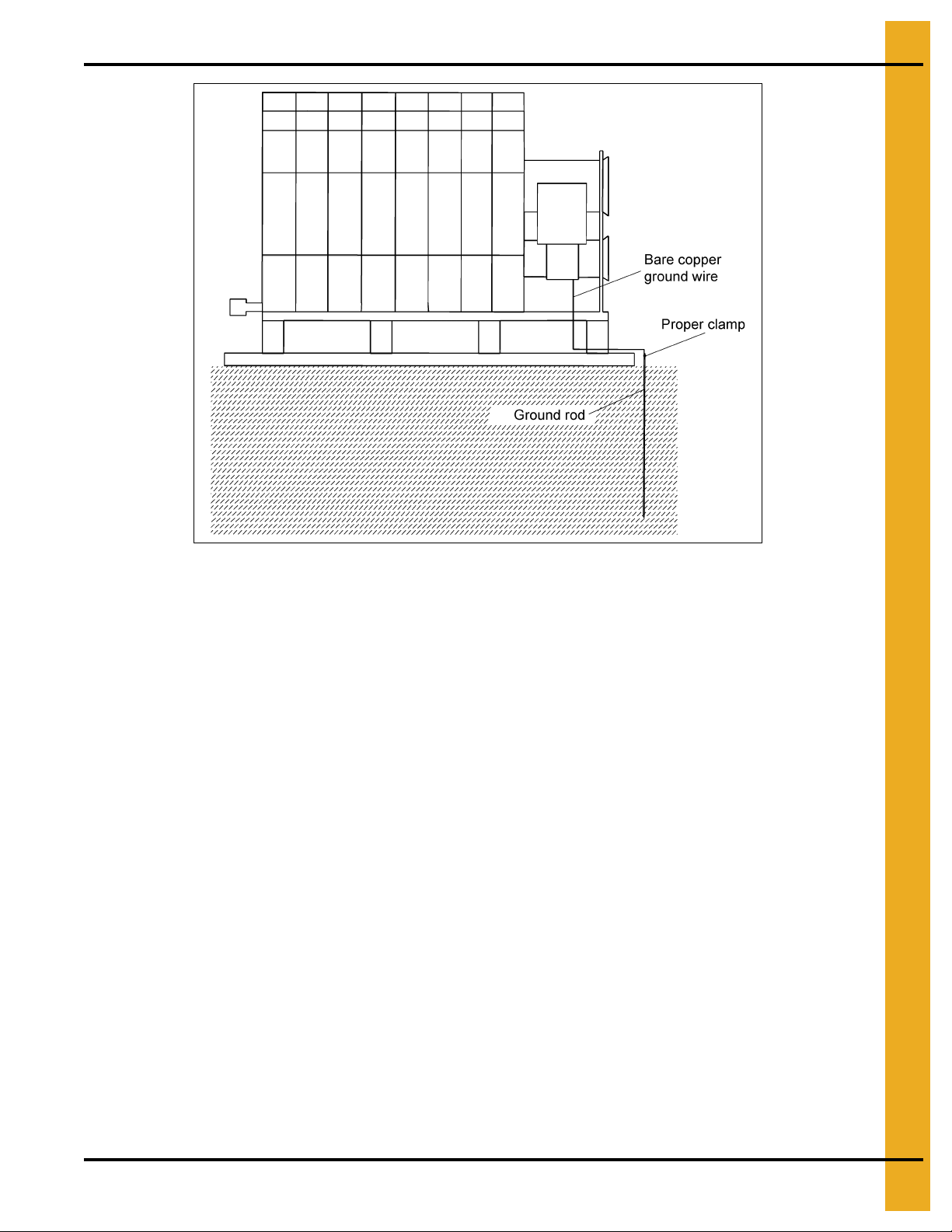
Machine to Earth Grounding
A Machine to Earth Ground Rod must be installed at the dryer. Place the ground rod that co mes standard
within 8' of the dryer and attach it to the dryer control panel with at least a #6 solid, bare, copper ground
wire and the clamp provided. The grounding rod located at the power pole will not provide adequate
grounding for the dryer. Proper grounding will provide additional safety in case of any short and will ensure
long life of all circuit boards, the SCR drive and the ignition system. The ground rod must be in accordance
with local requirements.
All wiring to be done in accordance with the Canadian Electrical Code.
16 PNEG-1702 ETL Listed GSI/FFI Portable Dryer Manual
Page 17
4. Installation
Figure 4C Installation of a ground rod (standard with dryer purchase) specifically
for the grain dryer is necessary for safety and equipment preservation.
Proper Installation of Ground Rod
The rod should not be driven into dry ground. Follow these instructions for proper installation.
1. Dig a hole large enough to hold one to two (2) gallons of water.
2. Fill hole with water.
3. Insert rod through water and “jab” it into the ground.
4. Continue “jabbing” the rod up and down. This allows the water to work its way into the ground,
allowing it to be completely inserted into the ground. This method of installation also assures good
contact with the surrounding soil, thereby making a proper ground.
5. Connect the bare, copper ground wire to the rod with the proper clamp.
6. Connect ground wire to control panel with the ground lug provided in the control box.
7. Ground wire must not have any breaks or splices. Do not use insulated wire for grounding ap plications.
Connecting Auxiliary Conveyors
The auxiliary load and auxiliary unload augers or conveyors can be wired directly to the dryer. Electrical
load information in Chapter 5 on Pages 24-36 shows the maximum horsepower and amps of auxiliaries
that can be wired to the dryer. If an auxiliary motor is larger than recommended, it must be powered from
a source outside the dryer and must use a separate contactor and overload protection device for each
motor. However, the operation of the auxiliaries can be performed by the control panel.
PNEG-1702 ETL Listed GSI/FFI Portable Dryer Manual 17
Page 18
4. Installation
See Fuel Specification
Chart on Page 19 for
recommended line use.
Fuel
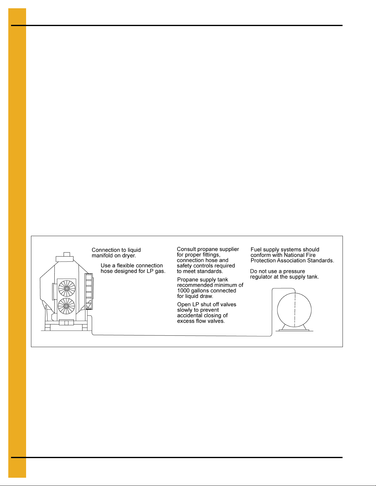
Liquid Propane (LP)
Liquid Draw
The dryers have internal vaporizers and are designed to operate on liquid draw from the supply tank. The
tank should be 1000 gallons or larger and should not have a regulator mounted to it. The connection to
the dryer should be with a flexible hose designed for LP gas, See Chart on Page 19 for proper size.
Consult your LP gas dealer for proper fittings, connection hose and safety controls required to meet local
standards and to conform with National Fire Protection Association standards. The piping train on the
dryer includes strainer, pressure relief valve, electronic safety shut off valve (on some models) and a
pressure regulator between the vaporizer and burner.
Ammonia Tanks
Do not use tanks which have previously been used for ammonia or fertilizer solutions. These substances
are extremely corrosive and will damage fuel supply and burner parts.
Oil or Water in Tanks
With liquid draw from the supply tank, any water or oil present in the tank may freeze in the pipe train or
controls causing damage. To make sure the tank is free of moisture, it can be purged with methanol.
Avoid tanks which may contain an accumulation of oil or heavy hydrocarbon from long use on a vapor
withdrawal system.
Figure 4D Grain dryer connected to a liquid propane tank.
“The equipment shall be installed in accordance with the current INSTALLATION CODES FOR GAS
BURNING APPLIANCES AND EQUIPMENT, CAN/CGA-B149.1 and CAN/CGA-B149.2, or applicable
provincial regulations, which should be carefully followed in all cases. Authorities having jurisdiction
should be consulted before installations are made”.
18 PNEG-1702 ETL Listed GSI/FFI Portable Dryer Manual
Page 19
4. Installation
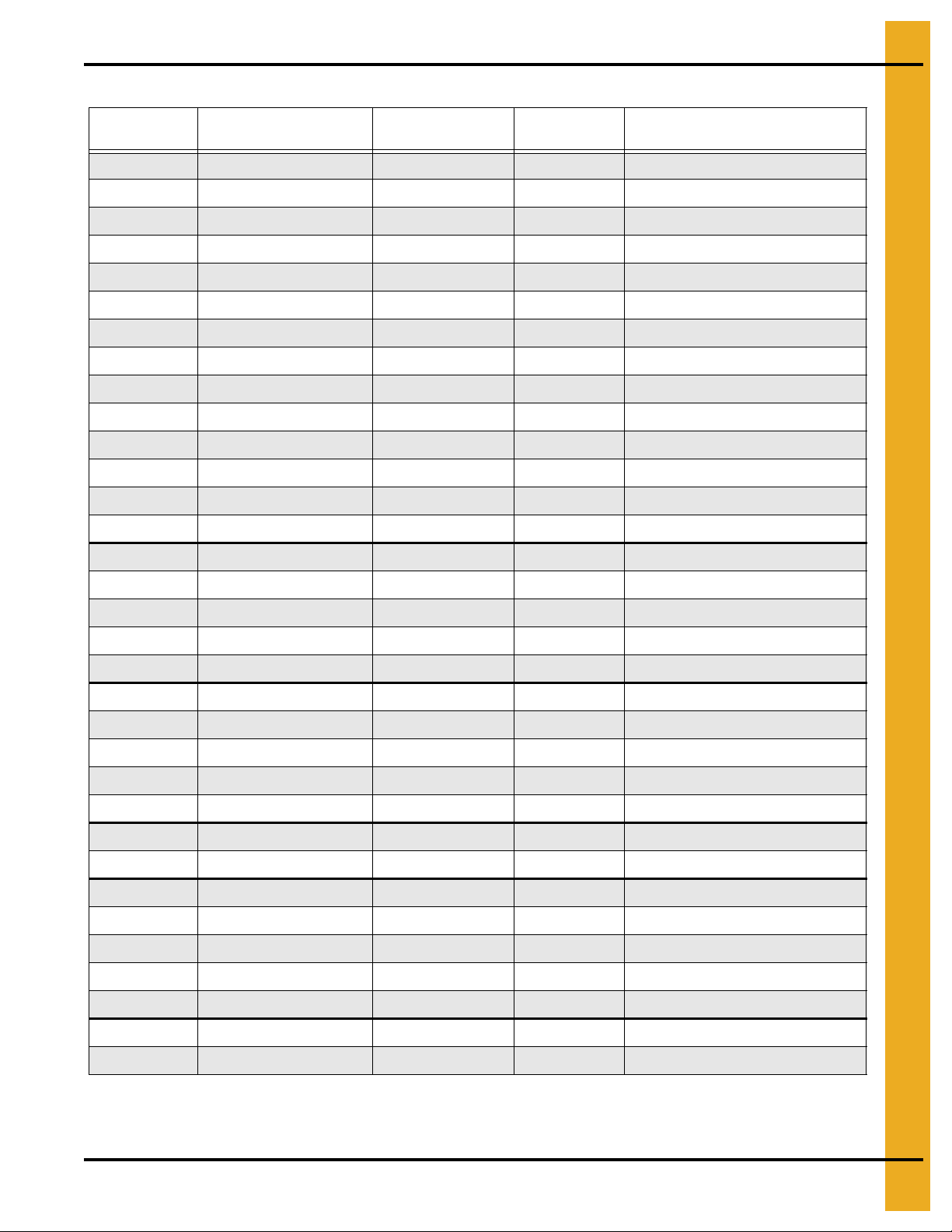
Fuel System Specifications and Recommendations (LP) Liquid Propane
Dryer
Model #
108/1108/190 3,500,000 38 1/2'' 1/4''
112/1112/270 4,500,000 49 1/2'' 21/64"
114/1114/320 5,750,000 63 1/2'' 11/32"
116/1116/370 5,750,000 63 1/2'' 11/32''
118/1118/400 7,000,000 76 1/2'' 3/8"
120/1120/460 7,500,000 82 1/2'' 25/64"
122/1122/511 8,500,000 93 3/4'' 7/16"
126/1126/601 9,500,000 104 3/4'' 29/64"
1214/2120 5,800,000 63 3/4'' (U)9/32" (L)7/32"
1216 6,800,000 74 3/4'' (U)21/64" (L)7/32"
1218/2125 6,800,000 74 3/4'' (U)21/64" (L)7/32"
1220/2130 8,750,000 96 3/4'' (U)11/32" (L)1/4"
1222 10,000,000 109 3/4'' (U)3/8" (L)1/4"
1226/2140 10,500,000 115 3/4'' (U)25/64" (L)1/4"
1214S/2141 7,000,000 76 3/4'' (2)-9/32"
Maximum Heat
Capacity BTU Per Hour
Maximum Fuel Flow
Gals Per Hour
Fuel Line Size* Heater Orifice Drill Size
1218S/2181 9,000,000 98 3/4'' (2)-21/64"
1220S/500H 11,500,000 126 3/4'' (2)-11/32"
1222S/2221 14,000,000 153 3/4'' (2)-3/8"
1226S/650M 15,000,000 164 3/4'' (2)-25/64"
2314/3142 11,750,000 128 3/4'' Top-11/32" Base (2)-1/4"
2318/3182 14,000,000 153 3/4'' Top-3/8" Base (2)-9/32"
2320/3202 16,500,000 180 3/4'' Top-25/64" Base (2)-21/64"
2322/3222 17,500,000 191 3/4'' Top-7/16" Base (2)-21/64"
2326/3262 24,500,000 267 3/4'' Top-29/64" Base (2)-23/64"
2420/1000H 18,000,000 197 3/4'' (4)-21/64"
2426/1300M 26,000,000 284 3/4'' (4)-23/64"
3414/4143 17,500,000 191 3/4'' Top-11/32" Mid-11/32" Base (2)-1/4"
3418/4183 21,000,000 229 3/4'' Top-3/8" Mid-3/8" Base (2)-9/32"
3420/4203 24,000,000 262 3/4'' Top-25/64" Mid-25/64" Base (2)-21/64"
3422/4223 26,000,000 284 3/4'' Top-7/16" Mid-7/16" Base (2)-21/64"
3426/4263 32,000,000 349 3/4'' Top-29/64" Mid-29/64" Base (2)-23/64"
3620/1500H 27,000,000 295 3/4'' (6)-21/64"
3626/2000M 39,000,000 426 3/4'' (6)-23/64"
* The minimum size of the fuel line for distances of 30.48 m (100').
PNEG-1702 ETL Listed GSI/FFI Portable Dryer Manual 19
Page 20
4. Installation
See Fuel Specifications Chart on
Page 21 for required pressure and
typical maximum fuel flow rates.
See Fuel Specifications Chart
on Page 21 for recommended
line size.
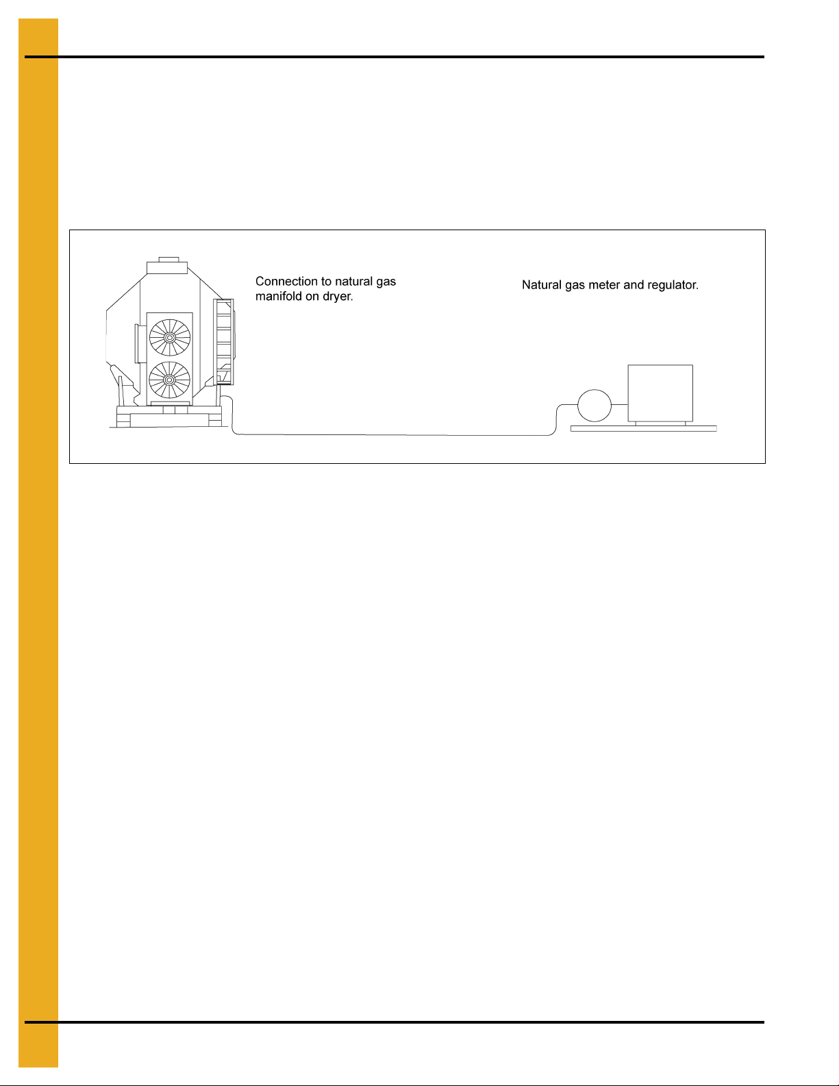
Natural Gas (NG)
Gas Volume and Pressure
The dryer is designed to operate on natural gas having a heat value of approximately 1000 BTU per cubic
foot. The dryer is equipped with a natural gas supply pipe system connected to the heater solenoid valves.
A regulated pressure of 10 PSI must be provided at the connection to the dryer, with gas available in
sufficient volume to maintain the operating pressure.
Figure 4E Grain dryer connected to a natural gas supply tank.
“The equipment shall be installed in accordance with the current INSTALLATION CODES FOR GAS
BURNING APPLIANCES AND EQUIPMENT, CAN/CGA-B149.1 and CAN/CGA-B149.2, or applicable
provincial regulations, which should be carefully followed in all cases. Authorities having jurisdiction
should be consulted before installations are made”.
20 PNEG-1702 ETL Listed GSI/FFI Portable Dryer Manual
Page 21

4. Installation
Fuel System Specifications and Recommendations (NG) Natural Gas
Dryer
Model #
108/1108/190 3,500,000 3500 1-1/2'' 3/8"
112/1112/270 4,500,000 4500 1-1/2'' 1/2"
114/1114/320 5,750,000 5750 1-1/2'' 33/64"
116/1116/370 5,750,000 5750 1-1/2'' 33/64"
118/1118/400 7,000,000 7000 2'' 35/64"
120/1120/460 7,500,000 7500 2'' 37/64"
122/1122/511 8,500,000 8500 2'' 19/32"
126/1126/601 9,500,000 9500 2'' 41/64"
1214/2120 5,800,000 5800 1-1/2'' (U)13/32" (L)5/16"
1216 6,800,000 6800 2'' (U)1/2" (L)5/16"
1218/2125 6,800,000 6800 2'' (U)1/2" (L)5/16"
1220/2130 8,750,000 8750 2'' (U)33/64" (L)5/16"
1222 10,000,000 10000 2'' (U)35/64" (L)5/16"
1226/2140 10,500,000 10500 2'' (U)37/64" (L)5/16"
1214S/2141 7,000,000 7000 1-1/2'' (2)-13/32"
Maximum Heat
Capacity BTU Per Hour
Maximum Fuel Flow
Cubic Feet Per Hour
Fuel Line Size* Heater Orifice Drill Size
1218S/2181 9,000,000 9000 1-1/2'' (2)-1/2"
1220S/500H 11,500,000 11500 2'' (2)-33/64"
1222S/2221 14,000,000 14000 2'' (2)-35/64"
1226S/650M 15,000,000 15000 2'' (2)-37/64"
2314/3142 11,750,000 11750 2'' Top-33/64" Base (2)-3/8"
2318/3182 14,000,000 14000 2'' Top-35/64" Base (2)-13/32"
2320/3202 16,500,000 16500 3'' Top-37/64" Base (2)-1/2"
2322/3222 17,500,000 17500 3'' Top-19/32" Base (2)-1/2"
2326/3262 24,500,000 24500 3'' Top-41/64" Base (2)-17/32"
2420/1000H 18,000,000 18000 3'' (4)-1/2"
2426/1300M 26,000,000 26000 3'' (4)-17/32"
3414/4143 17,500,000 17500 3'' Top-33/64" Mid-33/64" Base (2)-3/8"
3418/4183 21,000,000 21000 3'' Top-35/64" Mid-35/64" Base (2)-13/32"
3420/4203 24,000,000 24000 3'' Top-37/64" Mid-37/64" Base (2)-1/2"
3422/4223 26,000,000 26000 3'' Top-19/32" Mid-19/32" Base (2)-1/2"
3426/4263 32,000,000 32000 3'' Top-41/64" Mid-41/64" Base (2)-17/32"
3620/1500H 27,000,000 27000 3'' (6)-1/2"
3626/2000M 39,000,000 39000 3'' (6)-17/32"
* The minimum size of the fuel line for distances of 30.48 m (100').
PNEG-1702 ETL Listed GSI/FFI Portable Dryer Manual 21
Page 22
4. Installation
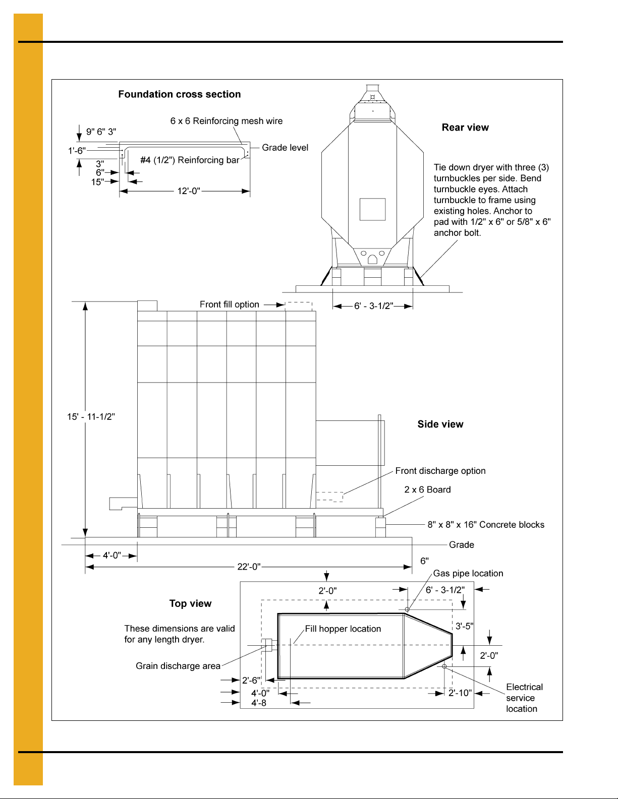
Single Fan Foundation
Figure 4F
22 PNEG-1702 ETL Listed GSI/FFI Portable Dryer Manual
Page 23
4. Installation
Minimum Bag Mix for Concrete Strength per Model Weight
Dryer Basket Length 6 8 10 12 14 16 18 20 22 26
Concrete Pad Size 12 x 16 12 x 18 12 x 20 12 x 22 12 x 24 12 x 26 12 x 28 12 x 30 12 x 32 12 x 36
Yards Concrete 5.3 5.9 6.5 7.1 7.7 8.3 8.9 9.2 10.1 11.3
Reinforcing Rods 20" each
Wire Mesh Sq. Ft. 192 216 240 264 288 312 336 360 384 432
Steel Legs (Minimum) 8 8 10 10 12 12 14 14 16 18
Anchors 4 4 4 6 6 6 8 8 8 10
Blocks 10 14 14 18 18 18 22 22 26 30
Foot of 2 x 6 10 14 14 18 18 18 22 22 26 30
Turnbuckles 4 4 4 6 6 6 8 8 8 10
Estimated Man Hours 8 10 12 14 18 18 20 22 24 28
Quantities are approximate and requirements may vary due to site elevations.
Setup times do not include site preparation and pouring concrete pad.
6 6 7 7 7 8 8 8 9 10
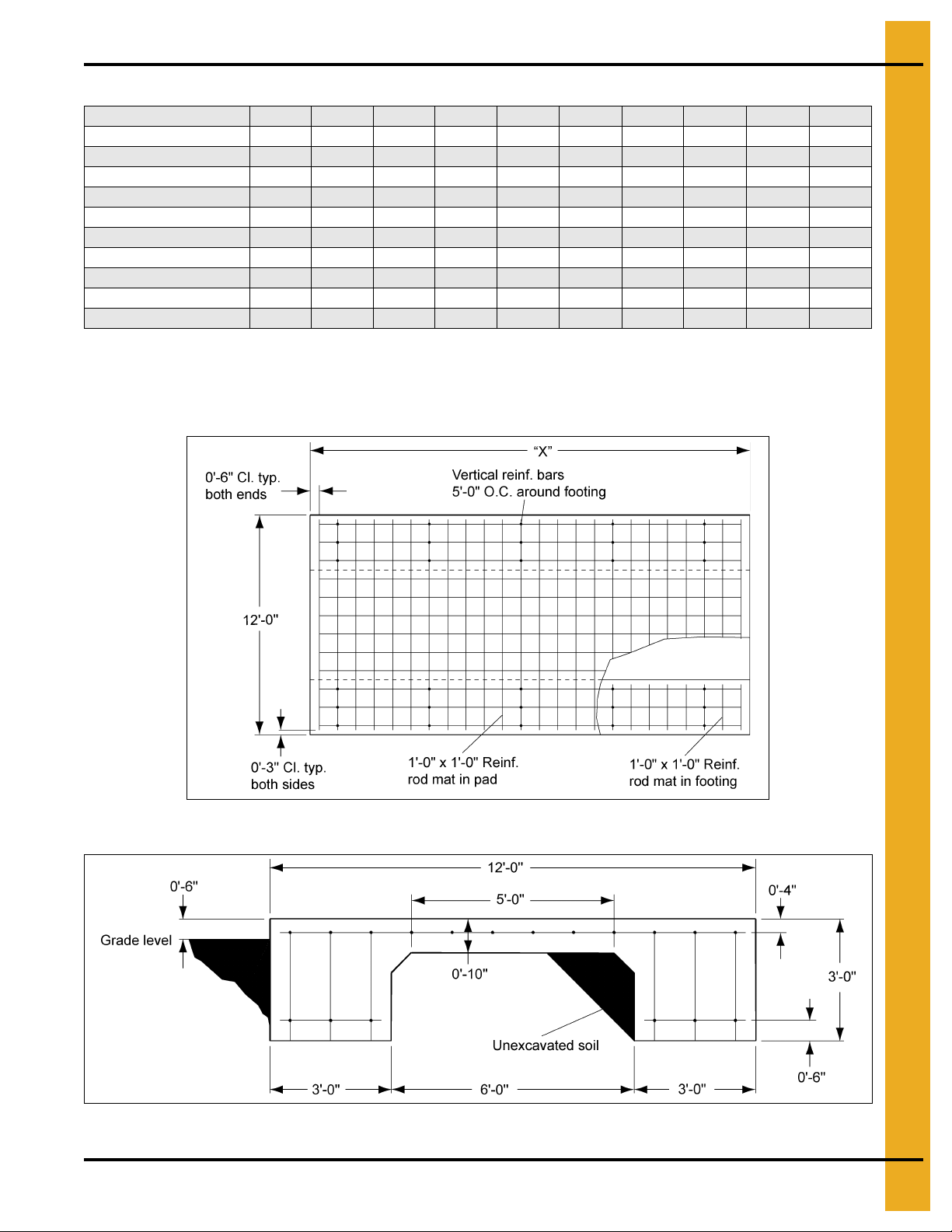
All Stack Dimensions
Figure 4G Foundation Plan View
Figure 4H Foundation Cross Section
PNEG-1702 ETL Listed GSI/FFI Portable Dryer Manual 23
Page 24
5. Specifications
FFI Dimensions
Figure 5A
Figure 5B
24 PNEG-1702 ETL Listed GSI/FFI Portable Dryer Manual
Page 25
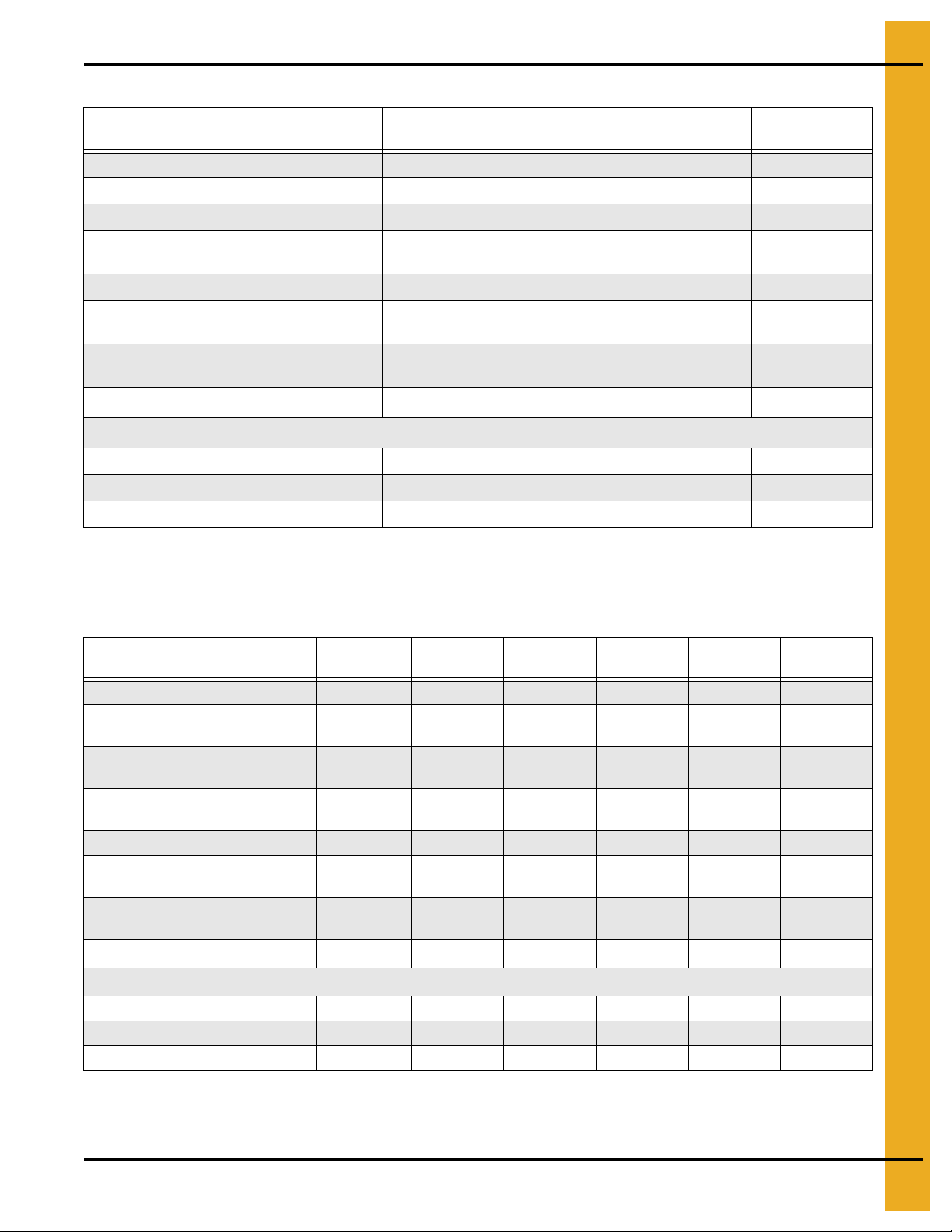
Single Module FFI Transport and Installation Dimensions
Values are Valid for Transportation of Stack Modules
AB C DE F G H
5. Specifications
1 Fan CFAB
Series Dryers
2 Fan CFAB
Series Dryers
Dryer
Basket
190T (8') 11' 11" 8' 13' 11' 6" 10' 3" 6' 5" 8' 17' 2" 19' 2"
270 (12') 13' 5" 8' 14' 6" 13' 11' 9" 6' 5" 8' 19' 2" 21' 2"
320 (14') 13' 5" 8' 14' 6" 13' 11' 9" 6' 5" 8' 21' 2" 23' 2"
370 (16') 13' 5" 8' 14' 6" 13' 11' 9" 6' 5" 8' 23' 2" 25' 2"
400 (18') 13' 5" 8' 14' 6" 13' 11' 9" 6' 5" 8' 25' 2" 27' 2"
460 (20') 13' 5" 8' 14' 6" 13' 11' 9" 6' 5" 8' 27' 2" 29' 2"
511 (22') 13' 5" 8' 14' 6" 13' 11' 9" 6' 5" 8' 29' 2" 31' 2"
601 (26') 13' 5" 8' 14' 6" 13' 11' 9" 6' 5" 8' 33' 2" 35' 2"
320 (14') 13' 5" 8' 8" 14' 6" 13' 11' 9" 6' 5" 8' 21' 2" 23' 2"
410 (18') 13' 5" 8' 8" 14' 6" 13' 11' 9" 6' 5" 8' 25' 2" 27' 2"
510 (22') 13' 5" 8' 8" 14' 6" 13' 11' 9" 6' 5" 8' 29' 2" 31' 2"
600 (26') 13' 5" 8' 8" 14' 6" 13' 11' 9" 6' 5" 8' 33' 2" 35' 2"
2120 (14') 13' 5" 8' 14' 6" 13' 11' 9" 6' 5" 8' 21' 2" 23' 2"
Transport
Height
Installed
Width
Installed Height
Standard
Bin
Top
Height
w/o Wet
Bin
Frame
Width
Transport
Width
Installed
Length
Transport
LengthWet
C2100A
Series Dryers
2122 (16') 13' 5" 8' 14' 6" 13' 11' 9" 6' 5" 8' 23' 2" 25' 2"
2125 (18') 13' 5" 8' 14' 6" 13' 11' 9" 6' 5" 8' 25' 2" 27' 2"
2130 (20') 13' 5" 8' 14' 6" 13' 11' 9" 6' 5" 8' 27' 2" 29' 2"
2132 (22') 13' 5" 8' 14' 6" 13' 11' 9" 6' 5" 8' 29' 2" 31' 2"
2140 (26') 13' 5" 8' 14' 6" 13' 11' 9" 6' 5" 8' 33' 2" 35' 2"
PNEG-1702 ETL Listed GSI/FFI Portable Dryer Manual 25
Page 26
5. Specifications
1 Fan CFAB profile
2 Fan CFAB profil e
C2100A profile
FFI Specifications
Figure 5C
1 Fan CFAB Specifications
CFAB 190 8'CFAB 270
Total Holding Capacity (Bushels) 216 294 357 436 509 565 622 735
Grain Column Holding Capacity (Bushels) 186 25 7 300 376 414 460 506 598
Fan
Top Auger
Capacity (BHP) 925 1150 1800 2800 2800 2800 2800 2800
Bottom Auger
Meter Roll Drive
Capacity - Maximum Rate1 (BHP)
Electrical Load (Fans, Top and Bottom Augers2)
1 Phase, 220 Volt 77 96 100 108 - - - -
36"
10-13 HP
8" Dia.
2 HP
8" Dia.
1.5 HP
SCR,
3/4 HP
1120 1680 1960 2240 2520 2800 3080 3640
12'
36"
15 HP
8" Dia.
2 HP
8" Dia.
2 HP
SCR,
3/4 HP
CFAB 320
14'
40"
15 HP
8" Dia.
5 HP
8" Dia.
3 HP
SCR,
3/4 HP
CFAB 370
16'
40"
15 HP
8" Dia.
5 HP
8" Dia.
3 HP
SCR,
3/4 HP
CFAB 400
18'
42"
20 HP
8" Dia.
5 HP
8" Dia.
3 HP
SCR,
3/4 HP
CFAB 460
20'
42"
25 HP
8" Dia.
7.5 HP
8" Dia.
5 HP
SCR,
3/4 HP
CFAB 511
22'
42"
30 HP
8" Dia.
7.5 HP
8" Dia.
5 HP
SCR,
3/4 HP
CFAB 601
26'
42"
40 HP
8" Dia.
10 HP
8" Dia.
7.5 HP
SCR,
3/4 HP
3 Phase, 220 Volt 44 52 56 65 95 107 114 150
3 Phase, 440 Volt 22 26 28 33 46 53 57 75
1
Actual discharge rate is controlled by meter roll speed adjustment, at 5% to 100% of maximum rate.
2
Excludes auxiliary load and unload conveyor equipment.
26 PNEG-1702 ETL Listed GSI/FFI Portable Dryer Manual
Page 27
2 Fan CFAB Specifications
5. Specifications
CFSA 320
14'
CFSA 410
18'
CFSA 510
22'
CFSA 600
26'
Total Holding Capacity (Bushels) 357 459 622 735
Grain Column Holding Capacity (Bushels) 300 386 506 598
Fans 28" 10-13 HP (2) 28" 10-13 HP (2) 36" 15 HP (2) 39" 20 HP (2)
Top Auger
8" Dia.
5 HP
8" Dia.
5 HP
8" Dia.
7.5 HP
8" Dia.
10 HP
Capacity (BHP) 1800 1800 2800 2800
Bottom Auger
Meter Roll Drive
Capacity - Maximum Rate
1
(BHP)
8" Dia.
3 HP
SCR,
3/4 HP
1960 2520 3080 3640
8" Dia.
3 HP
SCR,
3/4 HP
8" Dia.
5 HP
SCR,
3/4 HP
8" Dia.
7.5 HP
SCR,
3/4 HP
Electrical Load (Fans, Top and Bottom Augers2)
1 Phase, 220 Volt 136 156 217 3 Phase, 220 Volt 72 92 127 166
3 Phase, 440 Volt 36 46 63 83
1
Actual discharge rate is controlled by meter roll speed adjustment, at 5% to 100% of maximum rate.
2
Excludes auxiliary load and unload conveyor equipment.
C2100A Specifications
C2120A
14'
Total Holding Capacity (Bushels) 375 436 490 544 599 708
Grain Column Holding Capacity
(Bushels)
Fans
Top Auger
322 376 415 460 517 600
28" 10-13 HP/
28" 10-13 HP
8" Dia.
5 HP
Capacity (BHP) 1800 2800 2800 2800 2800 2800
Bottom Auger
Meter Roll Drive
Capacity - Maximum Rate
1
(BHP)
8" Dia.
3 HP
SCR,
3/4 HP
1960 2240 2520 2800 3080 3640
Electrical Load (Fans, Top and Bottom Augers2)
1 Phase, 220 Volt 146 187 187 - - 3 Phase, 220 Volt 92 96 96 135 144 154
3 Phase, 440 Volt 46 48 48 68 72 77
1
Actual discharge rate is controlled by meter roll speed adjustment, at 5% to 100% of maximum rate.
C2122A
16'
28" 10-13 HP/
36" 15 HP
8" Dia.
5 HP
8" Dia.
3 HP
SCR,
3/4 HP
C2125A
18'
28" 10-13 HP/
36" 15 HP
8" Dia.
5 HP
8" Dia.
3 HP
SCR,
3/4 HP
C2130A
20'
28" 10-13 HP/
39" 20 HP
8" Dia.
7.5 HP
8" Dia.
5 HP
SCR,
3/4 HP
C2132A
22'
28" 10-13 HP/
42" 20 HP
8" Dia.
7.5 HP
8" Dia.
5 HP
SCR,
3/4 HP
C2140A
26'
28" 10-13 HP/
42" 25 HP
8" Dia.
10 HP
8" Dia.
7.5 HP
SCR,
3/4 HP
2
Excludes auxiliary load and unload conveyor equipment.
PNEG-1702 ETL Listed GSI/FFI Portable Dryer Manual 27
Page 28

5. Specifications
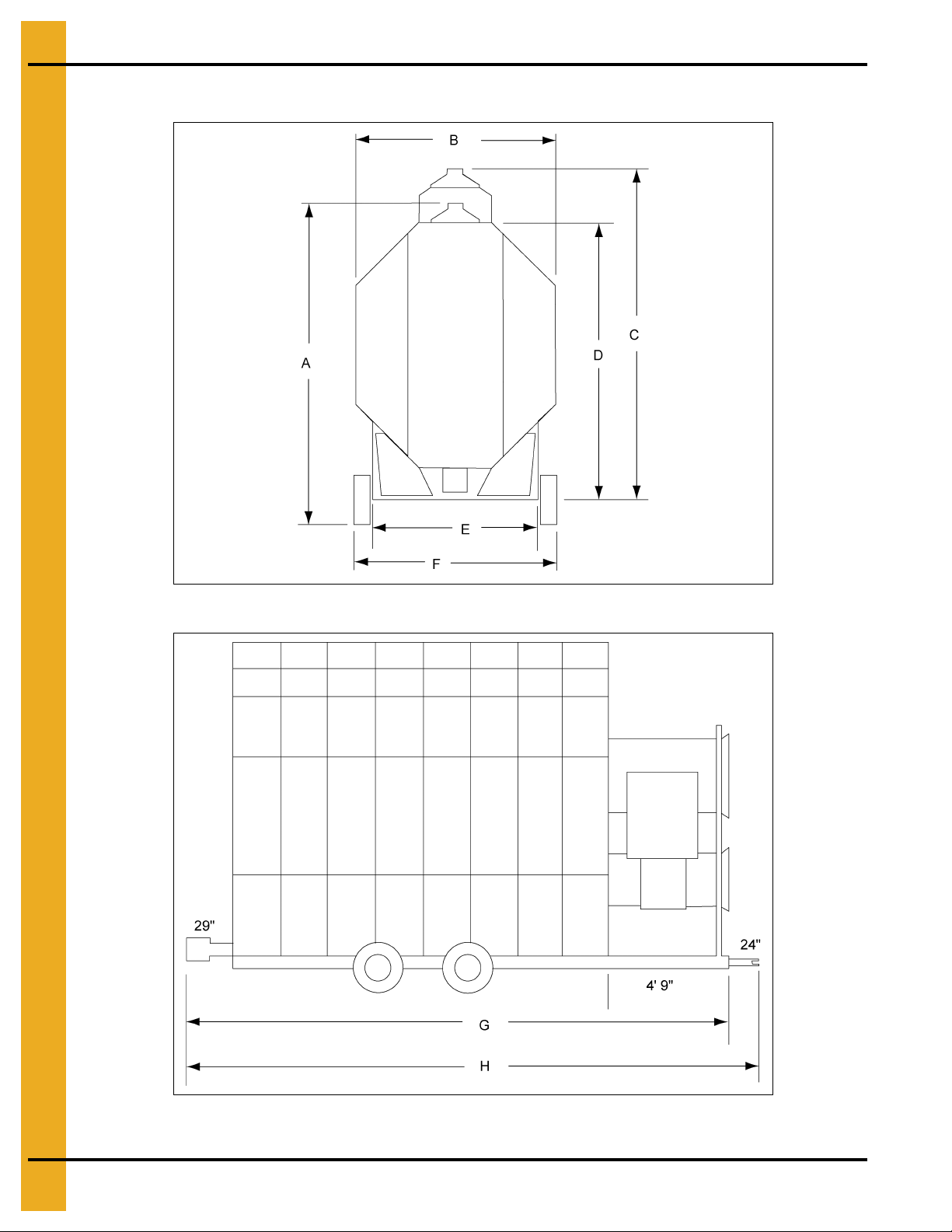
GSI Dimensions
Figure 5D
Figure 5E
28 PNEG-1702 ETL Listed GSI/FFI Portable Dryer Manual
Page 29
5. Specifications
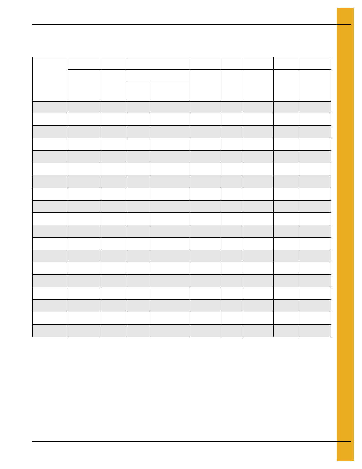
Single Module GSI Transport and Installation Dimensions
Values are Valid for Transportation of Stack Modules
AB C DEFGH
Dryer
Basket
1108T/108T 13' 5'' 8' 14' 6'' 13' 11' 9' ' 6' 5'' 8' 15' 2'' 17' 2''
1112/112 13' 5'' 8' 14' 6'' 13' 11' 9'' 6' 5'' 8' 19' 2'' 21' 2''
1114/114 13' 5'' 8' 14' 6'' 13' 11' 9'' 6' 5'' 8' 21' 2'' 23' 2''
1116/116 13' 5'' 8' 14' 6'' 13' 11' 9'' 6' 5'' 8' 23' 2'' 25' 2''
1118/118 13' 5'' 8' 14' 6'' 13' 11' 9'' 6' 5'' 8' 25' 2'' 27' 2''
1120/120 13' 5'' 8' 14' 6'' 13' 11' 9'' 6' 5'' 8' 27' 2'' 29' 2''
1 122/122 13' 5'' 8' 14' 6'' 13' 11' 9'' 6' 5'' 8' 29' 2'' 31' 2''
1126/126 13' 5'' 8' 14' 6'' 13' 11' 9'' 6' 5'' 8' 33' 2'' 35' 2''
1214 13' 5'' 8' 14' 6'' 13' 11' 9'' 6' 5' ' 8' 21' 2'' 23' 2''
1216 13' 5'' 8' 14' 6'' 13' 11' 9'' 6' 5'' 8' 23' 2'' 25' 2''
1218 13' 5'' 8' 14' 6'' 13' 11' 9'' 6' 5' ' 8' 25' 2'' 27' 2''
1220 13' 5'' 8' 14' 6'' 13' 11' 9'' 6' 5'' 8' 27' 2'' 29' 2''
Transport
Height
Installed
Width
Installed Height
Wet Bin
Standard
Top
Height w/o
Wet Bin
Frame
Width
Trans-
port
Width
Installed
Length
Transport
Length
1222 13' 5'' 8' 14' 6'' 13' 11' 9'' 6' 5' ' 8' 29' 2'' 31' 2''
1226 13' 5'' 8' 14' 6'' 13' 11' 9'' 6' 5'' 8' 33' 2'' 35' 2''
1214S 13' 5'' 8' 8'' 14' 6'' 13' 11' 9'' 6' 5'' 8' 21' 2'' 23' 2''
1218S 13' 5'' 8' 8'' 14' 6'' 13' 11' 9'' 6' 5'' 8' 25' 2'' 27' 2''
1220S 13' 5'' 8' 8'' 14' 6'' 13' 11' 9'' 6' 5'' 8' 27' 2'' 29' 2''
1222S 13' 5'' 8' 8'' 14' 6'' 13' 11' 9'' 6' 5'' 8' 29' 2'' 31' 2''
1226S 13' 5'' 8' 8'' 14' 6'' 13' 11' 9'' 6' 5'' 8' 33' 2'' 35' 2''
PNEG-1702 ETL Listed GSI/FFI Portable Dryer Manual 29
Page 30
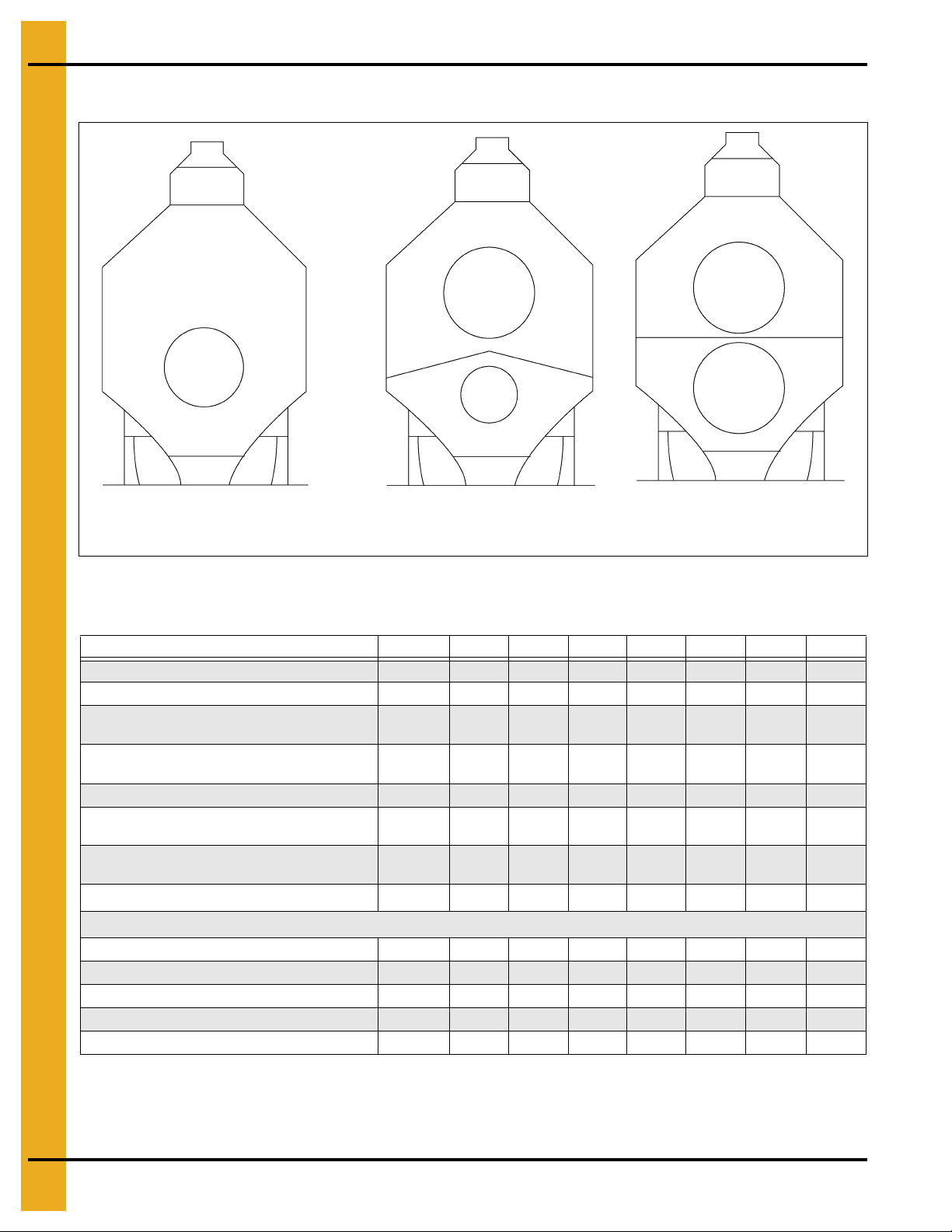
5. Specifications
1100 Series profile
1200 Series profile
1200S Series profile
GSI Specifications
Figure 5F
1100 Series Dryer Specifications
1108T/108 1112/112 1114/114 1116/116 1118/118 1120/120 1122/122 1126/126
Total Holding Capacity (Bushels) 190 327 381 436 490 544 599 708
Grain Column Holding Capacity (Bushels) 160 282 329 376 423 470 517 611
Fan
Top Auger
Capacity (BHP) 2900 2900 3800 3800 3800 3800 3800 3800
Bottom Auger
Meter Roll Drive
1
Capacity - Maximum Rate
Electrical Load (Fans, Top and Bottom Augers2)
1 Phase, 220 Volt 63 85 98 108 - - - 3 Phase, 220 Volt 42 50 56 65 80 104 114 150
3 Phase, 440 Volt 21 25 28 33 40 52 57 75
3 Phase, 575 Volt 18 20 23 27 32 42 46 61
3 Phase, 380 Volt 22 33 36 44 49 68 75 88
1
Actual discharge rate is controlled by meter roll speed adjustment, at 5% to 100% of maximum rate.
2
Excludes auxiliary load and unload conveyor equipment.
(BHP)
36''
10-13 HP
8'' Dia.
2 HP
8'' Dia.
1-1/2 HP
SCR,
3/4 HP
1120 1680 1960 2240 2520 2800 3080 3640
36''
15 HP
8'' Dia.
2 HP
8'' Dia.
1-1/2 HP
SCR,
3/4 HP
40''
15 HP
8'' Dia.
5 HP
8'' Dia.
3 HP
SCR,
3/4 HP
40''
15 HP
8'' Dia.
5 HP
8'' Dia.
5 HP
SCR,
3/4 HP
42''
20 HP
8'' Dia.
5 HP
8'' Dia.
5 HP
SCR,
3/4 HP
42''
25 HP
8'' Dia.
7-1/2 HP
8'' Dia.
7-1/2 HP
SCR,
3/4 HP
42''
30 HP
8'' Dia.
7-1/2 HP
8'' Dia.
7-1/2 HP
SCR,
3/4 HP
42''
40 HP
8'' Dia.
10 HP
8'' Dia.
10 HP
SCR,
3/4 HP
30 PNEG-1702 ETL Listed GSI/FFI Portable Dryer Manual
Page 31

5. Specifications
1200 Series Dryer Specifications
1214 1216 1218 1220 1222 1226
Total Holding Capacity (Bushels) 381 436 490 544 599 708
Grain Column Holding
Capacity (Bushels)
Fan
Top Auger
Capacity (BHP) 3800 3800 3800 3800 3800 3800
Bottom Auger
Meter Roll Drive SCR, 3/4 HP SCR, 3/4 HP SCR, 3/4 HP SCR, 3/4 HP SCR, 3/4 HP SCR, 3/4 HP
1
Capacity - Maximum Rate
(BHP)
Electrical Load (Fans, Top and Bottom Augers2)
1 Phase, 220 Volt 142 156 156 172 - 3 Phase, 220 Volt 92 99 99 112 126 150
3 Phase, 440 Volt 47 50 50 57 63 75
3 Phase, 575 Volt 37 42 42 47 52 61
3 Phase, 380 Volt 50 61 61 70 75 90
1
Actual discharge rate is controlled by meter roll speed adjustment, at 5% to 100% of maximum rate.
2
Excludes auxiliary load and unload conveyor equipment.
329 376 423 470 517 611
26'' 10-13 HP
36'' 10-13 HP
8'' Dia.
5 HP
8'' Dia.
5 HP
26'' 10-13 HP
36'' 15 HP
8'' Dia.
5 HP
8'' Dia.
5 HP
26'' 10-13 HP
36'' 15 HP
8'' Dia.
5 HP
8'' Dia.
5 HP
28'' 10-13 HP
40" 15 HP
8'' Dia.
7-1/2 HP
8'' Dia.
7-1/2 HP
28'' 10-13 HP
42'' 20 HP
8'' Dia.
7-1/2 HP
8'' Dia.
7-1/2 HP
1960 2240 2520 2800 3080 3640
28'' 10-13 HP
42'' 25 HP
8'' Dia.
10 HP
8'' Dia.
10 HP
1200S Series Dryer Specifications
1214S 1218S 1220S 1222S 1226S
Total Holding Capacity (Bushels) 381 490 544 599 708
Grain Column Holding Capacity (Bushels) 329 423 470 517 611
Fan
Top Auger
28'' 10-13 HP
(2)
8'' Dia.
5 HP
Capacity (BHP) 3800 3800 3800 3800 3800
Bottom Auger
8'' Dia.
5 HP
Meter Roll Drive SCR, 3/4 HP SCR, 3/ 4 HP SCR, 3/4 HP SCR, 3/4 HP SCR, 3/4 HP
Capacity - Maximum Rate
1
(BHP)
1960 2520 2800 3080 3640
Electrical Load (Fans, Top and Bottom Augers2)
1 Phase, 220 Volt 142 142 186 186 3 Phase, 220 Volt 93 93 118 118 180
3 Phase, 440 Volt 47 47 60 60 90
3 Phase, 575 Volt 40 33 48 48 72
3 Phase, 380 Volt 50 50 80 80 115
1
Actual discharge rate is controlled by meter roll speed adjustment, at 5% to 100% of maximum rate.
2
Excludes auxiliary load and unload conveyor equipment.
36'' 10-13 HP
(2)
8'' Dia.
5 HP
8'' Dia.
5 HP
36'' 15 HP
(2)
8'' Dia.
7-1/2 HP
8'' Dia.
7-1/2 HP
36'' 15 HP
(2)
8'' Dia.
7-1/2 HP
8'' Dia.
7-1/2 HP
40'' 25 HP
(2)
8'' Dia.
10 HP
8'' Dia.
10 HP
PNEG-1702 ETL Listed GSI/FFI Portable Dryer Manual 31
Page 32

5. Specifications
“X” - Varies with dryer length (See Chart on Page 33.)
All Stack Dimensions
Figure 5G Example of Stack Dryer Footprint
Figure 5H Side View - 2 Module Stack Dryer
32 PNEG-1702 ETL Listed GSI/FFI Portable Dryer Manual
Page 33

All Stack Dimensions (Continued)
“X” - Varies with dryer length (See chart below)
5. Specifications
Figure 5I Stack Dryer Dimension (Side View - 3 Module Stack Dryer)
Dryer Installed Length (1, 2 and 3 Module Stacks)
PNEG-1702 ETL Listed GSI/FFI Portable Dryer Manual 33
Basket Length Installed Length
14 23' 10"
18 27' 10"
20 29' 10"
22 31' 10"
26 35' 10"
Page 34

5. Specifications
End View - 2 Module Stack Dryer
End View - 3 Module Stack Dryer
All Stack Dimensions (Continued)
Figure 5J
34 PNEG-1702 ETL Listed GSI/FFI Portable Dryer Manual
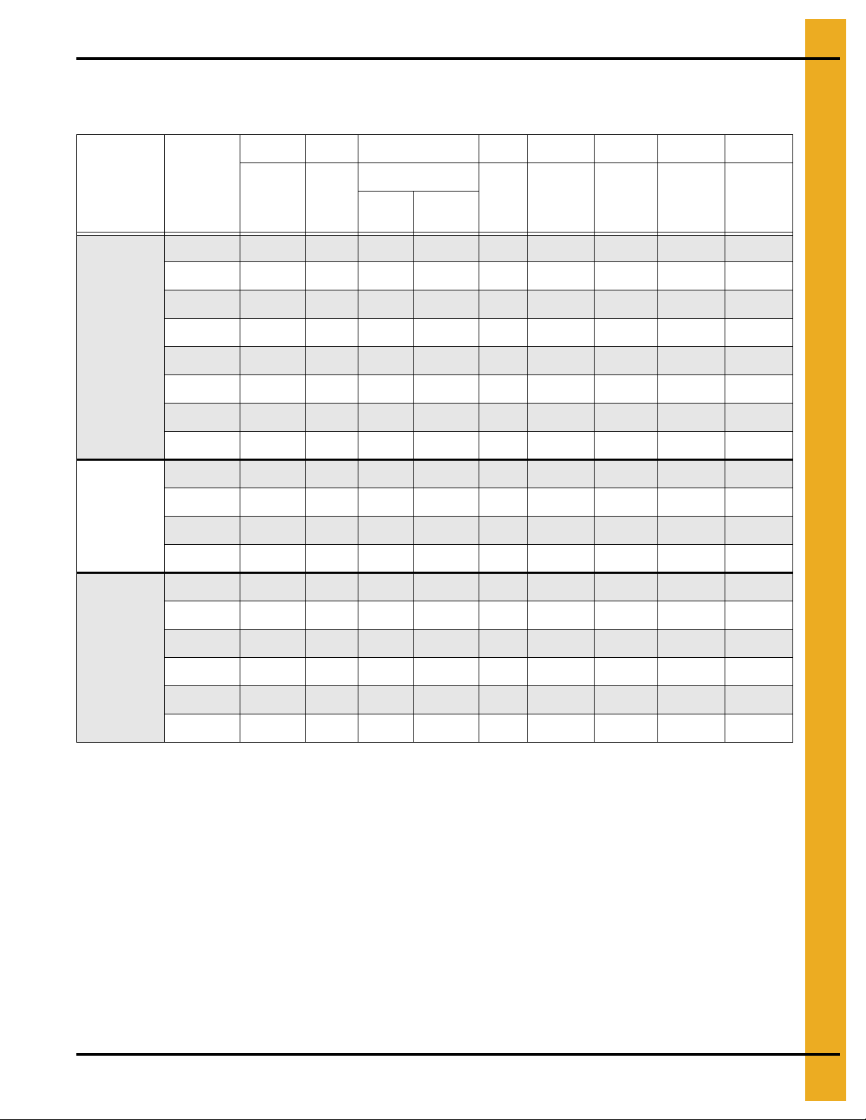
Page 35

All Stack Specifications
Total Holding Capacity (Bushels) 731 940 1044 1149 1304
Grain Column Holding Capacity (Bushels) 679 873 970 1067 1261
Fans
Top Auger 8" Dia. 5 HP 8" Dia. 5 HP 8" Dia. 7.5 HP 8" Dia. 7.5 HP 8" Dia. 10 HP
Capacity (BHP) 3800 3800 3800 3800 3800
Bottom Auger 8" Dia. 5 HP 8" Dia. 5 HP 8" Dia. 7.5 HP 8" Dia. 7.5 HP 8" Dia. 10 HP
Meter Roll Drive SCR, 1/3 HP SCR, 1/3 HP SCR, 1/3 HP SCR, 1/3 HP SCR, 1/3 HP
Capacity - Maximum Rate¹ (BHP) 1960 2520 2800 3080 3640
Electrical Load (Fans, Top and Bottom Augers²)
1 Phase, 220 Volt 226 - - - 3 Phase, 220 Volt 121 132 182 192 282
3 Phase, 440 Vo lt 61 66 91 96 141
3 Phase, 575 Volt 49 53 73 77 113
1
Actual discharge rate is cont rolled by meter roll speed adjustment, at 5% to 100% of maximum rate.
2
Excludes auxiliary load and unload conveyor equipment.
Total Holding Capacity (Bushels) 731 940 1044 1149 1304
Grain Column Holding Capacity (Bushels) 679 873 970 1067 1261
Fans
Top Auger 8" Dia. 5 HP 8" Dia. 5 HP 8" Dia. 7.5 HP 8" Dia. 7.5 HP 8" Dia. 10 HP
Capacity (BHP) 3800 3800 3800 3800 3800
Bottom Auger 8" Dia. 5 HP 8" Dia. 5 HP 8" Dia. 7.5 HP 8" Dia. 7.5 HP 8" Dia. 10 HP
Meter Roll Drive SCR, 1/3 HP SCR, 1/3 HP SCR, 1/3 HP SCR, 1/3 HP SCR, 1/3 HP
Capacity - Maximum Rate¹ (BHP) 1960 2520 2800 3080 3640
Electrical Load (Fans, Top and Bottom Augers²)
1 Phase, 220 Volt 244 244 - - 3 Phase, 220 Volt 138 138 196 196 308
3 Phase, 440 Vo lt 69 69 98 98 154
3 Phase, 575 Volt 55 55 78 78 123
1
Actual discharge rate is cont rolled by meter roll speed adjustment, at 5% to 100% of maximum rate.
2
Excludes auxiliary load and unload conveyor equipment.
5. Specifications
14' 18' 20' 22' 26'
28" 10-13 HP
40" 15 HP
14' 18' 20' 22' 26'
28" 10-13 HP
28" 10-13 HP
36" 10-12 HP
42" 20 HP
36" 10-13 HP
36" 10-13 HP
36" 15 HP
42" 25 HP
36" 15 HP
36" 15 HP
36" 15 HP
42" 30 HP
36" 15 HP
36" 15 HP
40" 25 HP
42" 40 HP
40" 25 HP
40" 25 HP
14' 18' 20' 22' 26'
Total Holding Capacity (Bushels) 1074 1381 1534 1688 1995
Grain Column Holding Capacity (Bushels) 1022 1314 1460 1606 1898
Fans
Top Auger 8" Dia. 5 HP 8" Dia. 5 HP 8" Dia. 7.5 HP 8" Dia. 7.5 HP 8" Dia. 10 HP
Capacity (BHP) 3800 3800 3800 3800 3800
Bottom Auger 8" Dia. 5 HP 8" Dia. 5 HP 8" Dia. 7.5 HP 8" Dia. 7.5 HP 8" Dia. 10 HP
Meter Roll Drive SCR, 1/3 HP SCR, 1/3 HP SCR, 1/3 HP SCR, 1/3 HP SCR, 1/3 HP
Capacity - Maximum Rate¹ (BHP) 1960 2520 2800 3080 3640
Electrical Load (Fans, Top and Bottom Augers²)
1 Phase, 220 Volt 286 - - - 3 Phase, 220 Volt 143 176 232 262 358
3 Phase, 440 Vo lt 72 88 116 131 179
3 Phase, 575 Volt 58 70 93 105 143
1
Actual discharge rate is cont rolled by meter roll speed adjustment, at 5% to 100% of maximum rate.
2
Excludes auxiliary load and unload conveyor equipment.
40" 15 HP
40" 15 HP
42" 20 HP
42" 20 HP
42" 25 HP
42" 25 HP
42" 30 HP
42" 30 HP
42" 40 HP
42" 40 HP
PNEG-1702 ETL Listed GSI/FFI Portable Dryer Manual 35
Page 36

5. Specifications
All Stack Specifications (Continued)
Total Holding Capacity (Bushels) 1074 1381 1534 1688 1995
Grain Column Holding Capacity (Bushels) 1022 1314 1460 1606 1898
14' 18' 20' 22' 26'
Fans
Top Auger 8" Dia. 5 HP 8" Dia. 5 HP 8" Dia. 7.5 HP 8" Dia. 7.5 HP 8" Dia. 10 HP
Capacity (BHP) 3800 3800 3800 3800 3800
Bottom Auger 8" Dia. 5 HP 8" Dia. 5 HP 8" Dia. 7.5 HP 8" Dia. 7.5 HP 8" Dia. 10 HP
Meter Roll Drive SCR, 1/3 HP SCR, 1/3 HP SCR, 1/3 HP SCR, 1/3 HP SCR, 1/3 HP
Capacity - Maximum Rate¹ (BHP) 1960 2520 2800 3080 3640
Electrical Load (Fans, Top and Bottom Augers²)
1 Phase, 220 Volt 304 - - - 3 Phase, 220 Volt 160 182 246 266 384
3 Phase, 440 Volt 80 91 123 133 192
3 Phase, 575 Volt 64 73 98 106 154
1
Actual discharge rate is control led by meter roll speed adjustment, at 5% to 100% of maximum rate.
2
Excludes auxiliary load and unload conveyor equipment.
Total Holding Capacity (Bushels) 1074 1381 1534 1688 1995
Grain Column Holding Capacity (Bushels) 1022 1314 1460 1606 1898
28" 10-13 HP
40" 15 HP
14' 18' 20' 22' 26'
36" 10-13 HP
42" 20 HP
36" 15 HP
42" 25 HP
36" 15 HP
42" 30 HP
40" 25 HP
42" 40 HP
Fans 28" 10-13 HP 36" 10-13 HP 36" 15 HP 36" 15 HP 40" 25 HP
Top Auger 8" Dia. 5 HP 8" Dia. 5 HP 8" Dia. 7.5 HP 8" Dia. 7.5 HP 8" Dia. 10 HP
Capacity (BHP) 3800 3800 3800 3800 3800
Bottom Auger 8" Dia. 5 HP 8" Dia. 5 HP 8" Dia. 7.5 HP 8" Dia. 7.5 HP 8" Dia. 10 HP
Meter Roll Drive SCR, 1/3 HP SCR, 1/3 HP SCR, 1/3 HP SCR, 1/3 HP SCR, 1/3 HP
Capacity - Maximum Rate¹ (BHP) 1960 2520 2800 3080 3640
Electrical Load (Fans, Top and Bottom Augers²)
1 Phase, 220 Volt 340 340 - - 3 Phase, 220 Volt 194 194 274 274 436
3 Phase, 440 Volt 97 97 137 137 218
3 Phase, 575 Volt 78 78 110 110 174
1
Actual discharge rate is control led by meter roll speed adjustment, at 5% to 100% of maximum rate.
2
Excludes auxiliary load and unload conveyor equipment.
36 PNEG-1702 ETL Listed GSI/FFI Portable Dryer Manual
Page 37

All Stack Specifications (Continued)
5. Specifications
Figure 5K
A BCD
14' 23'-1-1/2" 2'-2" 14'-0" 4'-8" 16" Min. 11'-2" 4'-9-3/4" 0'-8" 8'-0" 23'-9-1/2" 10'-0" 6'-4"
18' 27'-1-1/2" 2'-2" 18'-0" 4'-8" 16" Min. 11'-2" 4'-9-3/4" 0'-8" 8'-0" 23'-9-1/2" 10'-0" 6'-4"
20' 29'-1-1/2" 2'-2" 20'-0" 4'-8" 16" Min. 11'-2" 4'-9-3/4" 0'-8" 8'-0" 23'-9-1/2" 10'-0" 6'-4"
22' 31'-1-1/2" 2'-2" 22'-0" 4'-8" 16" Min. 11'-2" 4'-9-3/4" 0'-8" 8'-0" 23'-9-1/2" 10'-0" 6'-4"
26' 35'-1-1/2" 2'-2" 26'-0" 4'-8" 16" Min. 11'-2" 4'-9-3/4" 0'-8" 8'-0" 23'-9-1/2" 10'-0" 6'-4"
1
E
FGHJLMN
1. A 12" thick reinforced concrete foundation and 16" pedestal (min.) are required. See bulletin
FL-02-2 for details. 32" Thick pedestal required for heat reclaimer option (see bulletin FL-03-2
for details).
2. Approximate location of standard service platform shown. See bulletin SP-02-2 for details.
For information on optional catwalk, see bulletin CATH-01-5.
3. For safety cage information, refer to bulletin SC-01-2.
PNEG-1702 ETL Listed GSI/FFI Portable Dryer Manual 37
Page 38

5. Specifications
H
G
L
D
E
B
C
A
J
K
N
F
14'-0"
SEE
NOTE 2
2'-8"-REAR SAFETY CAGE
SEE NOTE 3
7'-9"-SAFETY
PLATFORM
13'-0"-OPTIONAL
CATWALK
SEE
NOTE 1
All Stack Specifications (Continued)
Figure 5L
A BCD
14' 23'-1-1/2" 2'-2" 14'-0" 4'-8" 16" Min. 11'-2" 4'-9-3/4" 0'-8" 8'-0" 3'-0" 23'-9-1/2" 6'-4"
18' 2 7' - 1-1/2" 2'-2" 18'-0" 4'-8" 16" Min. 11'-2" 4'-9-3/4" 0'-8" 8'-0" 3'-0" 23'-9-1/2" 6'-4"
20' 29'-1-1/2" 2'-2" 20'-0" 4'-8" 16" Min. 11'-2" 4'-9-3/4" 0'-8" 8'-0" 3'-0" 23'-9-1/2" 6'-4"
22' 3 1' - 1-1/2" 2'-2" 22'-0" 4'-8" 16" Min. 11'-2" 4'-9-3/4" 0'-8" 8'-0" 3'-0" 23'-9-1/2" 6'-4"
26' 35'-1-1/2" 2'-2" 26'-0" 4'-8" 16" Min. 11'-2" 4'-9-3/4" 0'-8" 8'-0" 3'-0" 23'-9-1/2" 6'-4"
E
1
FGHJKLN
1. A 12" thick reinforced concrete foundation and 16" pedestal (min.) are required. See bulletin
FL-02-2 for details. 32" Thick pedestal required for heat reclaimer option (see bulletin FL-03-2
for details).
2. Approximate location of standard service platform shown. See bulletin SP-02-2 for details.
For information on optional catwalk, see bulletin CATH-01-5.
3. For safety cage information, refer to bulletin SC-01-2.
38 PNEG-1702 ETL Listed GSI/FFI Portable Dryer Manual
Page 39

Stack Dryer Foundation Specifications
Stack Dryer Foundation
Basket Length 14 18 20 22 26
5. Specifications
Concrete Pad Size (12' x “X”)
Concrete (Cubic Yards) 20-3/4 24-1/4 26 27-1/2 31
#4 Rebar (Feet)
Anchors
1
10" Depth with 36" wide x 36" deep footings along ea c h si de.
2
#4 Reinforcing rods on 1"-0" centers. Both dire c t io ns in slab and bottom of footing.
3
Use 3/4" x 9-5/8" minimum anchors with epoxy. GSI part #: Anchor (GTC-0003) epoxy (GTC-0004).
3
²
¹
Minimum soil bearing capacity = 2000 PSF.
Concrete specifications:
• Compressive strength at 28 days - 4000 PSI.
• Minimum cement content - 6 sacks/yard.
• Maximum slump - 4" ± 1".
12 x 24 12 x 28 12 x 30 12 x 32 12 x 36
900 1060 1140 1220 1400
16 20 22 24 28
PNEG-1702 ETL Listed GSI/FFI Portable Dryer Manual 39
Page 40

6. Competitor/Dri-Tek Test Firing
CAUTION
Before attempting to operate the dryer make sure all safety shields are in place, all
bottom clean-out and rear access doors are closed and all personnel are clear of
the dryer.
Before the dryer is filled, thoroughly inspect the unit and check the operation of the dryer as follows.
Inspect the Metering Rolls
Figure 6A 4" Meter Roll
Figure 6B 7" Meter Roll
Open all metering roll access doors and inspect each compartment for any bolts, nuts or other foreign
material, that may cause possible jamming of the metering rolls.
40 PNEG-1702 ETL Listed GSI/FFI Portable Dryer Manual
Page 41

Set Control Switches
Moisture Control Switch OFF
Moisture Control Thermostat 200°
Load Switch OFF
Unload Switch OFF
Fan Switch OFF
Burner Switch OFF
Out of Grain Timer 1 MINUTE (Reset to 8 Minutes after testing)
Load Delay 30 SECONDS
Unload Delay 30 SECONDS
Metering Roll Speed LOW AND HIGH SPEED SETTINGS PUT ON ZERO
Dry Timer 60 MINUTES
Cool Timer 20 MINUTES
6. Competitor/Dri-Tek Test Firing
Unload Timer 10 MINUTES
Mode Switch CONTINUOUS FLOW
Electrical Power
Turn ON the electrical power supply to the dryer. Set all circuit breakers to ON, including the safety
disconnect handle mounted on front of the dryer’s power panel.
Control Power Switch
Turn the Control Power switch to ON. The switch light comes on. “GSI” and the software version will
appear. At this point, the controller will lock out all other dryer functions and the dryer will perform its safety
circuit check. If a fault is found, the cause will be displayed on the LCD. If all safeties are safe, the controller
will supply power to the electronic fuel shut off valve (if so equipped). Press the Start button to initialize
the computer.
Power Start Button
Push the Start button and all the toggle switches on the control panel will be activated. This initializes the
load, fan, burner, unload and metering rolls individually.
Fuel Check
If using LP gas, make sure the tank has plenty of fuel an d that the
REGULATOR MOUNTED TO IT
If using LP gas, slowly open the main fuel supply valve at the tank. If using natural gas, turn ON the
valve along the supply line. Then, open the manual shut off valve on the dryer to allow fuel flow to the
dryer. Inspect all gas lines and connections for possible leaks. ANY GAS LEAKS NEED TO BE
FIXED IMMEDIATELY.
PNEG-1702 ETL Listed GSI/FFI Portable Dryer Manual 41
. If using natural gas, make sure an a dequate supply is available.
TANK DOES NOT HAVE A PRESSURE
Page 42

6. Competitor/Dri-Tek Test Firing
Load Auger
With the grain supply shut off, quickly bump the Load Auger switch to MANUAL and see if the load auger
rotates clockwise, as viewed from the drive end, or counterclockwise if the dryer is a front load model.
If the wet grain supply auxiliary is wired to the dryer it should also rotate in the correct direction at this time.
Turn the Load Auger switch to the AUTO position. The top auger and wet grain supply auxiliary should
run for one minute and then the dryer will shutdown leaving the safety shutdown message (out of grain)
displayed. Press the Dryer Power Stop button to reset the panel, then press the Start button to
resume operation.
1 Speed Operation
To check 1 Speed operation, place the Unload switch in the 1 Speed setting. Turn the high speed metering
roll dial up until the metering rolls start rotating. The bottom auger should rotate counterclockwise, as
viewed from the drive end. The metering roll drive motor should rotate clockwise, as viewed from the drive
end of the gearbox. If the dry grain take away auxiliary is wired to the dryer, it should start and rotate in
the proper direction.
Metering Roll Operation
To check the metering roll operation, turn high speed knob clockwise. The metering roll speed should
increase. Turning the knob counterclockwise will decrease the speed. Turn ON the Moisture Control switch.
If the grain temperature setpoint is set above the outside temperature, the system will switch to Low Speed
if working correctly. Make sure the drive chain tension is properly adjusted and all sections of the metering
rolls rotate. Turn the Unload switch OFF after these checks are complete. The bottom auger will continue
to run for 30 seconds after the switch is turned OFF to allow for clean out.
Figure 6C The Metering Roll Access Area
42 PNEG-1702 ETL Listed GSI/FFI Portable Dryer Manual
Page 43

6. Competitor/Dri-Tek Test Firing
WARNING
Dip switch number eight (#8) must be turned back to the OFF position after this
test is complete or no air testing will occur.
Fan Switch
Bump the Fan switch and observe the fan rotation. The fan should run counterclockwise. Sometimes on
3 phase models all motors on the dryer will run backwards. They can easily be reversed by interchanging
two of three power supply wires. Reverse the two (2) outside wires, L1 and L3 and leave the middle one
in the same position.
NOTE: If the dryer is empty, the burner does not operate. The fans cannot create enough static pressure
to engage the Air switch. You will receive a “no airflow” message. To start the dryer when it is low
on grain, the Airflow switches must be turned OFF. Switching Dip Switch number eight (#8), on the
back of the computer control board, to ON turns the Air Switch OFF.
Burner Safety
To check the burner safety function, make sure the main gas valve is OFF. Turn the Fan switch ON and
allow the fan to start. Then, turn the Heater switch ON. The dryer will shutdown after 20 seconds. The
safety message, “loss of flame” will appear.
Burner Test Fire
The following test should be done with grain in the d ryer. If no g rain is pre sent, set approximate pr essure
settings and fine tune when grain arrives. Test fire the burner by starting the fan and then turn the
Burner switch to ON with the fuel supply turned ON. The heater should ignite after a short purge delay of
approximately 10 seconds. Gas pressure should be shown on the gauge. At this time, set the high-fire and
low-fire pressure settings. Use the pressure regulator (See Figure 6D on Page 44) for high-fire and the
needle valve located in the side of the cycle solenoid (low-fire) valve (See Figure 6D on Page 44) for
low-fire. The burner should cycle between high-fire and low-fire, approximately 2 or 3 times per minute.
Approximate settings s hould be:
LP Gas Natural Gas
High-Fire 6-15 lbs. High-Fire 6-10 lbs.
Low-Fire 2-6 lbs. Low-Fire 1-3 lbs.
If the burner remains on high-fire and does not cycle, increase t he regula tor setting, in o rder to rea ch the
thermostat setting. If the burner remains in low-fire and does not cycle, slightly decrease gas pressure with
the low-fire solenoid needle valve. If the gas pressure is decreased too much, a popping or fluttering
sound will be heard. Be sure to adjust the low pressure needle valve anytime the high pressure regulator
is adjusted.
PNEG-1702 ETL Listed GSI/FFI Portable Dryer Manual 43
Page 44

6. Competitor/Dri-Tek Test Firing
Low-fire
needle valve
Pressure regulator
(high-fire)
Watch gauge
for pressure
Relief valve
Low-fire
needle valve
Supply line ball
valve (high-fire)
Regulator
Relief valve
Watch gauge
for pressure
Figure 6D Liquid Propane (LP) Pipe Train
Figure 6E Natural Gas (NG) Pipe Train
44 PNEG-1702 ETL Listed GSI/FFI Portable Dryer Manual
Page 45

6. Competitor/Dri-Tek Test Firing
WARNING
Dip switch number eight (#8) must be turned back to the OFF position after this
test is complete or no air testing will occur.
Staged Batch Check
The following test must be done with grain in the dryer or with the Air switch turned OFF as noted in the
Fan switch section on Page 43. To check the staged batch operation, turn the Control Power switch to the
ON position. Open the main fuel supply valve at the tank on an LP dryer or open the valve in the fuel supply
line on a natural gas dryer. Turn the Drying Mode switch to the staged b atch position. Turn ON the electric
shut off valve to allow fuel flow to the dryer. Turn the Load switch to AUTO, the Unload switch to 1 Speed
and the fan and burner to ON. Push the Dryer Power Start button and the controller will sequentially start
all dryer components in their proper order. If any switches are not in their correct position for staged batch
operation, the dryer will indicate improper switch position and will not start until the switches are in the
proper position. After starting, all batch timers will time down in sequence. When the unload cycle is
complete, the timers will automatically reset to their original settings and start the dryer timer again.
NOTE: If the dryer is empty, the burner does not operate. The fans cannot create enough static pressure
to engage the Air switch. You will receive a “no airflow” message. To start the dryer when it is low
on grain, the Airflow switches must be turned OFF. Switching Dip Switch number eight (#8), on the
back of the computer control board, to ON turns the Air Switch OFF.
Stopping Dryer Operation
To stop operation of the dryer, push the Dryer Power Stop button. The fan, burner and all augers will
stop immediately.
Dryer Shutdown
To shutdown the dryer, first close the fuel supply valve at the tank or valve along the fuel line. If the burner
is operating, let the dryer run out of fuel and it will shutdown automa tically due to lo ss of flame. Close the
fuel valve at the dryer and press the Dryer Power Stop button. Turn OFF the safety disconnect handle on
the front of the power box and turn OFF the main power to the dryer.
Emergency
In case of emergency, push the Emergency Stop button located at the bottom of the upper control box.
(See Page 9.)
PNEG-1702 ETL Listed GSI/FFI Portable Dryer Manual 45
Page 46

7. Vision Test Firing
Before attempting to operate the dryer , make sure all safety shields are in pl ace, all
bottoms are cleaned out and rear access doors are closed and all personnel are
clear of the dryer.
WARNING
Any gas leaks must be fixed immediately.
Dryer Pre-Season Checks
Before staring the drying for the first time in a drying season, perform the following checks. If any of the
checks fail to produce the stated result, the customer should consult the dealer.
Do not attempt to use the dryer unless all the pre-start checks have been successfully completed.
WARNING
Inspect the Metering Rolls
Open all metering roll access doors and inspect each compartment for any bolts, nuts or other foreign
material that may cause possible jamming of the metering rolls.
Check Control Panel Switches
Before applying electrical power to the dryer, be sure that all switches on the dryer control panel are in the
OFF position.
Electrical Power
Turn ON the electrical power supply to the dryer, set all circuit breakers to ON, including the safety
disconnect handle mounted on front of the dryer power panel.
Control Power Switch
Turn the Control Power switch to ON. At this point, the controller will lock ou t all other dryer functions. Once
the Boot Screen appears, touch the Start button and the dryer will perform a safety circuit check. If a f ault
is found, the cause will be displayed on the main screen. If all are safe, the controller will sup ply power to
the electronic fuel shut off valve (maxon), if so equipped and the Start switch will illuminate, indicating that
the dryer is ready to be started.
Start Switch
Push the Start switch and all the selector switches on the control panel will be activated.
Fuel Check
If using LP gas, make sure the tank has plenty of fuel and that the tank does not have a regulator mounted
on the liquid line. Slowly open the main fuel supply valve at th e tank. Then, open the manual shut off valve
on the dryer to allow fuel flow to the dryer.
If using natural gas, make sure an adequate supply is available. Turn ON the valve along the supply
line. Then, open the manual shut off valve. Inspect all gas lines and connections for possible leaks.
46 PNEG-1702 ETL Listed GSI/FFI Portable Dryer Manual
Page 47

7. Vision Test Firing
Load Auger
With the grain supply shut off, quickly flip the Load Auger switch to MANUAL and see if the load auger
rotates clockwise as viewed from the drive end, or counterclockwise if the dryer is a front load model. If
the wet grain supply auxiliary is wired to the dryer, it should also rotate in the correct direction at this time.
Turn the Load Auger switch to the AUTO position. The top auger and wet grain supply auxiliary should run
for 8 minutes. The dryer will then shutdown and the safety shutdown message: Out of grain will display.
Press the Stop button to reset the panel, then press the Start button.
Unload Auto Operation
To check Auto operation, place the Unload switch in the AUTO position. Push then turn the meter roll dial
to a setting of 500 and touch ACCEPT/EXIT to start the meter roll rotation. The bottom auger should rotate
counterclockwise as viewed from the drive end. The meter roll drive motor should rotate clockwise as
viewed from the drive end of the gearbox. If the dry grain take away auxilia ry is wired to the dryer, it should
start and rotate in the proper direction.
Unload Manual Operation
To check Manual operation, move the Unload switch in the MANUAL position. Push then turn the meter
roll dial to a setting of 500 and touch ACCEPT/EXIT to start the meter roll rotation. The bottom auger
should rotate counterclockwise as viewed from the drive end. The meter roll drive motor should rotate
clockwise as viewed from the drive end of the gearbox. If the dry grain take away auxiliary is wired to the
dryer, it should start and rotate in the proper direction.
Meter Roll Operation
Meter Roll Operation 4" (GSI)
When the meter rolls are set to maximum (1000), the meter roll speed should be 17.5 RPM for 8'' (20 cm)
discharge augers. Make sure the drive chain tension is properly adjusted and all sections of the meter rolls
rotate. Turn the Unload switch OFF after these checks are complete. The bottom auger will continue to
run for 60 seconds (the default clean out delay setting) after the switch is turned OFF to allow for clean out.
Meter Roll Operation 7" (FFI)
To check the meter roll operation turn the knob clockwise and the meter roll speed should increase.
Turning the knob counterclockwise will decrease the speed. When the meter rolls are set to maximum
(1000), the meter roll speed should be 4.3 RPM for 8" (20 cm) discharge augers. Make sure the drive chain
tension is properly adjusted and all sections of the meter rolls rotate. Turn the Unload switch OFF after
these checks are complete. The bottom auger will continue to run for 60 second s (default clean out delay
setting) after the switch is turned OFF to allow for clean out.
NOTE: Due to the nature of the DC drive motor used on the meter rolls, it is possible for the brushes inside
the motor to become corroded if the dryer has not been operated for several months. This will
cause the meter rolls not to function. To fix this problem, use a rubber mallet or a piece of wood t o
tap the DC drive motor. The shock is usually sufficient to re-start the motor and metering rolls. You
should not have any more problems with this during the rest of the drying season.
PNEG-1702 ETL Listed GSI/FFI Portable Dryer Manual 47
Page 48

7. Vision Test Firing
All power should be switched OFF and locked out before attempting to reverse
the connections.
Fan Switches
Briefly turn each Fan switch to ON and observe the fan rotation. The fan should run counterclockwise.
Sometimes on 3 phase models, all motors run backwards. They can easily be reversed by interchanging
two of the three power supply wires. Reverse the two (2) outside wires, L1 and L3 and leave the middle
one in the same position.
WARNING
NOTE: The bottom fan on the dryer is always referred to as fan 1.
Burner Safety
To check the burner safety function, first make sure the main gas valve is OFF. Turn the Fan switch ON
and allow the fan to start. Turn the Heater switch ON for that fan. The dryer will shutdown after
20 seconds. The safety message, “Ignition Failure Fan #” will appear. Reset the dryer and repeat for the
other fan/heater(s).
Burner Test Fire
To perform this test, the dryer must be full of grain, otherwise the air switch will need to be disabled,
if the dryer is empty. To disable, touch the Setup button at the bottom of the Default Operation Screen.
When the Setup Screen appears touch the Diagnostics button to display the system diagnostics. To
disable the air switch select the Disable Testing button in the air switch box of the System Diagnostics
Screen. The vision computer will then display a prompt asking if you wish to disable the air switch. Choose
yes to continue. Once the air switches are disable the Fan switches on the switch panel will illuminate and
the fan/heaters on the display animation will change to blue indicating that “airflow” is simulated.
There is only a 5 minutes period after the dryer is turned ON that the air switches can be disabled. After
that time the Air switches cannot be disabled and any Air switches that are disabled will return to the
enabled state causing an airflow shutdown if the d ryer is empty. To restart the 5 minutes testing period the
dryer must be shutdown and restarted. The 5 minutes testing period starts when the Control Power switch
is turned ON.
Test fire each burner by starting the fan. Turn on the fuel supply then, turn the Burner switch to ON and
the burner should ignite after a short purge delay of approximately 10 seconds. Gas pressure should be
shown on the gauge. At this time adjust the plenum setpoint to 200°F (93°C), causing the burner to operate
on high-fire. Observe the gas pressure on the gauge and lower the plenum setpoint until it causes the
burner to cycle into low-fire. When the plenum temperature setpoint is met, the gas pressure should show
a noticeable drop, indicating that the cycle solenoid is closed and the burner is being supplied with less
gas through the cycle solenoid bypass port. At this time set the high-fire and low-fire pressure settings.
Use the pressure regulator for high-fire and the adjustment screw on the cycle solenoid for low-fire. The
computer should cycle the burners between high and low, approximately 1 to 3 times per minute.
Use only the amount of pressure required to obtain the desired temperature.
48 PNEG-1702 ETL Listed GSI/FFI Portable Dryer Manual
Page 49

7. Vision Test Firing
Low-fire
needle valve
Pressure regulator
(high-fire)
Watch gauge
for pressure
Relief valve
Approximate setting should be:
LP Gas Natural Gas
High-Fire 6-15 PSI (41-102 kPa) High-Fire 6-10 PSI (41-69 kPa)
Low-Fire 2-6 PSI (14-41 kPa) Low-Fire 1-3 PSI (7-20 kPa)
If the burner remains on high-fire and does not cycle, increase t he regula tor setting, in o rder to rea ch the
plenum setpoint. If the burner remains in low-fire and does not cycle, slightly decrease gas pressure with
the low-fire adjustment screw on the cycle solenoid. If the gas pressure is decreased too much, a popping
or fluttering sound will be heard. This popping and fluttering should not be allowed to continue, or damage
to the burner will occur. Be sure to adjust the low pressure needle valve anytime the high pressure
regulator is adjusted. Repeat the test for each fan/heater unit.
PNEG-1702 ETL Listed GSI/FFI Portable Dryer Manual 49
Figure 7A Liquid Propane (LP) Pipe Train
Page 50

7. Vision Test Firing
Watch gauge
for pressure
Low-fire
needle valve
Supply line ball
valve (high-fire)
Regulator
Relief valve
Figure 7B Natural Gas (NG) Pipe Train
Dryer Shutdown
To shutdown the dryer:
1. Close the fuel supply valve at the tank or valve along the fuel line.
2. If the burner is operating, let the dryer run out of fuel and it will shutdown automatically due to loss
of flame.
3. Close the fuel valve at the dryer and press the Stop button.
4. Turn OFF the control power.
5. Turn OFF the safety disconnect handle on the front of the power box and turn OFF the main power
to the dryer.
Emergency
In case of emergency, push the Emergency Stop button. This will interrupt powe r to the control panel and
the fan; burner and all augers will stop immediately.
50 PNEG-1702 ETL Listed GSI/FFI Portable Dryer Manual
Page 51

8. Competitor Dryer Operation
Always disconnect and lock out power before working on or around dryer.
Continuous Flow Operation
Standard electrical safety practices and codes should be used when working with a dryer. Refer to the
National Electric Code standard handbook by the National Fire Protection Association. A qualified
electrician should make all wiring installations.
WARNING
Full Start-Up Check
This start-up procedure assumes the following:
1. You have read and understand the DRYER OPERATION AND SERVICE MANUAL.
2. You have taken special note of all SAFETY PRECAUTIONS.
3. All safety shields are in place.
4. All meter roll access doors have been opened and all foreign objects have been removed.
5. A pre start-up check has been performed.
6. All motors have been checked for proper rotation.
7. All heaters have been test fired.
8. The fuel has been turned ON at the tank.
9. The electric power has been turned ON.
10. The main disconnect switch on the dryer is ON.
11. There is wet grain in the wet holding bin.
12. The incoming grain moisture is known.
13. Dry grain take away equipment is in place.
14. Grain is going to the proper bin.
15. All switches have been set to the OFF position.
16. The Load Tilt switch box is installed with the side stamped up, in the UP position.
Filling the Dryer
1. Turn the Control Power switch to ON.
2. Turn the Drying Mode switch to CONTINUOUS FLOW.
3. Make sure the Fan, Burner and Unload switches are in the OFF position.
4. Push the Dryer Power Start switch.
5. Turn the Load Auger switch to the MANUAL position to fill the dryer. The load auger should start and
run until the dryer is full, then shut off automatically. (If the switch is set to the AUTO position, the dryer
will shutdown each time the out of grain timer times out and will have to be restarted.)
6. When the dryer has filled, turn the Load Auger switch to the AUTO position.
PNEG-1702 ETL Listed GSI/FFI Portable Dryer Manual 51
Page 52

8. Competitor Dryer Operation
Staged Batch Operation
1. Turn the Control Power switch to ON.
2. With load, unload, fan and burner turned OFF, turn the Drying Mode switch to continuous then push
the Dryer Power Start switch to arm the safety circuit. Turn the Load switch to ON and fill the dryer
with grain. The load auger will stop when full if the Load Tilt Switch is installed and set properly.
3. Turn the Drying Mode switch to staged batch.
4. Open the main fuel supply valve on the tank if using LP gas, or the valve in the fuel supply line if using
natural gas. Open the manual shut off valve to allow fuel flow to the dryer.
5. Set switches to the following settings:
Load AUTO (For timed shutdown when out of grain. ON will shut off auger when full,
but will not shut dryer down when out of grain.)
Fan AUTO (To stop during unloading. ON to continue cooling during unloading.)
Heater AUTO (For dry and cool. ON for all heat.)
Unload 1 Speed
Fan/Heater Switch Settings
Fan Setting Heater Setting Fan Function Heater Function
AUTO AUTO Fans stay ON during dry and cool cycle only
AUTO ON Fans stay ON during dry and cool cycle only Burners stay ON during dry and cool
ON ON Fans are ON continuously Burners are ON continuously
ON AUTO Fans are ON continuously
At the end of the dry cycle in staged batch, the fans and heaters will continue running if the MOISTURE CONTROL is “ON”,
until the preset temperature on the moisture control thermostat is reached.
Burners stay ON during dry timer
cycle only
Burners shutdown at the end of the
dry cycle
6. Make sure the Load Auger switch is set to AUTO. In both the AUTO and MANUAL position, the
Grain Level switch will automatically keep the dryer full of grain. In the AUTO position, the dryer will
shutdown after the preset time period on the out of grain timer, or if the grain flow to the dryer
is interrupted.
7. To properly set the correct dry, cool and unload time for various moisture content grains, refer chart
to PNEG-1650/PNEG-1651.
8. To start the drying operation, push the Dryer Power Start button. The controller will start all the dryer
components in their proper order. If any of the selected switches are improperly positioned for staged
batch drying, the display will indicate the proper switch position and will not allow the dryer to operate
until the position of the switch is corrected.
9. The fan will start and airflow is checked.
10. After purging for approximately 10 seconds the heater will fire. For information concerning heater
adjustment, see the dryer pre- start checks on Page 40.
52 PNEG-1702 ETL Listed GSI/FFI Portable Dryer Manual
Page 53

8. Competitor Dryer Operation
11. If the dryer is being operated in all heat, move the Fan switch to the ON position. In this position, the
fan will run continuously during the dry, cool and unload stages of the staged batch operation. If the
dryer is being operated in the dry and cool mode, the preferred position for the Fan switch is the ON
position, so the fan will run continuously and continue to cool the grain during the unload operation.
If desired, the fan can be turned OFF during the unload cycle of the dry-cool-unload sequence by
turning the Fan switch to AUTO.
12. If the dryer is being operated in all heat, move the Heater switch to ON. The burner will operate
whenever the fan is operating. If the dryer is being used in dry and cool, turn the Heater switch to
AUTO and the burner will automatically shutdown during the cooling and unloading cycles.
13. The bottom auger and metering rolls will start automatically during the unload cycle of the
dry-cool-unload mode, along with any grain handling equipment that is wired to the dryer. Th e speed
at which the metering rolls operate during the unload cycle is adjusted by using the high speed
metering roll knob. Turning the dial clockwise will increase the grain discharge rate and turning it
counterclockwise will decrease the discharge rate.
14. When the last batch is done and the dryer is out of grain, turn the Drying Mode switch to contin uous.
Turn the Load, Unload, Fan/Heater switches OFF and push the Dryer Power Start switch to arm t he
safety circuit. Run the fan/heater manually for 6 minutes per point of moisture to be removed.
Turn the burner OFF to cool the grain for 30 minutes. Turn OFF the fan and manually unload the
dryer by turning the Unload switch to 1 Speed and setting the meter rolls as fast as the unload
equipment will allow.
15. To control the length of the dry cycle using only the dry time setting programmed into the system,
turn the MOISTURE CONTROL setting to OFF. To use the automatic moisture control so that the
dry time is determined, not only by the dry time setting, but also by the moisture content of the drying
grain, turn the Moisture Control switch to ON.
16. To shutdown the dryer, close the fuel supply valve at the fuel tank or fuel source. If the burner is
operating, let the dryer run out of fuel, causing an automatic shutdown due to a loss of flame . Close
the fuel valve at the dryer and press the Dryer Power Stop button. Turn OFF the dr yer’s main circuit
breaker located on the front of the power panel. Turn OFF the main power supply to the dryer.
17. In case of an emergency, press the Dryer Power Stop button. The burner, fan and all augers will
stop immediately.
Starting the Dryer
This start-up procedure is for a cold start on wet grain for continuous flow operation.
1. Turn ON the LP gas tank and any other manual gas valve at this time. Set the MAXON or FAST
ACTION HAND VALVE, if so equipped, on the incoming fuel line to the ON position.
2. Make sure the Moisture Control switch is in the OFF position.
3. Turn the Fan switch to the ON position.
4. Adjust the Air Pressure switch if necessary.
5. Turn the Heater switch to the ON position. The heater will purge for about 10 seconds then ignite. If
flame is detected the dryer will run, if not, a “loss of flame” error will occur. If this happens, check ga s
supply and all valves in the fuel line to make sure they are ON and attempt again.
PNEG-1702 ETL Listed GSI/FFI Portable Dryer Manual 53
Page 54

8. Competitor Dryer Operation
Adjusting the Temperature
1. Press the Program (Temperatures) button until the “carrot” is above the timer to be modified.
2. Use the UP and DOWN arrow keys to change the present temperature to the desired setting. The
new temperature is automatically accepted.
3. Keep pressing the Program (Temperatures) button until the carrot disappears or press the Mode
Select button once to exit.
4. On LP and NG gas models, adjust the PRESSURE REGULATOR (high-fire) on the burner fuel
line, so that burner will reach the thermostat setting and switch to low-fire.
The approximate settings should be:
LP Gas Natural Gas
High-Fire 6-15 lbs. High-Fire 6-10 lbs.
Low-Fire 2-6 lbs. Low-Fire 1-3 lbs.
Do not set the low-fire pressure so low that a popping or fluttering sound is heard in the heater. If
popping or fluttering sound are heard, increase the pressure until the sound goes away.
On LP and NG gas models adjust the needle valve on the cycle solenoid (low-fire valve) so that the
burner maintains flame then switches back to high-fire.
5. Adjust the burner pressure so that the burner CYCLES 2 to 3 times per minute (approximately 15 to 20
seconds on HIGH and approximately 5-8 seconds on LOW). Increasing the gas pressure with the gas
regulator increases the cycling rate and lowering it decreases the rate. This is the primary way to
change the cycling rate.
Decreasing the low pressure setting with the needle valve will also increase the rate while increasing
that pressure will decrease the rate.
6. On LP gas models adjust the vaporizer so the fuel pipes going to the burner from the regulator are
warm to the touch (not hot and cold).
The vaporizer can be adjusted two (2) ways. First, by loosening the bolt in the hinging mechanism and
swinging it to a hotter or cooler position. Second, by loosening the two (2) bolts in the hinge pipe and
sliding the vaporizer in or out to a cooler or hotter position. Either one or both methods may need to be
used to get the vaporizer to the proper temperatu re, but the first almost always gives adequate adjustment.
Natural gas does not use a vaporizer.
54 PNEG-1702 ETL Listed GSI/FFI Portable Dryer Manual
Page 55

8. Competitor Dryer Operation
Full Heat Continuous Flow Operation
1. Refer to PNEG-1650/PNEG-1651 DRYER START-UP. (CONTINUOUS FLOW METER ROLL
SETTINGS - FULL HEAT.) There are settings for initial moisture, moisture removed, approximate dry
time, 1 Speed, 2 Speed low and 2 Speed high. Select the line that indicates the initial moisture.
These are the settings referred to throughout this start-up procedure.
2. Make sure the Unload switch is OFF.
3. Make sure the Moisture Control switch is OFF.
4. If the dryer is stopped, press the Start switch to lock in the control circuit.
5. Turn the Fan and Burner switches to the “ON” position to run fans and burners. Be sure to adjust
the plenum temperature to 180°F for all burners. Run the fans and burners for about 10% longer
than the approximate dry time (refer to PNEG-1650/PNEG-1651) for the incoming moisture.
Example: Ten points removal from the chart is 54 minutes, plus 5.4 minutes (10%) equals
59.4 minutes (round up to 60).
6. Increase the drying temperature to a maximum of 210°F (corn) for single fan dryers. For multiple fan
dryers adjust the top burner to a maximum of 230°F (corn) and stage the temperature of the lower
burners down 30° per burner. Example: 3 fan dryer Top burner: 23 0°, Middle burner: 200°, Bottom
burner: 170°.
7. After the initial fan and burner run time, set the Unload switch to “1 Speed” and set the high speed
meter roll potentiometer to the setting for 1 Speed (refer to PNEG-1650/PNEG-1651). Meter rolls
should start and grain will begin to flow from discharge of dryer. Run time for this step should be
the same as from Step 5 above. DO NOT TO ADJUST THE DRYER DURING THIS PERIOD.
The grain discharging towards the end of this period will be over dried, but it is necessary so that the
corn moisture is staged properly and evenly in the dryer.
8. Turn the Moisture Control switch to “ON”. Set the moisture control (grain) temperature to 100°F.
9. Turn the Unload switch to “2 Speed”. Find the “2 Speed High” and “2 Speed Low” meter roll settings
(refer to PNEG-1650/PNEG-1651) and set meter roll potentiometers accordingly. Allow the dryer to
run for the time established in Step 5 and then sample the grain. If the dryer has been cycling
regularly from high to low and the grain is not coming out to moisture desired, then adjust the
moisture control (grain) temperature up or down 5° per point of moisture. Example: Moisture control
is set to 100°, desired moisture is 15%, sampled moisture is 17%. Adjust moisture control to 110°.
EVERY TIME AN ADJUSTMENT IS MADE IT IS IMPERATIVE THAT THE DRYER IS ALLOWED
TO RUN FOR THE ESTABLISHED TIME IN ORDER FOR CHANGES TO TAKE AFFECT. Repeat
this process as necessary until desired moisture content is being discharged from dryer.
10. After the run time in Step 9, the moisture control and the meter roll spee ds can be adjusted if required.
Each time an adjustment to the moisture control is made, it will take approximately the time as shown
in the example in Step 5 to see the results of this adjustment.
PNEG-1702 ETL Listed GSI/FFI Portable Dryer Manual 55
Page 56

8. Competitor Dryer Operation
Adjusting the Moisture Control
1. 5° on the moisture control will change the output moisture by about 1%. Example: With 100° set, the
result is 16% corn but 17% corn is desired. Reduce the moisture control setpoint temperature by 5°
to 95°. This should change the moisture out to about 17%. If you want the corn to come out dryer,
raise the temperature on the moisture control setpoint.
2. Four (4) sensors are averaged together for sensing moisture control temperature, one on each side
of the dryer in the front and one on each side of the dryer in the back. They are locat ed about 1/3 of
the way up the grain column from the bottom and in from the side about 4''.
3. Grain temperatures can be monitored by pressing the Mode Select button.
4. The moisture control should stay on HIGH about 50% to 90% of the time. There is a broad range that
will work. It should switch from low to high and back again to main tain the desired moisture. A control
that does not switch will not maintain an evenly dried grain moisture when the incoming wet grain
moisture varies.
5. If the Metering Roll switches to LOW and stays there for long periods of time, both the high a nd low
speed potentiometers should be slowed down 2% (20 points) and monitored for further adjustment.
6. If the Metering Roll switches to HIGH and stays on HIGH more then 90% of the time, increase the
speed on both potentiometers 2% (20 points) and monitor for further adjustment.
7. When adjusting the METER ROLL SPEEDS it is better not to change the speed more than 20 points
(2%) at a time.
8. Anytime a change is made, wait the approximate dry time for t hat moisture grain from the chart (refer
to PNEG-1650/PNEG-1651) before checking the grain moisture level and making another change
if necessary.
56 PNEG-1702 ETL Listed GSI/FFI Portable Dryer Manual
Page 57

9. Vision/Dri-Tek Dryer Operation
Dryer Start-Up and Operation Full Heat Drying
Full Heat Operation
With this type of drying, the grain is discharged hot, with no cooling. Drying capacity is substantially higher
with full heat than the dry and cool process.
Final Moisture
The cooling process usually removes 1% to 3% moisture, so hot shelled corn is removed from the dryer
at about 17% moisture if the final desired moisture content is 15%.
Drying Temperatures
Shelled Corn
For shelled corn with an initial moisture content of 25%-30%, the recommended maximum drying
temperature is 220°F-240°F (104°C-116°C) for the top fan and 170°F-190°F (77°C-88°C) for the
bottom fan.
Small Grain
For drying small grain (wheat, oats, milo), 150°F (66°C) is suggested.
Soybeans
Drying temperatures are critical in drying rice and soybeans. A temperature of 130°F (54°C) is
recommended to keep grain temperature low.
Drying Efficiency
The general rule for obtaining the highest drying efficiency is to use the highest possible drying
temperatures that does not adversely affect grain quality.
Dryer Shutdown
Cooling Hot Grain
If the dryer is to be shutdown while filled with grain, it is recommended that hot grain be cooled for
10 to 15 minutes, especially in cold weather, to prevent water vapor condensation and possible freezing
of such condensate following shutdown.
Initial Setup Parameters
Turn the Control Power switch to ON. When the Boot Screen appears, select the Start button. The
computer will run a quick check of the system network, after which the Default Operation Screen
will appear.
Timer and Delay Settings
To set the timers, select the button at the bottom of the Default Operation Screen. The “Select
Timers to Modify” Screen will appear. See instructions in Vision Manual to set the timer and delays.
PNEG-1702 ETL Listed GSI/FFI Portable Dryer Manual 57
Page 58

9. Vision/Dri-Tek Dryer Operation
Setting the Temperatures
To adjust the temperature setpoints, touch the button at the bottom of Default Operation Screen.
The “Select Temperature Setpoint to Modify” Screen will be displayed. See Vision Manual fo r instructions
on how to set the temperatures.
Start-Up
Start-Up Procedure
At the beginning of each harvest and before filling the dryer with grain, make sure to inspect the dryer for
rodent damage, proper belt and chain tension and missing or damaged safety shields. Test operate the
dryer using the pre-start check procedures on Page 46.
1. Before attempting to operate the dryer, make sure that all safety shields are in place, all plenum
bottom closure panel doors are closed, all rear access doors are closed and all personnel are clear
of the grain dryer and grain handling machinery.
2. Turn all selector switches on the control panel to the OFF position.
3. Turn ON the electrical power supply to the dryer and move the safety disconnect handle mounted on
the dryer’s upper power box to ON.
4. Turn the Control Power switch to ON. The switch will illuminate. The control computer will boot up.
At this point the controller will lock out all other dryer functions. Once the Boot Screen appears, touch
the Start button and the dryer will perform its safety circuit checks. If a fault is found, the cause
will be displayed on the display screen (touch screen). If all safeties do not detect a problem, the
controller will allow the electronic fuel shut off valve (maxon) to be manually opened, if so equipped.
The dryer is ready to be started.
5. Move the Load Auger switch to MANUAL and push the Start switch. The top auger will immediately
start and the Load Auger switch will illuminate. If additional load ing equipment is wired to the drye r it
will also start immediately.
6. When the dryer is full of grain, the top auger will stop automatically and any auxiliary loading
equipment wired to the dryer will also stop.
The dryer is now ready to begin drying grain. There are two (2) moisture control options to use in
dryer operation. The variable MR Speed option is not recommended for single module dryers.
1. Regulation of Grain Temperature on Page 59.
2. Regulation of Moisture: 5 MR SP on Page 66.
3. Regulation of Moisture: Variable MR SP (not recommended for single module dryers).
58 PNEG-1702 ETL Listed GSI/FFI Portable Dryer Manual
Page 59

9. Vision/Dri-Tek Dryer Operation
Continuous Flow Drying Mode Using Regulation of
Grain Temperature
Full Heat Continuous Flow Operation
This section begins with Step 7 and it is assumed that Step 1 through Step 6 in the start-up procedure
described on Page 58 have been completed. For this operation procedure we will say that incoming grain
moisture content is 25% and ten points of moisture removal is our goal.
7. Touch the Setup button at the bottom of the Default Operation Screen. Once the “Select Hardware
Setup Parameter to Modify” Screen is displayed, touch the Drying Mode button. When the “Drying
Mode Selection” window appears, touch the Continuous Flow button to select continuous flow drying
mode. Then, touch the Accept/Exit button and return to the “Select Hardware Setup Parameter to
Modify” Screen. Touch the M/C Setup button. When the “Moisture Control Selection” window
appears, select the REGULATION OF GRAIN TEMPERATURE moisture control option. Do not
select the 5 Speed option yet, as this will be explained later. Touch the Accept/Exit buttons and return
to the Default Operation Screen.
Figure 9A
8. Make sure the Unload switch is OFF.
9. Open the main fuel supply valve on the tank if using LP gas, or the valve in the fuel supply line if using
natural gas. Open the manual shut off valve to allow fuel flow to the dryer.
10. The dryer should be filled with grain. Turn the Load Auger switch to the AUTO position. In both the
AUTO and MANUAL positions, the Dryer Grain Level switch will automatically keep the dryer full of
grain. In the AUTO position, the dryer will shutdown after a preset time period using the out of
grain timer.
11. Turn each Fan switch to ON. The fan will start and the switch will illuminate when air pressure
is detected.
12. Start each burner by turning the Heater switch ON. After purging for ap proximately 10 second s, the
burner will fire and the Heater switch will illuminate. This indicates that the flame sensing circuit is
sensing burner flame. For information concerning burner adjustment, see the dryer pre-start check
section on Page 46 of this manual. Set the plenum temperature setpoints to 180°F.
PNEG-1702 ETL Listed GSI/FFI Portable Dryer Manual 59
Page 60

9. Vision/Dri-Tek Dryer Operation
13. Refer to PNEG-1650/PNEG-1651 for the full heat chart settings that correspond to the model of
dryer. Note the settings for initial moisture, moisture removed, approximate dry time, 1 Speed,
2 Speed low and 2 Speed high. Select the line that has the initial starting moisture. These are the
settings that will be referred to during this start-up procedure.
14. Run the fans and burners for approximately 10% longer than the estimated dry time for the incoming
moisture. Example: Ten points removal is approximately 54 minutes. -10% of 54 minutes is
5.4 minutes, so run the fan/heaters approximately 59-60 minutes.
After the time in
15.
Step 14
turn the Unload Auger switch to MANUAL and set the meter roll speed,
(manual speed). Remember that Manual is a true manual operation, with no moisture control. The
meter rolls will run at the speed that you select using the meter roll speed encoder. To do this, pre ss
on the meter roll adjustment knob. When the “Modify Meter Roll Setpoints” window appears turn the
meter roll adjustment knob until the speed indicator is set to the speed suggested for 1 Speed, then
touch the Accept/Exit button to set this value into the computer. Grain should begin to run at this time.
Run time for this is about 10% longer than the (approximate drying time) required for the moisture you
are trying to dry. This allows the moisture in the dryer to reach an even gradient top to bottom without
having any highs or lows in it. It will however, over dry some of the grain.
Figure 9B
16. Increase the drying temperature to 190°F for single fans or for multiple fan dryers, set the
heat chambers 30° to 60° apart. Hottest at the top and the coolest at the bottom. See setting the
temperatures in Vision Manual.
17. DO NOT ADJUST THE DRYER FOR MOISTURE DURING THIS PROCESS OR THE DRYER WILL
ESTABLISH HIGH AND LOW SWINGS IN THE MOISTURE CONTROL. IT WILL TAKE SEVERAL
HOURS TO WORK OUT.
18. After the run time in Step 15, set the moisture control. Turn the Unload switch to AUTO. Press the
meter roll adjustment knob. When the “Modify Meter Roll Setpoints” window appears, check that
2 Speed is selected. Set the low speed by pushing the meter roll speed adjustment knob until the low
speed indicator is red and then turn the knob to the desired low speed setting. When low speed is
set, push the meter roll adjustment knob until the high speed indicator is red, then turn knob to the
desired high speed setting. Set the high and low speed settings (as close as possible) to the values
given in the drying time tables. Touch the Accept/Exit button and return to the Default Operation
Screen. IMPORTANT: The high speed setting must be a higher value than the low speed.
60 PNEG-1702 ETL Listed GSI/FFI Portable Dryer Manual
Page 61

Figure 9C
9. Vision/Dri-Tek Dryer Operation
19. With the Unload Auger switch in the AUTO position, the moisture control is active. Select the
M/C button at the bottom of the Default Operation Screen. When the “Modify Temperatur e Setpoint”
window appears, set the temperature to approximately 105°F. Let the dryer run on these settings
before adjusting moisture or meter roll settings. These settings will not dry the grain exactly as
desired, but they will serve as a good starting point. A slightly different moisture at the bottom of the
storage bin is not usually a problem as long as full floor aeration is present.
Figure 9D
20. After the run time in Step 19, adjust the moisture control and the meter roll speeds if required. Each
time the moisture control is adjusted, it will take approximately the amount time shown in the drying
charts to see the results of this adjustment. For every 5° change in temperature, moisture will
changed by one point.
PNEG-1702 ETL Listed GSI/FFI Portable Dryer Manual 61
Page 62

9. Vision/Dri-Tek Dryer Operation
Dry and Cool Continuous Flow Operation
This section begins with Step 7 and it is assumed that Step 1 through Step 6 in the start-up procedures
described on Page 58 have been completed. For this operation procedure we will say that incoming grain
moisture content is 25% and ten points of moisture removal is our goal.
7. Touch the Setup button at the bottom of the Default Operation Screen. Once the “Select Hardware
Setup Parameter to Modify” Screen is displayed, touch the Drying Mode button. When the “Drying
Mode Selection” window appears, touch the Continuous Flow button to select continuous flow drying
mode. Then, touch the Accept/Exit button and return to the “Select Hardware Setup Parameter to
Modify” Screen. Touch the M/C Setup button. When the “Moisture Control Selection” window
appears, select the REGULATION OF GRAIN TEMPERATURE moisture control option. Do not
select the 5 Speed option yet, as this will be explained later. Touch the Accept/Exit button and return
to the Default Operation Screen.
Figure 9E
8. Make sure the Unload switch is OFF.
9. Open the main fuel supply valve on the tank if using LP gas, or open the fuel supply line if using
natural gas. Open the manual shut off valve to allow fuel flow to the dryer.
10. The dryer should be filled with grain. Turn the Load Auger switch to the AUTO position. In both
the AUTO and MANUAL positions, the Dryer Grain Level switch will automatically keep the dryer full
of grain. In the AUTO position, the dryer will shutdown after a preset time period on the out of
grain timer.
11. Turn each Fan switch to ON. The fan will start and the switch will illuminate when air pressure
is detected.
12. Start each burner by turning the Heater switch to ON. After purging for approximately 10 seconds,
the burner will fire and the Heater switch will illuminate. This indicates that the flame sensing circuit
is sensing burner flame. For information concerning burner adjustment, see the dryer pre-start
checks section on Page 46 of this manual. Set the plenum temperature setpoints to 180°F.
13. Refer to PNEG-1650/PNEG-1651 for the dry and cool chart settings that correspond to the model
of dryer being used. Note the settings for initial moisture, moisture removed, approximate dry time,
1 Speed, 2 Speed low and 2 Speed high. Select the line that has the initial starting moisture. These
are the settings that will be referred to during this start-up procedure.
62 PNEG-1702 ETL Listed GSI/FFI Portable Dryer Manual
Page 63

9. Vision/Dri-Tek Dryer Operation
14. Run the bottom fan (to be used for cooling later) and heater(s) for, approximately 20 minutes. This
will start the bottom drying, so it can cool before discharging grain.
15. Run the fans and burners for approximately 10% longer than the estimated dry time for the incoming
moisture. Example: Ten points removal is approximately 60 minutes. -10% of 60 minutes is
6 minutes, so run the fan/heaters approximately 66 minutes.
16. Twenty minutes before the required drying time is finished, turn the bottom heater OFF but
let the fan run and cool this section. Set the upper plenum thermostats to the recommended
temperature (190°F-230°F).
17. Turn the Unload Auger switch to MANUAL and set the meter roll speed (manual speed). Re member
that Manual is a true manual operation, with no moisture control. The meter rolls will run at the speed
that you select using the meter roll speed encoder. To do this, press the meter roll adjustment knob.
When the “Modify Meter Roll Setpoints” window appears, turn the meter roll adjustment knob until
the speed indicator is set to the speed suggested for 1 Speed. Grain should begin to run at this time.
Run time for this is about 10% longer than the (approximate drying time) required for the moisture
you are trying to dry. This allows the moisture in the dryer to reach an even gradient top to bottom
without any highs or lows in it. It will however, slightly over dry some of the grain.
Figure 9F
18. DO NOT ADJUST THE DRYER FOR MOISTURE DURING THIS PROCESS OR IT WILL
EST ABLISH HIGH AND LOW SWINGS IN THE MOISTURE AND IT WILL T AKE SEVERAL HOURS
TO RESOLVE.
19. After the run time in Step 17, set the moisture control. Turn the Unload switch to AUTO. Push the
meter roll adjustment knob. When the “Modify Meter Roll Setpoints” window appears, check that
2 Speed is selected. Set the low speed by pushing the meter roll speed adjustment knob until the low
speed indicator turns red and then turning the knob to the desired low speed settings. When low
speed is set, push the meter roll adjustment knob until the high speed indicator turns red, then turn
knob to the desired high speed setting. Set the high and low speed settings (as close as possible) to
the values given in the drying time tables. Touch the Accept/Exit button and return to the Default
Operation Screen. IMPORTANT: The high speed setting must be a higher value than the low
speed setting.
PNEG-1702 ETL Listed GSI/FFI Portable Dryer Manual 63
Page 64

9. Vision/Dri-Tek Dryer Operation
Figure 9G
20. With the Unload Auger switch in the AUTO position, the moisture control is active. Press the
M/C button at the bottom of the Default Operation Screen. When th e “Modify Temperature Setpoint”
window appears, set the upper temperature to about 130°F. Let the dryer run on these settings for
at least 30-40 minutes before making further adjustments to the moisture control or meter roll
settings. While these settings does not achieve grain moisture exactly as desired, they will serve as
a good starting point for adjusting the settings to reach the desired results. A slightly different
moisture at the bottom of the storage bin is not usually a problem if full floor aeration is present.
21. After the run time in Step 20, adjust the moisture control and the meter roll speeds if required.
Each time an adjustment is made to the moisture control, it will take approximately the amount time
shown in PNEG-1650/PNEG-1651 to see the results of this adjustment. For every 5° change in
temperature, moisture will changed by one point.
So far only the 2 Speed meter roll option has been discussed. The 2 Speed meter roll option works well if
the grain entering the dryer has nearly the same moisture content. However, if the moisture content
of the grain entering the dryer varies greatly, then the 5 Speed option may be more beneficial. The
5 Speed option allows the user to set an inner and outer limit for the high and low meter roll settings as
well as an inner and outer limit for the moisture control temperature setting. When se tting up the 5 Speed
meter roll option try to set it so that the dryer operates inside the inner limits as much as possible and use
the outer limit setting for extreme cases of incoming moisture content.
To enable the 5 Speed option, press the Setup button at the bottom of the Default Operation Screen. When
the Select “Select Hardware Setup Parameter to Modify” Screen appears, select the M/C Setup button.
When the “Moisture Control Selection” Screen appears, touch the Enable 5 SPD Temperature button.
Note that the 5 Speed box is checked.
64 PNEG-1702 ETL Listed GSI/FFI Portable Dryer Manual
Page 65

9. Vision/Dri-Tek Dryer Operation
5 Speed box is
checked to show
that 5 speed
option is selected.
5 Speed
setup button
Figure 9H
Touch the 5 SPD Setup button to display the bracketed 5 Speed Moisture Control Setup Screen.
To set the inner or outer limits, press the Select button until the desired limit is highlighted with a red
square. The offset for that limit may now be adjusted by touching the INC (Increase) or DEC
(Decrease) buttons.
If you are unsure as to what values to set for the inner and outer limits, press the Select Defaults buttons
and use this as a starting point. Further adjustments can be made at a later time as the 5 Speed meter roll
option becomes more familiar.
PNEG-1702 ETL Listed GSI/FFI Portable Dryer Manual 65
Figure 9I
Page 66

9. Vision/Dri-Tek Dryer Operation
Continuous Flow Drying Mode Using Regulation of
Moisture: 5 MR SP
Full Heat Continuous Flow Operation
This section begins with Step 7 and it is assumed that Step 1 through Step 6 in the start-up procedure
described on Page 58 have been completed. For this operation procedure we will say that incoming grain
moisture content is 25% and ten points of moisture removal is our goal.
7. Touch the Setup button at the bottom of the Default Operation Screen. Once the “Select Hardware
Setup Parameter to Modify” Screen is displayed, touch the Drying Mode button. When the “Drying
Mode Selection” window appears, touch the Continuous Flow button to select continuous flow drying
mode. Then, touch the Accept/Exit button and return to the “Select Hardware Setup Parameter to
Modify” Screen.
8. Touch the M/C Setup button. When the “Moisture Control Selection” window appears select the
REGULATION OF MOISTURE: 5 SP MR moisture control option. The 5 SP MR cannot be disabled
when operating in this moisture control mode.
Figure 9J
9. Press the 5 SPD Setup button. When the bracketed 5 Speed moisture control setup is displayed
touch the Select Defaults button. Select the Accept/Exit button to save these settings in the comput er
and return to the Default Operation Screen.
66 PNEG-1702 ETL Listed GSI/FFI Portable Dryer Manual
Page 67

9. Vision/Dri-Tek Dryer Operation
Figure 9K
10. Make sure the Unload switch is OFF.
11. Open the main fuel supply valve on the tank if using LP gas, or the valve in the fuel supply line if using
natural gas. Open the manual shut off valve to allow fuel flow to the dryer.
12. The dryer should be filled with grain. Turn the Load Auger switch to the AUTO position. In both
the AUTO and MANUAL positions, the Dryer Grain Level switch will automatically keep the dryer full
of grain. In the AUTO position, the dryer will shutdown after a preset time period according to the out
of grain timer.
13. Turn each Fan switch to ON. The fan will start and the switch will illuminate when air pressure
is detected.
14. Start each burner by turning the Heater switch ON. After purging for approximately 10 second s, the
burner will fire and the Heater switch will illuminate. This indicates that the flame sensing circuit is
sensing burner flame. For information concerning burner adjustment, see the dryer pre-starts checks
on Page 46 of this manual. Set the plenum temperature setpoints to 180°F.
15. Look in PNEG-1650/PNEG-1651 for the full heat chart settings that correspond to the model of
dryer being used. Note the settings for initial moisture, moisture removed, approximate dry time,
1 Speed, 2 Speed low and 2 Speed high. Select the line that has the initial starting moisture. These
are the settings that we will be referred to during this start-up procedure.
16. Run the fans and burners for approximate 10% longer than the estimate dry time for the incoming
moisture. Example: Ten points removal is approximately 54 minutes. -10% of 54 minutes is
5.4 minutes, so run the fan/heaters approximately 59-60 minutes.
PNEG-1702 ETL Listed GSI/FFI Portable Dryer Manual 67
Page 68

9. Vision/Dri-Tek Dryer Operation
17. After the time in Step 16 on Page 67, turn the Unload Auger switch to MANUAL and set the meter
roll speed (manual speed). Remember that manual is a true Manual operation with no moisture
control. The meter rolls will run at the speed selected using the meter roll speed encoder. To
do this, press the meter roll adjustment knob. When the “Modify Meter Roll Setpoints” window
appears, turn the meter roll adjustment knob until the speed indicator is set to the speed suggested
for 1 Speed. Grain should begin to run at this time. Run time for this is approximately 10% longer
than the (approximate drying time) required for the target moisture. This allows the moisture in the
dryer to reach an even gradient top to bottom without having any highs or lows in it. It will however,
slightly over dry some of the grain.
Figure 9L
18. After the run time in Step 17, test the moisture content. Test at least three (3) samples and average
the readings for accuracy. Having determined the average discharge moisture, calibrate the
incoming and outgoing moisture sensors on the dryer. To do this, press the Setup button again
and return to the “Select Hardware Setup Parameter to Modify” Screen. Press the M/C Setup button
and then press the Calibrate Moisture Sensors button. The “Moisture Sensor Calibratio n” window will
appear. Follow the example below to adjust the dryer to the moisture tester.
Example: The moisture tester gives an average moisture of 17%, but the moisture sensor on the
dryer reads 18.3%. Calibrate the dryer’s moisture sensor (-1.3%), thereby adjusting the dryer’s
moisture screen read 17%, matching the moisture tester. Once the calibration offset has been
entered for the moisture sensors touch the Accept/Next button.
68 PNEG-1702 ETL Listed GSI/FFI Portable Dryer Manual
Page 69

9. Vision/Dri-Tek Dryer Operation
Calibrate sensors by touching
the arrow buttons.
Figure 9M
19. Once the discharged grain has reached the desired moisture content, turn the Unload switch
to AUTO.
20. With Unload Auger switch is in the AUTO position, the Moisture Control is active. Touch the
M/C button at the bottom right of the Default Operation Screen. When the Moisture Setpoint window
appears, set the moisture setpoint to the output moisture desired. Let the dryer run on these settings
before trying to adjust moisture or meter roll settings.
21. The dryer will immediately switch to the 5 Speed moisture control. If you press the meter roll knob,
you will now notice that there is one meter roll speed to adjust.
How the Moisture Control Works
The controller continuously monitors the moisture coming in and out of the dryer, as well as the column
grain temperature at the end of the drying section. Howeve r, the co ntrol act ion is based on the sensor at
the outlet of the dryer. If the moisture coming out o f the d ryer is no t at the target, the controlle r will spe ed
up or slow down the unload accordingly. How the meter rolls react depends o n the setpoint and the actual
moisture coming out of the dryer. As long as the outgoing moisture is three-tenths above or below the
setpoint, the meter rolls run on the middle speed. Once the moisture begins to drift from the setpoint by
over three-tenths either above or below the setpoint, the speed will automatically switch between middle
and low, or middle and high speed. This is a very fast response and will bring grain back towards the
setpoint quickly.
The manual speed setting is responsible for the first pass of drying because the controller does not yet have
enough information about the grain in the dryer. Set the manual unloading speed as close as it should be
for the grain currently in the dryer before switching to moisture control mode. The manual speed setting
does not need to be adjusted after the moisture control is activated.
PNEG-1702 ETL Listed GSI/FFI Portable Dryer Manual 69
Page 70

10. Vision/Competitor Illustrations
Supply line
(liquid) solenoid
Plenum air
pressure switch
Supply line
(liquid) solenoid
Manual shut
off valve
Fan/heater control box
Left grain high-limi t
thermostat
Supply Line (LP Shown)
Figure 10A
70 PNEG-1702 ETL Listed GSI/FFI Portable Dryer Manual
Page 71

28" and 36" LP Fan/Heater Pipe Train
10. Vision/Competitor Illustrations
Figure 10B
PNEG-1702 ETL Listed GSI/FFI Portable Dryer Manual 71
Page 72

10. Vision/Competitor Illustrations
40" and 42" LP Fan/Heater Pipe Train
Figure 10C
72 PNEG-1702 ETL Listed GSI/FFI Portable Dryer Manual
Page 73

LP Vaporizer Coil Adjustment
Loosen this bolt to adjust
the vaporizer coil.
Loosen this bolt to adjust
the vaporizer coil.
10. Vision/Competitor Illustrations
NG Fan/Heater Pipe Train
Figure 10D
PNEG-1702 ETL Listed GSI/FFI Portable Dryer Manual 73
Figure 10E
Page 74

10. Vision/Competitor Illustrations
Competitor strip
and relays
Motor terminal
block
Fenwal flame
detection
board
1 Phase
capacitor
Vision
fan/heater
board
Fan motor overload
Fan motor contactor
Fenwal flame
detection
board
Competitor Fan/Heater Control Box
Vision Fan/Heater Control Box
Figure 10F
Figure 10G
74 PNEG-1702 ETL Listed GSI/FFI Portable Dryer Manual
Page 75

Top Auger Drive
Check top auger drive belt tension after
several hours of initial operation. Check
periodically thereafter.
Discharge box
Discharge safety
shut off switch
Metering roll speed sensor
(See Figure 10J on Page 76.)
10. Vision/Competitor Illustrations
Discharge Safety Switch
Figure 10H
PNEG-1702 ETL Listed GSI/FFI Portable Dryer Manual 75
Figure 10I
Page 76

10. Vision/Competitor Illustrations
Meter roll
speed sensor
Meter roll
timing gear
Meter Roll Speed Sensor
Figure 10J
76 PNEG-1702 ETL Listed GSI/FFI Portable Dryer Manual
Page 77

Vision Upper Control Box
SCR Transformer
Grounding strip
SCR Contactor and
circuit breakers
SCR Circuit board
Main
circuit
breaker
Power distribution block
Load, unload and
auxiliary motor
circuit breakers
Fan motor
circuit breakers
Load, unload and auxiliary motor
overloads and contactors
Dryer
network
I/O board
Terminal
strip
10. Vision/Competitor Illustrations
Figure 10K
PNEG-1702 ETL Listed GSI/FFI Portable Dryer Manual 77
Page 78

10. Vision/Competitor Illustrations
Moisture control
printer module
(optional)
Control panel switches
Display I/O board
Vision Control Panel (Rear)
Figure 10L
78 PNEG-1702 ETL Listed GSI/FFI Portable Dryer Manual
Page 79

Vision Lower Control Box (Back Panel)
12 Volt power supply
5 Volt power supply
Moisture control board
10. Vision/Competitor Illustrations
Figure 10M
PNEG-1702 ETL Listed GSI/FFI Portable Dryer Manual 79
Page 80

10. Vision/Competitor Illustrations
Din rail
EMI Filter
1/4" Female
connector
Wire tie
Wire tie base
6 Wire plug
10 Wire plug
Communications
cable
Input/output
circuit board
Decal - dip
settings
Decal error codes
Terminal
end
Terminal
Input/output
mounting plate
Fuse
Display CPU
assembly
10 Wire
terminal
Neon light
2 Position
toggle switch
3 Position
toggle switch
Start push
button
1/4" Female
connector
Stop push
button
10K Ohm
potentiometer
Communications
cable
Competitor Lower Control Box
Competitor Rear Control Panel
Figure 10N
Figure 10O
80 PNEG-1702 ETL Listed GSI/FFI Portable Dryer Manual
Page 81

Competitor Upper Control Box
Load, unload and auxiliary motor
overloads and contactors
Terminal
strip
Relay
SCR Circuit
board
SCR Contactor and
circuit breakers
Ground lug
Main
circuit
breaker
Circuit
breakers
Power distribution block
Transformer
10. Vision/Competitor Illustrations
PNEG-1702 ETL Listed GSI/FFI Portable Dryer Manual 81
Figure 10P
Page 82

11. Service
Before starting any repairs or maintenance on the dryer, observe the following safety steps:
1. Isolate the whole system from the electrical supply by switching OFF the power isolator and
locking it.
2. Isolate the dryer from the gas supply by shutting OFF the main gas valve. (If necessary, lock
the valve.)
3. Keep the keys in your possession.
4. Augers and their drives may be under some degree of tension. Avoid touching these parts
with the hands until you are sure that they are free.
5. Do not reconnect the power supply until all work is completed and all guards are correctly refitted.
Seasonal Inspection/Service
The dryer is made of weather-resistant material and is designed to require minimum service. However,
each season we recommend the following items be checked before the unit is used and any d amaged or
questionable parts replaced. These checks will help eliminate possible failures and assure dependable
operation of the equipment.
1. Shut off electrical power. Open the power box to control inspect for moisture, rodent damage or
accumulated foreign material. Remove any foreign material present. Inspect and tighten any loose
terminal connections. Replace any damaged or deteriorated wiring.
2. Check each blade for freedom of rotation and uniform tip clearance . The y shou ld also be inspected
for dirt and grain dust, especially inside the hub. Any additional weight can seriously affect the
balance and result in harmful vibrations and a short bearing life.
3. Check each blade for free play. Any side play is an indication of defective motor bearings, which
should be replaced to prevent a complete motor failure. Make sure motor mount bolts are tight.
4. Motor bearings should be lubricated periodically, depending on operating conditions. Under normal
usage it is desirable to have the motor cleaned, checked and bearings repacked by an authorized
service station every two to three seasons. If the unit is operated continuously through most of the
year, this service should be performed each year.
5. Remove and clean the gas line strainers. Make certain gas valves are closed and that gas is purged
from the system before attempting to disassemble anything.
6. Inspect the collector plate at the top of the burner casting and the burner cup for any accumulation
of foreign material and clean if required. Foreign material in the burner cup or casting will not burn
out and will impair burner operation.
7. If required, inspect the ignitor plugs and clean the electrodes. Use an ignition point file to remove
carbon and rust between the electrode surfaces. The ignitor gap should be about 1/4" (3 mm).
8. Inspect flame sensors for possible damage or poor connections. Flame sensor wires must be in
good condition.
9. Inspect and manually rotate the top auger paddle assembly. The paddle unit must rotate freely
without any indication of sticking or binding.
10. Inspect the top auger and bottom auger drive lines for proper adjustment and condition. Readjust line
tension as required.
82 PNEG-1702 ETL Listed GSI/FFI Portable Dryer Manual
Page 83

11. Service
11. Operate dryer clean out levers and check the clean out hatch mechanism for proper operation. With
the hatch open, inspect and remove any accumulation of dirt, fines and foreign material from the
bottom auger trough area.
NOTE: Do not allow high moisture material to collect within the trough area. It may adversely affect
metal parts.
Dryers with 7" meter rolls will need the meter roll pans dumped or cleared. Remove the hair pin and
push the lever upward to tilt the pans as shown. This allows any grain on the pans to dump into the
unload auger.
Figure 11A
12. Inspect the entire dryer for loose, worn or damaged parts. Include check of auger flighting, metering
rolls and other internal parts. Check that temperature sensors within the air plenum chamber are
secured within insulated clamps and do not chafe on other metal parts.
13. Make sure all dryer guards and warning decals are securely installed. Ensure that guards do
not interfere with moving parts. If guards or warning decals are missing, contact the dealer for a free
replacement.
14. Test fire the dryer several weeks ahead of the drying season. Check for possible gas leaks.
(See Page 48.)
NOTE: If on site bearing lubrication is to be performed, see lubrication instructions for ball bearing
motors. To keep motor bearings properly lubricated and dispel any accumulation of moisture
within the windings, the fan and auger motors should be operated for 15 to 30 minutes
each month.
PNEG-1702 ETL Listed GSI/FFI Portable Dryer Manual 83
Page 84

11. Service
Lubrication Procedure
If the motors are equipped with an alemite fitting, clean the tip of the fitting and grease with a grease gun.
Use 1 or 2 full strokes on motors in NEMA 215 frame and smaller. Use 2 to 3 st rokes on NEMA 254 through
NEMA 365 frame. Use 3 to 4 strokes on NEMA 404 frames and larger. On motors having drain plugs,
remove drain plugs and operate motor for 20 minutes before replacing drain plug. On motors equipped
with slotted head grease screw, remove screw and apply grease tube to hole. Insert 5 cm to 8 cm length
of grease string into each hole on motors in NEMA frame and smaller. Insert 8 cm to 13 cm length on larger
motors. On motors having grease drain plugs, remove plug and operate motor for 20 minutes before
replacing drain plug.
NOTE: All of the auger and metering roll bearings are lifetime lubricated and do not require
service lubrication.
Suggested Lubrication Schedules*
Hours of Service per Year HP Range Kw Range
1/8 to 7-1/2 0.1 to 5.6 5 Years
5000
Continuous Normal Applications
Seasonal Service (Motor is idle for 6 months or more) All All
Continuous high ambient temperatures, dirty or moist
locations, high vibrations or when shaft gets hot
* The bearings have been lubricated at the factory, thus no lubrication should be added before start-up.
10 to 40 7.5 to 29.8 3 Years
50 to 150 37.3 to 111.9 1 Year
1/8 to 7-1/2 0.1 to 5.6 1 Year
10 to 40 7.5 to 29.8 3 Years
50 to 150 37.3 to 111.9 9 Years
1/8 to 40 0.1 to 29.8 6 Months
50 to 150 37.3 to 111.9 3 Months
Suggested Lube
Interval
1 Y ear - beginning
of season
Suggested Lubricants
Insulation Class Consistency T ype Grease Frame Type
A and B Medium Polyurea Shell Dolium R 215T and Smaller
A and B Medium Polyurea Shell Dolium R 254 and Larger
F and H Medium Polyurea Shell Dolium R All
84 PNEG-1702 ETL Listed GSI/FFI Portable Dryer Manual
Page 85

11. Service
CAUTION
Although the taper-lock method of retaining the blade onto the motor shaft is simple,
it is essential that the following points be read carefully and fully understood.
Improper installation can cause a loose flying blade and result in serious injury
or death.
Fan Blade Removal and Installation
When working on or around the fan blade, be aware that it may free wheel and could cause serious injury.
It may be helpful to gently wedge the propeller to prevent this from occurring. However, remember to
remove the wedge before restarting the fan.
If at any stage the blade has become damaged, it is important that it is repaired and that the
blade is balanced. Failure to do this could result in the blade running out of balance and potentially
exploding. Balancing the blade is a specialists job, if in doubt contact GSI or the dealer.
The fan blade is secured to the motor shaft by the use of a taper-lock bushing, motor shaft key and
three (3) cap screws.
When reassembling parts, the cap screws must be installed through the untapped clearance holes as
shown. This will cause the blade to be pulled forward onto the tapered bushing, thus locking the parts
securely onto the motor shaft. When fan servicing requires removal and installation of the blade, make
sure the blade is removed and reinstalled properly.
1. Lock out the fan power supply and remove the fan guard and the venturi, as required on
some models.
2. Remove the three (3) cap screws from the clearance holes in the taper-lock bushing.
3. Install two (2) of the cap screws into the threaded holes in bushing and turn them by hand until they
bottom against the front surface of the blade.
NOTE: The threaded holes within the bushing are provided for disassembly purposes only. Do not
attempt to use these holes for reassembly. They will not allow the parts to lock onto the shaft
thereby causing a hazardous operating condition.
4. Block blade to prevent it from turning and gradually turn the cap screws (up to 1/4 turn at a time) until
the blade breaks loose from the bushing and motor shaft. Carefully remove bushing a nd blade. With
the blade free from the bushing, a wheel can be used to pull the bushing off of the motor shaft.
Reattach bushing onto blade to prevent the loss of parts.
NOTE: During manufacturing, the blade and bushing are balanced together and are marked with
two (2) small dots to identify their original alignment position. Check the bushing and propeller
to make sure they have alignment marks. Mark the alignment of the propeller and bushing,
if necessary.
PNEG-1702 ETL Listed GSI/FFI Portable Dryer Manual 85
Page 86

11. Service
Fan Motor Removal and Installation
In the event of motor failure, remove the motor as described and take it to the nearest service station. An
authorized service station is the only place that can provide possible motor warranty. Motor service and
repair at other places will be at owner’s expense.
If the service station determines motor failure is caused by faulty material or workmanship within the
warranty period, repair will be covered under the warranty. Motor failure caused by external sources will
result in a charge to the owner for repair.
1. Make certain power is shut off and locked out. Remove fan guard and blade.
2. Remove cover from fan/heater control box and disconnect the motor lead wires from within the box.
NOTE: Tag or otherwise identify wires for ease of reassembly.
3. Remove motor mount bolts. If there are shims between the motor and its base, note their location so
they can be properly installed during reassembly.
4. Disconnect the upper end of the motor conduit, then carefully pull the wires through the hole in the
fan/heater housing. Remove motor from the fan/heater unit with the conduit still attached. If motor
requires service, take it to an authorized service station.
5. To reinstall motor, slide onto motor base plate and replace shims (if required) between motor
base and plate. Reinstall motor mount bolts and washers, but do not fully tighten at this time.
6. Reinstall conduit and wires through hole in fan/heater housing and carefully connect all
electrical wiring.
7. Adjust position of motor by temporarily mounting the fan blade on the motor shaft. Rotate the fan
blade by hand, making the necessary adjustments, so the tip clearance between blade and housing
is uniform. If required, remove the fan blade and fully tighten all four (4) motor mount bolts.
NOTE: Make sure to install and tighten the blade in accordance with previous instructions.
Heater Parts Removal and Installation
Most of the heater parts can be removed by simply identifying any attached wiring and then disconnecting
the obvious mounting parts.
1. Flame Sensor: Disconnect the wire connector and unscrew the flame sensor out of its
mounting bracket.
2. Gas Solenoid Valve Coil(s): Unsnap either the plastic cap, or the metal clip on the gas valve and
slide the housing and coil off the valve stem and body. Do not energize the coil when it is removed,
as the coil may become damaged due to excessive current flow.
3. Regulator and Gas Solenoid Valve(s): The gas regulator and solenoid valve(s) are directional and
must be connected as indicated by the markings near the port openings. Make sure gas is shut off
and purged from the system before removing parts.
NOTE: When installing a liquid gas solenoid valve on LP models, do not over tighten the connection
into the inlet side, as the inlet orifice may become partially blocked.
86 PNEG-1702 ETL Listed GSI/FFI Portable Dryer Manual
Page 87

11. Service
4. Main Gas Orifice: With fuel shut off and gas purged from system, proceed as follows:
a. Disconnect the plumbing support brackets from the pipe train.
b. Disconnect gas solenoid valve coils. Be sure to mark their original locations.
c. Lift pipe (with orifice, solenoid valve and other parts attached), straight up and remove from
fan/heater housing. Orifice and other parts can now be removed from pipe train, if desired.
5. Reassemble: To reassemble parts, reverse the disassembly procedure and check the following:
a. Make sure all parts are thoroughly cleaned and open.
b. Use a dependable brand of high temperature pipe caulking compound when assembling gas
connections. Apply only a light coating onto male threaded end of fittings.
c. Solenoid valves and gas regulations are directional and must be properly installed. Do not attempt
to connect gas solenoid valves by applying force to the valve core stem as it may ruin the unit.
d. Make sure all electrical wires are properly connected. Refer to wiring diagrams on Pages 89-107.
Metering Roll Servicing
This dryer is equipped with an SCR metering roll drive assembly. The metering rolls are driven by a
separate DC type electric motor. The speed of the motor is variable and is controlled by an electric
SCR control within the main control box.
Main Controls
1. SCR Speed Control 4" (GSI): The metering roll speed pots on the front of the con trol bo x regu late
the speed of the DC motor which drives the metering rolls. The scale of a djustment is from 0 to 999
which represents the flow of grain past the metering rolls as a percent of the maximum grain
discharge rate for the dryer.
NOTE: When the control is set to the maximum discharge rate (999), the metering roll speed should
be 17.5 RPM for 8" discharge auger.
SCR Speed Control 7" (FFI): The metering roll speed pots on the front of the control box regulate
the speed of the DC motor which drives the metering rolls. The scale of a djustment is from 0 to 999
which represents the flow of grain past the metering rolls as a percent of the maximum grain
discharge rate for the dryer
NOTE: When the control is set to the maximum discharge rate (999), the metering roll speed should
be 4.3 RPM for 8" discharge auger.
2. DC Electric Motor: The direct current (DC) motor provides the drive for the metering roll and is
located on the front left hand side of standard model dryers. The output shaft of the motor is
connected directly to the gearbox assembly. The DC motor requires no operational ad justment as it
is completely controlled from the control box.
3. Speed Reducer Gearbox: The direct drive gearbox provides the required speed reduction and
transmits power to the metering rolls through a drive chain arrangement. The gearbox does
not require adjustment. The drive chain should also be periodically lubricated and tightened
as necessary.
PNEG-1702 ETL Listed GSI/FFI Portable Dryer Manual 87
Page 88

11. Service
CAUTION
Keep hands away from sprocket teeth to avoid injury from chain backlash, as a
result of torsion build up in the system caused by the jam.
4. Unload Auger Time Delay: The delay controls the bottom auger system and causes the unload
auger (and any connected auxiliary unloading conveyors) to continue operating for a programmed
amount of time, even after the metering rolls stop. This feature permits the clean out of grain within
the unloading equipment at the end of all discharge cycles.
5. If a foreign object becomes lodged in the metering rolls and jams the system, the unloading auger
will stay in motion. However, the metering roll drive will stop and the DC motor should stall out.
The vision control system will shutdown the dryer after a 2 minutes period.
To determine if the metering problem is from blockage, perform the following test with the power OFF.
Remove the drive chain by loosening the motor mounting bolts. Place a pipe wrench on the hub of the
roller chain sprocket on the left hand metering roll at the drive end of the dryer. Apply up t o 100 ft. lbs. of
force and attempt to rotate the roll toward the inside of the dryer. If the metering roll will turn, then repeat
for the right hand side. If the metering roll will turn, it can be assumed that no blockage exists and the
problem is from some other cause. Check for a break in the power train, chain, drive key, pin, etc.
How to Clear a Jammed Meter Roll (All Power “OFF”)
Place a pipe wrench on the hub of the sprocket of the jammed metering roll and turn the roll. First,
backward and then, forward several times in an attempt to dislodge the object and clear it thr ough the roll.
If this is not successful, have an assistant turn the metering roll and attempt to locate the jam by sound.
Shutdown the fan/heater and eliminate any other noise when making this check. Once the location is
determined, the roll can be reached from inside the plenum by opening the access door for the column
that has the jam and loosening the two (2) nuts holding the metering roll slide gat e high e nough to reach
in and remove the object causing the jam.
88 PNEG-1702 ETL Listed GSI/FFI Portable Dryer Manual
Page 89

12. Competitor/Dri-Tek Schematics and Wiring Diagrams
Competitor/Dri-Tek Single Fan Wiring to Control Box
PNEG-1702 ETL Listed GSI/FFI Portable Dryer Manual 89
Page 90

12. Competitor/Dri-Tek Schematics and Wiring Diagrams
Competitor/Dri-Tek Lower Switch Panel Wiring
90 PNEG-1702 ETL Listed GSI/FFI Portable Dryer Manual
Page 91

12. Competitor/Dri-Tek Schematics and Wiring Diagrams
Competitor/Dri-Tek Lower Switch Panel Wiring (Continued)
PNEG-1702 ETL Listed GSI/FFI Portable Dryer Manual 91
Page 92

12. Competitor/Dri-Tek Schematics and Wiring Diagrams
Competitor/Dri-Tek Lower Back Panel Wiring
92 PNEG-1702 ETL Listed GSI/FFI Portable Dryer Manual
Page 93

12. Competitor/Dri-Tek Schematics and Wiring Diagrams
Competitor/Dri-Tek Lower Back Panel Wiring (Continued)
PNEG-1702 ETL Listed GSI/FFI Portable Dryer Manual 93
Page 94

12. Competitor/Dri-Tek Schematics and Wiring Diagrams
Competitor/Dri-Tek Upper Control Panel Wiring for
Canadian Export
94 PNEG-1702 ETL Listed GSI/FFI Portable Dryer Manual
Page 95

12. Competitor/Dri-Tek Schematics and Wiring Diagrams
Competitor/Dri-Tek Upper Control Panel Wiring for Canadian
Export (Continued)
PNEG-1702 ETL Listed GSI/FFI Portable Dryer Manual 95
Page 96

12. Competitor/Dri-Tek Schematics and Wiring Diagrams
Competitor/Dri-Tek Upper Control Panel Wiring for Canadian
Export (Continued)
96 PNEG-1702 ETL Listed GSI/FFI Portable Dryer Manual
Page 97

12. Competitor/Dri-Tek Schematics and Wiring Diagrams
Competitor/Dri-Tek Upper Control Panel Wiring for Canadian
Export 220 Volt 1 Phase and 3 Phase
PNEG-1702 ETL Listed GSI/FFI Portable Dryer Manual 97
Page 98

12. Competitor/Dri-Tek Schematics and Wiring Diagrams
Competitor/Dri-Tek Upper Control Panel Wiring for Canadian
Export 380, 440, 575 Volt
98 PNEG-1702 ETL Listed GSI/FFI Portable Dryer Manual
Page 99

12. Competitor/Dri-Tek Schematics and Wiring Diagrams
Competitor/Dri-Tek Control Schematic
PNEG-1702 ETL Listed GSI/FFI Portable Dryer Manual 99
Page 100

12. Competitor/Dri-Tek Schematics and Wiring Diagrams
Competitor/Dri-Tek Control Schematic (Continued)
100 PNEG-1702 ETL Listed GSI/FFI Portable Dryer Manual
 Loading...