

Page 1

PNEG-16 4 9
Top Dry
Parts Manual
PNEG-1649
Date: 03-20-13
Page 2

2 PNEG-1649 Top Dry
Page 3

Table of Contents
Contents
Chapter 1 Parts List ...............................................................................................................................................4
Fan/Heater Housing Assembly ..................................... ... ... ... .... ... ... ... ... .... ... ... ... .... ... ... ... ..................... 4
Fan Motor, Motor Mount and Fan Blade ............................................................................................... 5
Fan Burner ............................................................................................................................................ 6
36" LP Gas Train (TF-1916) ......... .... ... ... ... ... ......................................................................................... 7
36" NG Gas Train (TF-1948) ........ .... ... ... ... ... ................................................. ... ... .... .............................. 8
40" - 42" LP Gas Train (TF-1915) ......................................................................................................... 9
40" - 42" NG Gas Train (TF-1537) ...................................................................................................... 10
Actuator Housing ....................... ... .... ... ... ... ... .... ... ... ... .............................................. ... ... ...................... 11
Actuator Electrical ............... ... ... ... .... ............................................. ... ... ... .... ......................................... 14
Actuator Guide Roller and Pulley ..... ... ... ... ... .... ... ... ... .... ... ... ... .... ... ... ................................................... 15
Actuator Stroke Guide Channel .......................................................................................................... 16
Actuator and Mount Hardware ............................................................................................................ 17
Actuator Bottom Pulley Assembly ................................................. ... ... ... .... ... ... ... .... ... ... ... ... .... ... ......... 18
Actuator Charger and Battery Shelves ................................ ................... .................... ......................... 19
Actuator Stroke Safety Cover .............................................................................................................. 20
C-Channel Installation ......................................................................................................................... 21
Center Collar Assembly ...................................................................................................................... 21
Rafter Installation and Floor Support Angle Attachment ..................................................................... 22
Perforated Center Band ...................................................................................................................... 23
Access Door Platform (TDP-5012) ...................................................................................................... 24
Large Platform Assembly for 42" Fan ................................................................................................. 25
Cross Over Platform Assembly (for use with stairs) (TDP-5013) ........... .... ... ... ... .... ... ... ... ... .... ............ 26
Transition Installation (TR-4734) ............................... .... ... ... ... .... ... ... ... ... .... ... ... ................................... 27
Transition Assembly (TR-4734) ....................................... ... ... .... ... ... ... ... .... ... ... ... .... ... ... ... ... .... ............ 28
Top Dry Access Door Assembly (TD-100996) .................................................................................... 29
2 Ring Door Assembly ........................................................................................................................ 30
Rotary Switch Package 18'-24' High-Limit (TAF-6099) ....................................................................... 32
Rotary Switch Package 18'-36' Low-Limit (TAF-6100) ........................................................................ 33
Rotary Switch Package 27'-30' High-Limit (TAF-6101) ....................................................................... 34
Rotary Switch Package 36' High-Limit (TAF-6103) ............................................................................. 35
Drying Chamber Overflow Rotary Switch (TAF-6105) ........................................................................ 36
Wall Mount Rotary Switch Package (TAF-6106) .................... .................... ................... ................... ... 37
Small Platform Assembly for 36" Fan (TD-100092) ............................................................................ 38
Control Box Assembly (TF-1270) ........................................................................................................ 40
Control Box Parts ................................................................................................................................ 42
Chapter 2 Warranty ..............................................................................................................................................49
PNEG-1649 Top Dry 3
Page 4
1. Parts List
1
2
3
9
10
Fan/heater housing assembly
5
6
8
7
36", 42" Burner support and
collector cup
4
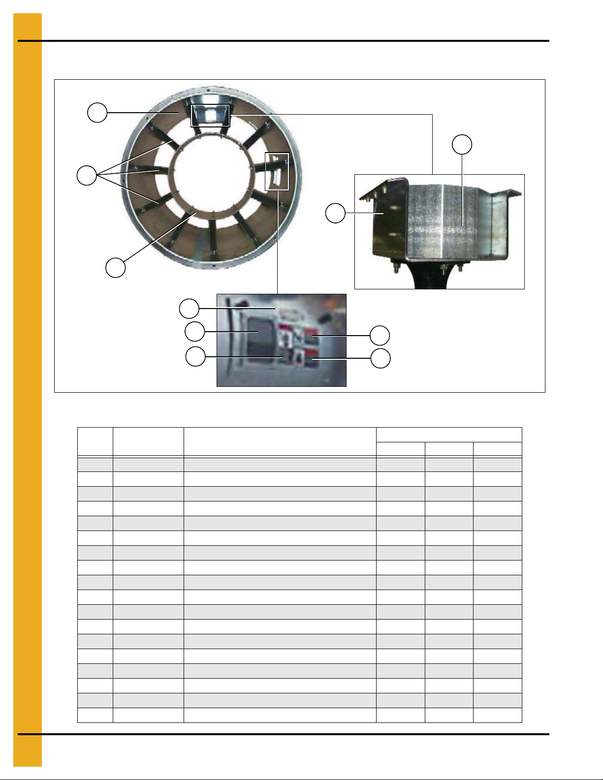
Fan/Heater Housing Assembly
Fan/Heater Housing Assembly Parts List
Ref # Part # Description
1 TF-1722 Wrapper 36" Fan/Heater 1
1 TF-1724 Wrapper 40" Fan/Heater 1
1 TF-1723 Wrapper 42" Fan/Heater 1
2 D01-1452 Straightening Vane, 36"-42" Fan/Heater 11 11 11
3 D01-1480 Inner Can, 36" Fan/Heater 1
3 D01-1479 Inner Can, 40" Fan/Heater 1
3 D01-1451 Inner Can, 42" Fan/Heater 1
4 HF-6062 Heater Access Panel 1 1 1
5 HF-7380 Window Access 0.060 x 6 x 6 Plastic 1 1 1
6 DC-1224 Decal, Danger High Voltage 1 1 1
7 DC-1225 Decal, Warning Rotating Blade 1 1 1
8 DC-1227 Decal, Warning Fire 1 1 1
9 D01-1484 Collector Cup, 36" Fan/Heater 1
9 D01-1485 Collector Cup, 40" Fan/Heater 1
9 TF-1217 Collector Cup, 42" Fan/Heater 1
10 D01-1482 Support Bracket, 36" Fan/Heater 1
10 D01-1483 Support Bracket, 40" Fan/Heater 1
10 TF-1216 Support Bracket, 42" Fan/Heater 1
3615 4015 4230-40
Qty
4 PNEG-1649 Top Dry
Page 5
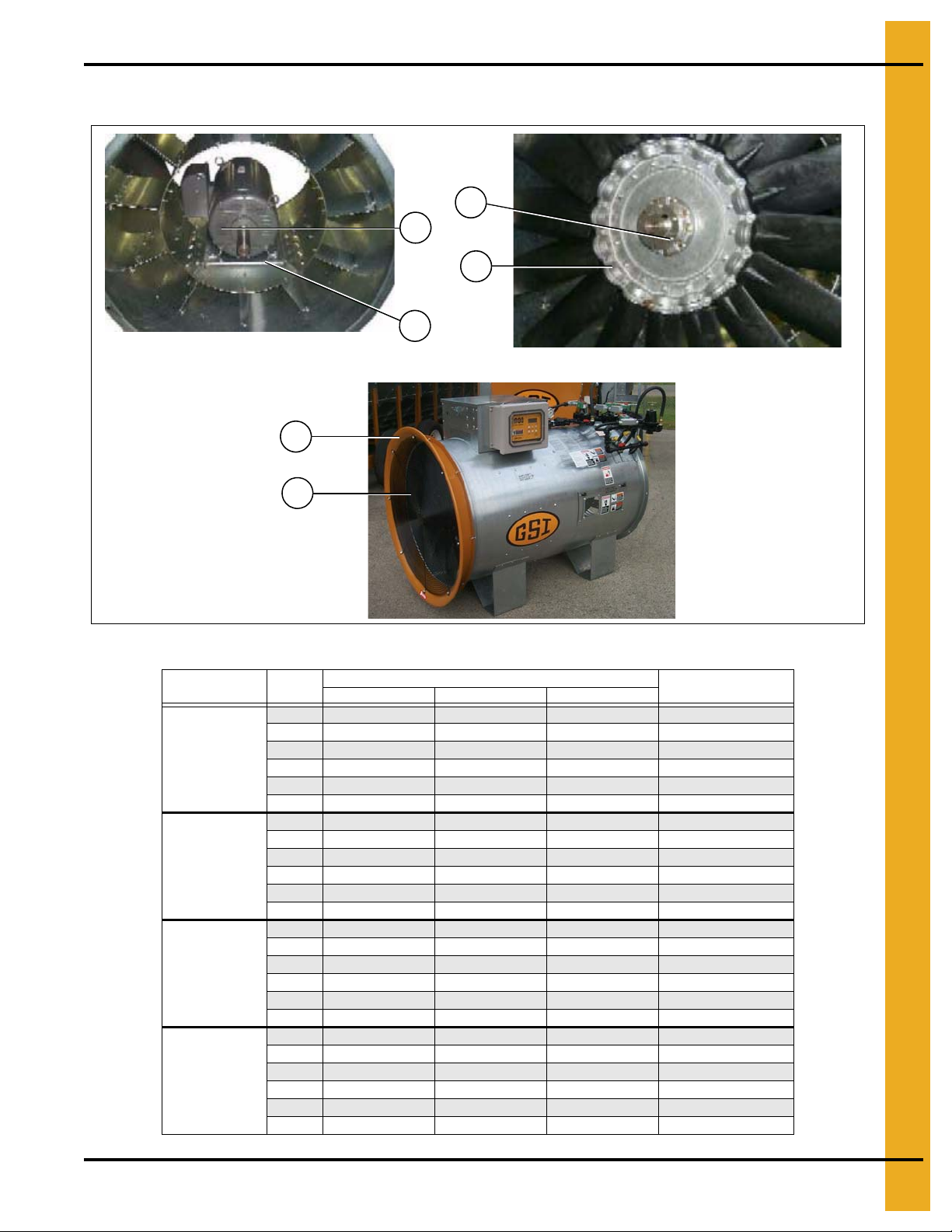
Fan Motor, Motor Mount and Fan Blade
Fan motor and motor mount
Fan blade and bushing
2
3
4
5
6
1
1. Parts List
Fan/Heater
Diameter HP
36" 15 HP
40" 15 HP
42" 30 HP
42" 40 HP
Fan Motor, Motor Mount and Fan Blade Parts List
Ref #
1 D01-1478 D01-1478 D01-1478 Motor Mount
2 C-7815 CH-1050 CH-1050 Motor
3 D82-0002 D82-0002 D82-0002 Fan Blade
4 FH-1009 FH-6963 FH-6963 Bushing
5 CD-0543-Y CD-0543-Y CD-0543-Y Venturi
6 CD-0544 CD-0544 CD-0544 Grill Guard
1 D01-1481 D01-1481 D01-1481 Motor Mount
2 C-7815 CH-1050 CH-1050 Motor
3 D03-0567 D03-0567 D03-0567 Fan Blade
4 GC03810 GC03810 GC03810 Bushing
5 CD-0545-Y CD-0545-Y CD-0545-Y Venturi
6 CD-0547 CD-0547 CD-0547 Grill Guard
1 N/A D01-1474 D01-1474 Motor Mount
2 N/A TFH-2011 TFH-2011 Motor
3 N/A D01-0472 D01-0472 Fan Blade
4 N/A CE-00617 CE-00617 Bushing
5 CD-0546-Y CD-0546-Y CD-0546-Y Venturi
6 CD-0547 CD-0547 CD-0547 Grill Guard
1 N/A D01-1475 D01-1475 Motor Mount
2 N/A CH-6848 CH-6848 Motor
3 N/A D01-0473 D01-0473 Fan Blade
4 N/A PT0784 PT0784 Bushing
5 CD-0546-Y CD-0546-Y CD-0546-Y Venturi
6 CD-0547 CD-0547 CD-0547 Grill Guard
220V 1 PH 230V 3 PH 460V 3 PH
Part #
Description
PNEG-1649 Top Dry 5
Page 6
1. Parts List
1
5
2
3
4
Fan Burner
Fan Burner Parts List
Fan/Heater
Diameter HP
36" 15 HP
40" 15 HP
42" 30 HP
42" 40 HP
Ref #
1 HF-7207 N/A Vaporizer Coil
2 THF-3047 THF-3047 Burner Assembly
3 TF-1559-T TF-1559-T Flame Probe and Wire Assembly
4 TF-1558 TF-1558 Ignitor and Wire Assembly
5 HH-7056 N/A Burner Cone
1 HF-7183 N/A Vaporizer Coil
2 THF-3028 THF-3028 Burner Assembly
3 TF-1559-T TF-1559-T Flame Probe and Wire Assembly
4 TF-1558 TF-1558 Ignitor and Wire Assembly
5 HH-7056 N/A Burner Cone
1 HF-7251 N/A Vaporizer Coil
2 THF-3028 THF-3028 Burner Assembly
3 TF-1559-T TF-1559-T Flame Probe and Wire Assembly
4 TF-1558 TF-1558 Ignitor and Wire Assembly
5 HH-7056 N/A Burner Cone
1 HF-7319 N/A Vaporizer Coil
2 THF-3028 THF-3028 Burner Assembly
3 TF-1559-T TF-1559-T Flame Probe and Wire Assembly
4 TF-1558 TF-1558 Ignitor and Wire Assembly
5 HH-7056 N/A Burner Cone
LP Units Natural Gas Units
Part #
Description
6 PNEG-1649 Top Dry
Page 7

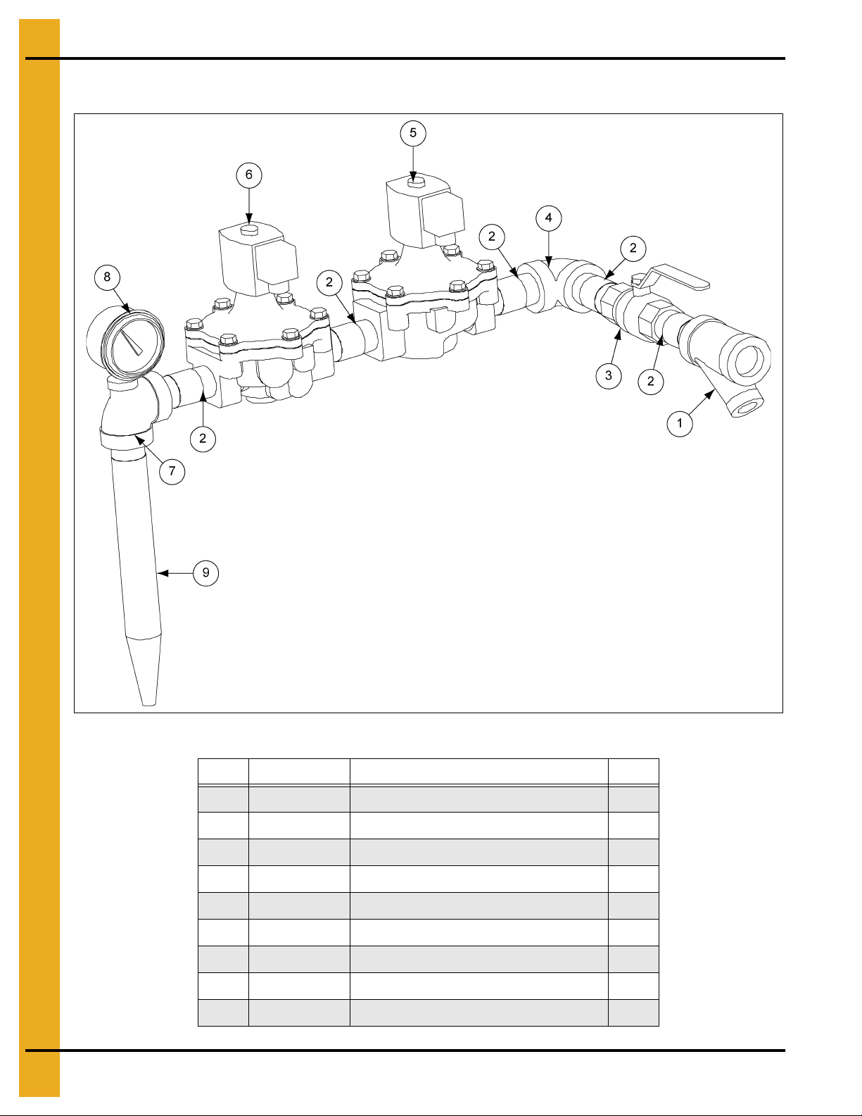
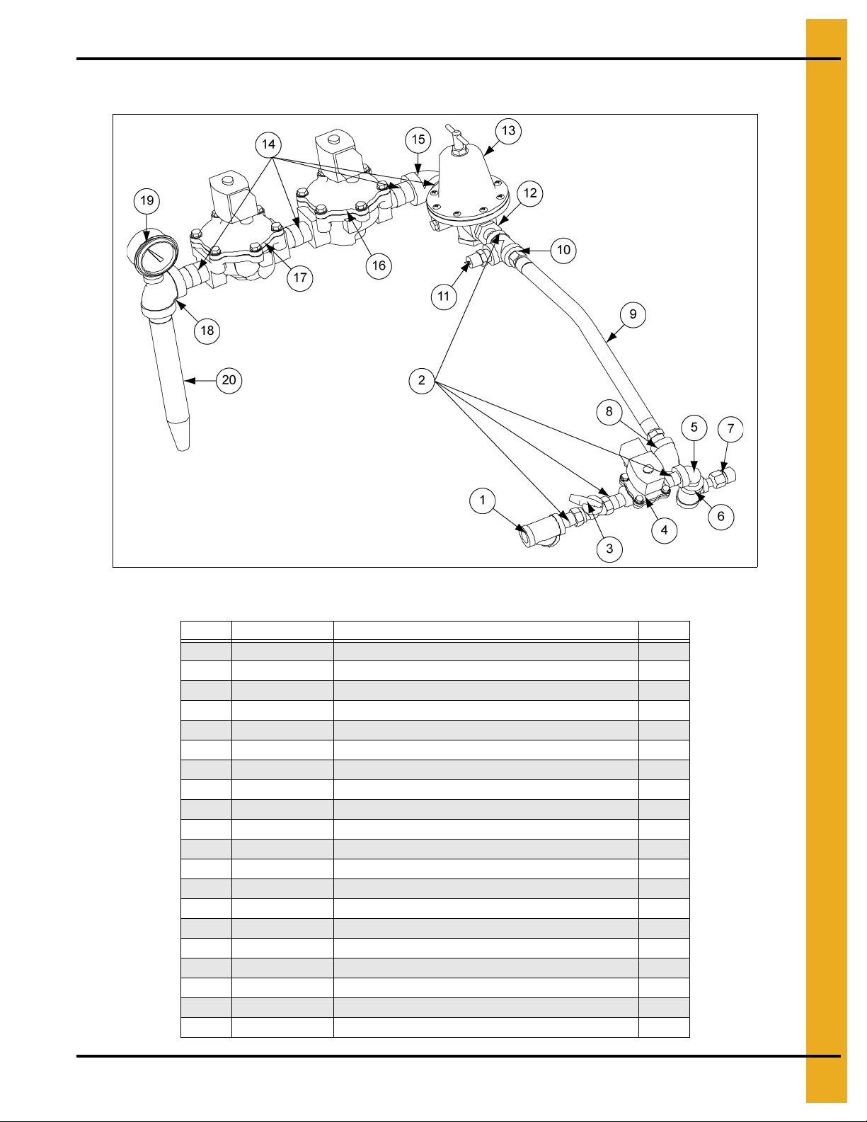
36" LP Gas Train (TF-1916)
1. Parts List
36" LP Gas Train (TF-1916) Parts List
Ref # Part # Description Qty
1 HH-1251 Strainer, 1/2" Y 250# WOG SCH 80 1
2 D07-0019 Nipple, 1/2" x 1-1/2" SCH 80 Black 4
3 TFC-0030 Valve, 1/2" NPT Ball-Bronze 1
4 TFC-0100 Valve, 1/2" NPT Solenoid LP with Din 1
5 HH-1082 Elbow, 1/2" - 90° Street SCH 80 Black 1
6 HH-4846 Tee, 1/2" x 1/2" x 1/4" SCH 80 Black 1
7 TFC-0027 Valve, 1/4" NPT 250# Relief 1
8 HH-4847 Elbow, 1/2" - 90° SCH 80 Black 1
9 HF-7509 Hose, 1/2" x 18" LP Gas Assembly 1
10 THH-4058 Tee, 1/2" x 1/2" x 1/2" SCH 80 Black 1
11 HH-7013 Switch Screw-In Vapor High-Limit 1
12 D07-0028 Reducer Bushing 1/2" x 3/4" 1
13 TFC-0020 Regulator, 3/4" (CSA) 1
14 THH-4125 Nipple, 3/4" x 2" SCH 40 Black 4
15 THH-4120 Elbow, 3/4" - 90° SCH 40 Black 1
16 056-2228-7 Solenoid Valve 3/4" NPT 115V Din with Bypass 1
17 056-2223-8 Solenoid Valve 3/4" NPT 115V Din 1
18 THH-4158 Tee, 3/4" x 1/4" x 3/4" SCH 40 Black 1
19 HH-2984 Gauge 0-30# Pressure LP 1
20 CD-0150 Orifice Tube 36" 15 HP LP 21/64" 1
PNEG-1649 Top Dry 7
Page 8
1. Parts List
36" NG Gas Train (TF-1948)
36" NG Gas Train (TF-1948) Parts List
Ref # Part # Description Qty
1 TF-1283 Strainer, 1" Y 250# WOG SCH 80 Black 1
2 THH-4151 Nipple, 1" x 3" SCH 40 Black 1
3 TFC-0093 Ball Valve 1" with Lever Handle 1
4 THH-41 15 Elbow, 1" - 90° SCH 40 Black 1
5 056-2230-3 Solenoid Valve 1" NPT 115V Din 1
6 056-2224-6 Solenoid Valve 1" NPT 115V Din 1
7 THH-4163 Tee, 3/4" x 1/4" x 3/4" SCH 40 Black 1
8 D08-0022 Gauge 0-15# Pressure LP 1
9 THF-3244 Orifice Tube 36" 10-16 HP Natural 1
8 PNEG-1649 Top Dry
Page 9
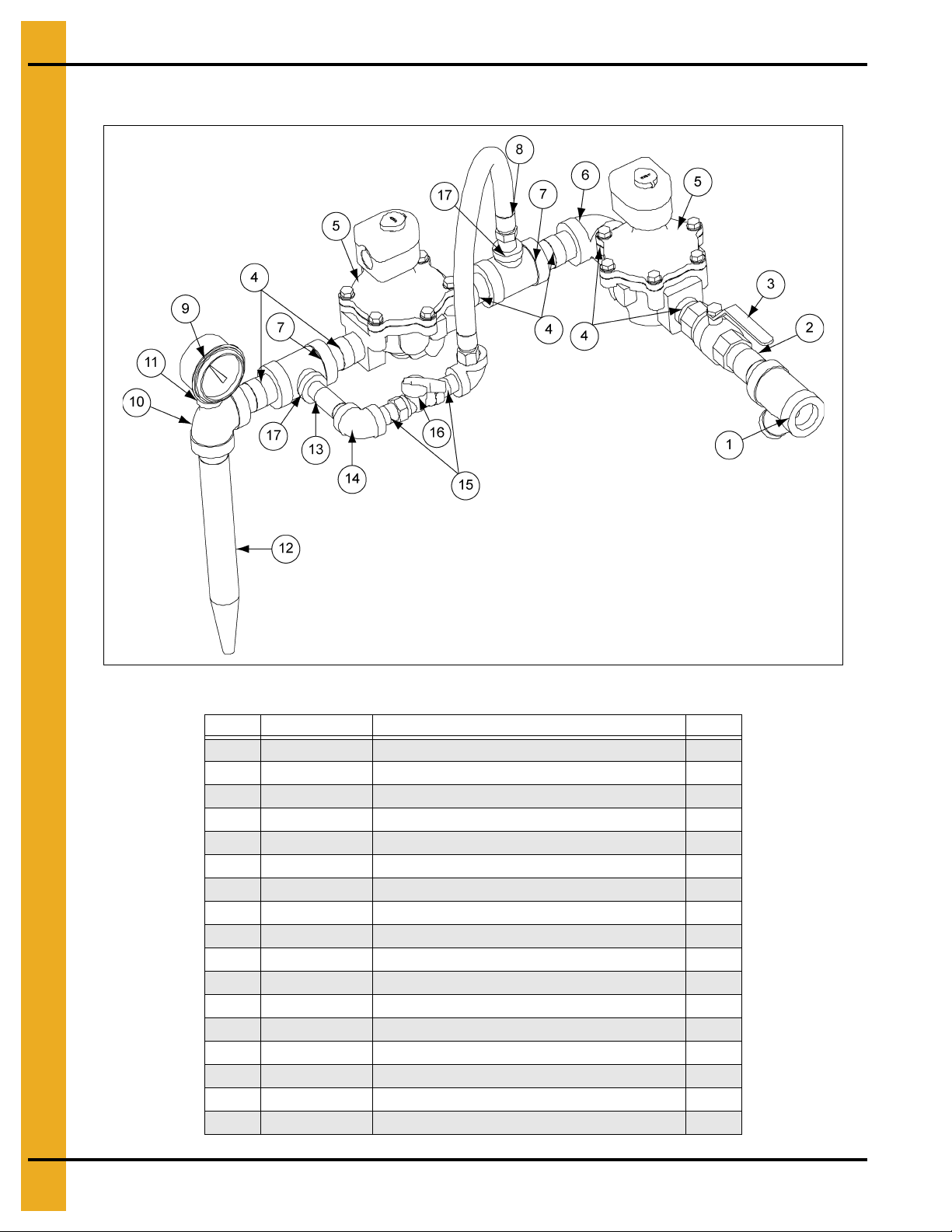
40" - 42" LP Gas Train (TF-1915)
1. Parts List
40" - 42" LP Gas Train (TF-1915) Parts List
Ref # Part # Description Qty
1 HH-1251 Strainer, 1/2" Y 250# WOG SCH 80 1
2 D07-0019 Nipple, 1/2" x 1-1/2" SCH 80 Black 4
3 TFC-0030 Valve, 1/2" NPT Ball-Bronze 1
4 TFC-0100 Valve, 1/2" NPT Solenoid LP with Din 1
5 HH-1082 Elbow, 3/4" - 90° Street SCH 40 Black 1
6 HH-4846 Tee, 1/2" x 1/2" x 1/4" SCH 80 Black 1
7 TFC-0027 Valve, 1/4" NPT 250# Relief 1
8 HH-4847 Elbow, 1/2" - 90° SCH 80 Black 1
9 HF-7509 Hose, 1/2" x 18" LP Gas Assembly 1
10 THH-4058 Tee, 1/2" x 1/2" x 1/2" SCH 80 Black 1
11 HH-7013 Switch Screw-In Vapor High-Limit 1
12 THH-4005 Reducer, 1" x 1/2" Hex Bushing SCH 40 1
13 TFC-0021 Regulator, 1" (CSA) 1
14 THH-4037 Nipple, 1" x 3" SCH 40 Black 4
15 THH-41 15 Elbow, 1" - 90° SCH 40 Black 1
16 056-2230-3 Solenoid Valve 1" NPT 115V Din 1
17 056-2224-6 Solenoid Valve 1" NPT 115V Din 1
18 THH-4163 Tee, 3/4" x 1/4" x 3/4" SCH 40 Black 1
19 HH-2984 Gauge 0-30# Pressure LP 1
20 THF-3059 Orifice Tube 40" LP 1
PNEG-1649 Top Dry 9
Page 10
1. Parts List
40" - 42" NG Gas Train (TF-1537)
40" - 42" NG Gas Train (TF-1537) Parts List
Ref # Part # Description Qty
1 D08-0015 Strainer, 1-1/2" Y SCH 80 Black 1
2 D08-0013 Nipple, 1-1/2" x 3" SCH 40 Black 1
3 D08-0008 Valve, 1-1/2" NPT B-Cock Shut Off 1
4 D08-0009 Nipple, 1-1/2" Close SCH 40 Black 6
5 TF-1536 Valve, 1-1/2" NPT Solenoid 2
6 D08-0011 Elbow, 1-1/2" - 90° SCH 40 Black 1
7 D38-0001 Tee, 1-1/2" x 1-1/2" x 1" SCH 40 Black 2
8 HF-7509 Hose, 1/2" x 18" LP Gas Assembly 1
9 D08-0022 Gauge 0-15# Pressure LP 1
10 D03-0445 Tee, 1-1/2" x 1" x 1-1/2" SCH 40 Black 1
11 THH-4001 Reducer, 1" x 1/4" Hex Bushing SCH 40 Black 1
12 THF-3251 Orifice Tube 42" 30 HP Natural Gas 1
13 D07-0023 Nipple, 1/2" x 3" SCH 80 Black 1
14 HH-4847 Elbow, 1/2" - 90° SCH 80 Black 2
15 D07-0019 Nipple, 1/2" x 1-1/2" SCH 80 Black 2
16 TFC-0030 Valve, 1/2" NPT Ball-Bronze 1
17 THH-4005 Reducer, 1" x 1/2" Hex Bushing SCH 40 2
10 PNEG-1649 Top Dry
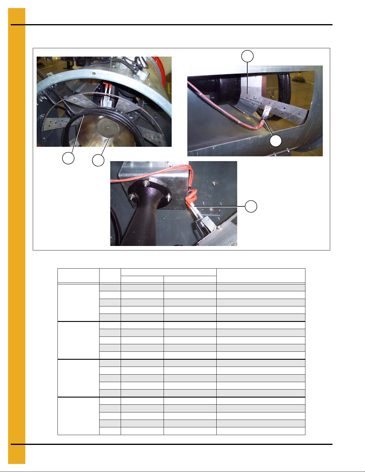
Page 11
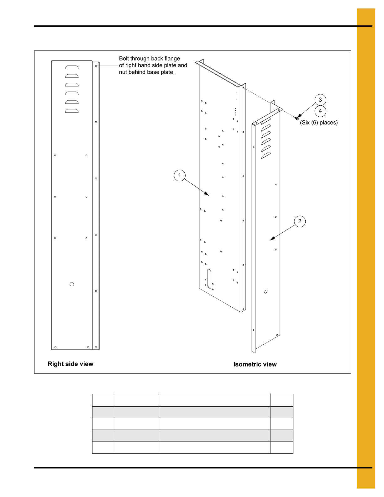
Actuator Housing
1. Parts List
Actuator Housing Parts List
Ref # Part # Description Qty
1 T AF-6061 Base Plate 1
2 TAF-6074 Right Hand Side Cover 1
3 S-6606 Flange Bolt 5/16"-18 x 3/4" ZN Grade 5 6
4 S-3611 Flange Nut 5/16"-18 YDP Grade 2 6
PNEG-1649 Top Dry 11
Page 12
1. Parts List
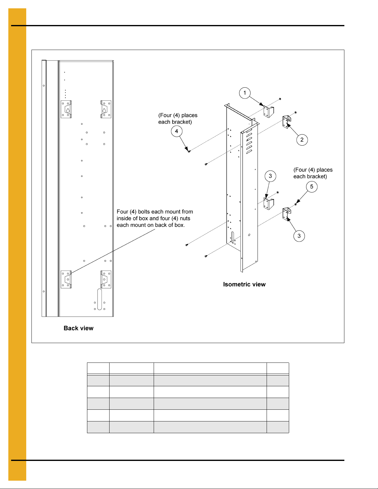
Actuator Housing (Continued)
Actuator Housing Parts List
Ref # Part # Description Qty
1 T AF-6160 Top Left Mount Bracket 1
2 T AF-6161 Top Right Mount Bracket 1
3 T AF-6032 Bottom Mount Bracket 2
4 S-6606 Flange Bolt 5/16"-18 x 3/4" ZN Grade 5 16
5 S-361 1 Flange Nut 5/16"-18 YDP Grade 2 16
12 PNEG-1649 Top Dry
Page 13
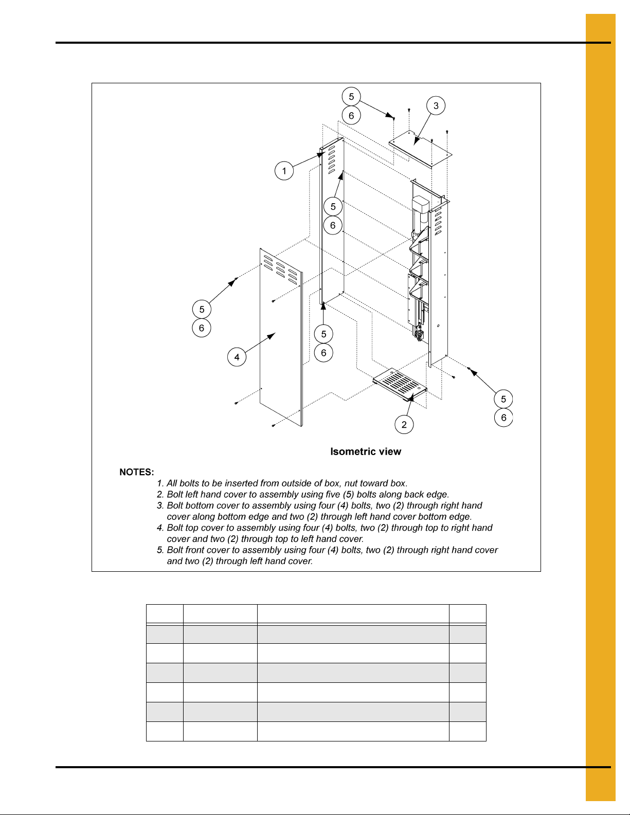
Actuator Housing (Continued)
1. Parts List
Actuator Housing Parts List
Ref # Part # Description Qty
1 T AF-6075 Left Hand Side Cover 1
2 TAF-6077 Bottom Cover 1
3 T AF-6076 Top Cover 1
4 TAF-6078 Front Cover 1
5 S-6606 Flange Bolt 5/16"-18 x 3/4" ZN Grade 5 17
6 S-3611 Flange Nut 5/16"-18 YDP Grade 2 17
PNEG-1649 Top Dry 13
Page 14
1. Parts List
Actuator Electrical
Actuator Electrical Parts List
Ref # Part # Description Qty
1 4557 Fuse, 15A, 250V, Fast Acting 4
2 70-0133 Connector, 1/4" Flly. Insul. Female 6
3 D01-0455 Lamp, Block Light 12/24/120V GE #090ADV for Use with Selector Switch 1
4 D01-0466 2 Position Switch Green 1
5 D01-0531 Terminal, Block Entrelec 4 mm 22-10 AWG 5
6 D01-0532 Terminal, Blank End Protector Grey Fem 6 1
7 D01-0533 Terminal, Entrelec End Stop 2
8 D03-0013 Din Rail x 6" Long 0.15
9 D63-0006 Block, Contact N.O. G.E. (Use D63-0006AB for Allen-Bradley) 2
10 DC-1337 Decal, Actuator 24V Power 1
11 FH-1058 Fuse Block 2
12 S-7416 #8-32 x 1/2" Self-Tapping Screw 6
13 TAF-6028 Lamp, 24 Volt 1
14 TD-100300 IDEC 2 PDT Relay 1
15 TD-100301 IDEC Relay Base 1
16 TFC-0048 Disconnect 1/4 Insul. Female CSA 6
14 PNEG-1649 Top Dry
Page 15
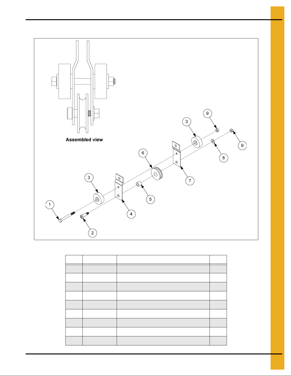
Actuator Guide Roller and Pulley
1. Parts List
Actuator Guide Roller and Pulley Parts List
Ref # Part # Description Qty
1 TF-1431 3/8"-16 x 3-3/4" HHCS Grade 2 1
2 S-7501 1/2" Shoulder Bolt w it h 3/ 8 " Th re ad 1
3 S-6999 Bearing Rack and Pinion Sealed 2
4 TAF-6064 Actuator Rod End To p 1
5 TF-1298 Bushing, Bronze 1/2" I.D. x 7/8" O.D. 1
6 TD-100021 Pulley, 2-1/2" x 0.874" Bore Rope 1
7 T AF-6065 Actuator Rod End Bottom 1
8 S-7409 Flat Washer 3/8" SAE ZN Grade 2 1
9 S-4663 Stover Nut 3/8"-16 ZN Grade 2 2
PNEG-1649 Top Dry 15
Page 16

1. Parts List
Actuator Stroke Guide Channel
Actuator Stroke Guide Channel Parts List
Ref # Part # Description Qty
1 T AF-6038 Angle Bracket for Actuator Guide 2
2 T AF-6039 C-Bracket for Actuator Guide 2
3 T AF-6037L Actuator Lower Guide 1
4 S-6606 Flange Bolt 5/16"-18 x 3/4" ZN Grade 5 8
5 S-361 1 Flange Nut 5/16"-18 YDP Grade 2 10
6 S-4275 Bolt, HHTB 5/16"-18 x 3/4" ZN Grade 5 2
16 PNEG-1649 Top Dry
Page 17

Actuator and Mount Hardware
1. Parts List
Actuator and Mount Hardware Parts List
Ref # Part # Description Qty
1 T AF-6011 Actuator 18" Stoke Linear 24 Volt 1
2 T AF-6066 Actuator Mounting Bracket 2
3 S-8135 Flange Bolt 5/16"-18 x 1-1/4" ZN Grade 5 4
4 S-1937 Flat Washer 5/16" ZN SAE Grade 2 4
5 S-361 1 Flange Nut 5/16"-18 YDP Grade 2 8
6 S-7501 1/2" Shoulder Bolt with 3/8" Thread 1
7 S-4663 Stover Nut 3/8"-16 ZN Grade 2 1
8 S-7409 Flat Washer 3/8" SAE ZN Grade 2 1
PNEG-1649 Top Dry 17
Page 18

1. Parts List
Actuator Bottom Pulley Assembly
Actuator Bottom Pulley Assembly Parts List
Ref # Part # Description Qty
1 TAF-6040 Left Hand Pulley Bracket 1
2 TAF-6041 Right Hand Pulley Bracket 1
3 S-7501 1/2" Shoulder Bolt with 3/8" Thread 2
4 TD-100021 Pulley, 2-1/2" x 0.874" Bore Rope 2
5 TF-1298 Bushing, Bronze 1/2" I.D. x 7/8" O.D. 2
6 S-7409 Flat Washer 3/8" SAE ZN Grade 2 2
7 S-4663 Stover Nut 3/8"-16 ZN Grade 2 2
8 TAF-6042 Cable Bracket 1
9 TD-100302 5/16" Jaw Type Forged Steel Swivel 1
10 S-6606 Flange Bolt 5/16"-18 x 3/4" ZN Grade 5 4
11 S-3611 Flange Nut 5/16"-18 YDP Grade 2 4
18 PNEG-1649 Top Dry
Page 19

Actuator Charger and Battery Shelves
1. Parts List
Actuator Charger and Battery Shelves Parts List
Ref # Part # Description Qty
1 S-6606 Flange Bolt 5/16"-18 x 3/4" ZN Grade 5 30
2 S-3611 Flange Nut 5/16"-18 YDP Grade 2 30
3 T AF-6068 Left Hand Shelf Bracket 3
4 T AF-6069 Battery and Charger Shelf 3
5 T AF-6073 Charger Side Strap 2
6 TAF-6072 Charger Top Strap 1
7 T AF-6071 Battery Side Strap 4
8 T AF-6070 Battery Top Strap 2
9 T AF-6016 24 Volt Battery Charger 1
PNEG-1649 Top Dry 19
Page 20

1. Parts List
Actuator Stroke Safety Cover
Actuator Stroke Safety Cover Parts List
Ref # Part # Description Qty
1 T AF-6037U Actuator Upper Guide 1
2 S-6606 Flange Bolt 5/16"-18 x 3/4" ZN Grade 5 5
3 S-361 1 Flange Nut 5/16"-18 YDP Grade 2 5
20 PNEG-1649 Top Dry
Page 21

C-Channel Installation
1. Parts List
Nominal Diameter
Center Collar Assembly
of Tank (ft.)
21' TD-100772
24' TD-100678
30' TD-100643
36' TD-100731
Part # “A”
Nominal Diameter
of Tank (ft.)
21' TD-100631
24' TD-100632
30' TD-100634
36' TD-100730
PNEG-1649 Top Dry 21
Part # “A”
Page 22

1. Parts List
Rafter Installation and Floor Support Angle Attachment
Nominal Diameter of
Tank (ft.)
21' TD-100777 TD-100778
24' TD-100720 TD-100721
30' TD-100650 TD-100651
36' TD-100740 TD-100741
Long Support Short Support
22 PNEG-1649 Top Dry
Page 23

Perforated Center Band
Nominal Diameter
of Tank (ft.)
# of Holes Dimension
21' 6 25-1/4"
24' 6 25-1/4"
30' 6 22"
36' 12 30"
1. Parts List
Nominal Diameter of
Tank (ft.)
21' TD-1SG545 3
24' TD-1SG545 3
30' TD-1SG545 3
PNEG-1649 Top Dry 23
36' TD-1SG226 6
Part # “A” Qty
Page 24

1. Parts List
Access Door Platform (TDP-5012)
Access Door Platform (TDP-5012) Parts List
Ref # Part # Description Weight Qty
1 LS-371 Platform Vertical Angle 42" 11.38 3
2 TDP-5000 Handrail 59" 10.15 2
3 TDP-5002 Hand rail 30" 10.15 2
4 TDP-5003 Handrail Brace 36-29/32" 6.34 2
5 TDP-5005 Flo or Brace 58-1/2" 26.11 3
6 TDP-5006 Platform Floor 37-7/8" 38.23 2
7 TDP-5007 Suppo rt Brace 50-21/32" 15.08 2
8 TDP-5008 Sidewall Brace 58" 19.65 2
9 TDP-5009 Platform Support 43-1/2" 12.95 2
10 TDP-5010 Platform Fl oor Splice 37-1/2" 6.24 1
11 TDP-5011 Platform Toe Plate 29-3/4" 3.29 1
12 TDP-5008N Sidewall Brace 2.66" 16.61 2
N/S TDP-5014 Access Door Package Hardware 5.41 1
24 PNEG-1649 Top Dry
Page 25

Large Platform Assembly for 42" Fan
1. Parts List
Large Platform Assembly for 42" Fan Parts List
Ref # Part # Description Weight Qty
1 TD-100085 Short Knee Brace 72-9/32" 54.51 2
2 TD-100086 Support Channel 98-3/8" 53.08 2
3 TD-100685 Vertical Support 94" 63.64 2
4 TD-100091 Large Platform Hardware Package 14.35 1
PNEG-1649 Top Dry 25
Page 26

1. Parts List
Cross Over Platform Assembly (for use with stairs) (TDP-5013)
Cross Over Platform Assembly (for use with stairs)
(TDP-5013) Parts List
Ref # Part # Description Weight Qty
1 LS-371 Platform Vertical Angle 42" 7.59 2
2 TDP-5001 Handrail 27" 4.63 2
3 TDP-5003 Handrail Brace 36-29/32" 6.34 2
4 TDP-5004 Short Floor Brace 26-1/2" 11.85 3
5 TDP-5006 Platform Floor 37-7/8" 19.11 1
6 TDP-5007 Support Brace 50-21/32" 15.08 2
7 TDP-5008 Sidewall Brace 58" 19.65 2
8 TDP-5009 Platform Support 43-1/2" 12.95 2
N/S TDP-5015 Cross Over Platform Hardware Package 3.95 1
26 PNEG-1649 Top Dry
Page 27

Transition Installation (TR-4734)
As viewed from inside bin
1. Parts List
Transition Installation (TR-4734) Parts List
Part # Description Qty
S-275 5/16"-18 x 3/4" Bin Bolt Grade 5 125
S-280 #10-16 x 5/8" Self-Drilling Screw 10
S-3651 Tube Caulk - Gray Butyl #506-15 1
S-396 5/16"-18 Hex Nut Grade 2 125
S-7264 Spec Neoprene Seal Strip with ADH 10'
PNEG-1649 Top Dry 27
Page 28

1. Parts List
Transition Assembly (TR-4734)
Transition Assembly (TR-4734) Parts List
Ref # Part # Description
1 TR-4724-1 Transition Side
1 TR-4724-2 Transition Side
2 TR-4767 Transition Faceplate
3 TR-4726 Top Entrance Collar Piece
4 TR-4727 Bottom Entrance Collar
5 TR-4728 Sizing Angle
6 TR-4729 Transition Bottom
7 TR-4730 Transition Top
8 TR-4731 Entrance Collar Side Bracket
28 PNEG-1649 Top Dry
Page 29

Top Dry Access Door Assembly (TD-100996)
1. Parts List
Top Dry Access Door Assembly (TD-100996) Parts List
Ref # Part # Description Qty
1 TD-100990 Access Door Plate 1
2 TD-100991 Access Top/Bottom Z-Frames 4
3 TD-100992 Access Door Side Z-Frames 4
4 TD-100993 Top Access Door 2
5 TD-100994 Inside Access Door 2
x TD-101020 Rear Door Catches 2
x TD-101021 Outside Door Latches 2
x TD-101022 Inside Door Latches 2
x D03-0512 Lockable Handle 2
x D02-0045 Gasket for Lockable Handle 2
x ACD-4513 Access Door Handle with Gasket 2
PNEG-1649 Top Dry 29
Page 30

1. Parts List
2 Ring Door Assembly
30 PNEG-1649 Top Dry
Page 31

2 Ring Door Assembly Parts List
1. Parts List
Part #
12'-27' Bin
Ref #
1 WD-039 WD-039 Outer Door Cover 1 1
2 WD-2854 WD-2854 Outer Cover Latch Bracket 2 2
3 WD-225 WD-225 Outer Cover Hinge Bracket 2 2
4 WD-035 WD-035 Door Cover Brace Section 4 4
5 WD-033 WD-033 Door Retainer 3 3
6 WD-6124 WD-6124 Outer Cover Latch Mount Base 2 2
7 WD-6066 WD-6066 Outer Cover Hinge Base 2 2
8 WD-6055 WD-6055 Bottom Inner Door Hinge 1 1
9 WD-6056 WD-6056 Middle Inner Door Hinge 2 2
10 WD-6054 WD-6054 Top Inner Door Hinge 1 1
11 S-4380 S-4380 Rubber Trim Seal Strip 2-1/4' 2-1/4'
12 WD-6039 WD-6039 Latch Bar 3 3
Diameter
4.00"
Corrugation
30'-60' Bin
Diameter
4.00"
Corrugation
Description
12'-27'
Diameter
Qty
30'-60'
Bin
Diameter
Bin
13 WD-6037 WD-6037 Inner Panel Latch - Right Hand 3 3
14 WD-6038 WD-6038 Inner Panel Latch - Left Hand 3 3
15 S-7160 S-7160 1/2" x 1" Hex Socket Cap Screw 6 6
16 WD-6040 WD-6040 Latch Bushing 6 6
17 WD-6079 WD-6079 Long Bearing Pin 38 38
18 WD-6125 WD-6125 Inner Panel Reinforcing Angle 6 6
19 WD-6128 WD-6128 Bottom Inner Door Panel 1 1
20 WD-6127 WD-6127 Middle Inner Door Panel 1 1
21 WD-6126 WD-6126 Top Inner Door Panel 1 1
22 WD-6028 WD-6028 Bottom Inner Door Port Hole Cover 1 1
23 WD-6053 WD-6053 Inner Door Hinge Strap 6 6
24 WD-1302 WD-1302 Door Hold Back Bracket 1 1
25 WD-6110 WD-6110 Door Hold Back Extension 1 1
PNEG-1649 Top Dry 31
Page 32

1. Parts List
NOTE: Use the following components of TAF-6097 to
attach assembly:
1. TAF-6107 Coupler aligned with holes in TAF-6173
and TAF-6086.
2. Use S-7241 (2) to attach TAF-6107 to TAF-6173
and TAF-6086.
3. Use supplied 1/8" roll pins to attach TD-100075 to
TD-100076 and TAF-6173.
Rotary Switch Package 18'-24' High-Limit (TAF-6099)
Rotary Switch Package 18'-24' High-Limit (TAF-6099) Parts List
Ref # Part # Description Qty
1 TD-101107 Top Dry Chamber High-Limit Mount Weldment 1
2 TD-100106 Coupler, 1-1/4" SCH 40 Galvanized 1
3 TD-100076 Switch, Rotary Power Pack 1
4 TD-100075 Coupler, Rotary Switch 1
5 T AF-6173 Rotary Shaft Extension 1
6 T AF-6086 Paddle, Rotary Switch 1
32 PNEG-1649 Top Dry
7 T AF-6172 Shaft Guard 21', 24' 1
N/S T AF-6097 High/Low Limit Rotary Switch Hardware Package 1
Page 33

Rotary Switch Package 18'-36' Low-Limit (TAF-6100)
NOTE: Use the following components of TAF-6097 to
attach assembly:
1. TAF-6107 Coupler aligned with holes in TAF-6094
and TAF-6085.
2. Use S-7241 (2) to attach TAF-6107 to TAF-6094
and TAF-6085.
3. Use supplied 1/8" roll pins to attach TD-100075 to
TD-100076 and TAF-6094.
1. Parts List
Rotary Switch Package 18'-36' Low-Limit (TAF-6100) Parts List
Ref # Part # Description Qty
1 TD-100627 Rotary Switch Roof Mount Weldment 1
2 TD-100076 Switch, Rotary Power Pack 1
3 TD-100075 Coupler, Rot ary Switch 1
4 T AF-6094 Rotary Switch Shaft Extension 1
5 T AF-6085 Paddle, Rotary Switch 1
6 T AF-6093 Rotary Switch Shaft Guard 1
PNEG-1649 Top Dry 33
N/S T AF-6097 High/Low Limit Rotary Switch Hardware Package 1
Page 34

1. Parts List
NOTE: Use the following components of TAF-6097 to
attach assembly:
1. TAF-6107 Coupler aligned with holes in TAF-6175
and TAF-6086.
2. Use S-7241 (2) to attach TAF-6107 to TAF-6175
and TAF-6086.
3. Use supplied 1/8" roll pins to attach TD-100075 to
TD-100076 and TAF-6175.
Rotary Switch Package 27'-30' High-Limit (TAF-6101)
Rotary Switch Package 27'-30' High-Limit (TAF-6101) Parts List
Ref # Part # Description Qty
1 TD-101107 Top Dry Chamber High-Limit Mount Weldment 1
2 TD-100106 Coupler, 1-1/4" SCH 40 Galvanized 1
3 TD-100076 Switch, Rotary Power Pack 1
4 TD-100075 Coupler, Rotary Switch 1
5 TAF-6175 Rotary Shaft Extension 1
6 TAF-6086 Paddle, Rotary Switch 1
34 PNEG-1649 Top Dry
7 TAF-6174 Shaft Guard 30' 1
N/S T AF-6097 High/Low Limit Rotary Switch Hardware Package 1
Page 35

Rotary Switch Package 36' High-Limit (TAF-6103)
NOTE: Use the following components of TAF-6097 to
attach assembly:
1. TAF-6107 Coupler aligned with holes i n TAF-6088
and TAF-6086.
2. Use S-7241 (2) to attach TAF-6107 to TAF-6088
and TAF-6086.
3. Use supplied 1/8" roll pins to attach TD-100075 to
TD-100076 and TAF-6088.
1. Parts List
Rotary Switch Package 36' High-Limit (TAF-6103) Parts List
Ref # Part # Description Qty
1 TD-101107 Top Dry Chamber High-Limit Mount Weldment 1
2 TD-100106 Coupler, 1-1/4" SCH 40 Galvanized 1
3 TD-100076 Switch, Rotary Power Pack 1
4 TD-100075 Coupler, Rotary Switch 1
5 T AF-6088 Rotary Switch Shaft Extension 1
6 T AF-6086 Paddle, Rotary Switch 1
PNEG-1649 Top Dry 35
7 T AF-6176 Shaft Guard 36' 1
N/S TAF-6097 High/Low Limit Rotary Switch Hardware Package 1
Page 36

1. Parts List
Drying Chamber Overflow Rotary Switch (TAF-6105)
Drying Chamber Overflow Rotary Switch (TAF-6105) Parts List
Ref # Part # Description Qty
1 TD-100627 Rotary Switch Roof Mount Weldment 1
2 TD-100076 Switch, Rotary Power Pack 1
3 TD-100075 Coupler, Rot ary Switch 1
4 T AF-6086 Paddle, Rotary Switch 1
N/S T AF-6096 Roof Mount Rotary Switch Hardware Package 1
36 PNEG-1649 Top Dry
Page 37

Wall Mount Rotary Switch Package (TAF-6106)
1. Parts List
Wall Mount Rotary Switch Package (TAF-6106) Parts List
Ref # Part # Description Qty
1 TD-100629 Sidewall Mount Weldment 1
2 TD-100076 Switch, Rotary Power Pack 1
3 TD-100075 Coupler, Rotary Switch 1
4 T AF-6085 Paddle, Rotary Switch 1
N/S TAF-6095 Wall Mount Rotary Switch Hardware Package 1
PNEG-1649 Top Dry 37
Page 38

1. Parts List
Small Platform Assembly for 36" Fan (TD-100092)
Small Platform Assembly for 36" Fan (TD-100092) Parts List
Ref # Part # Description Weight Qty
1 TD-100686 Vertical Support 70" 43.11 2
2 TD-100083 Support Channel 80-7/8" 32.98 2
3 TD-100084 Knee Brace 83-5/8" 23.67 2
38 PNEG-1649 Top Dry
Page 39

NOTES
PNEG-1649 Top Dry 39
Page 40

1. Parts List
NOTE: The following hardware is used to attach
components of the assembly:
1. S-7232 (9) Attaches 111-1001-2 to TF-1469 through
TF-1497
2. S-6521 (9) Attaches 111-1001-2 to TF-1714
3. S-6521 (4) Attaches TF-1519 (2) to TF-1714
4. D02-0036 Seals D01-0219 to TF-1498
5. D02-0049 Attached to TF-1498 for door seal.
Use CH-6873 to attach.
6. S-2052 Attached to TF-1714 for door seal.
Use CH-6873 to attach.
Control Box Assembly (TF-1270)
40 PNEG-1649 Top Dry
Page 41

1. Parts List
Control Box Assembly (TF-1270) Parts List
Ref # Part # Description Qty
1 TF-1492 Control Box Body, Top Dry Manual Control Center 1
2 TF-1490 Control Box Top 1
3 TF-1491 Control Box Bottom 1
4 TF-1258 Dummy Panel 1
5 TF-1494 Side Doo r Stop Angle 1
6 TF-1493 Top Door Stop Angle 1
7 TF-1495 Bottom Door Stop Angle 1
8 TF-1496 Hinge Side Door Stop Angle 1
9 S-8680 Flange Bolt 1/4"-20 x 3/4" ZN Grade 5 28
10 S-7215 Flange Nut 1/4"-20 ZN 28
11 S-2789 Screw, TCSF #8-32 x 1/2" PHP ZN 18
12 TF-1497 Hinge Body Segment 1
13 111-1001-2_18 Hinge 1-1/6" x 19 Gauge x 72" 1
14 TF-1714 Fill System Control Box Front Pan el 1
15 TF-1519 Latch, Southco Slotted 2
16 FH-4429-1 Clasp Assembly 2
17 TF-1257 Box Mounting Bracket 2
18 D01-0509 Hinge Body Segment 2
19 D01-0508 Hinge Door Segment 2
20 TF-1498 Monitor Control Box Door-TDMCC 1
21 D01-0219 Control Box Window 1
22 TFH-2048 Plug 7/8" Diameter Hole 3
23 HH-2833 Plug, 1/2" 1
24 D03-0013 Din Rail x 6" Long 1
25 D01-0533 Terminal, Entrelec End Stop 2
26 D01-0531 Terminal, Block Entrelec 4 mm 22-10 AWG 11
27 D01-0532 Terminal, Blank End Protector Grey Fem 6 1
28 D63-0013 Block, Contact N.C. G.E. (Use D63-0013AB for Allen-Bradley) 1
N/S S-7232 Rivet, POE 1/8" Diameter x 0.650" Long SRSM 0.438-0.500 9
N/S S-6251 Rivet, POE 1/8" Diameter x 0.375" Long ARSM 0.188-0.250 13
N/S D02-0036 Strip, Weather Window 5'
N/S D02-0049 Seal, 1/4" Thick x 3/4" Width 6'
N/S S-2052 Strip, Foam 1/8" Thick x 1/2" Wide Weather in Rolls 75' per Roll 6'
Door Hardware Parts List
Ref # Part # Description Qty
N/S S-3550 Carriage Bolt 5/16"-18 x 1" ZN Grade 5 6
N/S S-1463 Washer EPDM 5/16" Steel Backed 6
N/S S-7382 Nylock Nut 5/16"-18 ZN Grade 5 8
N/S S-4275 Bolt, HHTB 5/16"-18 x 3/4" ZN Grade 5 2
PNEG-1649 Top Dry 41
Page 42

1. Parts List
1
3
5
2
5
4
6
7
8
1
12
15
17
11
11-36 Pieces
10
14
16
19
19
Control Box Parts
42 PNEG-1649 Top Dry
Page 43

Control Box Parts (Continued)
18
18
13
9
9
13
13
9
13
13
9
13
13
9
13
13
9
13
13
9
13
13
9
13
9
13
13
1. Parts List
Series 2K Top Dry Control Panel Parts List
Ref # Part # Description Qty
1 D01-0444 Switch, 2 Position Selector Amber 080SMLDA GE 2
2 D01-0445 Switch, 3 Position Selector Amber 080SMLBA GE 1
3 D01-0446 Switch, 2 Position Selector Green 080SMLDV GE 1
4 D01-0447 Switch, 3 Position Selector Red 080SMLBR 1
5 D01-0449 Switch, 3 Position Selector Blue 080SMLBBL GE 2
6 D01-0579 Switch, 3 Position Selector Yellow 080SMLBG GE 1
7 D03-0017 Switch, Start N.O. (Illuminated) P9CPLVGD GE 1
8 D03-0020 Switch, Stop Block (Red) P9CPNRS GE 1
9 D01-0455 Lamp, Block Light 12/24/120V GE #090ADV for Use with Selector Switch 1
10 D01-0460 Terminal, Strip 10 Position Computer BDS EBY#EB1558A-10 or Equiv. CSA 18
11 D01-0531 Terminal, Block Entrelec 4 mm 22-10 AWG 36
12 D03-0682 Lamp, 120 VAC Replaces Both 120V and 12V Bulbs 9
13 D63-0006 Block, Contact N.O. G.E. (Use D63-0006AB for Allen-Bradley) 16
14 D63-0013 Block, Contact N.C. G.E. (Use D63-0013AB for Allen-Bradley) 1
15 TAF-6150 Panel, Touch Top Dry Auto - Keypad 1
16 TF-1279 Switch, Emergency Stop Operator 080TER Emergency Stop/2 N.C. GE 230V 1
16 TF-1486 Plate, Emergency Stop Switch 080N2RP009 GE (N/S) 1
17 TF-1862 Top Dry S2000 I/O Board with Software 1
18 TF-1863 Top Dry S2000 Display Board with Software 1
19 TFH-2021 Lamp, Red Light (No Leads) 4
PNEG-1649 Top Dry 43
Page 44

1. Parts List
Control Box Parts (Continued)
44 PNEG-1649 Top Dry
Page 45

1. Parts List
36" Fan Control Parts List
Qty
Ref
#
Part # Description
EBTF-
3615-1
EBTF-
3615-
3
EBTF-
3615-
EBTF-
3615-
4
1 D03-0485 Overload Relay, IEC 64-82A RT22J CLS20 1
1 D03-0482 Overload Relay, IEC 30-43A RT22E CLS20 1
1 D03-0477
Overload Relay, IEC 22A CLS20 RT12T Range
17.5-22.0 Amps Repl.
1
1 D03-0476 Overload Relay, IEC 18A CLS20 RT12S 1
1 D03-0479 Overload Relay, IEC 32A CLS20 RT12V 1
2 D03-0497 Relay, IEC 3 Pole 80A CL09 #CL09A311MJ 1
2 D03-0494 Relay, IEC 3 Pole 48A CL06 #CL06A311MJ 1
2 D03-0491 Relay, IEC 3 Pole 22A CL25 #CL25A310TJ 1
2 D03-0492 Relay, IEC 3 Pole 32A CL04 #CL04A310MJ 1 1
3 FH-3807 Transformer, 1/2 KVA 240/480 110V 1 1 1
3 HF-7566
Transformer, 380>575/120-240 0.5 380-460-575V/
120-240V 500VA GE#
4 D03-0559 Fuse Block, Entrelec Entrelec # 199.095.13 1 1 1 1 1
5 FH-1059 Fuse, 5A 1 1 1 1 1
6 D03-0562 Cover, Fuse Block Bussman Sami-7N 2 2 2 2 2
7 D36-0003 Fuse, Block Panel Mount 1 Fuse 2 2 2 2 2
8 D36-0002
Fuse, #FNQ5 500V Slow-Blow Buss #FNQ5 5 Amp
Slow-Blow Fuse
2 2 2 2 2
9 HH-1093 Transformer, 2 Pole Ignition 1 1 1
10 TF-1914
Switch, Start for C-7815 15 HP B Baldor Part, GE Brand,
GE# CR453CB2
1
11 D01-0531 Terminal, Block Entrelec 4 mm 22-10 AWG 33 33 33 33 33
EBTF-
3615-
5
1 1
6
40" Fan Control Parts List
Qty
Ref # Part # Description
1 D03-0485 Overload Relay, IEC 64-82A RT22J CLS20 1
1 D03-0482 Overload Relay, IEC 30-43A RT22E CLS20 1
1 D03-0477
1 D03-0476 Overload Relay, IEC 18A CLS20 RT12S 1
1 D03-0479 Overload Relay, IEC 32A CLS20 RT12V 1
2 D03-0497 Relay, IEC 3 Pole 80A CL09 #CL09A311MJ 1
2 D03-0494 Relay, IEC 3 Pole 48A CL06 #CL06A311MJ 1
2 D03-0491 Relay, IEC 3 Pole 22A CL25 #CL25A310TJ 1
2 D03-0492 Relay, IEC 3 Pole 32A CL04 #CL04A310MJ 1 1
3 FH-3807 Transformer, 1/2 KVA 240/480 110V 1 1 1
3 HF-7566
4 D03-0559 Fuse Block, Entrelec Entrelec # 199.095.13 1 1 1 1 1
5 FH-1059 Fuse, 5A 1 1 1 1 1
6 D03-0562 Cover, Fuse Block Bussman Sami-7N 2 2 2 2 2
7 D36-0003 Fuse, Block Panel Mount 1 Fuse 2 2 2 2 2
8 D36-0002
9 HH-1093 Transformer, 2 Pole Ignition 1 1 1
10 TF-1914
11 D01-0531 Terminal, Block Entrelec 4 mm 22-10 AWG 33 33 33 33 33
Overload Relay, IEC 22A CLS20 RT12T Range
17.5-22.0 Amps Repl.
Transformer, 380>575/120-240 0.5 380-460-575V/
120-240V 500VA GE#
Fuse, #FNQ5 500V Slow-Blow Buss #FNQ5 5 Amp
Slow-Blow Fuse
Switch, Start for C-7815 15 HP B Baldor Part, GE Brand,
GE# CR453CB2
EBTF-
4015-1
2 2 2 2 2
1
EBTF4015-3
EBTF-
4015-4
1
EBTF-
4015-5
1 1
EBTF4015-6
PNEG-1649 Top Dry 45
Page 46

1. Parts List
Control Box Parts (Continued)
46 PNEG-1649 Top Dry
Page 47

1. Parts List
4230 Fan Control Parts List
Qty
Ref # Part # Description
1 D03-0486 Overload Relay, IEC 97A CLS20 RT22L 1
1 D03-0485 Overload Relay, IEC 64-82A RT22J CLS20 1
1 D03-0482 Overload Relay, IEC 30-43A RT22E CLS20 1
1 D03-0481 Overload Relay, IEC 32A CLS20 RT22D 1
1 D03-0483 Overload Relay, IEC 42-55A RT22G CLS20 03/30/01 1
2 D03-0498 Relay, IEC 3 Pole 96A CL10 #CL10A311MJ 1
2 D03-0497 Relay, IEC 3 Pole 80A CL09 #CL09A311MJ 1
2 D03-0494 Relay, IEC 3 Pole 48A CL06 #CL06A311MJ 1 1
2 D03-0495 Relay, IEC 3 Pole 62A CL07 CL07A311MJ 1
3 FH-3807 Transformer, 1/2 KVA 240/480 110V 1 1 1
3 HF-7566 Transformer, 380>575/120-240 0.5 380-460-575V/120-240V 500VA GE# 1 1
4 D03-0559 Fuse Block, Entrelec Entrelec # 199.095.13 1 1 1 1 1
5 FH-1059 Fuse, 5A 1 1 1 1 1
6 D03-0562 Cover, Fuse Bl ock Bussman Sami-7N 2 2 2 2 2
7 D36-0003 Fuse, Block Panel Mount 1 Fuse 2 2 2 2 2
8 D36-0002 Fuse, #FNQ5 500V Slow-Blow Buss #FNQ5 5 Amp Slow-Blow Fuse 2 2 2 2 2
9 HH- 1093 Transformer, 2 Pole Ignition 1 1 1
11 D01-0531 Terminal, Block Entrelec 4 mm 22-10 AWG 33 33 33 33 33
EBTF4230-2
EBTF-
4230-3
EBTF-
4230-4
EBTF-
4230-5
EBTF4015-6
4240 Fan Control Parts List
Qty
Ref # Part # Description
1 056-2276-6 Overload Relay, 90-150A ADJ IEC 1
1 D03-0483 Overload Relay, IEC 42-55A RT22G CLS20 03/30/01 1
1 D03-0482 Overload Relay, IEC 30-43A RT22E CLS20 1
1 D03-0484 Overload Relay, IEC 65A CLS20 RT22H 1
2 D03-0495 Relay, IEC 3 Pole 62A CL07 CL07A311MJ 1
2 D03-0496 Relay, IEC 3 Pole 68A CL08 #CL08A311MJ 1
N/S 056-2072-9 Lug, for 150A Contactor 1
3 FH-3807 Transformer, 1/2 KVA 240/480 110V 1 1
3 HF-7566 Transformer, 380>575/120-240 0.5 380-460-575V/120-240V 500VA GE# 1 1
4 D03-0559 Fuse Block, Entrelec Entrelec # 199.095.13 1 1 1 1
5 FH-1059 Fuse, 5A 1 1 1 1
6 D03-0562 Cover, Fuse Block Bussman Sami-7N 2 2 2 2
7 D36-0003 Fuse, Block Panel Mount 1 Fuse 2 2 2 2
8 D36-0002 Fuse, #FNQ5 500V Slow-Blow Buss #FNQ5 5 Amp Slow-Blow Fuse 2 2 2 2
9 HH-1093 Transformer, 2 Pole Ignition 1 1 1
11 D01-0531 Terminal, Block Entrelec 4 mm 22-10 AWG 33 33 33 33
12 056-2275-8 Coil, Contactor 150A 110V IEC Vendor: SQD #LC1-D15000F7 1
13 056-1951-5 Relay, Aux 1 N.O. 1 N.C. IEC Side 1
EBTF4240-3
EBTF4240-4
EBTF-
4230-5
EBTF-
4015-6
PNEG-1649 Top Dry 47
Page 48

NOTES
48 PNEG-1649 Top Dry
Page 49

2. Warranty
9101239_1_CR_rev7.DOC (revised July 2009)
GSI Group, LLC Limited Warranty
The GSI Group, LLC (“GSI”) warrants products which it manufactures to be free of defects in materials and workmanship
under normal usage and conditions for a period of 12 months after sale to the original end-user or if a foreign sale,
14 months from arrival at port of discharge, whichever is earlier. The end-user’s sole remedy (and GSI’s only obligation)
is to repair or replace, at GSI’s option and expense, products that in GSI’s judgment, contain a material defect in materials
or workmanship. Expenses incurred by or on behalf of the end-user without prior written authorization from the GSI
Warranty Group shall be the sole responsibility of the end-user.
Warranty Extensions:
The Limited Warranty period is extended for the following products:
Product Warranty Period
Performer Series Direct Drive Fan Motor 3 Years
AP Fans and Flooring
Cumberland
Feeding/Watering
Systems
Grain Systems Grain Bin Structural Design 5 Years
Grain Systems
Farm Fans
Zimmerman
All Fiberglass Housings Lifetime
All Fiberglass Propellers Lifetime
Feeder System Pan Assemblies 5 Years **
Feed Tubes (1-3/4" and 2.00") 10 Years *
Centerless Augers 10 Years *
Watering Nipples 10 Years *
Portable and Tower Dryers 2 Years
Portable and Tower Dryer Frames and
Internal Infrastructure †
5 Years
* Warranty prorated from list price:
0 to 3 years - no cost to end-user
3 to 5 years - end-user pays 25%
5 to 7 years - end-user pays 50%
7 to 10 years - end-user pays 75%
** Warranty prorated from list price:
0 to 3 years - no cost to end-user
3 to 5 years - end-user pays 50%
† Motors, burner components
and moving parts not included.
Portable dryer screens included.
Tower dryer screens not included.
GSI further warrants that the portable and tower dryer frame and basket, excluding all auger and auger drive components,
shall be free from defects in materials for a period of time beginning on the twelfth (12
and continuing until the sixtieth (60
th
) month from the date of purchase (extended warranty period). During the extended
th
) month from the date of purchase
warranty period, GSI will replace the frame or basket components that prove to be defective under normal conditions
of use without charge, excluding the labor, transportation, and/or shipping costs incurred in the performance of this
extended warranty.
Conditions and Limitations:
THERE ARE NO WARRANTIES THAT EXTEND BEYOND THE LIMITED WARRANTY DESCRIPTION SET FORTH
ABOVE. SPECIFICALLY, GSI MAKES NO FURTHER WARRANTY OF ANY KIND, EXPRESS OR IMPLIED,
INCLUDING, WITHOUT LIMITATION, WARRANTIES OF MERCHANTABILITY OR FITNESS FOR A PARTICULAR
PURPOSE OR USE IN CONNECTION WITH: (I) PRODUCT MANUFACTURED OR SOLD BY GSI OR (II) ANY ADVICE,
INSTRUCTION, RECOMMENDATION OR SUGGESTION PROVIDED BY AN AGENT, REPRESENTA TIVE OR
EMPLOYEE OF GSI REGARDING OR RELATED TO THE CONFIGURATION, INSTALLATION, LAYOUT, SUITABILITY
FOR A PARTICULAR PURPOSE, OR DESIGN OF SUCH PRODUCTS.
GSI shall not be liable for any direct, indirect, incidental or consequential damages, including, without limitation, loss of
anticipated profits or benefits. The sole and exclusive remedy is set forth in the Limited Warranty, which shall not exceed
the amount paid for the product purchased. This warranty is not transferable and applies only to the original end-user. GSI
shall have no obligation or responsibility for any representations or warranties made by or on behalf of any dealer, agent
or distributor.
GSI assumes no responsibility for claims resulting from construction defects or unauthorized modifications to products
which it manufactured. Modifications to products not specifically delineated in the manual accompanying the equipment at
initial sale will void the Limited Warranty.
This Limited Warranty shall not extend to products or parts which have been damaged by negligent use, misuse, alteration,
accident or which have been improperly/inadequately maintained. This Limited Warranty extends solely to products
manufactured by GSI.
Prior to installation, the end-user has the responsibility to comply with federal, state and local codes which apply to the
location and installation of products manufactured or sold by GSI.
PNEG-1649 Top Dry 49
Page 50

This equipment shall be installed in accordance with
the current installation codes and applicable
regulations, which should be carefully followed in
all cases. Authorities having jurisdiction should be
consulted before installations are made.
Copyright © 2013 by GSI Group
Printed in the USA
GSI Group
1004 E. Illinois St.
Assumption, IL 62510-0020
Phone: 1-217-226-4421
Fax: 1-217-226-4420
www.gsiag.com
CN-304272
 Loading...