

Page 1

PNEG-163-08
Centrifugal Fan Installation
and Operation
Owner ’s Manual
PNEG-163-08
Date: 03-11-13
Page 2

Check List
1. All wire connections
2. Tip clearance on blade
3. Fan blade torqued to torque specs
4. Grill guard in place and tight
5. Fuse in place, extra fuse provided
6. Motor rotation correct
7. Contactor engages properly
8. Running amperage
9. Vibration
10. All fasteners tight
11. Indicator light
12. All decals and serial number tag
13. Aesthetic appearance
14. Manual
15. Manual supplements for double inlet fans
Model #:
Serial #:
Tester Signature:
Date:
2 PNEG-163-08 Centrifugal Fan
Page 3

Table of Contents
Contents
Chapter 1 Safety .....................................................................................................................................................5
Safety Guidelines ... ... ... ... ...................................................................................................................... 5
Safety Instructions ..................... ... .... .......................................... ... ... ... ... .... ........................................... 6
General Safety Statement ..................................................................................................................... 9
Chapter 2 Safety Decals ......................................................................................................................................10
Chapter 3 Installation ..........................................................................................................................................14
Pre-Installation Requirements .......................... ................................................ ................................... 14
Fan Installation .................................................................................................................................... 15
Electrical Installation ........................................................................................................................... 15
Test Run .............................................................................................................................................. 16
Ground Rod Installation ...................................................................................................................... 17
Chapter 4 Fan Specifications ..............................................................................................................................18
1750 RPM Fan Electrical Specifications ...... ....................................................................................... 18
3500 RPM Fan Electrical Specifications ...... .... .......................................... ... ... ... .... ... ... ... ... .... ... ... ...... 19
Fan Dimensions .................................................................................................................................. 20
Discharge Bolt Pattern Dimensions .................................................................................................... 21
Inlet Cone Dimensions ........................................................................................................................ 22
Fan Wheel Dimensions ....................................................................................................................... 23
Fan Pad Location ................................................................................................................................ 24
Chapter 5 Operation ............................................................................................................................................25
Fan Start-Up ........................................................................................................................................ 25
Fan Shut Down ................................................................................................................................... 25
Maintaining Grain Quality .................................................................................................................... 25
Grain Storage ............................... .... ... ... ... ... .... ... .......................................... ... ... .... ... ... ...................... 26
Chapter 6 User Servicing Instructions and Troubleshooting ..........................................................................27
Fan Wheel Removal and Installation .................................................................................................. 27
Fan Wheel Inspection and Maintenance ............................................................................................. 28
Taper-Lock Bushing Torque Requirements ........................................................................................ 29
Fan Motor Removal and Installation ................................................................................................... 29
General Inspection .............................................................................................................................. 29
Lubrication and Bearings .................................................................................................................... 30
Troubleshooting Charts ....................................................................................................................... 31
Chapter 7 Parts List .............................................................................................................................................33
Main Assembly - 1750 RPM Fans ....................................................................................................... 34
Main Assembly - 3500 RPM Fans ....................................................................................................... 39
Main Assembly - Single Inlet Direct Drive Fan .................................................................................... 44
Main Assembly - Double Inlet Fan ...................................................................................................... 45
Internal Bearing Arch Assembly - Double Inlet Fan ............................................................................ 46
Motor Drives - Double Inlet Fan .......................................................................................................... 47
Shaft Coupling ..................................................................................................................................... 48
Small Control Panel 1 Phase 230 Volt (CPS-230-1) ........................................................................... 50
Small Control Panel 3 Phase 230 Volt (CPS-230-3) ........................................................................... 52
Large Control Panel 3 Phase 230 Volt (CPL-230-3) ........................................................................... 54
Small Control Panel 3 Phase 380V, 460V and 575V (CPS-345-3) ............... ...................................... 56
Large Control Panel 3 Phase 460V and 575V (CPL-345-3) ............................................................... 58
Motor Conduit Assembly ..................................................................................................................... 60
PNEG-163-08 Centrifugal Fan 3
Page 4

Table of Contents
Chapter 8 Schematics/Wiring Diagrams ............................................................................................................66
Wiring Schematic - 230 Volt 1 Phase .................................................................................................. 66
Wiring Diagram - CHS-3-1C ................................................................................................................ 68
Wiring Diagram - CF-10-1C and CHS-10-1C ...................................................................................... 69
Wiring Diagram - CF-15-1C ................................................................................................................ 70
Wiring Diagram - CF-5-1C, CF-7.5-1C, CHS-5-1C and CHS-7.5-1C .................................................. 71
Wiring Schematic - 230 Volt 3 Phase .................................................................................................. 72
Wiring Diagram - 230 Volt 3 Phase ..................................................................................................... 73
Wiring Schematic - 460 Volt 3 Phase .................................................................................................. 74
Wiring Diagram - 460 Volt 3 Phase ..................................................................................................... 75
Chapter 9 Appendix A .........................................................................................................................................76
Double Inlet Fans ................................................................................................................................ 76
Chapter 10 Warranty ............................................................................................................................................77
4 PNEG-163-08 Centrifugal Fan
Page 5
1. Safety
DANGER
WARNING
CAUTION
NOTICE
This is the safety alert symbol. It is used to alert you
to potential personal injury hazards. Obey all safety
messages that follow this symbol to avoid possible
injury or death.
WARNING indicates a hazardous situation which, if not
avoided, could result in death or serious injury.
CAUTION, used with the safety alert symbol, indicates a
hazardous situation which, if not avoided, could result in
minor or moderate injury.
NOTICE is used to address practices not related to
personal injury.
DANGER indicates a hazardous situation which, if not
avoided, will result in death or serious injury.
Safety Guidelines
This manual contains information that is important for you, the owner/operator, to know and understand.
This information relates to protecting personal safety and preventing equipment problems. It is the
responsibility of the owner/operator to inform anyone operating or working in the area of this equipment
of these safety guidelines. To help you recognize this information, we use the symbols that are defined
below. Please read the manual and pay attention to these sections. Failure to read this manual and its
safety instructions is a misuse of the equipment and may lead to serious injury or death.
PNEG-163-08 Centrifugal Fan 5
Page 6
1. Safety
Follow Safety Instructions
Carefully read all safety messages in this manual and
safety signs on your machine. Keep signs in good
condition. Replace missing or damaged safety signs. Be
sure new equipment components and repair parts include
the current safety signs. Replacement safety signs are
available from the manufacturer.
Learn how to operate the machine and how to use controls
properly. Do not let anyone operate without instruction.
Keep your machinery in proper working condition.
Unauthorized modifications to the machine may impair
the function and/or safety and affect machine life.
If you do not understand any part of this manual or need
assistance, contact your dealer.
Read and Understand Manual
Practice Safe Maintenance
Understand service procedures before doing work. Keep area
clean and dry.
Never lubricate, service, or adjust machine while it is in operation.
Keep hands, feet, and clothing away from rotating parts.
Keep all parts in good condition and properly installed. Fix
damage immediately . Replace worn or broken p arts. Remove any
built-up grease, oil, and debris.
Maintain Equipment
and Work Area
Safety Instructions
Our foremost concern is your safety and the safety of others associated with this equipment. We want to
keep you as a customer. This manual is to help you understand safe operating procedures and some
problems which may be encountered by the operator and other personnel.
As owner and/or operator, it is your responsibility to know what requirements, hazards, and precautions
exist, and to inform all personnel associated with the equipment or in the area. Safety precautions may be
required from the personnel. Avoid any alterations to the equipment. Such alterations may p roduce a very
dangerous situation where SERIOUS INJURY or DEATH may occur.
This equipment shall be installed in accordance with the current installation codes and applicable
regulations which should be carefully followed in all cases. Authorities having jurisdiction should be
consulted before installations are made.
6 PNEG-163-08 Centrifugal Fan
Page 7
1. Safety
Install and Operate Electrical Equipment Properly
Electrical controls should be installed by a qualified electrician
and must meet the standards set by the National Electrical Code
and all local and state codes.
Disconnect and lock out all power sources before installing
wires/cables or servicing equipment.
Electric Shock Hazard
Install and Operate Gas-Fired Equipment Properly
Fuel supply should be installed by a qualified gas
technician and must meet local and state codes for
gaseous fuel supplies.
Disconnect and lock out all fuel sources before
servicing equipment.
Explosive Gases
Prepare for Emergencies
Be prepared if fire starts.
Keep a first aid kit and fire extinguisher handy.
Keep emergency numbers for doctors, ambulance service,
hospital, and fire department near your telephone.
Keep Emergency Equipment
Quickly Accessible
PNEG-163-08 Centrifugal Fan 7
Page 8
1. Safety
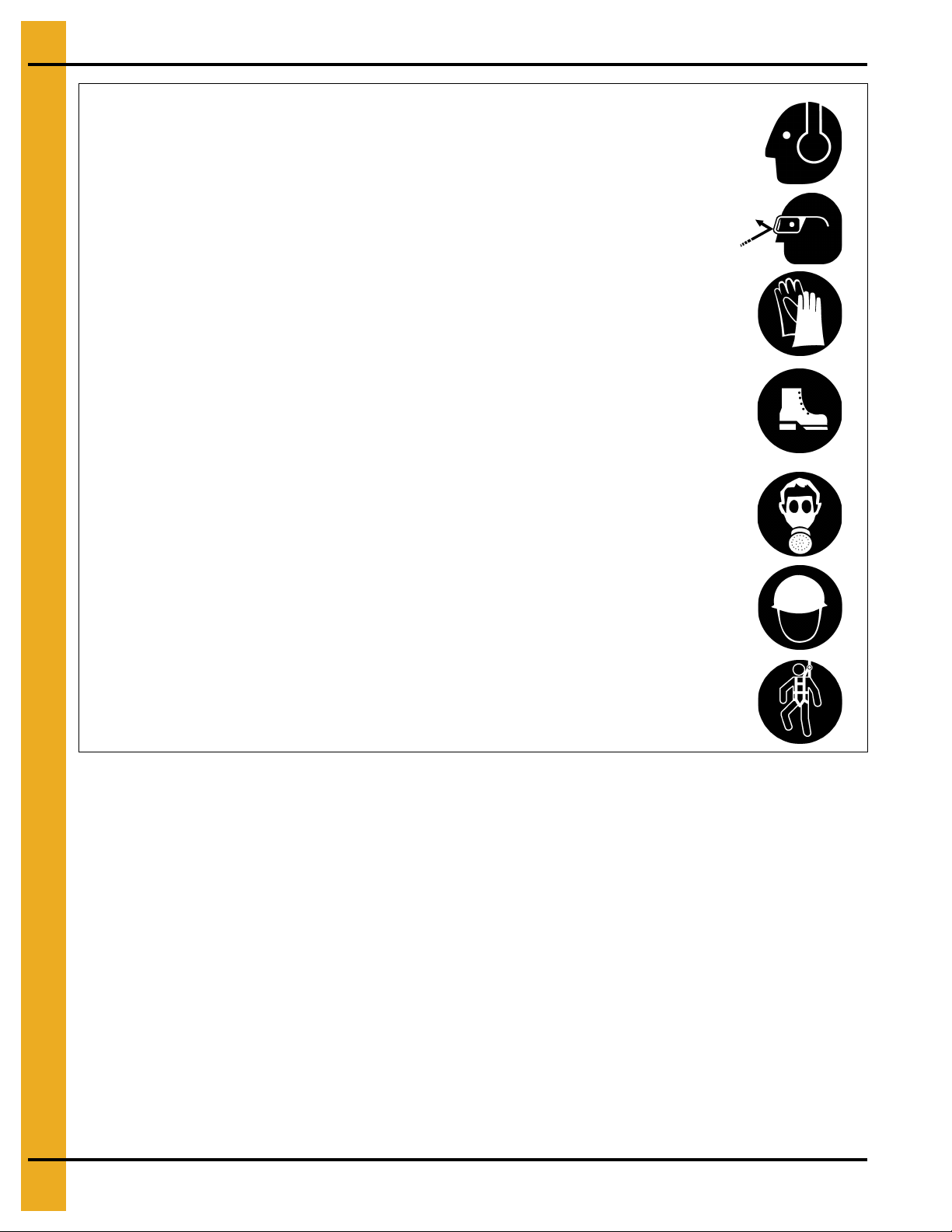
Wear Protective Clothing
Ear plugs or muffs should be worn at all times to protect ears
from high noise levels.
Wear close-fitting clothing and safety equipment appropriate
to the job.
Remove all jewelry.
Tie long hair up and back.
Wear safety glasses at all times to protect eyes from debris.
Wear gloves to protect your hands from sharp edges on plastic
or steel parts.
Wear steel-toed boots to help protect your feet from falling
debris. Tuck in any loose or dangling shoestrings.
A respirator may be needed to prevent breathing potentially
toxic fumes and dust.
Wear a hard hat to help protect your head.
Wear appropriate fall protection equipment when working at
elevations greater than six feet (6').
Eye Protection
Gloves
Steel-Toed Boots
Respirator
Hard Hat
Fall Protection
Hearing Protection
8 PNEG-163-08 Centrifugal Fan
Page 9
1. Safety
This product has sharp edges, which may cause serious injury. To avoid injury, handle
sharp edges with caution and always use proper protective clothing and equipment.
General Safety Statement
Our foremost concern is your safety and the safety of others associated with grain handling equipment.
This manual is to help you understand safe operating procedures and some problems which may be
encountered by the operator and other personnel.
As owner and/or operator, you are responsible to know what requirements, hazard s, and precautions exist
and inform all personnel associated with the equipment or in the area. Safety precautions may be required
from the personnel. Avoid any alterations to the equipment, which may produce a very dangerous
situation, where SERIOUS INJURY or DEATH may occur.
You should consider the location of the bin site relative to power line locations or electrical transmission
equipment. Contact your local power company to review your installation plan or for information
concerning required equipment clearance. Clearance of portable equipment that may be taken to the bin
site should also be reviewed and considered. Any electrical control equipment in contact with the bin
should be properly grounded and installed in accordance with National Electric Code provisions and other
local or national codes.
This product is intended for the use of grain storage only. Any other use is a misuse of the product.
Sidewall bundles or sheets must be stored in a safe manner. The safest method of storing sidewall
bundles is laying horizontally with the arch of the sheet upward, like a dome. Sidewall sheets stored on
edge must be secured so that they cannot fall over and cause injury. Use care when handling and moving
sidewall bundles.
Personnel operating or working around equipment should read this manual. This manual must be
delivered with equipment to its owner. Failure to read this manual and its safety instructions is a misuse
of the equipment.
PNEG-163-08 Centrifugal Fan 9
Page 10
2. Safety Decals
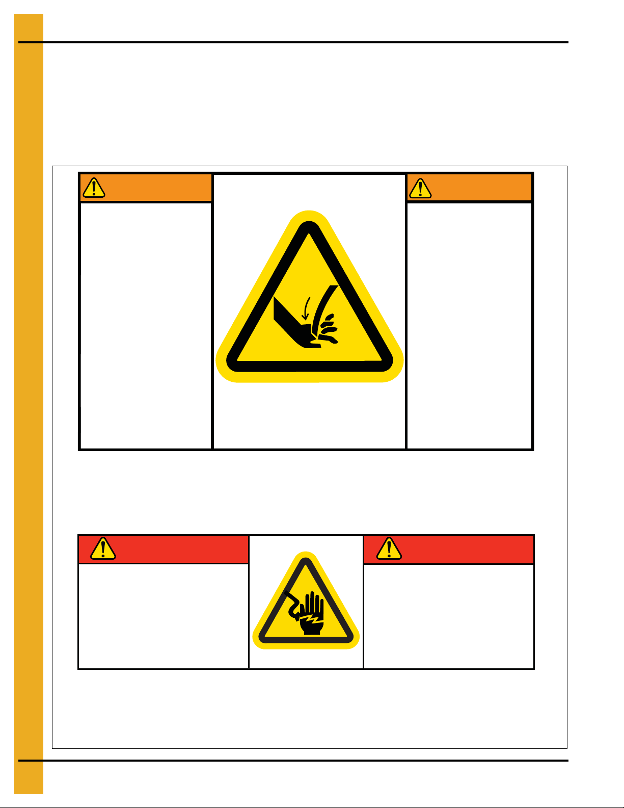
Stay clear of rotating
blade. Blade could
start automatically.
Can cause serious
injury. Disconnect
power before
servicing.
Restez éloigné de la
lame tournante. La
lame peut se mettre
en marche
automatiquement.
Peut causer de
sérieuses blessures.
Vérouillez le courant
avant l’entretien.
WARNING
AVERTISSEMENT
DC-1949GSI Group Inc. 217-226-4421
Part #: DC-1949
Size: 4-7/8" x 3"
Located on fan housing side near fan inlet.
Part #: DC-1948
Size: 4-3/8" x 1-3/8"
Located inside control box.
DANGER
DANGER
Safety decals should be read and understood by all people in the grain handling area. If a decal is
damaged or is missing contact:
GSI Decals
1004 E. Illinois St.
Assumption, IL. 62510
Phone: 1-217-226-4421
A free replacement will be sent to you.
DANGER
HIGH VOLTAGE
Will cause serious
injury or death.
Lockout power
before servicing.
GSI Group 217-226-4421
10 PNEG-163-08 Centrifugal Fan
DANGER
HAUTE TENSION
Causera de sérieuses
blessures ou la mort.
Couper/verrouiller le
courant avant l’entretien.
DC-1948
Page 11
2. Safety Decals
DC-994
DC-994
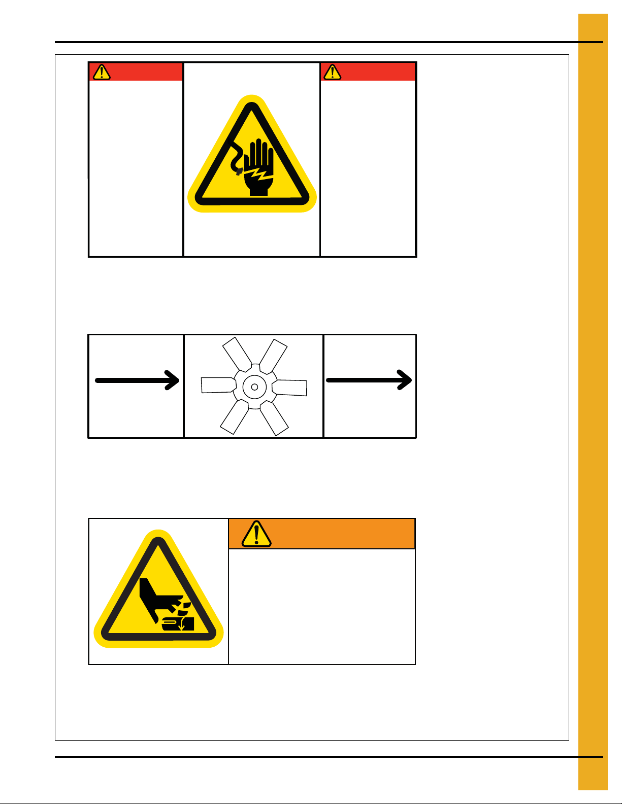
AIRFLOW
AIRFLOW
CIRCULATION D’AIR
CIRCULATION D’AIR
DC-1971
Part #: DC-1749
Size: 3-3/4" x 1-3/4"
Located on fan coupling guard on motor driven fans.
Part #: DC-1971
Size: 4-3/4" x 1-1/2"
Located on painted inlet cone of fan housing.
DANGER
DANGER
Part #: DC-1943
Size: 5" x 3"
Located on fan housing side above motor and located on
outside of control box lid.
DANGER
HIGH VOLTAGE.
Will cause injury
or death.
Lockout power
before servicing.
GSI Group 217-226-4421
DANGER
HAUTE TENSION.
Causera des
blessures ou la
mort.
Bloquez le courant
avant de faire
l’entretien.
DC-1943
WARNING
ROTATING SHAFT.
Do not operate with
ã1994HC S,Inc.
GSI Group 217-226-4421
PNEG-163-08 Centrifugal Fan 11
guard removed.
Lockout/tagout
before servicing.
DC-1749
Page 12
2. Safety Decals
DC-994
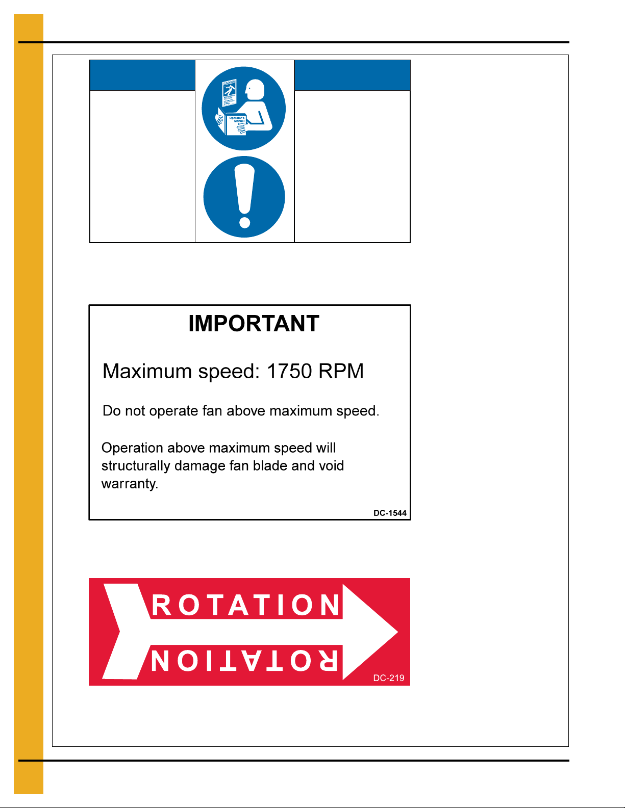
NOTICENOTICE
GSI Group 217-226-4421 DC-2111
Read owner’s manual
before operating.
To maintain proper
working components
and avoid possible
failure at harvest time,
operate motor unit for
20 minutes each month.
AVISAVIS
LIRE LE MANUEL DU
PROPRIÉTAIRE AVANT
DE FAIRE FONCTIONNER.
FAIRE FONCTIONNER
ĽUNITÉ DE MOTEUR
MENSUELLEMENT ET
CE PENDANT 20 MINUTES.
CECI PERMET DE MAINTENIR
UN BON FONCTIONNEMENT
DES COMPOSANTS ET
AUSSI D`ÉVITER UNE
POSSIBILITÉ DE DÉFAILLANCE
VENANT LE TEMPS DE LA
RÉCOLTE.
Part #: DC-21 11
Size: 3" x 5"
Located on fan housing motor side.
Part #: DC-219
Size: 3-1/2" x 1"
Located on fan inlet cone.
Part #: DC-1544
Size: 4" x 6"
Located on fan housing motor side.
12 PNEG-163-08 Centrifugal Fan
Page 13
2. Safety Decals
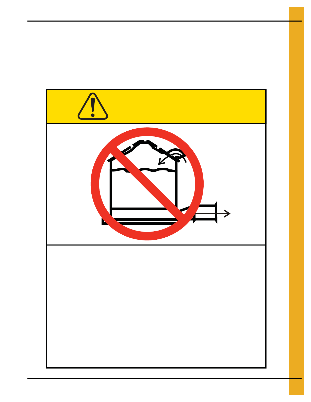
Roof Damage Warning and Disclaimer
The manufacturer does not warrant any roof damage caused by excessive vacuum or internal
pressure from fans or other air moving systems. Adequate ventilation and/or “makeup air” devices
should be provided for all powered air handling systems. The manufacturer does n ot recommend
the use of downward flow systems (suction). Severe roof damage can result fro m any blockage of
air passages. Running fans during high humidity/cold weather conditions can cause air exhaust
or intake ports to freeze.
CAUTION
Excessive vacuum (or pressure) may
damage roof. Use positive aeration
system. Make sure all roof vents are
open and unobstructed. Start roof
fans when supply fans are started.
Do not operate when conditions exist
that may cause roof vent icing.
GSI Group, Inc. 217-226-4421
PNEG-163-08 Centrifugal Fan 13
DC-969
Page 14

3. Installation
Pre-Installation Requirements
Foundation
Use the dimension illustration in the specifications section on Page 20 of this manual to determine the
physical size of the fan to be installed. Use the dimensions shown to determine the position of the fan
installation with respect to other equipment.
For proper operation of the fan, the unit is to be mounted on a level pad. The fan should not be anchored
to the pad, but it should be allowed to “float” on the pad. The fan pad should be offset 2" below the
top of the bin foundation. Refer to Figure 4F on Page 24 in the specifications section of this manual for
recommendations of pad placement with respect to various catalog transition ducts.
Transition
The transition duct should be all metal construction, with a gradual angle to the rectangular opening in the
bin wall. The duct should allow for a smooth transition with minimal resistance of the airflow from the fan
discharge to the bin plenum. Keep the entrance of the plenum as clear as possible from obstructions by
floor support.
Roof Exhaust
Adequate exhaust air openings in the roof are required to prevent any additional back pressure from
building in the bin. See roof damage warning on Page 13.
Power Supply
Adequate power must be supplied to the fan for reliable operation. Consult the local power company and
have a representative survey the installation. Only the power company can ensure that their system is
sized properly to provide adequate service to the installation and new equipment.
Wire Size
Undersized wire can lead to voltage drop which causes motor overheating and shortened motor life.
Use the electrical specifications chart on Page 18 in this manual to size the supply wire according to
the horsepower of the fan and the distance to the power supply. Refer to the fan specifications
on Page 18 to find the full load current of the motor for a given fan size. The full load current can also
be found on the motor nameplate.
Service Disconnect
Each fan motor must be supplied with an independent power circuit, equipped with a fused disconnect
switch. Locate this switch near the unit, as the power should be shut off before servicing the fan.
It is the customer’s responsibility to provide a fused disconnect and motor overload protection.
These must be properly sized and connected to allow proper motor operation. Failure to provide
these components could cause severe motor damage and void the manufacturer’s warranty.
14 PNEG-163-08 Centrifugal Fan
Page 15

3. Installation
DANGER
Always disconnect and lock out power before working on or around fan.
Fan Installation
1. Remove packaging materials and inspect fan for any shipping damages. Report these at once to
the shipper.
2. Check all fasteners on the fan to make sure they are tight. (Fasteners may loosen during shipment.)
Tighten any loose fasteners, check for proper clearance and retighten.
3. Check all electrical connections that may have loosened during shipment.
4. Rotate the fan wheel. Wheel should rotate freely and should not make contact with the housing sides
or inlet cone.
5. Place fan in proper location on the fan pad. Attach fan to transition duct and seal connection
with caulk.
6. Check all joints and seams around the lower part of the bin. Verify that these are well sealed to
prevent air leakage from the bin plenum. Inspect the transition duct as well. Seal any leaks that may
be present to prevent air losses that reduce fan efficiency.
7. Level fan. Fan pad should be poured flat and level, however, it may be necessary to adjust the legs
provided on the fan housing to level the fan. The legs should be adjusted so that when level, all
five (5) legs touch the pad. Fans not resting on support legs may have excess vibration which can
lead to premature wear and tear on fan components.
IMPORTANT: Electrical installation must be performed by a q ualified electrician, in accordance with
National and Local Electrical Codes. Any violation of electrical wiring codes could
jeopardize the warranty.
Electrical Installation
1. Verify that the incoming power supply has been deemed adequate by the local power company.
2. Verify that the wiring supplying power to the fan is sized correctly for the distance away from supply
and fan horsepower. (See tables in specification section on Page 18.)
3. Verify that the safety disconnect is installed and sized correctly for the fan size. (See tables in
specification section on Page 18.)
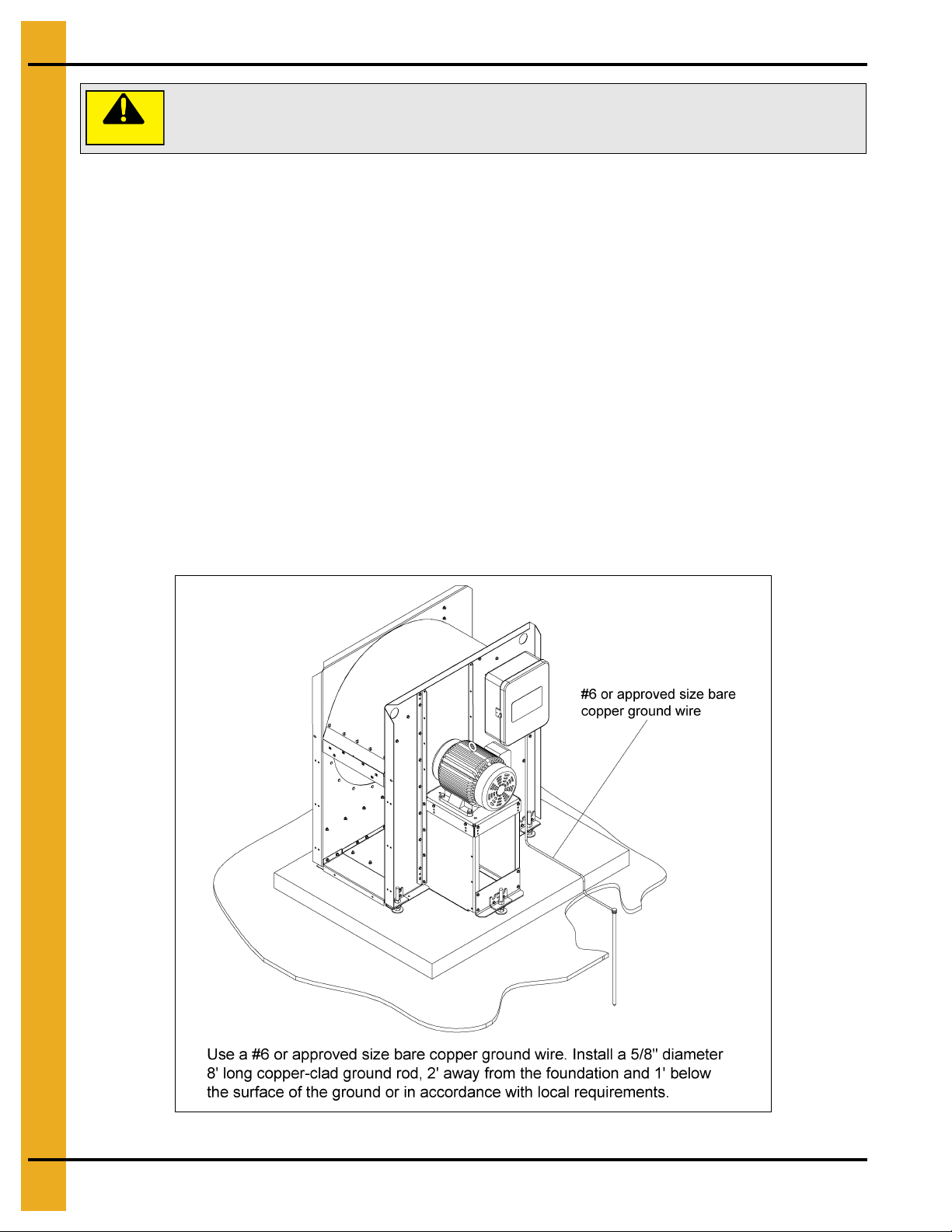
4. Install a machine to earth ground for each individual fan. Refer to the ground rod installation
on Page 17.
5. The following wires must be supplied to each fan. Units without control transformers require a
separate neutral and earth ground connection.
1 PH 230V L1, L2, N, G
3 PH 230V L1, L2, L3, N, G
3 PH 230V with Optional Transformer Kit L1, L2, L3, G
3 PH 460V/575V L1, L2, L3, G
6. The starter controls require 115 VAC power to operate. On 230 volt 3 phase units, this power is
supplied by L1 to neutral.
PNEG-163-08 Centrifugal Fan 15
Page 16
3. Installation
The voltage between L1 and N must be 115 VAC. Any other voltage will cause
damage to equipment.
CAUTION
Check this voltage before starting unit. If voltage is not within 105 VAC-125 VAC, check for proper
voltage on L2 or L3 and move to appropriate leg. If voltage is not acceptable, install a 1/4 KVA
step-down transformer.
NOTE: Grounded B and some open delta power supplies will require this transformer kit.
Final Check
Check to make sure all safety guards are in place and not damaged. Replace damaged parts.
Check to make sure all decals are visible and not damaged. Replace damaged decals.
Check to make sure all control boxes are closed and no wiring is exposed.
Test Run
When the fan is completely installed, the unit will need to be checked for proper rotation. Provide power
to the fan controls and start the fan momentarily. Make sure that the fa n wheel rotation is in the direction
that the decal on the fan housing illustrates. If the decal is missing, note that the wheel should operate
counterclockwise when viewed through the inlet guard on standard construction fans. If the wheel is
rotating the wrong direction, have the electrician correct the wiring.
Figure 3A
16 PNEG-163-08 Centrifugal Fan
Page 17
3. Installation
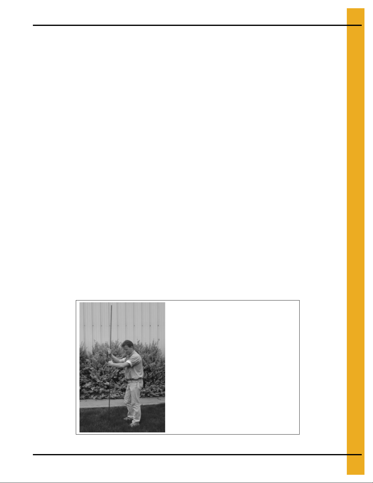
Dig a hole large enough to hold 1 or
2 gallons of water.
Work the ground rod into the earth
until it is completely in the ground.
Machine to Earth Ground
It is very important that a machine to earth ground rod be in stalled at the fan. This is true eve n if there is
a ground at the pole 15' away. This ground needs to be as close to the fan as possible, but no more than
8' away. The ground rod should be connected to the fan control panel with at least a #6 solid bare copper
ground wire, or in accordance with local requirements. The machine to earth ground provides additional
safety if there is a short. It also provides the gr ounding necessary for long life and operation of the solid
state circuit boards used on control circuits and the electronic ignition systems.
Previously Installed Units
It is recommended that previously installed units be checked to see tha t a machine to earth ground h as
been installed by an electrician.
Ground Rod Installation
Proper Installation of the Ground Rod
(Ground rods and wires are not supplied.) It is recommended that the rod not be driven into d ry ground.
The following steps ensure proper ground rod installation:
1. Dig a hole large enough to hold 1 to 2 gallons of water.
2. Fill hole with water.
3. Insert rod through water and jab it into the ground.
4. Continue jabbing the rod up and down, the water will work its way down the hole, making it
possible to work the rod completely into the ground. This method of installing the rod gives a
good conductive bond with the surrounding soil.
5. Connect the bare copper ground wire to the rod with the proper ground rod clamp.
6. Connect the bare ground wire to the fan control boxes with a grounding lug.
7. Ground wire must not have any breaks or splices. Insulated wire is not recommended for grounding .
PNEG-163-08 Centrifugal Fan 17
Figure 3B
Page 18
4. Fan Specifications
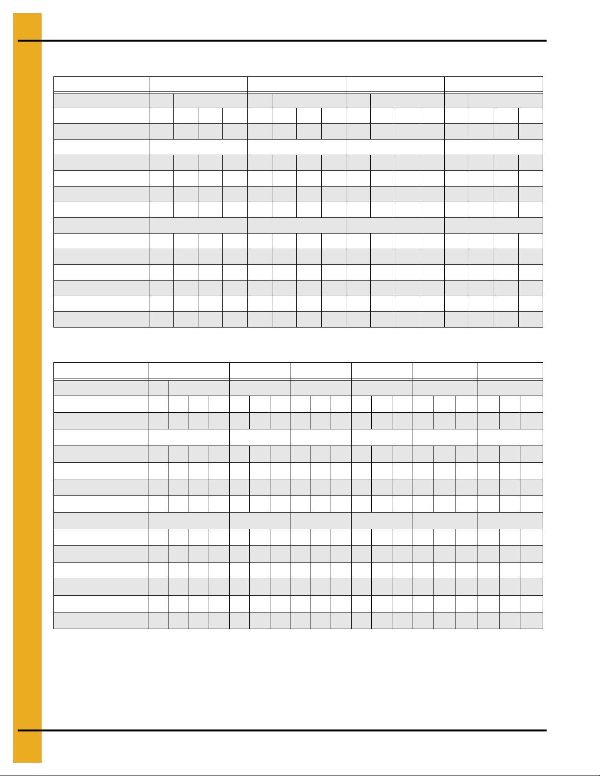
1750 RPM Fan Electrical Specifications
Fan Horsepower 3 5 7-1/2 10
Phase 1 3 1 3 1 3 1 3
Volts 230 230 460 575 230 230 460 575 230 230 460 575 230 230 460 575
Full Load Current (Amps) * 17 9.6 4.8 3.9 28 15.2 7.6 6.1 40 22 11 9 50 28 14 11
Minimum Wire Size Copper Wire Copper Wire Copper Wire Copper Wire
50' Run 12 14 14 14 10 14 14 14 8 10 14 14 6 10 14 14
100' Run 12141414 8 121414 8 101414 6 101414
200' Run 8 12 14 14 6 10 14 14 4 8 14 14 4 6 12 14
300' Run 6 10 14 14 4 8 14 14 3 6 12 14 2 4 10 12
Minimum Wire Size Aluminum Wire Aluminum Wire Aluminum Wire Aluminum Wire
50' Run 10121212 8 121212 6 101212 4 8 1212
100' Run 8 12 12 12 6 10 12 12 6 8 12 12 4 8 12 12
200' Run 6 10 12 12 4 8 12 12 3 6 12 12 2 4 10 12
300' Run 4 8 12 12 3 6 12 12 1 4 10 12 0 3 8 10
Fuse Size (Slow Blow) 3015 8 6 502512107040201590452520
Breaker Size 50 15 15 15 70 30 15 15 100 40 20 15 125 50 30 20
* Based on NEC Tables 430-148 and 430-150
Fan Horsepower 15 20 25 30 40 50
Phase 1 3 3 3 3 3 3
Volts 230 230 460 575 230 460 575 230 460 575 230 460 575 230 460 575 230 460 575
Full Load Current (Amps) * 65 42 21 17 54 27 22 68 34 27 80 40 32 104 52 41 130 65 52
Minimum Wire Size Copper Wire Copper Wire Copper Wire Copper Wire Copper Wire Copper Wire
50' Run 4 6 10 12 4 10 10 4 8 10 3 8 8 1 6 6 00 4 6
100' Run 4 6 10 12 4 10 10 4 8 10 3 8 8 1 6 6 00 4 6
200' Run 3 4 10 12 4 10 10 3 8 10 3 8 8 1 6 6 00 4 6
300' Run 1 4 10 10 3 8 10 2 6 81680 6 6004 6
Minimum Wire Size Aluminum Wire Aluminum Wire Aluminum Wire Aluminum Wire Aluminum Wire Aluminum Wire
50' Run 241010381026816800440000 2 4
100' Run 2 4 10 10 3 8 10 2 6 8 1 6 8 00 4 4 0000 2 4
200' Run 1 3 8 10 2 8 10 1 6 806800440000 2 4
300' Run 00 1 6 8 0 6 8 00 4 6 00 4 6 000 4 4 0000 2 4
Fuse Size (Slow Blow) 125 70 40 30 90 45 40 110 60 45 125 60 50 175 80 70 200 100 80
Breaker Size 175 70 40 30 90 50 40 110 60 50 125 60 50 175 80 70 200 100 80
* Based on NEC Tables 430-148 and 430-150
IMPORTANT: The values listed in this chart are recommendations only. Electrical installation must
be performed by a qualified electrician, in accordance with National and Local Electrical
Codes. Any violation of electrical wiring codes could jeopardize the warranty.
18 PNEG-163-08 Centrifugal Fan
Page 19

4. Fan Specifications
3500 RPM Fan Electrical Specifications
Fan Horsepower 3 5 7-1/2 10
Phase 1 3 1 3 1 3 1 3
Volts 230 230 460 575 230 230 460 575 230 230 460 575 230 230 460 575
Full Load Current (Amps) * 17 9.6 4.8 3.9 28 15.2 7.6 6.1 40 22 11 9 50 28 14 11
Minimum Wire Size Copper Wire Copper Wire Copper Wire Copper Wire
50' Run 12 14 14 14 10 14 14 14 8 10 14 14 6 10 14 14
100' Run 12 14 14 14 8 12 14 14 8 10 14 14 6 10 14 14
200' Run 8 12 14 14 6 10 14 14 4 8 14 14 4 6 12 14
300' Run 6 10 14 14 4 8 14 14 3 6 12 14 2 4 10 12
Minimum Wire Size Aluminum Wire Aluminum Wire Aluminum Wire Aluminum Wire
50' Run 10 12 12 12 8 12 12 12 6 10 12 12 4 8 12 12
100' Run 8 12 12 12 6 10 12 12 6 8 12 12 4 8 12 12
200' Run 6 10 12 12 4 8 12 12 3 6 12 12 2 4 10 12
300' Run 4 8 12 12 3 6 12 12 1 4 10 12 0 3 8 10
Fuse Size (Slow Blow) 30158 6 50 2512107040201590452520
Breaker Size 50 15 15 15 70 30 15 15 100 40 20 15 125 50 30 20
* Based on NEC Tables 430-148 and 430-150
Fan Horsepower 15 20 30 40 50
Phase 3 3 3 3 3
Volts 230 460 575 230 460 575 230 460 575 230 460 575 230 460 575
Full Load Current (Amps) * 42 21 17 54 27 22 80 40 32 104 52 41 130 65 52
Minimum Wire Size Copper Wire Copper Wire Copper Wire Copper Wire Copper Wire
50' Run 6 10 12 4 10 10 3 8 8 1 6 6 00 4 6
100' Run 6 10 12 4 10 10 3 8 8 1 6 6 00 4 6
200' Run 4 10 12 4 10 10 3 8 8 1 6 6 00 4 6
300' Run 4 10 10 3 8 10 1 6 8 0 6 6 00 4 6
Minimum Wire Size Aluminum Wire Aluminum Wire Aluminum Wire Aluminum Wire Aluminum Wire
50' Run 4 10 10 3 8 10 1 6 8 00 4 4 0000 2 4
100' Run 4 10 10 3 8 10 1 6 8 00 4 4 0000 2 4
200' Run 3 8 10 2 8 10 0 6 8 00 4 4 0000 2 4
300' Run 1 6 8 0 6 8 00 4 6 000 4 4 0000 2 4
Fuse Size (Slow Blow) 70 40 30 90 45 40 125 60 50 175 80 70 200 100 80
Breaker Size 70 40 30 90 50 40 125 60 50 175 80 70 200 100 80
* Based on NEC Tables 430-148 and 430-150
IMPORTANT: The values listed in this chart are recommendations only. Electrical installation must be
performed by a qualified electrician, in accordance with National and Local Electrical
Codes. Any violation of electrical wiring codes could jeopardize the warranty.
PNEG-163-08 Centrifugal Fan 19
Page 20
4. Fan Specifications
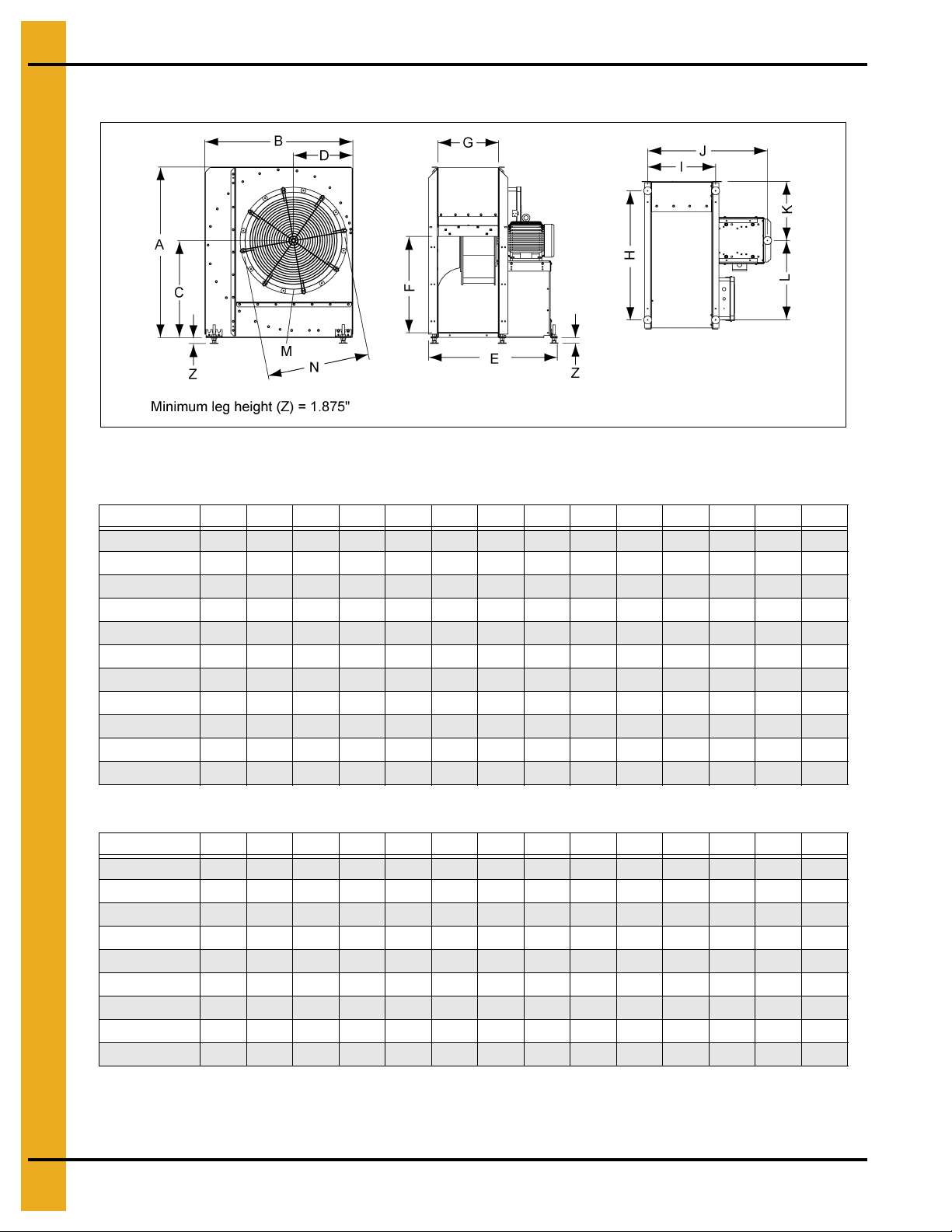
Fan Dimensions
Figure 4A
1750 RPM Fan Housing Dimensions
Fan ABCDEFGH I JKLMN
CF-3 44 37.875 25.094 15.313 30.813 23.593 13.5 32.094 15.688 28.813 15.313 19.656 24.875 26.125
CF-5 48.563 42 27.719 17.063 34.688 27.25 14.25 36.125 16.438 32.563 17.063 21.968 27.375 29.125
CF-7.5 48.563 42 27.719 17.063 38.438 27.25 18 36.125 20.188 36.313 17.063 21.968 27.375 29.125
CF-10 53 45.938 30.125 18.406 38.625 29.875 17.438 40.094 19.781 35.844 18.406 24.656 30 31.75
CF-15 53 45.938 30.125 18.406 40.063 29.875 18.875 40.094 21.219 37.281 18.406 24.656 30 31.75
CF-20 58.906 50.563 33.34 20.094 45.438 33.25 19.563 44.438 21.813 42.906 20.094 27.281 33.625 35.125
CF-25 58.906 50.563 33.34 20.094 47.75 33.25 21.875 44.438 24.063 45.125 20.094 27.281 33.625 35.125
CF-30 64.406 55.75 36.219 22.25 47.688 33.25 21.875 49.844 24.125 45.25 22.313 30.532 36.5 38.375
CF-40 64.406 55.75 36.219 22.25 49.5 33.25 23.688 49.844 25.938 47.063 22.313 30.532 36.5 38.375
CF-50 64.406 55.75 36.219 22.25 50.625 33.25 25.25 49.844 27.5 48.625 22.313 30.532 36.5 38.375
CF-30D - CF-50D 56.498 51.756 32.938 22.688 90.625 33.25 44 42.5 46.532 89.563 22.688 25.089 33.5 35.125
3500 RPM Fan Housing Dimensions
Fan ABCDEFGH I JKLMN
CHS-3 30.031 29.813 17.375 12.813 27.188 16.5 8.125 24.156 10.281 25.375 12.813 14.156 16.5 17.875
CHS-5 30.031 29.813 17.375 12.813 28.969 16.5 10 24.156 12.156 27.25 12.813 14.156 16.5 17.875
CHS-7.5 36.375 33.375 20.875 13.281 29.938 19 10 27.688 12.219 28.219 13.281 17.219 20.5 21.75
CHS-10 36.375 33.375 20.875 13.281 30.938 19 11 27.688 13.219 29.219 13.281 17.219 20.5 21.75
CHS-15 36.375 33.375 20.875 13.281 32.938 19 13 27.688 15.219 31.219 13.281 17.219 20.5 21.75
CHS-20 44 37.875 25.094 15.313 37.813 23.563 12.563 32.094 14.75 35.813 15.313 19.656 24.875 26.125
CHS-30 44 37.875 25.094 15.313 39.313 23.563 14.063 32.094 16.25 37.313 15.313 19.656 24.875 26.125
CHS-40 44 37.875 25.094 15.313 41.75 23.563 16.5 32.094 18.688 39.75 15.313 19.656 24.875 26.125
CHS-50 48.563 42 27.719 17.063 41.125 27.25 15.75 36.125 17.938 39 17.063 21.968 27.375 29.125
NOTE: All dimensions in inches to nearest 1/32".
NOTE: Add 8.125" to ‘A’ dimension for 3500 RPM fans with control boxes.
20 PNEG-163-08 Centrifugal Fan
Page 21

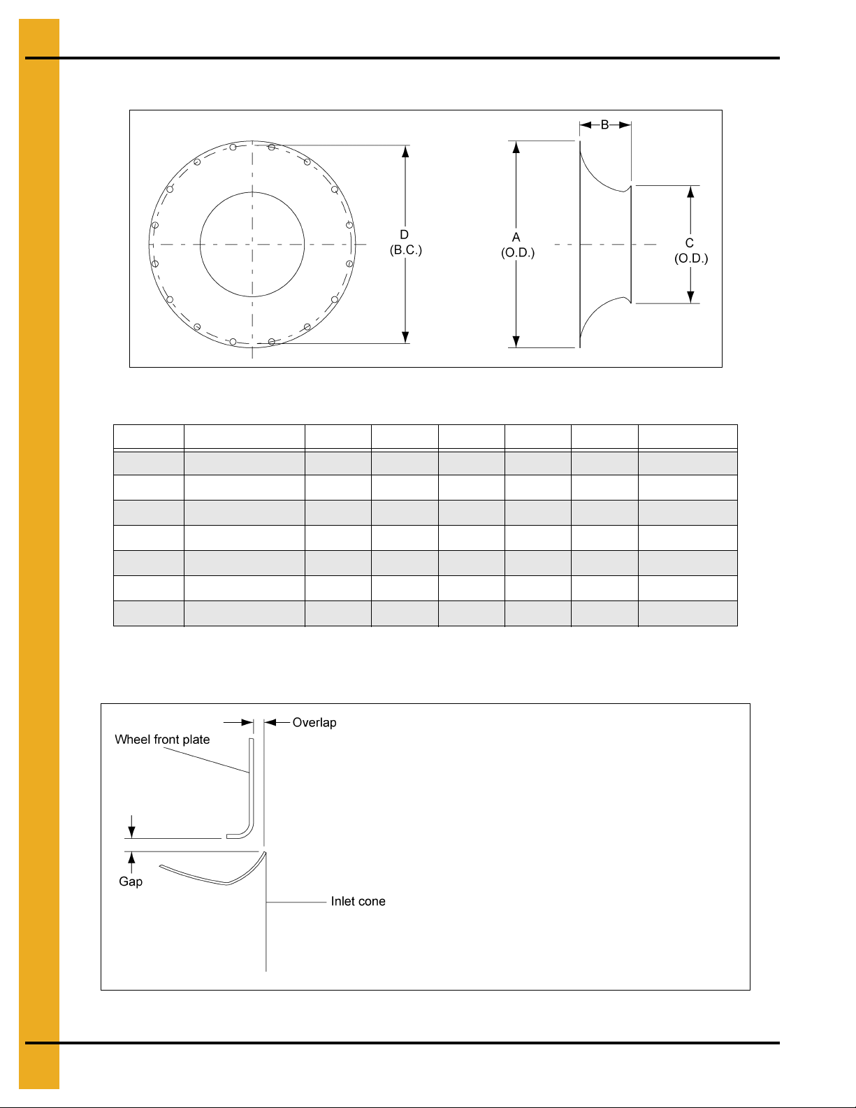
Discharge Bolt Pattern Dimensions
Figure 4B
4. Fan Specifications
1750 RPM Discharge Dimensions
Fan A B C D E F G H I J
CF-3 1.531 4.688 5.906 5.906 7.094 1.094 0.875 2.406 7.844 ***
CF-5 1.813 5.125 8.438 8.438 5.218 0.875 0.75 2.75 8.031 ***
CF-7.5 1.813 5.125 8.438 8.438 5.218 0.875 0.75 3.75 9.906 ***
CF-10 1.594 3.5 11.5 11.5 3.344 0.813 0.688 3.75 9.594 10.563
CF-15 1.594 3.5 11.5 11.5 3.344 0.813 0.688 5.75 10.313 11.281
CF-20 1.656 8.156 8.469 8.469 8.188 0.75 0.75 5.75 10.5 11.656
CF-25 1.656 8.156 8.469 8.469 8.188 0.75 0.75 5.75 11.656 12.813
CF-30 1.281 8.188 8.438 8.438 8.156 0.75 0.75 5.75 11.656 ***
CF-40 1.281 8.188 8.438 8.438 8.156 0.75 0.75 5.75 12.563 ***
CF-50 1.281 8.188 8.438 8.438 8.156 0.75 0.75 5.75 13.344 ***
CF-30D - CF-50D 1.313 8.031 8.438 8.438 8.219 0.656 0.813 3.0 * 22.906 ***
* 4 Holes @ 6" Spacing
3500 RPM Discharge Dimensions
Fan A B C D E F G H I J
CHS-3 1.625 4.313 4.125 4.125 4.063 1 0.781 2 5.125 ***
CHS-5 1.625 4.313 4.125 4.125 4.063 1 0.781 2 6.094 ***
CHS-7.5 1.625 3.531 4.75 4.75 6 1.094 0.875 2 6.094 ***
CHS-10 1.625 3.531 4.75 4.75 6 1.094 0.875 2 6.094 ***
CHS-15 1.625 3.531 4.75 4.75 6 1.094 0.875 2 6.094 ***
CHS-20 1.531 4.688 5.906 5.906 7.094 1.094 0.875 2.406 7.375 ***
CHS-30 1.531 4.688 5.906 5.906 7.094 1.094 0.875 2.781 8.125 ***
CHS-40 1.531 4.688 5.906 5.906 7.094 1.094 0.875 3.063 9.344 ***
CHS-50 1.813 5.125 8.438 8.438 5.219 0.875 0.75 3.063 8.781 ***
NOTE: All dimensions in inches to nearest 1/32".
PNEG-163-08 Centrifugal Fan 21
Page 22
4. Fan Specifications
Gap
The “Gap” between the cone and wheel should be equal
distance all around the cone’s inner edge.
Overlap
The “Overlap” of the wheel over the cone should be a
minimum distance to allow free rotation without interference.
Inlet Cone Dimensions
SizePainted Part #ABCDHole Size# of Holes
Figure 4C
15 C-7743 18.625 4.000 10.375 9.875 0.688 8
18 C-7745 22.750 5.388 12.625 21.750 0.875 16
22 C-7747 27.125 6.750 15.625 26.125 0.875 16
24 C-7749 30.500 7.250 17.000 29.125 1.000 16
27 C-7751 33.125 8.000 18.813 31.750 1.000 16
30 C-7753 36.500 9.000 21.125 35.125 1.000 16
33 C-7754 38.750 10.000 23.063 38.376 1.000 16
Add suffix to painted part # for correct color. “-Y” = YELLOW, “-R” = RED, “-O” = ORANGE
Inlet Cone to Wheel Clearances
Figure 4D
22 PNEG-163-08 Centrifugal Fan
Page 23
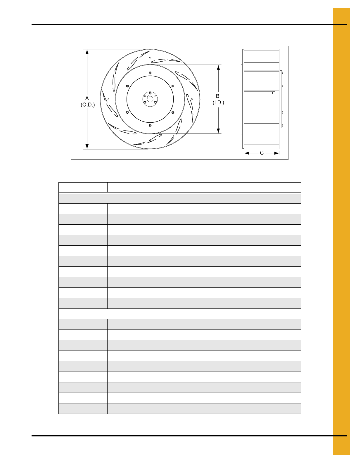
Fan Wheel Dimensions
4. Fan Specifications
Figure 4E
Fan Model Wheel Assembly Part # * Size A B C
1750 RPM Fans
CF-3 CH-6878 22 23.000 15.875 4.956
CF-5 C-956 24 25.250 17.188 5.938
CF-7.5 C-957 24 25.250 17.188 8.875
CF-10 C-8533 27 27.625 19.000 8.375
CF-15 C-960 27 27.625 19.000 9.750
CF-20 CH-2076 30 30.625 21.313 9.625
CF-25 C-2046 30 30.625 21.313 10.750
CF-30 C-7319 33 33.156 23.428 9.000
CF-40 C-7320 33 33.156 23.428 11.625
CF-50 C-8517 33 33.156 23.428 13.500
3500 RPM Fans
CHS-3 FH-5464 15 15.500 10.625 2.875
CHS-5 FH-5465 15 15.500 10.625 4.750
CHS-7.5 FH-5466 18 18.750 12.750 3.000
CHS-10 FH-5467 18 18.750 12.750 4.000
CHS-15 FH-5468 18 18.750 12.750 6.000
CHS-20 FH-5469 22 23.000 15.875 3.938
CHS-30 FH-5470 22 23.000 15.875 5.938
CHS-40 FH-5758 22 23.000 15.875 7.875
CHS-50 FH-5852 24 25.250 17.188 6.938
* Wheel Assembly is Blade and Bushing
PNEG-163-08 Centrifugal Fan 23
Page 24
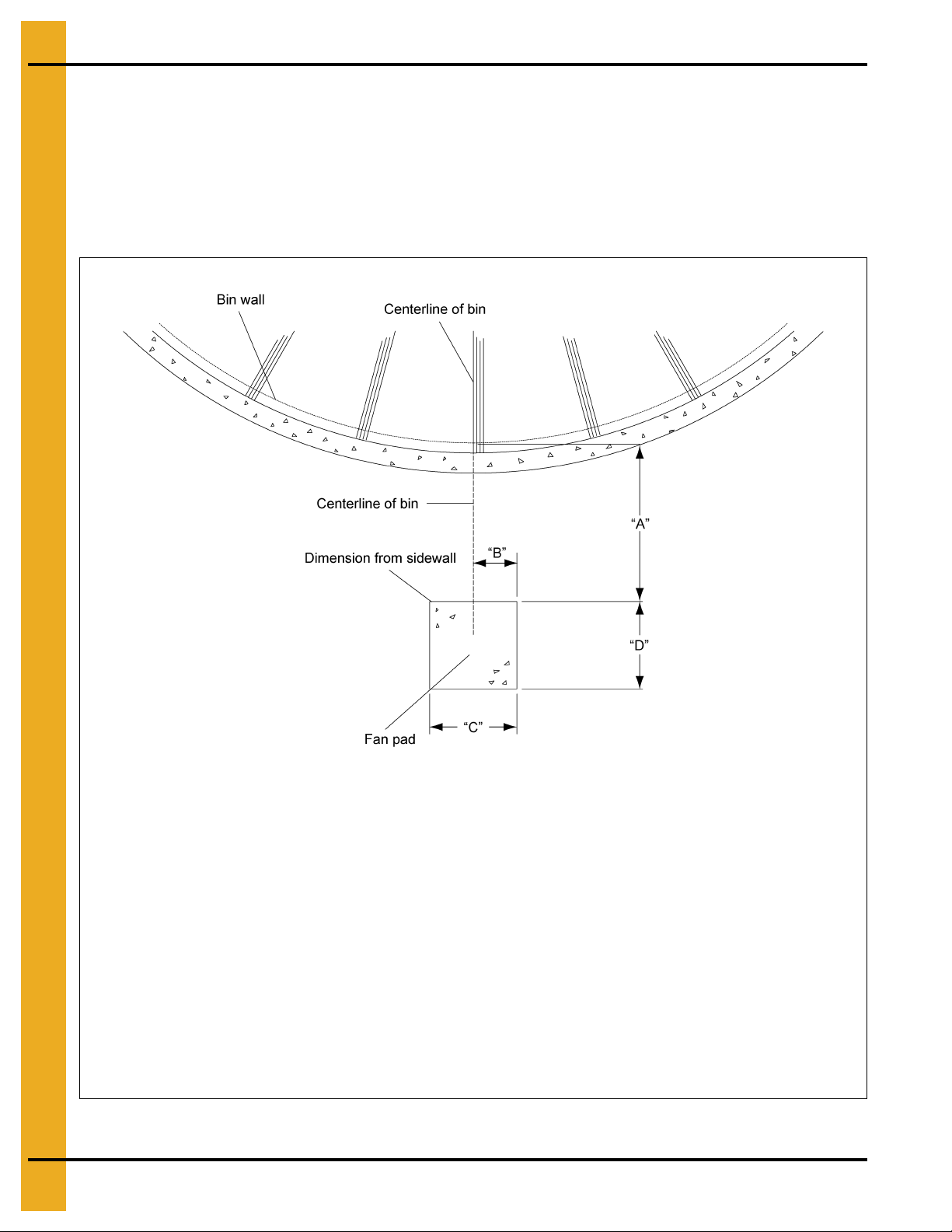
4. Fan Specifications
Front of pad should be perpendicular to bin wall. Recommended thickness for fan pad is
4" minimum. Surface of pad should be 2" below the bin foundation. Pad for heater not required.
TR-4734
A = 20" without heater
A = 44" with heater
B = 10"
C = 40"
D = 40"
TR-7048
A = 45" without heater
A = 69" with heater
B = 10"
C = 40"
D = 48"
TR-6918 and
TR-6919
A = 32" without heater
A = 65" with heater
B = 13"
C = 48"
D = 52"
TR-7049
A = 45" without heater
A = 78" with heater
B = 13"
C = 48"
D = 52"
TR-6207
A = 42" without heater
A = 78" with heater
B = 13"
C = 48"
D = 60"
TR-6958
A = 55" without heater
A = 85" with heater
B = 13"
C = 48"
D = 60"
TR-6853 (Double inlet)
A = 54" without heater
A = 88" with heater
B = 28"
C = 100"
D = 60"
TR-4013
A = 36" without heater
B = 13"
C = 48"
D = 60"
TR-6944
A = 48" without heater
B = 13"
C = 48"
D = 60"
Fan Pad Location
Fan pad should be perpendicular to bin wall. Fan discharge centerline should lie on bin centerline.
Recommended thickness for pad is 4" minimum. Top surface of pad should be 2" below bin
foundation. Fans with downwind heaters require fan pad to be 48" wide and add 33" onto length (D).
IMPORTANT: Fan pad and fan must be level and smooth for proper operation. Vibration problems can
result from improper fan leveling.
24 PNEG-163-08 Centrifugal Fan
Figure 4F
Page 25

5. Operation
WARNING
Make certain all guards and covers are securely in place.
After initial installation and also prior to using the unit each season, check the operation to ensure proper
functioning, adjustment and reliability.
Fan Start-Up
1. Make certain the unit is properly installed and connected, as described within the installation section
on Page 14 of this manual. All air passage joints and seams must be well sealed.
2. With main power supply turned OFF, rotate the wheel by hand to make certain it turns freely without
contacting the housing or inlet cone.
3. Open roof doors to allow airflow at all times when fan is operating.
NOTE: Refer to roof damage disclaimer in the safety section on Page 13 of this manual.
4. Turn ON main power disconnect switch.
5. Press the fan START button and check the following:
a. Check direction of wheel rotation. Correct if needed by following the instructions on the motor.
b. Check to make sure the wheel comes to full operating speed in less than 10 seconds. If there is
any doubt as to proper operation, check the current draw of the motor. The motor amperage
should not exceed the maximum full load amps listed on the motor nameplate.
Fan Shut Down
1. Press the fan STOP button on units equipped with motor controls.
2. Shut off electrical power at main and at disconnect.
3. Close the roof openings and cover fan inlet to prevent harmful back-draft air currents from passing
through the grain and to avoid grain infestation from rodents and insects.
Maintaining Grain Quality
To properly maintain the quality of stored grain, it is necessary to keep the grain dry, cool and insect free.
Any one of these problems can contribute to spoilage. Wet, warm grain promotes insect growth as well as
grain spoilage. Cool, dry grain can keep for long periods of time.
It is recommended that the grain be kept cool (avoid freezing as freezing can reduce quality). Grain should
be cooled through the fall and winter, warmed in the spring and summer.
IMPORTANT: Conditions and requirements may vary from area to area. Contact the local agriculture
extension office or State Agricultural University for more exact guidelines.
PNEG-163-08 Centrifugal Fan 25
Page 26

5. Operation
Grain Storage
Average grain temperature should be above 35°F in the winter and below 65°F in the summer. Always try
to keep the grain within 10°F-15°F of the average monthly outside temperature. This means grain may
need to be aerated on warm days during the winter to stay above 35°F when freezing temperatures are
predominate. During the summer it may be necessary to aerate the grain on cool nights, so the 65°F
temperature is not exceeded during the hot days of summer.
If the grain is to be stored more than 1 year, it has to be recooled the following fall and winter, repeating
the process as long as the grain is in storage. Frequent and regular inspection (at least weekly during
fall and spring) is the best prevention against grain spoilage.
26 PNEG-163-08 Centrifugal Fan
Page 27

6. User Servicing Instructions and Troubleshooting
DANGER
Always disconnect and lock out power before working on or around fan.
CAUTION
Although the taper-lock method of retaining the wheel onto the motor shaft is
very simple and obvious, it is essential that the following points be read
carefully and fully understood, as improper installation can result in serious or
fatal injury caused by a loose, fast flying wheel.
THREADED BUSHING HOLES:
The threaded holes within the bushing are
provided for disassembly purposes only. Do not attempt to use these holes for
reassembly, as they will not allow the parts to become locked onto the shaft,
thereby causing an extremely hazardous operating condition.
CLEARANCE HOLES:
When reassembling parts, the cap screws must be
installed through the UNTAPPED CLEARANCE HOLES to cause the wheel to
be pulled forward onto the tapered bushing, thus locking the parts securely
onto the motor shaft. Refer to Step 4 on Page 28 (under Installation section)
for assembly details.
Important Information Regarding Fuse Replacement
This product employs overload protection (fuse). A blown fuse indicates an overload or short circuit
situation. If the fuse blows, disconnect all power to the product. Replace the fuse as per the user servicing
instructions (follow product marking for proper fuse rating) and check the product. If the replacement fuse
blows, a short circuit may be present and the user should discontinue use of the product until customer
service can be contacted for further assistance.
Fan Wheel Removal and Installation
The fan wheel is secured to the motor shaft by the use of a taper-lock bushing, motor shaft key and cap
screws. The size, quantity and torque of cap screws required will depend on the model of the fan.
Removal
1. LOCK OUT THE MAIN POWER SUPPLY and remove the fan guard and inlet cone.
2. Remove the three (3) cap screws from the clearance holes in taper-lock bushing. Inspect for thread
damage and set aside for later reinstallation. (Do not use these bolts for Step 3, bushing removal.)
3. Install two (2) grade 5 (or better) cap screws into the THREADED HOLES in the bushing and turn
them in by hand until they bottom against the front surface of the wheel. These cap screws should
not be used for reassembly, as some thread distortion could occur during the removal operation.
Grade 5 screws are marked with three (3) 120° spokes on the head and are more du rable than low
strength unmarked bolts.
NOTE: Do not attempt to use low strength (unmarked) bolts to remove the bushing, as the bolts may
4. Block wheel to prevent it from turning and GRADUALLY TURN IN THE CAP SCREWS (up to 1/4
turn at time), until the wheel breaks loose from the bushing and motor shaft. Carefully remove
bushing and wheel. (With the wheel free from the bushing, a wheel puller can be used to pull the
bushing off of motor shaft, if required.) Reattach bushing onto wheel to prevent the loss of parts and
also to maintain the original alignment of bushing to wheel. Inspect wheel and bushing at this time,
looking for any cracks, thread or bolt damage, warpage, etc. Consult the dealer or the fa ctory for any
questions concerning damage.
PNEG-163-08 Centrifugal Fan 27
break off.
Page 28

6. User Servicing Instructions and Troubleshooting
Do not attempt to pull the flange of the bushing flush with the wheel hub.
A clearance of 1/8" to 1/4" must be maintained between bushing flange and
wheel hub surface. Wheel will loosen and cause damage or injury.
Installation
1. Carefully clean motor shaft, key, bushing and bore of wheel. MAKE SURE MAIN POWER IS
LOCKED OUT and that shaft and key are completely free of rust and burrs. DO NOT lubricate
the bushing or cap screws. CHECK AND MAKE SURE ALL MOTOR MOUNT BOLTS ARE
PROPERLY TIGHTENED. Before installing the wheel, check the following:
a. All foreign material should be removed from the wheel.
b. Carefully inspect the wheel weldment and hub casting for damage, cracks, or other defects.
Contact the factory if there is any question regarding the structural integrity of the wheel.
2. Slide wheel over motor shaft and locate it as far onto the motor shaft as possible.
3. Align the keyway in the bushing with the key and SLIDE bushing onto motor shaft. Do not attempt to
drive the bushing onto the shaft, as it may damage the motor bearings.
4. Rotate the bushing and wheel so their key slots are in line and loosely attach the wheel to the
bushing. MAKE SURE THE CAP SCREWS ARE INSERTED INTO THE UNTHREADED
CLEARANCE HOLES IN THE BUSHING. Refer to previous CAUTION note on Page 27. Locate the
bushing so it is approximately flush with the end of motor shaft. Make certain that the proper cap
screws are used for reassembly and no damage has occurred to these screws during disassembly.
Use only the special type bolts supplied with the original wheel.
5. Install inlet cone, checking clearance between fan wheel and inlet cone. Shift the location of inlet
cone as required to center it in relation to the fan wheel, providing equal clearance completely around
the fan wheel. Tighten inlet cone bolts.
6. Slide the wheel forward onto the taper-lock bushing and turn the cap screws in by hand as far
as possible.
NOTE: Th e bushing must be located far enough forward so the whee l weldment does not strike cone
as it rotates. Blade will move toward cone as it is tightened.
7. Use an INCH-POUNDS torque wrench and GRADUALLY TIGHTEN the three (3) cap screws
(1/4 turn at a time) until the taper bushing becomes fully seated. Refer to the chart on Page 29
for recommended cap screw tightening torques. DO NOT EXCESSIVELY OVERTIGHTEN
THE BUSHING.
8. Turn wheel by hand and check it for freedom of rotation and uniform clearance around inlet cone
before reinstalling the fan guard.
Fan Wheel Inspection and Maintenance
Pre-season inspections should be done on the fan wheel to look for the following.
1. Any debris (stalks, bees wings, mud, insects and insect nests) accumulated on the surfaces of
the fan wheel. Remove these items as they will likely disrupt airflow over the fan airfoils and can
potentially cause vibration problems.
2. Inspect the fan wheel for any broken, cracked, or loose parts. Blade should NOT be operated with
broken or loose parts. Contact dealer for determination of the repairs required.
WARNING
28 PNEG-163-08 Centrifugal Fan
Page 29

6. User Servicing Instructions and Troubleshooting
DANGER
Do not touch electrical connections before you first ensure that power has been
disconnected. Electrical shock can cause serious or fatal injury. Only qualified
personnel should attempt the installation, operation and maintenance of
this equipment.
Taper-Lock Bushing Torque Requirements
Browning Taper-Lock Bushing Bolt Tightening Torque
Bushing Size Hex Bolt Size Torque (inch-lbs)
P 5/16"-18 x 1-1/4" 192
Q 3/8"-16 x 1-1/2" 348
Fan Motor Removal and Installation
In the event of motor failure, remove the motor, as described and take it to the n earest authorized service
station. AUTHORIZED SERVICE STATIONS ARE THE ONLY PLACES THAT CAN PROVIDE MOTOR
WARRANTY. Motor service and repair at other places will be at owner’s expense. If service station
determines motor failure to be caused by faulty material or workmanship, repair will be under warranty
when within the warranty period. Motor failure because of external causes will result in a charge to the
owner for repair.
1. LOCK OUT THE MAIN POWER SUPPLY, then remove fan guard, inlet cone and wheel as
outlined earlier.
2. Open motor junction box cover and disconnect the motor lead wires from within the box.
NOTE: Tag, or otherwise identify wires for ease of reassembly.
3. Remove motor mount bolts. If there are any shims between the motor and its base, note their
locations so they can be properly installed during reassembly.
4. Disconnect the motor end of the motor conduit, if required, then carefully pull conduit and wires
through hole in the motor junction box. Remove motor. If motor requires service, take it to an
authorized service station.
5. To reinstall motor, slide onto motor base plate and replace shims (if required) between motor and
base plate. Reinstall motor mount bolts and washers and fully tighten them at this time. Reinstall
conduit and wires and carefully remake all electrical wiring connections.
NOTE: Make sure to install and tighten the wheel in accordance with earlier instructions.
General Inspection
Inspect the motor at regular intervals, approximately every 500 hours of operation or every 3 months,
whichever occurs first. Keep the motor clean and the ventilation openings clear. The following steps
should be performed at each inspection:
1. Check that the motor is clean. Check that the interior and exterior of the motor is free of dirt,
oil, grease, water, etc. Oily vapor, paper pulp, textile lint, etc., can accumulate and block motor
ventilation. If the motor is not properly ventilated, over heating can occur and cause early
motor failure.
2. Check all electrical connectors to be sure that they are tight.
PNEG-163-08 Centrifugal Fan 29
Page 30

6. User Servicing Instructions and Troubleshooting
To avoid damage to motor bearings, grease must be free of dirt.
Lubrication and Bearings
Bearing grease will lose its lubricating ability over time, not suddenly. The lubricating ability of a grease
(over time) depends primarily on the type of grease, the size of the bearing, the speed at which the bearing
operates and the severity of the operating conditions. Good results can be obtained if the following
recommendations are used in the maintenance program. Type of grease: A high grade ball
or roller bearing grease should be used.
Recommended grease for standard service conditions:
Polyrex EM (Exxon Mobile)
Equivalent and compatible greases include:
Texaco Polystar
Rykon Premium #2
Pennzoil Pen 2 Lube
Chevron SRI.
Lubrication Procedure
Be sure that the grease you are adding to the motor is compatible with the grease already in the motor.
With Grease Outlet Plug
1. Clean all grease fittings.
2. Remove grease outlet plug.
3. Add the recommended amount of grease.
4. Reinstall grease outlet plug.
Without Grease Outlet Plug
This requires disassembly of the motor. Contact local motor shop for assistance.
DANGER
Volume of Grease to Relubricate Bearings (Teaspoons)
NEMA Frame Size Qty
Up to 210 incl. 2
Over 210 to 280 incl. 3.9
Over 280 to 360 incl. 5.2
Over 360 to 449 incl. 13.4
30 PNEG-163-08 Centrifugal Fan
Page 31

6. User Servicing Instructions and Troubleshooting
Lubrication Intervals - Ball Bearing Motors
Type of Annual Usage 1800 RPM - NEMA Frame Size 3600 RPM - NEMA Frame Size
Up to
280 incl.
Continuous Normal Duty * 9500 Hrs 7400 Hrs 3500 Hrs 3600 Hrs 2200 Hrs 2200 Hrs
Continuous Severe Duty ** 4750 Hrs 3700 Hrs 1750 Hrs 1800 Hrs 1100 Hrs 1100 Hrs
Seasonal Service Motor (Idle 6 Months) Lube at the Beginning of Season and then follow the Appropriate Duty Interval above.
* Clean, Little Corrosion with 40°C maximum temperature.
** Moderate Dirt, Corrosion with 50°C maximum temperature. Average hours per month = 730
Over 280
to 360 incl.
Over 360
Up to
280 incl.
Over 280
to 360 incl.
Over 360
Troubleshooting Charts
Fan Troubleshooting Chart
Symptom Possible Cause Solution
To replace blown fuse, grasp center of fuse
securely and pull carefully outward to remove
Fan will not run.
Fan runs for a short
period of time then
shuts off.
Fan makes
ticking noise.
Fan vibrates.
Blown fuse or breaker in disconnect switch.
Main power not turned ON.
Defective wiring or loose connection.
Incorrect wire size.
Overload kicked out. Check manual reset, push in to reset.
Defective motor. Replace motor.
Defective magnetic contactor. Check the magnetic contactor.
Undersize wiring.
Low line voltage at the installation.
Power failure.
Magnetic contactor malfunctioning. Change magnetic contactor.
Defective start/stop button. Replace necessary part.
Overload setting incorrect. Adjust overload to proper setting.
Fan blade hitting housing.
Motor bearing bad. Replace motor bearing.
Fan not level. Level fan.
Fan has dirt deposits on blade. Clean blade.
Motor shaft is bent. Replace motor.
Blade not mounted properly on shaft. Mount blade properly on shaft.
Blade out of balance. Replace or have blade rebalanced.
fuse from fuse holder. RISK OF FIRE
. Replace
fuse only with equally rated fuse shown on
panel label.
Turn power ON at all disconnects ahead of
the unit.
Follow wiring diagram and tighten any
loose connections.
See wire size charts for proper wire size and
change if needed.
Check to see that power supply wires are the
proper size, contact the local power company.
Call power company after making sure wire size
is correct.
Stop fan and turn OFF power. Remove fan guard
and check to see if fan blade is hitting the
housing. Adjust motor or fan wheel position to
obtain proper clearance.
PNEG-163-08 Centrifugal Fan 31
Page 32

6. User Servicing Instructions and Troubleshooting
Fan Troubleshooting Flow Chart
Figure 6A
32 PNEG-163-08 Centrifugal Fan
Page 33

1. Main Assembly - 1750 RPM Fans - (See Page 34-38.)
2. Main Assembly - 3500 RPM Fans - (See Page 39-43.)
3. Main Assembly - Single Inlet Direct Drive Fan - (See Page 44.)
4. Main Assembly - Double Inlet Fan - (See Page 45.)
5. Internal Bearing Arch Assembly - Double Inlet Fan - (See Page 46.)
6. Motor Drives - Double Inlet Fan - (See Page 47.)
7. Shaft Coupling - (See Page 48.)
8. Small Control Panel 1 Phase 230 Volt (CPS-230-1) - (See Page 50-51.)
9. Small Control Panel 3 Phase 230 Volt (CPS-230-3) - (See Page 52-53.)
7. Parts List
10. Large Control Panel 3 Phase 230 Volt (CPL-230-3) - (See Page 54-55.)
11. Small Control Panel 3 Phase 380V, 460V and 575V (CPS-345-3) - (See Page 56-57.)
12. Large Control Panel 3 Phase 460V and 575V (CPL-345-3) - (See Page 58-59.)
13. Motor Conduit Assembly - (See Page 60-65.)
PNEG-163-08 Centrifugal Fan 33
Page 34

7. Parts List
Main Assembly - 1750 RPM Fans
Model: CF-3 Model: CF-5
Ref # Part # Description Qty Ref # Part # Description Qty
1 C-7746 Grill Guard 1 1 C-7748 Grill Guard 1
2 C-7747 Inlet Cone - Painted 1 2 C-7749 Inlet Cone - Painted 1
3 CH-6878 Blade and Hub Assembly 1 3 C-956 Blade and Hub Assembly 1
4 C-8136 Housing Assembly 1 4 C-8114 Housing Assembly 1
5 C-7979 Motor - 1 Phase 230 Volt 1 5 C-7980 Motor - 1 Phase 230 Volt 1
5 C-7984 Motor - 3 Phase 208-230/460 Volt 1 5 C-7985 Motor - 3 Phase 208-230/460 Volt 1
5 300-3-5 Motor - 3 Phase 575 Volt 1 5 500-3-5 Motor - 3 Phase 575 Volt 1
6 C-8322 Leg Bracket 5 6 C-8322 Leg Bracket 5
7 C-7519 Leveling Leg 5 7 C-7519 Leveling Leg 5
8 Reference Control Box Assembly 1 8 Reference Control Box Assembly 1
9 Reference Conduit Assembly 1 9 Reference Conduit Assembly 1
A S-968 Nut Flange Whiz 3/8"-16 ZN Grade 5 16 A S-968 Nut Flange Whiz 3/8"-16 ZN Grade 5 16
B S-3671 Fender Washer 25/64" x 1-1/2" ZN 24 B S-3671 Fender Washer 25/64" x 1-1/2" ZN 24
C S-9064 Bolt Flange 3/8"-16 x 1-1/2" ZN Grade 5 4 C S-9064 Bolt Flange 3/8"-16 x 1-1/2" ZN Grade 5 4
D S-968 Nut Flange Whiz 3/8"-16 ZN Grade 5 4 D S-968 Nut Flange Whiz 3/8"-16 ZN Grade 5 4
E S-6606 Bolt Flange 5/16"-18 x 3/4" ZN Grade 5 10 E S-6606 Bolt Flange 5/16"-18 x 3/4" ZN Grade 5 10
F S-3611 Nut Flange Whiz 5/16"-18 ZN YDP 10 F S-3611 Nut Flange Whiz 5/16"-18 ZN YDP 10
G S-866 Flat Washer 3/4" USS ZN 5 G S-866 Flat Washer 3/4" USS ZN 5
H S-234 Hex Nut 3/4"-10 ZN Grade 5 10 H S-234 Hex Nut 3/4"-10 ZN Grade 5 10
J 090-1709-6 Retainer Nut 5/16"-18 x 0.120" ZN 2 J 090-1709-6 Retainer Nut 5/16"-18 x 0.120" ZN 2
K 090-1709-6 Retainer Nut 5/16"-18 x 0.120" ZN 2 K 090-1709-6 Retainer Nut 5/16"-18 x 0.120" ZN 2
34 PNEG-163-08 Centrifugal Fan
Page 35

Main Assembly - 1750 RPM Fans (Continued)
7. Parts List
Model: CF-7.5 Model: CF-10
Ref # Part # Description Qty Ref # Part # Description Qty
1 C-7748 Grill Guard 1 1 C-7750 Grill Guard 1
2 C-7749 Inlet Cone - Painted 1 2 C-7751 Inlet Cone - Painted 1
3 C-957 Blade and Hub Assembly 1 3 C-8533 Blade and Hub Assembly 1
4 C-8108 Housing Assembly 1 4 C-8528 Housing Assembly 1
5 C-7981 Motor - 1 Phase 230 Volt 1 5 C-7982 Motor - 1 Phase 230 Volt 1
5 C-7986 Motor - 3 Phase 208-230/460 Volt 1 5 C-7987 Motor - 3 Phase 230/460 Volt 1
5 712-3-5 Motor - 3 Phase 575 Volt 1 5 1000-3-5 Motor - 3 Phase 575 Volt 1
6 C-8322 Leg Bracket 5 6 C-8322 Leg Bracket 5
7 C-7519 Leveling Leg 5 7 C-7519 Leveling Leg 5
8 Reference Control Box Assembly 1 8 Reference Control Box Assembly 1
9 Reference Conduit Assembly 1 9 Reference Conduit Assembly 1
A S-968 Nut Flange Whiz 3/8"-16 ZN Grade 5 16 A S-968 Nut Flange Whiz 3/8"-16 ZN Grade 5 16
B S-3671 Fender Washer 25/64" x 1-1/2" ZN 24 B S-3671 Fender Washer 25/64" x 1-1/2" ZN 24
C S-9064 Bolt Flange 3/8"-16 x 1-1/2" ZN Grade 5 4 C S-9064 Bolt Flange 3/8"-16 x 1-1/2" ZN Grade 5 4
D S-968 Nut Flange Whiz 3/8"-16 ZN Grade 5 4 D S-968 Nut Flange Whiz 3/8"-16 ZN Grade 5 4
E S-6606 Bolt Flange 5/16"-18 x 3/4" ZN Grade 5 10 E S-6606 Bolt Flange 5/16"-18 x 3/4" ZN Grade 5 10
F S-3611 Nut Flange Whiz 5/16"-18 ZN YDP 10 F S-3611 Nut Flange Whiz 5/16"-18 ZN YDP 10
G S-866 Flat Washer 3/4" USS ZN 5 G S-866 Flat Washer 3/4" USS ZN 5
H S-234 Hex Nut 3/4"-10 ZN Grade 5 10 H S-234 Hex Nut 3/4"-10 ZN Grade 5 10
J 090-1709-6 Retainer Nut 5/16"-18 x 0.120" ZN 2 J 090-1709-6 Retainer Nut 5/16"-18 x 0.120" ZN 6
K 090-1709-6 Retainer Nut 5/16"-18 x 0.120" ZN 2 K S-9344 Retainer Nut 5/16"-18 x 0.160" ZN 2
PNEG-163-08 Centrifugal Fan 35
Page 36

7. Parts List
Main Assembly - 1750 RPM Fans (Continued)
Model: CF-15 Model: CF-20
Ref # Part # Description Qty Ref # Part # Description Qty
1 C-7750 Grill Guard 1 1 C-7752 Grill Guard 1
2 C-7751 Inlet Cone - Painted 1 2 C-7753 Inlet Cone - Painted 1
3 C-960 Blade and Hub Assembly 1 3 CH-2076 Blade and Hub Assembly 1
4 C-8093 Housing Assembly 1 4 C-8097 Housing Assembly 1
5 C-7983 Motor - 1 Phase 230 Volt 1 5 C-7989 Motor - 3 Phase 208-230/460 Volt 1
5 C-7988 Motor - 3 Phase 208-230/460 Volt 1 5 2000-3-5 Motor - 3 Phase 575 Volt 1
5 1500-3-5 Motor - 3 Phase 575 Volt 1 6 C-8322 Leg Bracket 5
6 C-8322 Leg Bracket 5 7 C-7519 Leveling Leg 5
7 C-7519 Leveling Leg 5 8 Reference Control Box Assembly 1
8 Reference Control Box Assembly 1 9 Reference Conduit Assembly 1
9 Reference Conduit Assembly 1
A S-968 Nut Flange Whiz 3/8"-16 ZN Grade 5 16 A S-968 Nut Flange Whiz 3/8"-16 ZN Grade 5 16
B S-3671 Fender Washer 25/64" x 1-1/2" ZN 24 B S-3671 Fender Washer 25/64" x 1-1/2" ZN 24
C S-8506 Nut Flange Whiz 1/2"-13 ZN 4 C S-8506 Nut Flange Whiz 1/2"-13 ZN 4
D S-8856 Bolt Flange 1/2"-13 x 1-3/4" ZN Grade 5 4 D S-8856 Bolt Flange 1/2"-13 x 1-3/4" ZN Grade 5 4
E S-6606 Bolt Flange 5/16"-18 x 3/4" ZN Grade 5 10 E S-6606 Bolt Flange 5/16"-18 x 3/4" ZN Grade 5 10
F S-3611 Nut Flange Whiz 5/16"-18 ZN YDP 10 F S-3611 Nut Flange Whiz 5/16"-18 ZN YDP 10
G S-866 Flat Washer 3/4" USS ZN 5 G S-866 Flat Washer 3/4" USS ZN 5
H S-234 Hex Nut 3/4"-10 ZN Grade 5 10 H S-234 Hex Nut 3/4"-10 ZN Grade 5 10
J 090-1709-6 Retainer Nut 5/16"-18 x 0.120" ZN 6 J 090-1709-6 Retainer Nut 5/16"-18 x 0.120" ZN 2
K S-9344 Retainer Nut 5/16"-18 x 0.160" ZN 2 K S-9344 Retainer Nut 5/16"-18 x 0.160" ZN 2
36 PNEG-163-08 Centrifugal Fan
Page 37

Main Assembly - 1750 RPM Fans (Continued)
7. Parts List
Model: CF-25 Model: CF-30
Ref # Part # Description Qty Ref # Part # Description Qty
1 C-7752 Gril l Gu ard 1 1 C-7752 Grill Guard 1
2 C-7753 Inlet Cone - Painted 1 2 C-7754 Inlet Cone - Painted 1
3 C-2046 Blade and Hub Assembly 1 3 C-7319 Blade and Hub Assembly 1
4 C-8096 Housing Assembly 1 4 C-8125 Housing Assembly 1
5 C-7990 Motor - 3 Phase 208-230/460 Volt 1 5 C-7991 Motor - 3 Phase 208-230/460 Volt 1
5 2500-3-5 Motor - 3 Phase 575 Volt 1 5 CH-6917 Motor - 3 Phase 575 Volt 1
6 C-8322 Leg Bracket 5 6 C-8322 Leg Bracket 5
7 C-7519 Leveling Leg 5 7 C-7519 Leveling Leg 5
8 Reference Control Box Assembly 1 8 Reference Control Box Assembly 1
9 Reference Conduit Assembly 1 9 Reference Conduit Assembly 1
A S-968 Nut Flange Whiz 3/8"-16 ZN Grade 5 16 A S-968 Nut Flange Whiz 3/8"-16 ZN Grade 5 16
B S-3671 Fender Washer 25/64" x 1-1/2" ZN 24 B S-3671 Fender Washer 25/64" x 1-1/2" ZN 24
C S-8506 Nut Flange Whiz 1/2"-13 ZN 4 C S-8506 Nut Flange Whiz 1/2"-13 ZN 4
D S-8856 Bolt Flange 1/2"-13 x 1-3/4" ZN Grade 5 4 D S-8856 Bolt Flange 1/2"-13 x 1-3/4" ZN Grade 5 4
E S-6606 Bolt Flange 5/16"-18 x 3/4" ZN Grade 5 10 E S-6606 Bolt Flange 5/16"-18 x 3/4" ZN Grade 5 10
F S-3611 Nut Flange Whiz 5/16"-18 ZN YDP 10 F S-3611 Nut Flange Whiz 5/16"-18 ZN YDP 10
G S-866 Flat Washer 3/4" USS ZN 5 G S-866 Flat Washer 3/4" USS ZN 5
H S-234 Hex Nut 3/4"-10 ZN Grade 5 10 H S-234 Hex Nut 3/4"-10 ZN Grade 5 10
J 090-1709-6 Retainer Nut 5/16"-18 x 0.120" ZN 2 J 090-1709-6 Retainer Nut 5/16"-18 x 0.120" ZN 2
K S-9344 Retainer Nut 5/16"-18 x 0.160" ZN 2 K S-9344 Retainer Nut 5/16"-18 x 0.160" ZN 2
PNEG-163-08 Centrifugal Fan 37
Page 38

7. Parts List
Main Assembly - 1750 RPM Fans (Continued)
Model: CF-40 Model: CF-50
Ref # Part # Description Qty Ref # Part # Description Qty
1 C-7752 Grill Guard 1 1 C-7752 Grill Gua rd 1
2 C-7754 Inlet Cone - Painted 1 2 C-7754 Inlet Cone - Painted 1
3 C-7320 Blade and Hub Assembly 1 3 C-8517 Blade and Hub Assembly 1
4 C-8130 Housing Assembly 1 4 C-8233 Housing Assembly 1
5 C-7992 Motor - 3 Phase 208-230/460 Volt 1 5 C-7993 Motor - 3 Phase 208-230/460 Volt 1
5 CH-6918 Motor - 3 Phase 575 Volt 1 5 C-8003 Motor - 3 Phase 575 Volt 1
6 C-8322 Leg Bracket 5 6 C-8322 Leg Bracket 5
7 C-7519 Leveling Leg 5 7 C-7519 Leveling Leg 5
8 Reference Contro l Bo x As se m b ly 1 8 Reference Control Box Assembly 1
9 Reference Conduit Assembly 1 9 Reference Conduit Assembly 1
A S-968 Nut Flange Whiz 3/8"-16 ZN Grade 5 16 A S-968 Nut Flange Whiz 3/8"-16 ZN Grade 5 16
B S-3671 Fender Washer 25/64" x 1-1/2" ZN 24 B S-3671 Fender Washer 25/64" x 1-1/2" ZN 24
C S-8506 Nut Flange Whiz 1/2"-13 ZN 4 C S-8506 Nut Flange Whiz 1/2"-13 ZN 4
D S-8856 Bolt Flange 1/2"-13 x 1-3/4" ZN Grade 5 4 D S-8856 Bolt Flange 1/2"-13 x 1-3/4" ZN Grade 5 4
E S-6606 Bolt Flange 5/16"-18 x 3/4" ZN Grade 5 10 E S-6606 Bolt Flange 5/16"-18 x 3/4" ZN Grade 5 10
F S-3611 Nut Flange Whiz 5/16"-18 ZN YDP 10 F S-3611 Nut Flange Whiz 5/16"-18 ZN YDP 10
G S-866 Flat Washer 3/4" USS ZN 5 G S-866 Flat Washer 3/4" USS ZN 5
H S-234 Hex Nut 3/4"-10 ZN Grade 5 10 H S-234 Hex Nut 3/4"-10 ZN Grade 5 10
J 090-1709-6 Retainer Nut 5/16"-18 x 0.120" ZN 2 J 090-1709-6 Retainer Nut 5/16"-18 x 0.120" ZN 3
K S-9344 Retainer Nut 5/16"-18 x 0.160" ZN 2 K S-9344 Retainer Nut 5/16"-18 x 0.160" ZN 2
38 PNEG-163-08 Centrifugal Fan
Page 39

Main Assembly - 3500 RPM Fans
7. Parts List
Model: CHS-3 Model: CHS-5
Ref # Part # Description Qty Ref # Part # Description Qty
1 C-7742 Gril l Gu ard 1 1 C-7742 Grill Guard 1
2 C-7743 Inlet Cone - Painted 1 2 C-7743 Inlet Cone - Painted 1
3 FH-5464 Blade and Hub Assembly 1 3 FH-5465 Blade and Hub Assembly 1
4 C-8223 Housing Assembly 1 4 C-8222 Housing Assembly 1
5 FH-5474 Motor - 1 Phase 230 Volt 1 5 FH-5476 Motor - 1 Phase 230 Vo lt 1
5 FH-5475 Motor - 3 Phase 208-230/460 Volt 1 5 FH-5477 Motor - 3 Phase 208-230/460 V olt 1
5 CH-6826 Motor - 3 Phase 575 Volt 1 5 CH-6827 Motor - 3 Phase 575 Volt 1
6 C-8322 Leg Bracket 5 6 C-8322 Leg Bracket 5
7 C-7519 Leveling Leg 5 7 C-7519 Leveling Leg 5
8 Reference Control Box Assembly 1 8 Reference Control Box Assembly 1
9 Reference Conduit Assembly 1 9 Reference Conduit Assembly 1
10 C-8261 Control Box Adapter Plate - CHS 1 10 C-8261 Control Box Adapter Plate - CHS 1
A S-968 Nut Flange Whiz 3/8"-16 ZN Grade 5 8 A S-968 Nut Flange Whiz 3/8"-16 ZN Grade 5 8
B S-3671 Fender Washer 25/64" x 1-1/2" ZN 12 B S-3671 Fender Washer 25/64" x 1-1/2" ZN 12
C S-9064 Bolt Flange 3/8"-16 x 1-1/2" ZN Grade 5 4 C S-9064 Bolt Flange 3/8"-16 x 1-1/2" ZN Grade 5 4
D S-968 Nut Flange Whiz 3/8"-16 ZN Grade 5 4 D S-968 Nut Flange Whiz 3/8"-16 ZN Grade 5 4
E S-6606 Bolt Flange 5/16"-18 x 3/4" ZN Grade 5 14 E S-6606 Bolt Flange 5/16"-18 x 3/4" ZN Grade 5 14
F S-3611 Nut Flange Whiz 5/16"-18 ZN YDP 14 F S-3611 Nut Flange Whiz 5/16"-18 ZN YDP 14
G S-866 Flat Washer 3/4" USS ZN 5 G S-866 Flat Washer 3/4" USS ZN 5
H S-234 Hex Nut 3/4"-10 ZN Grade 5 10 H S-234 Hex Nut 3/4"-10 ZN Grade 5 10
J 090-1709-6 Retainer Nut 5/16"-18 x 0.120" ZN 2 J 090-1709-6 Retainer Nut 5/16"-18 x 0.120" ZN 2
PNEG-163-08 Centrifugal Fan 39
Page 40

7. Parts List
Main Assembly - 3500 RPM Fans (Continued)
Model: CHS-7.5 Model: CHS-10
Ref # Part # Description Qty Ref # Part # Description Qty
1 C-7744 Grill Guard 1 1 C-7744 Grill Guard 1
2 C-7745 Inlet Cone - Painted 1 2 C-7745 Inlet Cone - Painted 1
3 FH-5466 Blade and Hub Assembly 1 3 FH-5467 Blade and Hub Assembly 1
4 C-8214 Housing Assembly 1 4 C-8156 Housing Assembly 1
5 FH-5478 Motor - 1 Phase 230 Volt 1 5 FH-5480 Motor - 1 Phase 230 Volt 1
5 FH-5479 Motor - 3 Phase 208-230/460 Volt 1 5 FH-5481 Motor - 3 Phase 230/460 Volt 1
5 CH-6828 Motor - 3 Phase 575 Volt 1 5 CH-6829 Motor - 3 Phase 575 Volt 1
6 C-8322 Leg Bracket 5 6 C-8322 Leg Bracket 5
7 C-7519 Leveling Leg 5 7 C-7519 Leveling Leg 5
8 Reference Control Box Assembly 1 8 Reference Control Box Assembly 1
9 Reference Conduit Assembly 1 9 Reference Conduit Assembly 1
10 C-8261 Control Box Adapter Plate - CHS 1 10 C-8261 Control Box Adapter Plate - CHS 1
A S-968 Nut Flange Whiz 3/8"-16 ZN Grade 5 16 A S-968 Nut Flange Whiz 3/8"-16 ZN GR5 16
B S-3671 Fender Washer 25/64" x 1-1/2" ZN 24 B S-3671 Fender Washer 25/64" x 1-1/2" ZN 24
C S-9064 Bolt Flange 3/8"-16 x 1-1/2" ZN Grade 5 4 C S-9064 Bolt Flange 3/8"-16 x 1-1/2" ZN Grade 5 4
D S-968 Nut Flange Whiz 3/8"-16 ZN Grade 5 4 D S-968 Nut Flange Whiz 3/8"-16 ZN Grade 5 4
E S-6606 Bolt Flange 5/16"-18 x 3/4" ZN Grade 5 14 E S-6606 Bolt Flange 5/16"-18 x 3/4" ZN Grade 5 14
F S-3611 Nut Flange Whiz 5/16"-18 ZN YDP 14 F S-3611 Nut Flange Whiz 5/16"-18 ZN YDP 14
G S-866 Flat Washer 3/4" USS ZN 5 G S-866 Flat Washer 3/4" USS ZN 5
H S-234 Hex Nut 3/4"-10 ZN Grade 5 10 H S-234 Hex Nut 3/4"-10 ZN Grade 5 10
J 090-1709-6 Retainer Nut 5/16"-18 x 0.120" ZN 2 J 090-1709-6 Retainer Nut 5/16"-18 x 0.120 ZN 2
40 PNEG-163-08 Centrifugal Fan
Page 41

Main Assembly - 3500 RPM Fans (Continued)
7. Parts List
Model: CHS-15 Model: CHS-20
Ref # Part # Description Qty
1 C-7744 Grill Guard 1 1 C-7746 Grill Guard 1
2 C-7745 Inlet Cone - Painted 1
3 FH-5468 Blade and Hub Assembly 1 3 FH-5469 Blade and Hub Assembly 1
4 C-8162 Housing Assembly 1
5 FH-5483 Motor - 3 Phase 208-230/460 Volt 1 5 FH-5484 Motor - 3 Phase 208-230/460 Volt 1
5 CH-6830 Motor - 3 Phase 575 Volt 1
6 C-8322 Leg Bracket 5 6 C-8322 Leg Bracket 5
7 C-7519 Leveling Leg 5
8 Reference Control Box Assembly 1 8 Reference Control Box Assembly 1
9 Reference Conduit Assembly 1
10 C-8261 Control Box Adapter Plate - CHS 1 10 C-8261 Control Box Adapter Plate - CHS 1
A S-968 Nut Flange Whiz 3/8"-16 ZN Grade 5 16 A S-968 Nut Flange Whiz 3/8"-16 ZN Grade 5 16
B S-3671 Fender Washer 25/64" x 1-1/2" ZN 24
C S-9064 Bolt Flange 3/8"-16 x 1-1/2" ZN Grade 5 4 C S-8506 Nut Flange Whiz 1/2"-13 ZN 4
D S-968 Nut Flange Whiz 3/8"-16 ZN Grade 5 4
E S-6606 Bolt Flange 5/16"-18 x 3/4" ZN Grade 5 14 E S-6606 Bolt Flange 5/16"-18 x 3/4" ZN Grade 5 14
F S-3611 Nut Flange Whiz 5/16"-18 ZN YDP 14
G S-866 Flat Washer 3/4" USS ZN 5 G S-866 Flat Washer 3/4" USS ZN 5
H S-234 Hex Nut 3/4"-10 ZN Grade 5 10
J 090-1709-6 Retainer Nut 5/16"-18 x 0.160" ZN 2 J 090-1709-6 Retainer Nut 5/16"-18 x 0.160" ZN 2
Ref # Part # Descriptio n Qty
2 C-7747 Inlet Cone - Painted 1
4 C-8194 Housing Assembly 1
5 CH-6832 Motor - 3 Phase 575 Volt 1
7 C-7519 Leveling Leg 5
9 Reference Conduit Assembly 1
B S-3671 Fender Washer 25/64" x 1-1/2" ZN 24
D S-8856 Bolt Flange 1/2"-13 x 1-3/4" ZN Grade 5 4
F S-3611 Nut Flange Whiz 5/16"-18 ZN YDP 14
H S-234 Hex Nut 3/4"-10 ZN Grade 5 10
PNEG-163-08 Centrifugal Fan 41
Page 42

7. Parts List
Main Assembly - 3500 RPM Fans (Continued)
Model: CHS-30 Model: CHS-40
Ref # Part # Description Qty
1 C-7746 Grill Guard 1 1 C-7746 Grill Guard 1
2 C-7747 Inlet Cone - Painted 1
3 FH-5758 Blade and Hub Assembly 1 3 FH-5758 Blade and Hub Assembly 1
4 C-8195 Housing Assembly 1
5 CH-5582 Motor - 3 Phase 208-230/460 Volt 1 5 CH-5582 Motor - 3 Phase 230/460 Volt 1
5 CH-6836 Motor - 3 Phase 575 Volt 1 5 CH-6836 Motor - 3 Phase 575 Volt 1
6 C-8322 Leg Bracket 5 6 C-8322 Leg Bracket 5
7 C-7519 Leveling Leg 5
8 Reference Control Box Assembly 1 8 Reference Control Box Assembly 1
9 Reference Conduit Assembly 1 9 Reference Conduit Assembly 1
10 C-8261 Control Box Adapter Plate - CHS 1 10 C-8261 Control Box Adapter Plate - CHS 1
A S-968 Nut Flange Whiz 3/8"-16 ZN Grade 5 16 A S-968 Nut Flange Whiz 3/8"-16 ZN Grade 5 16
B S-3671 Fender Washer 25/64" x 1-1/2" ZN 24
C S-8506 Nut Flange Whiz 1/2"-13 ZN 4 C S-8506 Nut Flange Whiz 1/2"-13 ZN 4
D S-8856 Bolt Flange 1/2"-13 x 1-3/4" ZN Grade 5 4
E S-6606 Bolt Flange 5/16"-18 x 3/4" ZN Grade 5 14 E S-6606 Bolt Flange 5/16"-18 x 3/4" ZN Grade 5 14
F S-3611 Nut Flange Whiz 5/16"-18 ZN YDP 14
G S-866 Flat Washer 3/4" USS ZN 5 G S-866 Flat Washer 3/4" USS ZN 5
H S-234 Hex Nut 3/4"-10 ZN Grade 5 10
J 090-1709-6 Retainer Nut 5/16"-18 x 0.120" ZN 2 J 090-1709-6 Retainer Nut 5/16"-18 x 0.120" ZN 2
Ref # Part # Description Qty
2 C-7747 Inlet Cone - Painted 1
4 C-8196 Housing Assembly 1
7 C-7519 Leveling Leg 5
B S-3671 Fender Washer 25/64" x 1-1/2" ZN 24
D S-8856 Bolt Flange 1/2"-13 x 1-3/4" ZN Grade 5 4
F S-3611 Nut Flange Whiz 5/16"-18 ZN YDP 14
H S-234 Hex Nut 3/4"-10 ZN Grade 5 10
42 PNEG-163-08 Centrifugal Fan
Page 43

Main Assembly - 3500 RPM Fans (Continued)
7. Parts List
Model: CHS-50
Ref # Part # Description Qty
1 C-7748 Grill Guard 1
2 C-7749 Inlet Cone - Painted 1
3 FH-5852 Blade and Hub Assembly 1
4 C -8197 Housing Assembly 1
5 CH-5583 Motor - 3 Phase 208-230/460 V olt 1
5 CH-6838 Motor - 3 Phase 575 Volt 1
6 C-8322 Leg Bracket 5
7 C -7519 Leveling Leg 5
8 Reference Control Box Assembly 1
9 Reference Conduit Assembly 1
10 C-8261 Control Box Adapter Plate - CHS 1
A S-968 Nut Flange Whiz 3/8"-16 ZN Grade 5 16
B S-3671 Fender Washer 25/64" x 1-1/2" ZN 24
C S-8506 Nut Flange Whiz 1/2"-13 ZN 4
D S-8856 Bolt Flange 1/2"-13 x 1-3/4" ZN Grade 5 4
E S-6606 Bolt Flange 5/16"-18 x 3/4" ZN Grade 5 14
F S-3611 Nut Flange Whiz 5/16"-18 ZN YDP 14
G S-866 Flat Washer 3/4" USS ZN 5
H S-234 Hex Nut 3/4"-10 ZN Grade 5 10
J 090-1709-6 Retainer Nut 5/16"-18 x 0.160" ZN 2
PNEG-163-08 Centrifugal Fan 43
Page 44

7. Parts List
Main Assembly - Single Inlet Direct Drive Fan
Main Assembly - Single Inlet Direct Drive Fan Parts List
Ref # Part # Description Qty Ref # Part # Description Qty
1 C-7752 Grill Guard: 30"/33" Painted 1 10 C-7736 Bearing Mount Shaft Guard 2
2 C-7753 Inlet Cone: 30" Painted - 20 HP 1 11 HH-7041 Plug 2" Plastic Hole 1
2 C-7754 Inlet Cone: 33" Painted - 30, 40, 50 HP 1 12 C-7519 Leveling Leg 4
3 C-8071 Blade Assembly 30" 1750 - 20 HP D.D.S.I. Standard 1 13 C-8322 Leveling Leg Bracket - 0.438 Holes 2
3 C-8072 Blade Assembly 33" 1750 - 30 HP D.D.S.I. Standard 1
3 C-8073 Blade Assembly 33" 1750 - 40 HP D.D.S.I. Standard 1
3 C-8574 Blade Assembly 33" 1750 - 50 HP D.D.S.I. Standard 1 B S-3671 Fender Washer 25/64" x 1-1/2" ZN 24
4 C-8145 Housing Assembly - 30" Whl-20 HP D.D.S.I. 1
4 C-8228 Housing Assembly - 33" Whl-30 HP D.D.S.I. 1 D S-6606 Bolt Flange 5/16"-18 x 3/4" ZN Grade 5 10
4 C-8229 Housing Assembly - 33" Whl-40 HP D.D.S.I. 1
4 C-8298 Housing Assembly - 33" Whl-50 HP D.D.S.I. 1 F S-234 Hex Nut 3/4"-10 ZN Grade 5 8
5 C-8296 Stiffener: Heavy Long 30-50 HP D.D.S.I. 2
6 C-7741 Bearing Mount Weldment 1
7 C-7735 Bearing Mount Bearing Plate 1
8 C-8395 Bearing - Griptight 211 2.188 4B 2 J S-7400 Flat Washer 5/8" SAE ZN Grade 2 16
A S-968 Nut Flange Whiz 3/8"-16 ZN Grade 5 Ref
C S-3611 Nut Flange Whiz 5/16"-18 ZN YDP 10
E S-866 Flat Washer 3/4" USS ZN 4
G S-4329 Bolt HHCS 5/8"-11 x 2" YW ZN Grade 8 8
H S-6494 Lock Nut 5/8"-11 ZN Grade 5 Deformd 8
9 C-8461 Drive Shaft - S.I D.D. Cent 25.00" 1 K S-9064 Bolt Flange 3/8"-16 x 1-1/2" ZN Grade 5 Ref
44 PNEG-163-08 Centrifugal Fan
Page 45

Main Assembly - Double Inlet Fan
7. Parts List
Main Assembly - Double Inlet Fan Parts List
Ref # Part # Description Qty Ref # Part # Description Qty
1 C-7752 Grill Guard: 30"/33" Painted 1 12 C-8570 Companion Flange Kit - C.F Fan s 1
2 C-7040 Blade Assembly D.I. 30 HP Standard 1
2 C-7315 Blade Assembly D.I. 40 HP Standard 1 14 C-8322 Leveling Leg Bracket - 0.438 Holes 2
2 C-7044 Blade Assembly D.I. 50 HP Standard 1
3 C-7753 Inlet Cone: 30" Painted 1 A S-968 Nut Flange Whiz 3/8"-16 ZN Grade 5 63
4 C-8188 C.F D.I Housing Assembly: Bolted 1
5 C-7042 Blade Assembly D.I. 30 HP Rev 1 C S-3611 Nut Flange Whiz 5/16"-18 ZN YDP 32
5 C-7316 Blade Assembly D.I. 40 HP Rev 1
5 C-7045 Blade Assembly D.I. 50 HP Rev 1 E S-866 Flat Washer 3/4" USS ZN 2
6 C-7753-G Inlet Cone: 30" Gray C.F 1
7 C-8415-W Guard - Grill D.I C.F Top/Bottom White 2 G S-4329 Bolt HHCS 5/8"-11 x 2" YW ZN Grade 8 8
8 C-8414-W Guard - Grill D.I C.F Side - White 2 H S-6494 Lock Nut 5/8"-11 ZN Grade 5 Deformd 8
9 C-8409 D.I External Bearing Mount Weldment 1 J S-7400 Flat Washer 5/8" SAE ZN Grade 2 17
10 C-8396 D.I Drive Shaft - 2.188" 1
11 C-8395 Bearing - Griptight 211 2.188 4B 2 L S-9344 Retainer Nut 5/16"-18 x 0.160" ZN 2
13 C-7519 Leveling Leg 4
B S-3671 Fender Washer 25/64" x 1-1/2" ZN 52
D S-6606 Bolt Flange 5/16"-18 x 3/4" ZN Grade 5 32
F S-234 Hex Nut 3/4"-10 ZN Grade 5 4
K S-9064 Bolt Flange 3/8"-16 x 1-1/2" ZN Grade 5 31
Grease Hose Assembly (Not Shown) Parts List
Ref # Part # Description Qty
Ref C-7865 Hose, Grease 30" w/ 1/4" NPT 1
Ref C-8441 Grease - 10 PK Cart-Mobil SHC 100 0.1
Ref HF-7226 Nipple 1/8 x Close Standard Black 1
Ref HF-7227 Coupling 1/4 Standard Black St eel S/T 2
Ref S-2121 Flat Washer 1/2" 0.562" x 1.375" x 0.10" 1
Ref HF-7228 Bushing 1/4-1/8 Black Hex 2
PNEG-163-08 Centrifugal Fan 45
Page 46

7. Parts List
Internal Bearing Arch Assembly - Double Inlet Fan
Internal Bearing Arch Assembly - Double Inlet Fan Parts List
Ref # Part # Description Qty
1 C-7709 Bearing Arch Weldment 1
2 C-8446 C.F D.I Internal Bearing Weld - 04 1
3 C-8447 D.I C.F Internal Bearing Mount Plate 1
4 C-8395 Bearing - Griptight 211 2.188 4B 1
A S-9064 Bolt Flange 3/8"-16 x 1-1/2" ZN Grade 5 10
B S-968 Nut Flange Whiz 3/8"-16 ZN Grade 5 10
C S-6494 Lock Nut 5/8"-11 ZN Grade 5 Deformd 4
D S-7400 Flat Washer 5/8" SAE ZN Grade 2 8
E S-4329 Bolt HHCS 5/8"-11 x 2" YW ZN Grade 8 4
Companion Flange Kit - C-8570
Companion Flange Kit - C-8570 Parts List
Ref # Part # Description Qty
1 C-8394 Square Key 1/2" x 3-1/4" 1
2 C-8550 Flange - Companion 2.188" Shaft 1
3 S-9355 Set Screw 7/16"-20 x 3/4" SKT Cup 1
46 PNEG-163-08 Centrifugal Fan
Page 47

Motor Drives - Double Inlet Fan
7. Parts List
External Bearing Mount Assembly
Ref # Part # Description Qty Ref # Part # Description Qty
1 3000-3 Motor 30 HP 3 PH 1800 RPM 1 11 C-8394 Square Key 1/2" x 3-1/4" 2
1 4000-3 Motor 40 HP 3 PH 1800 RPM 1
1 5000-3 Motor 50 HP 3 PH 1800 RPM 1 13 Reference Conduit Assembly 1
2 C-8403 D.I Motor Mount Top Plate 1
3 C-8404 D.I Motor Mount Side Plate 2 A S-3611 Nut Flange Whiz 5/16"-18 ZN YDP 32
4 C-8405 D.I Motor Mount Leg Attach Angle 1
5 C-7519 Leveling Leg 2 C S-7470 Bolt Flange 5/16"-18 x 1" ZN Grade 5 2
6 C-8322 Leveling Leg Bracket - 0.438 Holes 2
7 C-8417 Guard Side D.I C.F Coupling 2 E S-9062 Bolt Flange 1/2"-13 x 1-1/4" ZN Grade 5 12
8 C-8418 Guard Front D.I C.F Coupling 1
9 C-8449 Guard Top Cover D.I C.F Coupling 1 G S-234 Hex Nut 3/4"-10 ZN Grade 5 2
10 Reference Shaft Coupling 1
PNEG-163-08 Centrifugal Fan 47
12 Reference Control Box Assembly 1
B S-6606 Bolt Flange 5/16"-18 x 3/4" ZN Grade 5 32
D S-8506 Nut Flange Whiz 1/2"-13 ZN 12
F S-866 Flat Washer 3/4" USS ZN 2
H 090-1709-6 Retainer Nut 5/16"-18 x 0.120" ZN 2
Page 48

7. Parts List
Shaft Coupling
Shaft Coupling Parts List
Ref # Part # Descr iption Qty
1 C-8411 Coupling Hub - 30 HQD Steel QD 2
2 C-8412 Coupling Element Flex w/ Bolts (Pair) 1
3 MHC01162 Bushing SF 1-7/8 - 30 HP 1
3 GT3-0068 Bushing QD SF 2-1/8" - 40 and 50 HP 1
4 CE-00616 Bushing QD SF 2-3/16" 1
A S-7185 Bolt HHCS 3/8"-16 x 5/8" ZN Grade 2 12
B S-73 71 Set Screw 5/16"-18 x 1/2" SKT HD 2
C S-8003 Bolt HHCS 3/8"-16 x 2" ZN Grade 5 6
48 PNEG-163-08 Centrifugal Fan
Page 49

NOTES
PNEG-163-08 Centrifugal Fan 49
Page 50

7. Parts List
SEE TABLE ON PAGE 51
FOR OVERLOAD
AMP SETTING
Small Control Panel 1 Phase 230 Volt (CPS-230-1)
50 PNEG-163-08 Centrifugal Fan
Page 51

7. Parts List
Small Control Panel 1 Phase 230 Volt (CPS-230-1) Parts List
Ref # Part # Description Qty
1 C-8707 Control Box Backing Plate - C-8705 1
2 E160-1137 Lug Ground, #TA-2 (CSA) 3
3 C-8718 Single Pole Midget Fuse Block 1
4 C-8719 Slow Blow 2A Midget Fuse 500 VAC , 10 KA I.R. 1
5 C-8715 1-1/2" x 13/32" Fuse Puller 1
6 C-8716 P.B. Switch Green FL, Red Ext w/ ISO Symbol IP66 NEMA 4 1
7 C-8717 Push Mount Cable Tie Assembly 10
8 S-8472 Screw, TCSF #8-32 x 3/8" HWH ZN 7
9 See Table below Contactor 1
10 See Table below Overload Relay IEC 1
11 CH-9029 3" Wire 16 Black, Ferrule, Ferrule 1
12 CH-9025 8" Wire 16 Purple, Ferrule, Ferrule 1
13 CH-9035 6" Wire 16 Black, Ferrule, Ferrule 1
14 CH-9031 18" Wire 16 Blue, Ferrule, Ferrule 1
15 CH-9026 24" Wire 16 White, Ferrule, Ferrule 1
16 CH-9038 11" Wire 16 White, Ferrule, Ferrule 1
17 CH-9032 34" Wire 16 Purple, Ferrule, Ferrule 1
18 CH-9037 12 " Wire 16 Orange, Fork, Ferrule 1
19 CH-9036 12 " Wire 10 Red, Ferrule, Ferrule 1
Model
CP-03-1 056-1941-6 056-1944-0 16 20, 15 15
CP-05-1 056-2078-7 CH-1070 23 70, 8 70, 15
CP-07-1 056-1994-6 CH-1073 30 70, 8 70, 15
CP-10-1 056-2030-7 CH-1059 38 100, 10 70, 10
CP-15-1 056-2030-7 CH-1060 64 100, 10 70, 10
Contactor
(Ref #9)
Overload
(Ref #10)
Overload
Amps
Contactor Torque
(lb-in) Power, Control
Overload Torque
(lb-in) Power, Control
PNEG-163-08 Centrifugal Fan 51
Page 52

7. Parts List
SEE TABLE ON PAGE 53
FOR OVERLOAD
AMP SETTING
Small Control Panel 3 Phase 230 Volt (CPS-230-3)
52 PNEG-163-08 Centrifugal Fan
Page 53

7. Parts List
Small Control Panel 3 Phase 230 Volt (CPS-230-3) Parts List
Ref # Part # Description Qty
1 C-8707 Control Box Backing Plate - C-8705 1
2 E160-1137 Lug Ground, #TA-2 (CSA) 3
3 C-8716 P.B. Switch Green FL, Red Ext w/ ISO Symbol IP66 NEMA 4 1
4 C-8718 Single Pole Midget Fuse Block 1
5 C-8719 Slow Blow 2A Midget Fuse 500 VAC, 10 KA I.R. 1
6 C-8717 Push Mount Cable Tie Assembly 10
7 C-8715 1-1/2" x 13/32" Fuse Puller 1
8 S-8472 Screw, TCSF #8-32 x 3/8" HWH ZN 7
9 See Table below Contactor 1
10 See Table below Overload Relay IEC 1
11 CH-9029 3" Wire 16 Black, Ferrule, Ferrule 1
12 CH-9025 8" Wire 16 Purple, Ferrule, Ferrule 1
13 CH-9035 6" Wire 16 Black, Ferrule, Ferrule 1
14 CH-9031 18" Wire 16 Blue, Ferrule, Ferrule 1
15 CH-9026 24" Wire 16 White, Ferrule, Ferrule 1
16 CH-9038 11" Wire 16 White, Ferrule, Ferrule 1
17 CH-9032 34" Wire 16 Purple, Ferrule, Ferrule 1
18 CH-9037 12 " Wire 16 Orange, Fork, Ferrule 1
Model
CP-03-3 056-1949-9 056-2022-4 8 15 15
CP-05-3 056-1969-7 056-1944-0 13 20, 15 15
CP-07-3 056-2078-7 CH-1068 20 70, 8 70, 15
CP-10-3 056-2078-7 CH-1071 26 70, 8 70, 15
CP-15-3 056-1994-6 CH-1073 38 70, 8 70, 15
CP-20-3 056-2030-7 CH-1060 50 100, 10 75, 10
Contactor
(Ref #9)
Overload
(Ref #10)
Overload
Amps
Contactor Torque
(lb-in) Power, Control
Overload Torque
(lb-in) Power, Control
CP-25-3 056-2030-7 CH-1061 58 100, 10 75, 10
PNEG-163-08 Centrifugal Fan 53
Page 54

7. Parts List
SEE TABLE ON PAGE 55
FOR OVERLOAD
AMP SETTING
Large Control Panel 3 Phase 230 Volt (CPL-230-3)
54 PNEG-163-08 Centrifugal Fan
Page 55

7. Parts List
Large Control Panel 3 Phase 230 Volt (CPL-230-3) Parts List
Ref # Part # Description Qty
1 C-8708 Large Control Box Backing Plate 1
2 056-2072-9 Lug for 150A Contactor 3
3 056-2110-7 Contact, 2 N.O. Side Mount I 1
4 C-8716 P.B. Switch Green FL, Red Ext w/ ISO Symbol IP66 NEMA 4 1
5 C-8718 Single Pole Midget Fuse Block 1
6 C-8715 1-1/2" x 13/32" Fuse Puller 1
7 C-8719 Slow Blow 2A Midget Fuse 500 VAC, 10 KA I.R. 1
8 E160-1137 Lug Ground, #TA-2 (CSA) 3
9 S-8472 Screw, TCSF #8-32 x 3/8" HWH ZN 4
10 S-8977 Screw, TCSF #10-32 x 3/4" HWH ZN 4
11 C-8717 Push Mount Cable Tie Assembly 11
12 See Table below Contactor 1
13 See Table below Overload Relay IEC 1
14 CH-9024 15 " Wire 16 Orange, Fork, Ferrule 1
15 CH-9025 8" Wire 16 Purple, Ferrule, Ferrule 1
16 CH-9039 30 " Wire 16 Wh ite, Ferrule, Ferrule 1
17 CH-9038 11" Wire 16 White, Ferrule, Ferrule 1
18 CH-9043 42" Wire 16 Purpl e, Ferrule , Ferrule 1
19 CH-9042 42" Wire 16 Black, Ferrule, Ferrule 1
20 CH-9031 18" Wire 16 Blue, Ferrule, Ferrule 1
21 CH-9029 3" Wire 16 Black, Ferrule, Ferrule 1
Model
CP-30-3 056-2030-7 CH-1062 72 100, 10 75, 10
CP-40-3 056-2275-8 056-2276-6 94 100, 10 100, 15
CP-50-3 056-2275-8 056-2276-6 120 100, 10 100, 15
Contactor
(Ref #9)
Overload
(Ref #10)
Overload
Amps
Contactor Torque
(lb-in) Power, Control
Overload Torque
(lb-in) Power, Control
PNEG-163-08 Centrifugal Fan 55
Page 56

7. Parts List
SEE TABLE ON PAGE 57
FOR OVERLOAD
AMP SETTING
Small Control Panel 3 Phase 380V, 460V and 575V (CPS-345-3)
56 PNEG-163-08 Centrifugal Fan
Page 57

7. Parts List
Small Control Panel 3 Phase 380V, 460V and 575V (CPS-345-3) Parts List
Ref # Part # Description Qty
1 C-8707 Control Box Backing Plate - C-8705 1
2 C-8715 1-1/2" x 13/32" Fuse Puller 3
3 C-8716 P.B. Switch Green FL, Red Ext w/ ISO Symbol IP66 NEMA 4 1
4 C-8719 Slow Blow 2A Midget Fuse 500 VAC, 10 KA I.R. 1
5 C-8720 Slow Blow Class CC Fuse ATQR8/10 2
6 E160-1137 Lug Ground, #TA-2 (CSA) 3
7 C-8717 Push Mount Cable Tie Assembly 10
8 056-2110-7 Contact 2 N.O. Side Mount I 1
9 S-8472 Screw, TCSF #8-32 x 3/8" HWH ZN 10
10 See Table below Contactor 1
11 See Table below Overload Relay IEC 1
12 See Table below Transformer 1
13 CH-9037 12" Wire 16 Orange, Fork, Ferrule 1
14 CH-90 25 8" Wire 16 Purple, Ferrule, Ferrule 1
15 CH-9026 24" Wire 16 White, Ferrule, Ferrule 1
16 CH-9027 32" Wire, 16 White, Fork, Ferrule 1
17 CH-9028 12" Wire 16 Purple, Ferrule, Ferrule 1
18 CH-90 29 3" Wire 16 Black, Ferrule, Ferrule 1
19 CH-9030 34" Wire 16 Black, Ferrule, Ferrule 1
20 CH-90 31 18" Wire 16 Blue, Ferrule, Ferrule 1
21 CH-9032 34" Wire 16 Purple, Ferrule, Ferrule 1
22 CH-9033 28" Wire 10 Green/Yellow, Fork, Ferrule 1
23 CH-9024 15" Wire 16 Orange, Fork, Ferrule 1
Model
CP-03-4 056-1948-1 CH-1053 4 15 15 C-8711
CP-03-5 056-1948-1 CH-1052 3 15 15 C-8712
CP-03-6 056-1949-9 CH-1053 5 15 15 C-8713
CP-05-4 056-1949-9 CH-1054 7 15 15 C-8711
CP-05-5 056-1949-9 CH-1054 6 15 15 C-8712
CP-05-6 056-1969-7 CH-1054 8 20, 15 15 C-8713
CP-07-4 056-1949-9 056-1971-3 10 15 15 C-8711
CP-07-5 056-1942-4 056-2022-4 8 15 15 C-8712
CP-07-6 056-1941-6 056-1944-0 12 20 15 C-8713
CP-10-4 056-1969-7 056-194 4-0 13 20, 15 15 C-8711
CP-10-5 056-1969-7 056-1971-3 11 20, 15 15 C-8712
CP-10-6 056-2078-7 CH-1070 16 70, 8 70, 15 C-8713
CP-15-4 056-2078-7 CH-1070 19 70, 8 70, 15 C-8711
CP-15-5 056-1969-7 056-1944-0 15 20, 15 15 C-8712
CP-15-6 056-1994-6 CH-1070 23 70, 8 70, 15 C-8713
CP-20-4 056-2111-6 CH-1071 25 70, 8 70, 15 C-8711
CP-20-5 056-2078-7 CH-1070 20 70, 8 70, 15 C-8712
CP-20-6 056-2030-7 CH-1058 29 100, 10 70, 10 C-8713
CP-25-4 056-2078-7 CH-1071 29 70, 8 70, 15 C-8711
CP-25-5 056-2078-7 CH-1071 23 70, 8 70, 15 C-8712
Contactor
(Ref #10)
Overload
(Ref #11)
Overload
Amps
Contactor Torque
(lb-in) Power, Control
Overload Torque
(lb-in) Power, Control
Transformer
(Ref #12)
PNEG-163-08 Centrifugal Fan 57
Page 58

7. Parts List
SEE TABLE ON PAGE 59
FOR OVERLOAD
AMP SETTING
Large Control Panel 3 Phase 460V and 575V (CPL-345-3)
58 PNEG-163-08 Centrifugal Fan
Page 59

7. Parts List
Large Control Panel 3 Phase 460V and 575V (CPL-345-3) Parts List
Ref # Part # Description Qty
1 C-8708 Large Control Box Backing Plate 1
2 C-8716 P.B. Switch Green FL, Red Ext w/ ISO Symbol IP66 NEMA 4 1
3 C-8720 Slow Blow Class CC Fuse ATQR8/10 2
4 C-8719 Slow Blow 2A Midget Fuse 500 VAC, 10 KA I.R. 1
5 C-8715 1-1/2" x 13/32" Fuse Puller 3
6 056-2072-9 Lug for 150A Contactor 3
7 056-2110-7 Contact, 2 N.O. Side Mount I 2
8 C-8717 Push Mount Cable Tie Assembly 10
9 S-8977 Screw, TCSF #10-32 x 3/4" HWH ZN 4
10 S-847 2 Screw, TCSF #10-32 x 3/8" HWH ZN 7
11 E160-1137 Lug Ground, #TA-2 (CSA) 3
12 See Table below Contactor 1
13 See Table below Overload Relay IEC 1
14 See Table below Transformer 1
15 CH-9024 15" Wire 16 Orange, Fork, Ferrule 1
16 CH-9037 12" Wire 16 Orange, Fork, Ferrule 1
17 CH-9025 8" Wire 16 Purple, Ferrule, Ferrule 1
18 CH-90 39 30" Wire 16 White, Ferrule, Ferrule 1
19 CH-9040 38" Wire 16 White, Fork, Ferrule 1
20 CH-90 45 16" Wire 16 Purple, Ferrule, Ferrule 1
21 CH-9035 6" Wire 16 Black, Ferrule, Ferrule 1
22 CH-90 31 18" Wire 16 Blue, Ferrule, Ferrule 1
23 CH-9043 42" Wire 16 Purple, Ferrule, Ferrule 1
24 CH-90 44 6" Wire 10 Green/Yellow, Fork, Ferrule 1
25 CH-9029 3" Wire 16 Black, Ferrule, Ferrule 1
Model
CP-30-4 056-2078-7 CH-1073 36 70, 8 70, 15 C-8711
Contactor
(Ref #12)
Overload
(Ref #13)
Overload
Amps
Contactor Torque
(lb-in) Power, Control
Overload Torque
(lb-in) Power, Control
Transformer
(Ref #14)
CP-30-5 056-2030-7 CH-1058 29 100, 10 75, 10 C-8712
CP-30-6 056-2030-7 CH-1059 39 100, 10 75, 10 C-8713
CP-40-4 056-2030-7 CH-1059 47 100, 10 75, 10 C-8711
CP-40-5 056-2030-7 CH-1059 38 100, 10 75, 10 C-8712
CP-40-6 056-2030-7 CH-1059 58 100, 10 75, 10 C-8713
CP-50-4 056-2030-7 CH-1061 60 100, 10 75, 10 C-8711
CP-50-5 056-2030-7 CH-1059 47 100, 10 75, 10 C-8712
PNEG-163-08 Centrifugal Fan 59
Page 60
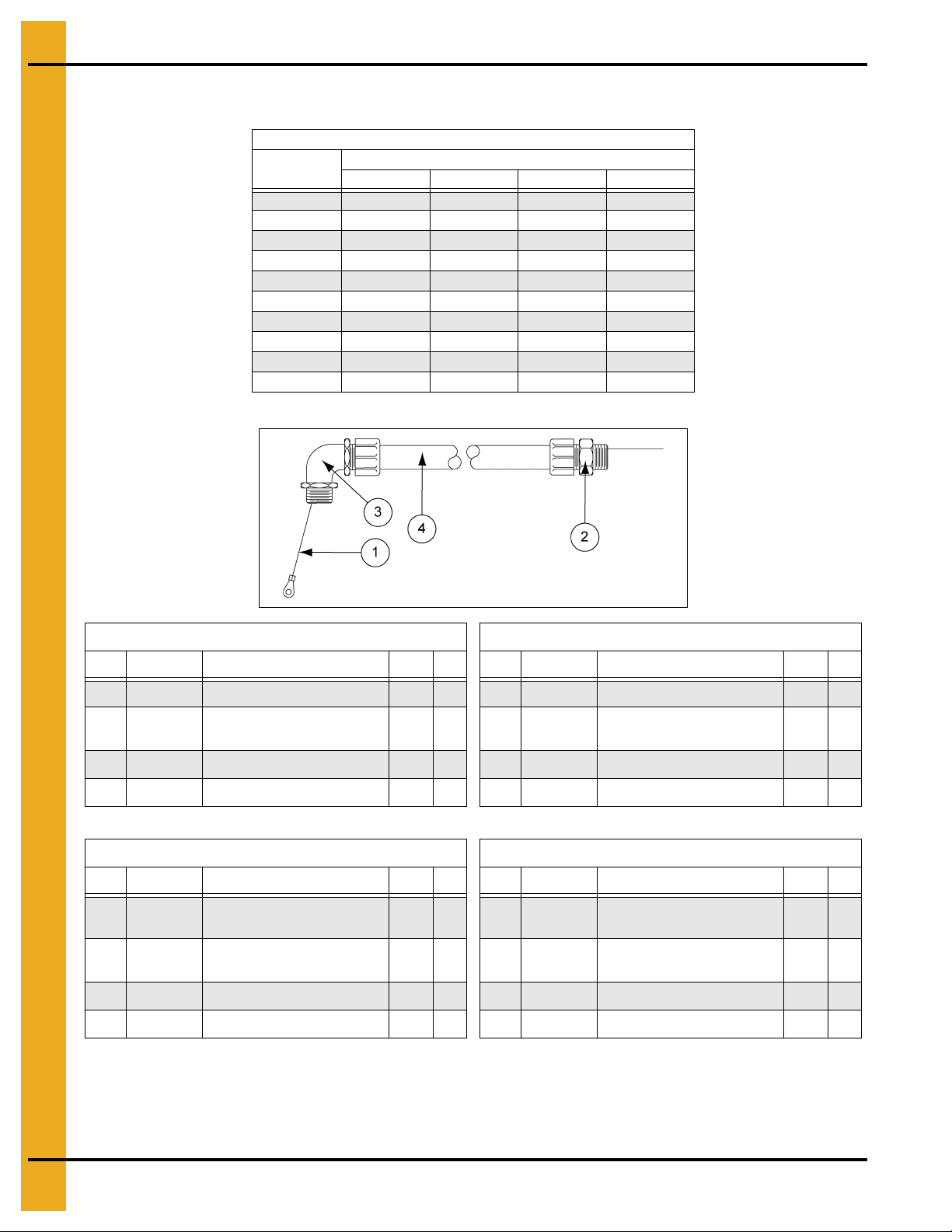
7. Parts List
Motor Conduit Assembly
Fan Model
CF-3 C-8236 C-8236 C-8236 C-8236
CF-5 C-8236 C-8236 C-8236 C-8568
CF-7.5 C-8236 C-8236 C-8236 C-8236
CF-10 C-8240 C-8236 C-8236 C-8240
CF-15 C-8240 C-8240 C-8240 C-8656
CF-20 - C-8240 C-8240 C-8240
CF-25 - C-8239 C-8239 C-8239
CF-30 - C-8239 C-8239 C-8239
CF-40 - C-8239 C-8239 C-8239
CF-50 - C-8239 C-8239 C-8239
1P 230V 3P 230V 3P 460V 3P 575V
Motor Conduit Assembly
Conduit Assembly
C-8236 - Conduit Assembly 3/4" x 31" Str/Elbow C-8665 - Conduit Assembly 1-1/4" x 31" Str/Elbow
Ref # Part # Description Qty U/M
1 067-1044-6 Connector Sealtite STR 3/4" 1 EA 1 006-1187-1 Connector - 1-1/4" Elec 90° Seal 1 EA
2 E305-0160
3 FH-6563 Sealtite 3/4" CSA Approved 2.5833 FT 3 FH-6565 Sealtite 1-1/4" CSA Approved 2.5833 FT
4 TFC-0054 Elbow 3/4" Sealtite CSA 1 EA
C-8239 Conduit Assembly 1-1/2" x 24" Str/Elbow, W
Ref # Part # Description Qty U/M
1 006-1092-3 Connector Sealtite 90° 1-1/2" 1 EA 1 E305-0160
2 E305-0160
3 GT3-0353 Sealtite 1-1/2" 2 FT 3 GT3-0275 Connector Sealtite 90° 2" 1 EA
4 GT3-0354 Connector Sealtite STR 1-1/2" 1 EA
WR 46" (10 Green/Yellow)
1/4/Ring Term
WR 46" (10 Green/Yellow)
1/4/Ring Term
1EA
1EA
Ref # Part # Description Qty U/M
2 E305-0160
4 GT3-0151 Connector Sealtite STR 1-1/4" 1 EA
C-8301 Conduit Assembly 2" x 24" Str/Elbow, W
Ref # Part # Description Qty U/M
2 GT3-0274 Sealtite 2" 2 FT
4 GT3-0331 Connector Sealtite STR 2" 1 EA
WR 46" (10 Green/Yellow)
1/4/Ring Term
WR 46" (10 Green/Yellow)
1/4/Ring Term
1EA
1 EA
60 PNEG-163-08 Centrifugal Fan
Page 61

Motor Conduit Assembly (Continued)
Motor Conduit Assembly
Fan Model
1P 230V 3P 230V 3P 460V 3P 575V
CHS-3 C-8267 C-8265 C-8568 C-8568
CHS-5 C-8264 C-8265C-8568C-8568
CHS-7.5 C-8264 C-8569 C-8568 C-8568
CHS-10 C-8266 C-8569 C-8568 C-8568
CHS-15 - C-8272 C-8571 C-8571
CHS-20 - C-8572 C-8572 C-8572
CHS-30 - C-8309 C-8310 C-8310
CHS-40 - C-8311 C-8310 C-8311
CHS-50 - C-8311 C-8312 C-8311
Conduit Assembly
7. Parts List
C-8264 - Conduit Assembly 3/4" x 36" Str/Elbow 8 C-8266 Conduit Assembly 3/4" x 36" Str/Elbow 6
Ref # Part # Description Qty U/M
1 067-1044-6 Connector Sealtite STR 3/4" 1 EA 1 067-1044-6 Connector Sealtite STR 3/4" 1 EA
2 C-7213 Tape 3/4 x 66' 3M Plastic 0.054 RL
3 C-7214 Tape Rubber Wrap 3/4 x 30' 0.066 RL 3 C-7214 Tape Rubber Wrap 3/4 x 30' 0.066 RL
4 E305-0153
5 FH-6563 Sealtite 3/4" CSA Approved 3 FT 5 FH-6563 Sealtite 3/4" CSA Approved 3 FT
6 FH-6996 Wire Crimp #2011S Buchanan 2 EA
7 FH-6997 Insulator #417 Ideal 2 EA 7 FH-6997 Insulator #417 Ideal 2 EA
8 TFC-0054 Elbow 3/4" Sealtite CSA 1 EA
9 WR-08BK Wire 8 Gauge Stranded THNN Black 4 FT 9 WR-06BK Wire 6 AWG Black, 600V, Type M 4 FT
10 WR-08RD Wire 8 Gauge Stranded THNN Red 4 FT
WR 48" (10 Green/Yellow)
1/4/Ring Term
C-8267 Conduit Assembly 3/4" x 36" Str/Elbow 1
Ref # Part # Description Qty U/M
1 067-1044-6 Connector Sealtite STR 3/4" 1 EA
2 C-7213 Tape 3/4 x 66' 3M Plastic 0.135 RL
3 E305-0153 WR 48" (10 Green/Yellow) 1/4/Ring Term 1 EA
4 E305-0163 WR 48" (12 Black) 1/2/1/2 1 EA
5 E305-0164 WR 48" (12 Red) 1/2/1/2 1 EA
6 FH-6563 Sealtite 3/4" CSA Approved 3 FT
7 FH-6999 Insulator 16 Gauge Insul. Crimp 2 EA
8 TFC-0054 Elbow 3/4" Sealtite CSA 1 EA
1EA
Ref # Part # Description Qty U/M
2 C-7213 Tape 3/4 x 66' 3M Plastic 0.135 RL
4 E305-0153
6 FH-6996 Wire Crimp #2011S Buchanan 2 EA
8 TFC-0054 Elbow 3/4" Sealtite CSA 1 EA
10 WR-06RD Wire 6 Gauge Red 4 FT
WR 48" (10 Green/Yellow)
1/4/Ring Term
1EA
PNEG-163-08 Centrifugal Fan 61
Page 62

7. Parts List
Motor Conduit Assembly (Continued)
Motor Conduit Assembly
Fan Model
CHS-3 C-8267 C-8265 C-8568 C-8568
CHS-5 C-8264 C-8265 C-8568 C-8568
CHS-7.5 C-8264 C-8569 C-8568 C-8568
CHS-10 C-8266 C-8569 C-8568 C-8568
CHS-15 - C-8272 C-8571 C-8571
CHS-20 - C-8572 C-8572 C-8572
CHS-30 - C-8309 C-8310 C-8310
CHS-40 - C-8311 C-8310 C-8311
CHS-50 - C-8311 C-8312 C-8311
1P 230V 3P 230V 3P 460V 3P 575V
Conduit Assembly
C-8265 - Conduit Assembly 3/4" x 36" Str/Elbow 1
Ref # Part # Description Qty U/M
1 067-1044-6 Connector Sealtite STR 3/4" 1 EA 1 067-1044-6 Connector Sealtite STR 3/4" 1 EA
2 E305-0153
3 FH-6510 Washer Reducing 1"-3/4" Electr 2 EA 3 C-7214 Tape Rubber Wrap 3/4 x 30' 0.1333 RL
4 FH-6563 Sealtite 3/4" CSA Approved 3 FT
5 FH-6999 Insulator 16 Gauge Insul. Crimp 4 EA 5 FH-6563 Sealtite 3/4" CSA Approved 3 FT
6 TFC-0054 Elbow 3/4" Sealtite CSA 1 EA
7 WR-14BK Wire 14 Gauge Stranded MTW Black 8 FT 7 FH-6997 Insulator #417 Ideal 4 EA
8 WR-14RD Wire 14 Gauge Stranded MTW Red 4 FT
C-8272 - Conduit Assembly 1" x 60" Str/Elbow 6 Gauge
Ref # Part # Description Qty U/M
1 C-7213 Tape 3/4 x 66' 3M Plastic 0.1818 RL 1 006-1092-3 Connector Sealtite 90° 1-1/2" 1 EA
2 C-7214 Tape Rub ber Wrap 3/4 x 30' 0.1999 RL
3 E305-0267
4 FH-6564 Sealtite 1" CSA Approved 5 FT
5 FH-6996 Wire Crimp #2011S Buchanan 6 EA 5 GT3-0354 Connector Sealtite STR 1-1/2" 1 EA
6 FH-6997 Insulator #417 Ideal 6 EA
7 GT3-0461 Connector Sealtite STR 1" 1 EA 7 WR-02RD Wire 2 Gauge Red Wire 6.5 FT
8 TFH-2029 Sealtite, 1" 90° Fitting 1 EA
9 WR-06BK Wire 6 AWG Black, 600V, Type M 12 FT
10 WR-06RD Wire 6 Gauge Red 6 FT
WR 48" (10 Green/Yellow)
1/4/Ring Term
WR 78" (10 Green/Yellow)
1/4/Ring Term
1EA
Ref # Part # Description Qty U/M
1 EA 3 E305-0267
C-8569- Conduit Assembly 3/4" x 36" Str/Elbow 1
2 C-7213 Tape 3/4 x 66' 3M Plastic 0.1818 RL
4 E305-0153
6 FH-6996 Wire Crimp #2011S Buchanan 4 EA
8 TFC-0054 Elbow 3/4" Sealtite CSA 1 EA
9 WR-10BK Wire 10 Gauge Stranded MTW Black 8 FT
10 WR-10RD Wire 10 Gauge Stranded MTW Red 4 FT
C-8309 - Conduit Assembly 1-1/2" x 60" Str/Elbow 2
Ref # Part # Description Qty U/M
2 C-7215-A GRP - Splice Bolt 2H Blackburn 3 EA
4 GT3-0353 Sealtite 1-1/2" 5 FT
6 WR-02BK Wire 2 Gauge Black Wire 13 FT
WR 48" (10 Green/Yellow)
1/4/Ring Term
WR 78" (10 Green/Yellow)
1/4/Ring Term
1EA
1 EA
62 PNEG-163-08 Centrifugal Fan
Page 63

Motor Conduit Assembly (Continued)
C-8310 - Conduit Assembly 1-1/2" x 60" Str/Elbow 6 C-8311 - Conduit Assembly 2" x 60" Str/Elbow 1 Gauge
7. Parts List
Ref # Part # Description Qty U/M
1 006-1092-3 Connector Sealtite 90° 1-1/2" 1 EA 1 C-7218-A GRP - Splice Bolt 1H3 Blackburn 3 EA
2 C-7213 Tape 3/4 x 66' 3M Plastic 0.2727 RL
3 C-7214 Tape Rubber Wrap 3/4 x 30' 0.1999 RL 3 GT3-0274 Sealtite 2" 5 FT
4 E305-0267
5 FH-6996 Wire Crimp #2011S Buchanan 6 EA 5 GT3-0331 Connector Sealtite STR 2" 1 EA
6 FH-6997 Insulator #417 Ideal 6 EA
7 GT3-0353 Sealtite 1-1/2" 5 FT
8 GT3-0354 Connector Sealtite STR 1-1/2" 1 EA
9 WR-06BK Wire 6 AWG Black, 600V, Type M 13 FT
10 WR-06RD Wire 6 Gauge Red 6.5 FT
WR 78" (10 Green/Yellow)
1/4/Ring Term
1EA
Ref # Part # Description Qty U/M
2 E305-0267
4 GT3-0275 Connector Sealtite 90° 2" 1 EA
6 WR-01BK Wire 1 Gauge Black Stranded CSA 19.5 FT
WR 78" (10 Green/Yellow)
1/4/Ring Ter m
1EA
C-8312 - Conduit Assembly 2" x 60" Str/Elbow 4 Gauge
Ref # Part # Description Qty U/M
1 C-7215-A GRP - Splice Bolt 2H Blackburn 3 EA
2 E305-0267 WR 78" (10 Green/Yellow) 1/4/Ring Term 1 EA
3 FH-6996 Wire Crimp #2011S Buchanan 3 EA
4 FH-6997 Insulator #417 Ideal 3 EA
5 GT3-0274 Sealtite 2" 5 FT
6 GT3-0275 Connector Sealtite 90° 2" 1 EA
7 GT3-0331 Connector Sealtite STR 2" 1 EA
8 WR-04BK Wire 4 Gauge MTW Black 13 FT
9 WR-04RD Wire 4 Gauge Red Wire 6.5 FT
PNEG-163-08 Centrifugal Fan 63
Page 64

7. Parts List
Motor Conduit Assembly (Continued)
Motor Conduit Assembly
Fan Model
CF-30D - C-8439 C-8440
CF-40D - C-8450 C-8438
CF-50D - C-8450 C-8436
1P 230V 3P 230V 3P 460V
Conduit Assembly
C-8572 - Conduit Assembly 1" x 60" Str/Elbow 12 Gauge
Ref # Part # Description Qty U/M
1 C-7213 Tape 3/4 x 66' 3M Plastic 0.1818 RL 1 067-1044-6 Connector Sealtite STR 3/4" 1 EA
2 C-7214 Tape Rubber Wrap 3/4 x 30' 0.133 RL
3 E305-0267
4 FH-6564 Sealtite 1" CSA Approved 5 FT
5 FH-6997 Insulator #417 Ideal 4 EA 5 TFC-0054 Elbow 3/4" Sealtite CSA 1 EA
6 FH-6999 Insulator 16 Gauge Insul. Crimp 6 EA
7 GT3-0461 Connector Sealtite STR 1" 1 EA 8 WR-14RD Wire 14 Gauge Stranded MTW Red 4 FT
8 TFH-2029 Sealtite, 1" 90° Fitting 1 EA
9 WR-12BK Wire 12 Gauge Stranded MTW Black 24 FT
10 WR-12RD Wire 12 Gauge Stranded MTW Red 12 FT
C-8571- Conduit Assembly 3/4" x 60" Str/Elbow 1 C-8439 - GRP-DI Conduit 3P230 #2 1-1/2 x 48
Ref # Part # Description Qty U/M
1 067-1044-6 Connector Sealtite STR 3/4" 1 EA 1 006-1092-3 Connector Sealtite 90° 1-1/2" 1 EA
2 C-7213 Tape 3/4 x 66' 3M Plastic 0.2727 RL
3 C-7214 Tape Rubber Wrap 3/4 x 30' 0.1999 RL 3 E305-0188
4 E305-0188
5 FH-6563 Sealtite 3/4" CSA approved 5 FT 5 GT3-0353 Sealtite 1-1/2" 3 FT
6 FH-6996 Wire Crimp #2011S Buchanan 6 EA
7 FH-6997 Insulator #417 Ideal 6 EA 7 WR-02BK Wire 2 Gauge Black Wire 10 FT
8 TFC-0054 Elbow 3/4" Sealtite CSA 1 EA
9 WR-10BK Wire 10 Gauge Stranded MTW Black 12 FT
10 WR-10RD Wire 10 Gauge Stranded MTW Red 6 FT
WR 78" (10 Green/Yellow)
1/4/Ring Term
WR 60" (10 Green/Yellow)
1/4/Ring Term
1 EA 3 FH-6563 Sealtite 3/4" CSA Approved 3 FT
1EA
C-8568 - Conduit Assembly 3/4" x 36" Str/Elbow 1
Ref # Part # Description Qty U/M
2 E305-0153
4 FH-6999 Insulator 16 Gauge Insul. Crimp 6 EA
7 WR-14BK Wire 14 Gauge Stranded MTW Black 8 F T
Ref # Part # Description Qty U/M
2 C-7218-A GRP - Splice Bolt 1H3 Blackburn 4 EA
4 FH-6997 Insulator #417 Ideal 4 EA
6 GT3-0354 Connector Sealtite STR 1-1/2" 1 EA
8 WR-02RD Wire 2 Gauge Red Wire 5 FT
WR 48" (10 Green/Yellow)
1/4/Ring Term
WR 60" (10 Green/Yellow)
1/4/Ring Term
1EA
1 EA
64 PNEG-163-08 Centrifugal Fan
Page 65

Motor Conduit Assembly (Continued)
C-8450 - GRP-DI Conduit 3P230 #1 2 x 48 C-8440 - GRP-DI Conduit 3P460 #6 1-1/2 x 48
7. Parts List
Ref # Part # Description Qty U/M
1 C-7218-A GRP-Splice Bolt 1H3 Blackburn 3 EA 1 006-1092-3 Connector Sealtite 90° 1-1/2" 1 EA
2 E305-0188
3 GT3-0274 Sealtite 2" 4 FT 3 C-7214 Tape Rubber Wrap 3/4 x 30' 0.1999 RL
4 GT3-0275 Connector Sealtite 90° 2" 1 EA 4 E305-0188
5 GT3-0331 Connector Sealtite STR 2" 1 EA 5 FH-6996 Wire Crimp #2011S Buchanan 6 EA
6 WR-01BK Wire 1 Gauge Black Stranded CSA 15 FT
Ref # Part # Description Qty U/M Ref # Part # Description Qty U/M
1 C-7213 Tape 3/4 x 66' 3M Plastic 0.2727 RL 1 C-7215-A GRP-Splice Bolt 2H Blackburn 3 EA
WR 60" (10 Green/Yellow)
1/4/Ring Term
C-8438 - GRP-DI Conduit 3P460 #6 2 x 48 C-8436 - GRP-DI CONDUIT 3P230 #2 2 x 48
1EA
Ref # Part # Description Qty U/M
2 C-7213 Tape 3/4 x 66' 3M plastic 0.2727 RL
WR 60" (10 Green/Yellow)
1/4/Ring Term
6 FH-6997 Insulator #417 Ideal 6 EA
7 GT3-0353 Sealtite 1-1/2" 3 FT
8 GT3-0354 Connector Sealtite STR 1-1/2" 1 EA
9 WR-06BK Wire 6 AWG Black, 600V, Type M 10 FT
10 WR-06RD Wire 6 Gauge Red 5 FT
1EA
2 C-7214 Tape Rubber Wrap 3/4 x 30' 0.1999 RL 2 E305-0188
3 E305-0188
4 FH-6996 Wire Crimp #2011S Buchanan 6 EA 4 FH-6997 Insulator #417 Ideal 3 EA
5 FH-6997 Insulator #417 Ideal 6 EA 5 GT3-0274 Sealtite 2" 4 FT
6 GT3-0274 Sealtite 2" 4 FT 6 GT3-0275 Connector Sealtite 90° 2" 1 EA
7 GT3-0275 Connector Sealtite 90° 2" 1 EA 7 GT3-0331 Connector Sealtite STR 2" 1 EA
8 GT3-0331 Connector Sealtite STR 2" 1 EA 8 WR-02BK Wire 2 Gauge Black Wire 10 FT
9 WR-06BK Wire 6 AWG Black, 600V, Type M 10 FT 9 WR-02RD Wire 2 Gauge Red Wire 5 FT
10 WR-06RD Wire 6 Gauge Red 5 FT
WR 60" (10 Green/Yellow)
1/4/Ring Term
1 EA 3 FH-6996 Wire Crimp #2011S Buchanan 3 EA
WR 60" (10 Green/Yellow)
1/4/Ring Term
1EA
PNEG-163-08 Centrifugal Fan 65
Page 66
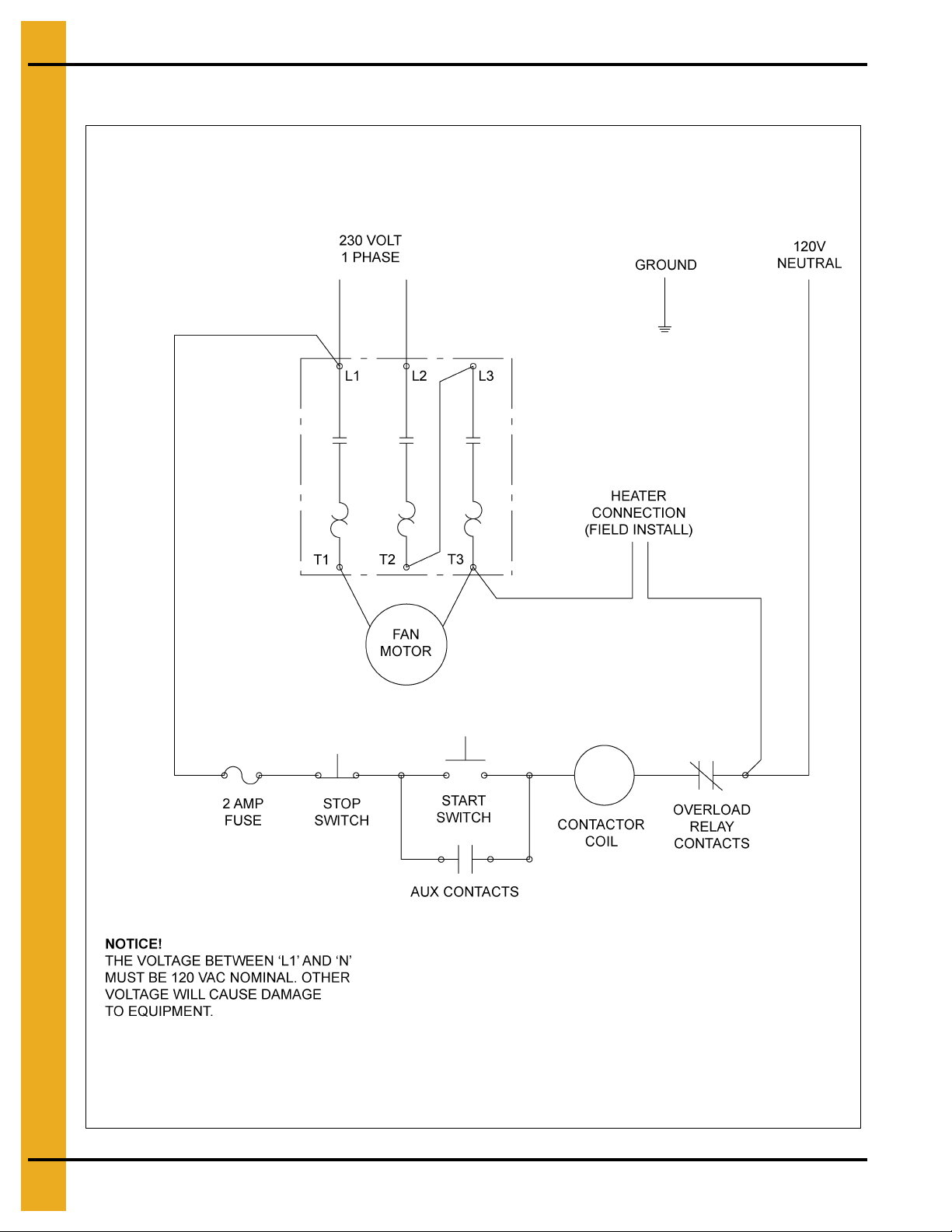
8. Schematics/Wiring Diagrams
Wiring Schematic - 230 Volt 1 Phase
66 PNEG-163-08 Centrifugal Fan
Page 67

8. Schematics/Wiring Diagrams
Motor Part # Capacitor Part # Capacitor Type MFD Voltage Qty
CF-3-1 Capacitor Specifications
FH-7012 Electrolytic 161 250 1
C-7979
FH-5474 FH-7013 Electrolytic 850 115 1
C-7980
FH-5476
FH-5478
C-7981
C-7982
FH-7000 Electrolytic 216 250 1
FH-7011 Oil 35 370 1
CHS-3-1 Capacitor Specifications
CF-5-1 Capacitor Specifications
FH-7000 Electrolytic 216 250 2
CH-6898 Oil 40 370 1
FH-7012 Electrolytic 216 250 2
CH-6898 Oil 40 370 1
FH-7000 Electrolytic 216 250 2
FH-7010 Oil 25 370 1
CF-7.5-1 Capacitor Specifications
FH-7000 Electrolytic 216 250 2
CH-6898 Oil 40 370 1
CF-10-1 Capacitor Specifications
FH-7000 Electrolytic 216 250 3
CH-6898 Oil 40 370 3
FH-5480
C-7982
C-7983
CHS-10-1 Capacitor Specifications
FH-7000 Electrolytic 216 250 3
CH-6897 Oil 30 370 2
CF-15-1 Capacitor Specifications
FH-7000 Electrolytic 216 250 3
CH-6899 Oil 50 370 3
FH-7000 Electrolytic 215 250 3
CH-6899 Oil 50 370 3
PNEG-163-08 Centrifugal Fan 67
Page 68

8. Schematics/Wiring Diagrams
Wiring Diagram - CHS-3-1C
CHS-3-1 Capacitor Specifications
Motor Part # Capacitor Part # Capacitor Type MFD Voltage Qty
FH-5474 FH-7013 Electrolytic 850 115 1
68 PNEG-163-08 Centrifugal Fan
Page 69

8. Schematics/Wiring Diagrams
Wiring Diagram - CF-10-1C and CHS-10-1C
Motor Part # Capacitor Part # Capacitor Type MFD Voltage Qty
CHS-10-1 Capacitor Specifications
FH-5480
C-7981
PNEG-163-08 Centrifugal Fan 69
FH-7000 Electrolytic 216 250 3
CH-6897 Oil 30 370 2
CF-7.5-1 Capacitor Specifications
FH-7000 Electrolytic 216 250 2
CH-6898 Oil 40 370 1
Page 70

8. Schematics/Wiring Diagrams
Wiring Diagram - CF-15-1C
Motor Part # Capacitor Part # Capacitor Type MFD Voltage Qty
CF-10-1 Capacitor Specifications
C-7982
C-7982
C-7983
FH-7000 Electrolytic 216 250 3
CH-6898 Oil 40 370 3
CF-15-1 Capacitor Specifications
FH-7000 Electrolytic 216 250 3
CH-6899 Oil 50 370 3
FH-7000 Electrolytic 215 250 3
CH-6899 Oil 50 370 3
70 PNEG-163-08 Centrifugal Fan
Page 71

8. Schematics/Wiring Diagrams
Wiring Diagram - CF-5-1C, CF-7.5-1C, CHS-5-1C and CHS-7.5-1C
Motor Part # Capacitor Part # Capacitor Type MFD Voltage Qty
CF-3-1 Capacitor Specifications
FH-7012 Electrolytic 161 250 1
C-7979
C-7980
FH-5476
FH-5478
FH-7000 Electrolytic 216 250 1
FH-7011 Oil 35 370 1
CF-5-1 Capacitor Specifications
FH-7000 Electrolytic 216 250 2
CH-6898 Oil 40 370 1
FH-7012 Electrolytic 216 250 2
CH-6898 Oil 40 370 1
FH-7000 Electrolytic 216 250 2
FH-7010 Oil 25 370 1
PNEG-163-08 Centrifugal Fan 71
Page 72

8. Schematics/Wiring Diagrams
Wiring Schematic - 230 Volt 3 Phase
72 PNEG-163-08 Centrifugal Fan
Page 73

Wiring Diagram - 230 Volt 3 Phase
NOTE: Refer to Chart below to determine which connection diagram to use.
8. Schematics/Wiring Diagrams
Fan Model Motor Connection Diagram Fan Model Motor Connection Diagram
CF-3 CD0005 CHS-3 CD0005
CF-5 CD0005 CHS-5 CD0005
CF-7.5 CD0005 CHS-7.5 CD0005
CF-10 CD0005 CHS-10 CD0005
CF-15 CD0005 CHS-15 CD0005
CF-20 CD0180 CHS-20 CD0005
CF-25 CD0005 CHS-30 CD0005
CF-30 CD0005 CHS-40 CD0180
CF-40 CD0005 CHS-50 CD0180
CF-50 CD0005
PNEG-163-08 Centrifugal Fan 73
Page 74

8. Schematics/Wiring Diagrams
Wiring Schematic - 460 Volt 3 Phase
74 PNEG-163-08 Centrifugal Fan
Page 75

Wiring Diagram - 460 Volt 3 Phase
8. Schematics/Wiring Diagrams
PNEG-163-08 Centrifugal Fan 75
Page 76

9. Appendix A
Double Inlet Fans
NOTE: Refer to supplements provided by component manufacturers for installation and maintenance
of the double inlet fan bearings and shaft coupling.
PNEG-1436 INSTRUCTIONS - DODGE GRIP-TIGHT
PNEG-1437 INSTRUCTIONS - REXNORD COUPLING
76 PNEG-163-08 Centrifugal Fan
Page 77

10. Warranty
9101239_1_CR_rev7.DOC (revised July 2009)
GSI Group, LLC Limited Warranty
The GSI Group, LLC (“GSI”) warrants products which it manufactures to be free of defects in materials and workmanship
under normal usage and conditions for a period of 12 months after sale to the original end-user or if a foreign sale,
14 months from arrival at port of discharge, whichever is earlier. The end-user’s sole remedy (and GSI’s only obligation)
is to repair or replace, at GSI’s option and expense, products that in GSI’s judgment, contain a material defect in materials
or workmanship. Expenses incurred by or on behalf of the end-user without prior written authorization from the GSI
Warranty Group shall be the sole responsibility of the end-user.
Warranty Extensions:
The Limited Warranty period is extended for the following products:
Product Warranty Period
Performer Series Direct Drive Fan Motor 3 Years
AP Fans and Flooring
Cumberland
Feeding/Watering
Systems
Grain Systems Grain Bin Structural Design 5 Years
Grain Systems
Farm Fans
Zimmerman
All Fiberglass Housings Lifetime
All Fiberglass Propellers Lifetime
Feeder System Pan Assemblies 5 Years **
Feed Tubes (1-3/4" and 2.00") 10 Years *
Centerless Augers 10 Years *
Watering Nipples 10 Years *
Portable and Tower Dryers 2 Years
Portable and Tower Dryer Frames and
Internal Infrastructure †
5 Years
* Warranty prorated from list price:
0 to 3 years - no cost to end-user
3 to 5 years - end-user pays 25%
5 to 7 years - end-user pays 50%
7 to 10 years - end-user pays 75%
** Warranty prorated from list price:
0 to 3 years - no cost to end-user
3 to 5 years - end-user pays 50%
† Motors, burner components
and moving parts not included.
Portable dryer screens included.
Tower dryer screens not included.
GSI further warrants that the portable and tower dryer frame and basket, excluding all auger and auger drive components,
shall be free from defects in materials for a period of time beginning on the twelfth (12
and continuing until the sixtieth (60
th
) month from the date of purchase (extended warranty period). During the extended
th
) month from the date of purchase
warranty period, GSI will replace the frame or basket components that prove to be defective under normal conditions
of use without charge, excluding the labor, transportation, and/or shipping costs incurred in the performance of this
extended warranty.
Conditions and Limitations:
THERE ARE NO WARRANTIES THAT EXTEND BEYOND THE LIMITED WARRANTY DESCRIPTION SET FORTH
ABOVE. SPECIFICALLY, GSI MAKES NO FURTHER WARRANTY OF ANY KIND, EXPRESS OR IMPLIED,
INCLUDING, WITHOUT LIMITATION, WARRANTIES OF MERCHANTABILITY OR FITNESS FOR A PARTICULAR
PURPOSE OR USE IN CONNECTION WITH: (I) PRODUCT MANUFACTURED OR SOLD BY GSI OR (II) ANY ADVICE,
INSTRUCTION, RECOMMENDATION OR SUGGESTION PROVIDED BY AN AGENT, REPRESENTA TIVE OR
EMPLOYEE OF GSI REGARDING OR RELATED TO THE CONFIGURATION, INSTALLATION, LAYOUT, SUITABILITY
FOR A PARTICULAR PURPOSE, OR DESIGN OF SUCH PRODUCTS.
GSI shall not be liable for any direct, indirect, incidental or consequential damages, including, without limitation, loss of
anticipated profits or benefits. The sole and exclusive remedy is set forth in the Limited Warranty, which shall not exceed
the amount paid for the product purchased. This warranty is not transferable and applies only to the original end-user. GSI
shall have no obligation or responsibility for any representations or warranties made by or on behalf of any dealer, agent
or distributor.
GSI assumes no responsibility for claims resulting from construction defects or unauthorized modifications to products
which it manufactured. Modifications to products not specifically delineated in the manual accompanying the equipment at
initial sale will void the Limited Warranty.
This Limited Warranty shall not extend to products or parts which have been damaged by negligent use, misuse, alteration,
accident or which have been improperly/inadequately maintained. This Limited Warranty extends solely to products
manufactured by GSI.
Prior to installation, the end-user has the responsibility to comply with federal, state and local codes which apply to the
location and installation of products manufactured or sold by GSI.
PNEG-163-08 Centrifugal Fan 77
Page 78

This equipment shall be installed in accordance with
the current installation codes and applicable
regulations which should be carefully followed in all
cases. Authorities having jurisdiction should be
consulted before installations are made.
Copyright © 2013 by GSI Group
Printed in the USA
GSI Group
1004 E. Illinois St.
Assumption, IL 62510-0020
Phone: 1-217-226-4421
Fax: 1-217-226-4420
www.gsiag.com
CN-304481
 Loading...