

Page 1
Series II Sweep
FAQs (Frequently Asked Questions)
PNEG-1618
Date: 03-21-08
PNEG-1618
Page 2

2 PNEG-1618 Series II Sweep
Page 3
1. Series II Sweep - FAQs
FAQs
Who do I contact for parts or service?
Contact your dealer. If your unit was purchased direct from GSI, contact your inside sales person.
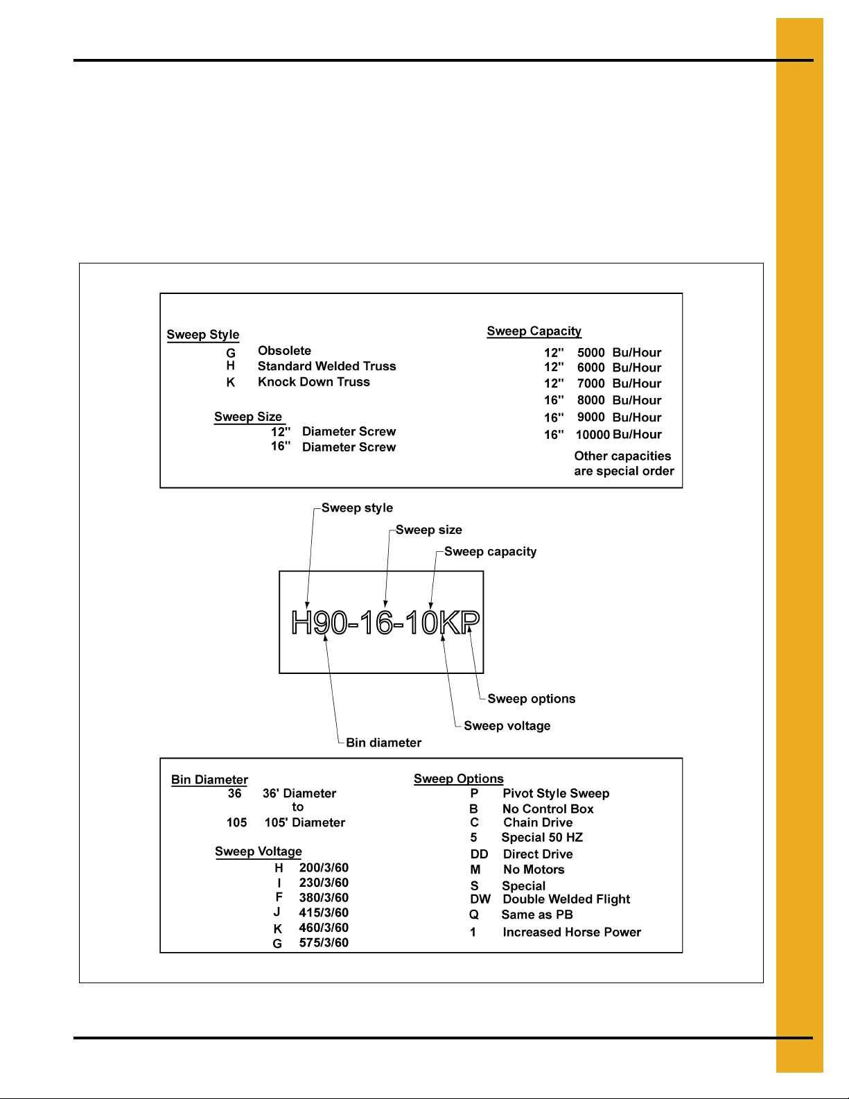
What is/where do I find the model number of my sweep?
The model number of your sweep can be found on your quote or invoice. A space is provided at the
front of your manual to record this number.
The model number code is as follows:
Figure 1A
Pneg-1618 Series II Sweep 3
Page 4

1. Series II Sweep - F AQs
Do I want to buy a pivot or a standard sweep? What is the difference?
The following drawing (Figure 1B) is of a 16" pivot sweep head end weldment and a 16" standard
sweep head end weldment. There are very few differences between the two. The standard head
weldment has the female pivot tube welded to the drive end of the unit. Two (2) plate braces and one
(1) pipe brace support this tube. The pivot head weldment has a lug welded to the underside of the
motor mount plate. This lug is for attachment of the sweep pivot rod assembly. There is a large hole
in the rear plate for the center support tube assembly to pass through. Next to the large hole is a slot
that the center support mounts to.
Figure 1B
How complete is the Series II Sweep?
With the exception of a few electrical connectors, all components required to assemble your sweep
are included.
How level does my floor need to be for the sweep to operate properly?
The top edge of the sump hopper and the top edge of the “X” brace support must be level with the
floor. The floor must be level within 3/4" plus or minus, preferably less. Any high or low points must
be gradually sloped. The change in elevation should be no more than 3/4" over 60".
Where should the center pivot pin be located?
The center pin or pivot pipe must be in the center of the bin. If it is not, the sweep could hit the bin
wall. There should be between 2" and 14" of clearance between the end of the sweep and the closest
obstruction (bin wall, stiffeners, etc.).
How round must my bin be for the sweep to operate properly?
Diameter tolerances are limited by foundation limits and sweep operatio n as well as structural issues.
For 72' diameter and larger bins, the overall tolerance would be plus or minus 1-1/4" on the radius,
plus or minus 1" on 42'-66' diameter bins and plus or minus 3/4" on 30'-39' bins.
4 Pneg-1618 Series II Sweep
Page 5

1. Series II Sweep - FAQs
How large of an opening do I need for a standard flow (15000 BPH) center sump?
If installing a 12" standard sweep (non-pivot), the minimum recommended sump opening is 36" x
36". With a 16" standard sweep, it is 42" x 42".
If installing a 12" standard sweep with a pivot kit, the minimum recommended sump opening is 36" x
36". With a 16" standard sweep, it is 42" x 42". The cross brace (spider) is designed to fit a standard
42" x 42" sump, but the arms can be cut by the customer to fit a smaller opening. The top of the
sump center brace weldment must be level with the top of the floor.
If installing a GSI supplied sump shell with collector ring, the opening must be 42-1/2" x 42-1/2" x 30"
deep for either the 12" or 16" sweep.
The sump hopper supplied by GSI was designed with sufficient clearance around the collector ring
housing to allow grain to gravity flow through the hopper and be carried away by the material
handling equipment below it. 42-3/4" is the maximum opening size to allow rolling clearance for the
casters assembled to the head end jack. If the sump is made smaller, grain flow may decrease to an
unacceptable level.
Figure 1C
The open area of this sump is misleading. The collector ring housing sticks down into the sump,
blocking off a portion of the flow. Also, the sweep covers about one quarter of the opening at the t op.
We use 75% of the theoretical flow around the housing for the actual flow.
What intermediate sump spacing do I need? Why?
It is required to install the intermediate sumps on a maximum of 10' centers where the sweep will be
parked during storage. The first intermediate sump should be placed a maximum of 10' on center
from the center sump and the end sump should be no farther than 4' from the bin wall. The extra
sumps will help clean out the grain in front of the sweep, reducing the start-up load. Doing this will
save labor dollars and hours of work to dig out the sweep and will help the sweep during start-up.
The sweep is not designed to start-up when submerged in material. The sweep should be parked
behind the intermediate sumps with the sumps on the auger side of the sweep.
Do I need to clean out around the end of the sweep prior to starting it up?
Enough material must be removed from around the tractor drive and the screw drive units to allow
access to the motor/drive covers. Both the chain drive and the belt drive must be free of grain before
and during operation.
Pneg-1618 Series II Sweep 5
Page 6

1. Series II Sweep - F AQs
Where do I park the sweep before I fill the bin with grain?
There is a section in the Manual PNEG-720-G2 and PNEG-720-KD called “Storage Preparation”.
The section says to “Park the sweep behind the intermediate sumps, so that the sumps are on the
auger side of the sweep”. The sweep should not completely cover the inside sump hole (the one
closest to the center sump). You will have to clean out around the tractor drive and the jack wheels
before operation.
Where do I find the track dimensions?
The wheel path dimensions are listed at the front of the owner’s manual. Your dealer also has a copy
of the path dimensions in his price book. The head jack wheels are not listed on the chart. These are
always 34" from the center of the bin. The area around the center sump must be kept clear for the
head jack wheels to roll.
What do I need to hook electrical power to the Series II Sweep?
The Series II Sweep is designed to operate using 460 Volt 3 Phase 60 Cycle Power. The voltage
must be within plus or minus 4% for proper operation. Voltages outside of this range may cause
excessive power draw or other operating problems. Please contact the factory for applications
outside of these parameters.
A fused main power disconnect switch capable of being locked only in the OFF position should be
used. This switch must be sized for the screw and tractor drive motors. The power must be locked
out before servicing the equipment, entering the bin, or resetting the motor overloads.
The disconnect and the wiring to the GSI supplied control box is the owner’s responsibility and is not
included with the sweep.
Electrical controls and wiring should be installed by a qualified electrician. The motor disconnect
switches and conductor cables should comply with the National Electrical Code and any st ate or local
codes which may apply.
How does the Series II Sweep operate?
The Series II Sweep is designed with a small controller in the control panel door to monitor the load
on the screw motor. It automatically shuts the tractor drive OFF when the screw motor reaches a
percentage of the motor nameplate full load amperage. As the material clears the screw, the
amperage lowers until it reaches a set value and the tractor drive turns back on and moves the screw
into the material. The customer must program the setpoints into the controller and this setup is fully
explained in the Owner’s Manual. We usually start the high setpoint at approximately 90% of full load
amps (FLA) listed on the motor nameplate and the low setpoint at 60% of the FLA.
Can I use the same control panel for different size sweeps?
If the different size sweeps use the same size motors, the same control panel can be used for
different sweeps. The controller must be reprogrammed for each sweep.
Why does the controller need to be located at the bin door?
The control panel MUST be mounted OUTSIDE the bin near the door for safety reasons. It must be
located so the operator has a full view of the equipment. It must NEVER be installed inside the bin.
Why do I need a foot switch?
The foot switch has to be plugged into the control panel and depressed before the sweep is
operational. It has a 10' cord so the sweep can only be monitored from OUTSIDE the bin.
6 Pneg-1618 Series II Sweep
Page 7

1. Series II Sweep - FAQs
Can I just run my sweep in the manual mode?
The Series II Sweep is designed to run in the automatic mode. If the sweep is run in the manual
mode, either of the motors may overheat and/or become damaged. Also, excessive amounts of
material may spill over the back board of the sweep.
How do I set my overloads?
The overloads for both motors are adjustable and are not set at the factory. The overload inside the
control panel has a small, usually yellow, dial with numbers on it. Record the full load running amp
value listed on the nameplate attached to each motor. Increase the full load amp value by 10% and
set this number on the overload dial. If the adjustable overloads are set too low, the motors will shut
down as soon as a load is put on them. Disconnect and lock out the power before resetting the motor
overloads.
When do I program my controller?
Initially the sweep should be tested in the manual mode. If it operates properly, then move on to try
the automatic mode.
How do I program my controller for automatic mode?
The Owner’s Manual has a detailed set of instructions describing the setup of automatic mode. The
final programming must be performed with material in the tank.
What are the four receptacles in the bottom of the control panel for?
The four receptacles in the bottom of the control box are for the screw drive power, the tractor drive
power, the motor overloads and the foot switch. Each receptacle is keyed differently to prevent
mixing the cables.
Figure 1D
Why doesn’t the auger run while tractor drive is in reverse?
This is a safety feature of the Series II Sweep.
Can I get the unit to reverse while in automatic?
No. This is another safety feature of the Series II Sweep.
Pneg-1618 Series II Sweep 7
Page 8

1. Series II Sweep - F AQs
What do I do if I encounter any operational problems?
Disconnect and lock out the power before servicing the equipment, entering the bin, or resetting the
motor overloads. Look through the troubleshooting section in the Manual PNEG-720-G2 and PNEG720-KD to identify any problems.
There does not seem to be any power to my sweep. What do I do?
Check to be sure the foot switch is plugged into the control panel and depressed. The foot switch has
a 10' cord so the sweep can only be monitored from OUTSIDE the bin.
The thermal protection cord must be connected and plugged in before the sweep will operate.
Your electrician should check to make sure there are no loose or shorted connections or wires. It is
possible that one of the components failed after it was tested in our plant and needs to be replaced.
A jobsite electrician can isolate any malfunctioning components. Each fuse should also be checked
and replaced if necessary.
The sweep must be wired according to the Owner/Installation Manuals.
The overload for the screw drive keeps tripping. What do I do?
The overloads for both motors are adjustable. These are not set at the factory prior to delivery and
installation. The overload inside the control panel has a small, usually yellow , dial with numbers on it.
Record the full load running amp value listed on the nameplate attached to each motor. Increase the
full load amp value by 10% and set this number on the overload dial. If the adjustable overloads are
set too low, the motors will shut down as soon as a load is put on them. Disconnect and lock out the
power before resetting the motor overloads.
Check the incoming power at the control box. The Series II Sweep is designed to operate using
460 Volt 3 Phase 60 Cycle Power. The voltage must be within plus or minus 4% for proper
operation. Voltages outside of this range may cause excessive power draw or other operating
problems. Please contact the factory for applications outside of these parameters.
Check the incoming power at the motor. Check for balanced phases. If the loads are not properly
balanced between leads, disconnect the motor and check the power leads. By using this method, we
can tell if the imbalance is caused by the motor or is from the incoming power.
The sweep must be wired according to the Owner/Installation Manuals.
My tractor drive seems to start and stop too often in automatic. What do I do?
The HYS A (High setpoint minus low setpoint) may be set with too large a number. To get maximum
capacity from the sweep, this number should be set as small as possible and not have grain spill over
the sweep backboard.
My controller quits operating. What do I do?
Check to make sure the controller has power. Each of the fuses should be checked and replaced if
required.
If the controller is functioning, it may need to be reprogrammed. Programming instructions are
included in the manual that shipped with the sweep. The controller can be damaged by large power
fluctuations or lightning strikes.
My sweep is not operating as well as it did the last time I used it. What do I do?
If the type of material or the density (moisture) of the material changes, the controller setpoints may
need to be adjusted for maximum output.
8 Pneg-1618 Series II Sweep
Page 9

1. Series II Sweep - FAQs
Is there any maintenance I need to perform on the electrical system?
None of the electrical components require maintenance. Be sure to disconnect and lock out the
power before servicing the equipment, entering the bin, or resetting the motor overloads.
Does any part of the Series II Sweep need lubrication?
The fluid level of each of the gear reducers must be checked before operation. These reducers may
have been shipped dry and require oil before operation.
A complete lubrication section is provided in the Owner’s Manual, which shows the type and amount
of lubricant to be used and which components need to be lubricated.
What maintenance should I perform and how often?
Follow the lubrication instructions in the Owner’s Manual. Also visually inspect the sweep before
operation.
What should I visually inspect?
Starting from the drive end of the sweep:
Inspect the head jack, caster mounting channel and head casters. Look for any bent or damaged
components.
Inspect the motor covers. They should be in good shape and should be used properly. If the covers
are not used, the material will work its way into the motor cooling slots and when the sweep is
started, the motor fan and housing will be destroyed.
Inspect the belt guard for damage. Make sure there is no material inside the belt guard. The drain
pan at the bottom of the guard can be used if required.
Inspect the drive belts, sheaves and bushings. Check the belts for proper tension. Sheaves and
bushings should be tight.
Inspect the intermediate jacks for any broken or damaged components. Check the jack wheels for
damage. The jacks should operate freely.
Inspect each of the screw flight bearings and hangers for damage. Check to see if the bearings need
to be replaced. All hardware should be tight.
Inspect the screw flights for damage or excessive wear. Check to see if the screws are rusted or pitted.
Inspect the end bearing for damage.
Inspect the end caster (if one was originally supplied) to confirm it is working properly or if it needs to
be replaced.
Inspect the tractor drive chain guard for damage. Make sure there is no material (grain) inside the
chain guard. If there is any material (grain), drain pan which is at the bottom of the guard can be
used to empty the guard.
Inspect the drive chain for damage and proper lubrication. Check for proper tension and confirm
the sprockets and bushings are tight.
Inspect the tractor drive tires for damage or tread wear. Be sure the lug nuts are tight and tires are
installed with the tread direction as shown in the manual.
Inspect the bearings for damage or excessive wear. Replace if necessary.
Inspect the tractor drive motor and gear reducer for damage or excessive wear.
Make sure all hardware is tight.
Inspect the sweep structure for damaged or bent components.
Pneg-1618 Series II Sweep 9
Page 10

This equipment shall be installed in accordance with
the current installation codes and applicable
regulations which should be carefully followed in all
cases. Authorities having jurisdiction should be
consulted before installations are made.
Copyright © 2008 by GSI Group
Printed in the USA
GSI Group
1004 E. Illinois St.
Assumption, IL 62510-0020
Phone: 1-217-226-4421
Fax: 1-217-226-4420
www.gsiag.com
 Loading...