

Page 1

PNEG-1615
Heavy Duty Bin Stairs
and Platform Assembly for
4.00" Corrugated Bin
Installation Manual
PNEG-1615
Version: 1.0
Date: 11-08-11
Page 2

2 PNEG-1615 Heavy Duty Bin Stairs and Platform Assembly for 4.00" Corrugated Bin
Page 3

Table of Contents
Contents
Chapter 1 Safety .....................................................................................................................................................4
Safety Guidelines ......... ... ...................................................................................................................... 4
Safety Instructions ..................... ... .... ................................................ ... ... .... ........................................... 5
Chapter 2 Installation ............................................................................................................................................7
Platform Wall Brackets, Stair Wall Brackets and Knee Braces ........................................ ... .... ... ... ........ 7
Assembling the Platform ..................................................................................................................... 12
Assembling the Stairs ......................................................................................................................... 13
Adding the Handrails ........................................................................................................................... 19
Assembling Intermediate Platform (Optional Package #STR1143) .................................................... 22
Chapter 3 Warranty ..............................................................................................................................................25
PNEG-1615 Heavy Duty Bin Stairs and Platform Assembly for 4.00" Corrugated Bin 3
Page 4
1. Safety
This is the safety alert symbol. It is used to alert you
to potential personal injury hazards. Obey all safety
messages that follow this symbol to avoid possible
injury or death.
WARNING indicates a hazardous situation which, if not
avoided, could result in death or serious injury.
CAUTION, used with the safety alert symbol, indicates a
hazardous situation which, if not avoided, could result in
minor or moderate injury.
NOTICE is used to address practices not related to
personal injury.
DANGER indicates a hazardous situation which, if not
avoided, will result in death or serious injury.
Safety Guidelines
This manual contains information that is important for you, the owner/operator, to know and understand.
This information relates to protecting personal safety and preventing equipment problems. It is the
responsibility of the owner/operator to inform anyone operating or working in the area of this equipment
of these safety guidelines. To help you recognize this information, we use the symbols that are defined
below. Please read the manual and pay attention to these sections. Failure to read this manual and its
safety instructions is a misuse of the equipment and may lead to serious injury or death.
DANGER
WARNING
CAUTION
NOTICE
4 PNEG-1615 Heavy Duty Bin Stairs and Platform Assembly for 4.00" Corrugated Bin
Page 5
1. Safety
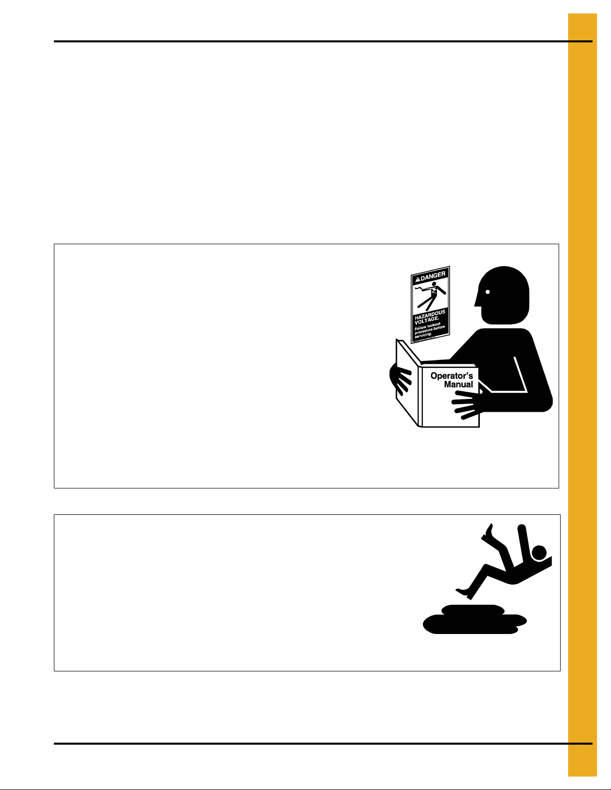
Follow Safety Instructions
Carefully read all safety messages in this manual and
safety signs on your machine. Keep signs in good
condition. Replace missing or damaged safety signs. Be
sure new equipment components and repair parts include
the current safety signs. Replacement safety signs are
available from the manufacturer.
Learn how to operate the machine and how to use controls
properly. Do not let anyone operate without instruction.
Keep your machinery in proper working condition.
Unauthorized modifications to the machine may impair
the function and/or safety and affect machine life.
If you do not understand any part of this manual or need
assistance, contact your dealer.
Read and Understand Manual
Practice Safe Maintenance
Understand service procedures before doing work. Keep area
clean and dry.
Never lubricate, service, or adjust machine while it is in operation.
Keep hands, feet, and clothing away from rotating parts.
Keep all parts in good condition and properly installed. Fix
damage immediately . Replace worn or broken p arts. Remove any
built-up grease, oil, and debris.
Maintain Equipment
and Work Area
Safety Instructions
Our foremost concern is your safety and the safety of others associated with this equipment. We want to
keep you as a customer. This manual is to help you understand safe operating procedures and some
problems that may be encountered by the operator and other personnel.
As owner and/or operator, it is your responsibility to know what requirements, hazards, and precautions
exist, and to inform all personnel associated with the equipment or in the area. Safety precautions may be
required from the personnel. Avoid any alterations to the equipment. Such alterations may produce a very
dangerous situation where SERIOUS INJURY or DEATH may occur.
This equipment shall be installed in accordance with the current installation codes and applicable
regulations, which should be carefully followed in all cases. Authorities having jurisdiction should be
consulted before installations are made.
PNEG-1615 Heavy Duty Bin Stairs and Platform Assembly for 4.00" Corrugated Bin 5
Page 6
1. Safety
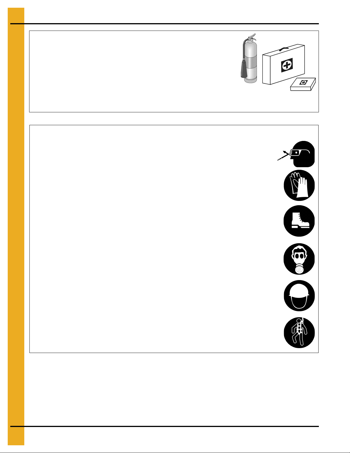
Prepare for Emergencies
Be prepared if fire starts.
Keep a first aid kit and fire extinguisher handy.
Keep emergency numbers for doctors, ambulance service,
hospital, and fire department near your telephone.
Keep Emergency Equipment
Quickly Accessible
Wear Protective Clothing
Wear close-fitting clothing and safety equipment appropriate
to the job.
Remove all jewelry.
Tie long hair up and back.
Wear safety glasses at all times to protect eyes from debris.
Wear gloves to protect your hands from sharp edges on
plastic or steel parts.
Wear steel-toed boots to help protect your feet from falling
debris. Tuck in any loose or dangling shoestrings.
A respirator may be needed to prevent breathing potentially
toxic fumes and dust.
Wear a hard hat to help protect your head.
Wear appropriate fall protection equipment when working at
elevations greater than six feet (6').
Eye Protection
Gloves
Steel-Toed Boots
Respirator
Hard Hat
Fall Protection
6 PNEG-1615 Heavy Duty Bin Stairs and Platform Assembly for 4.00" Corrugated Bin
Page 7
2. Installation
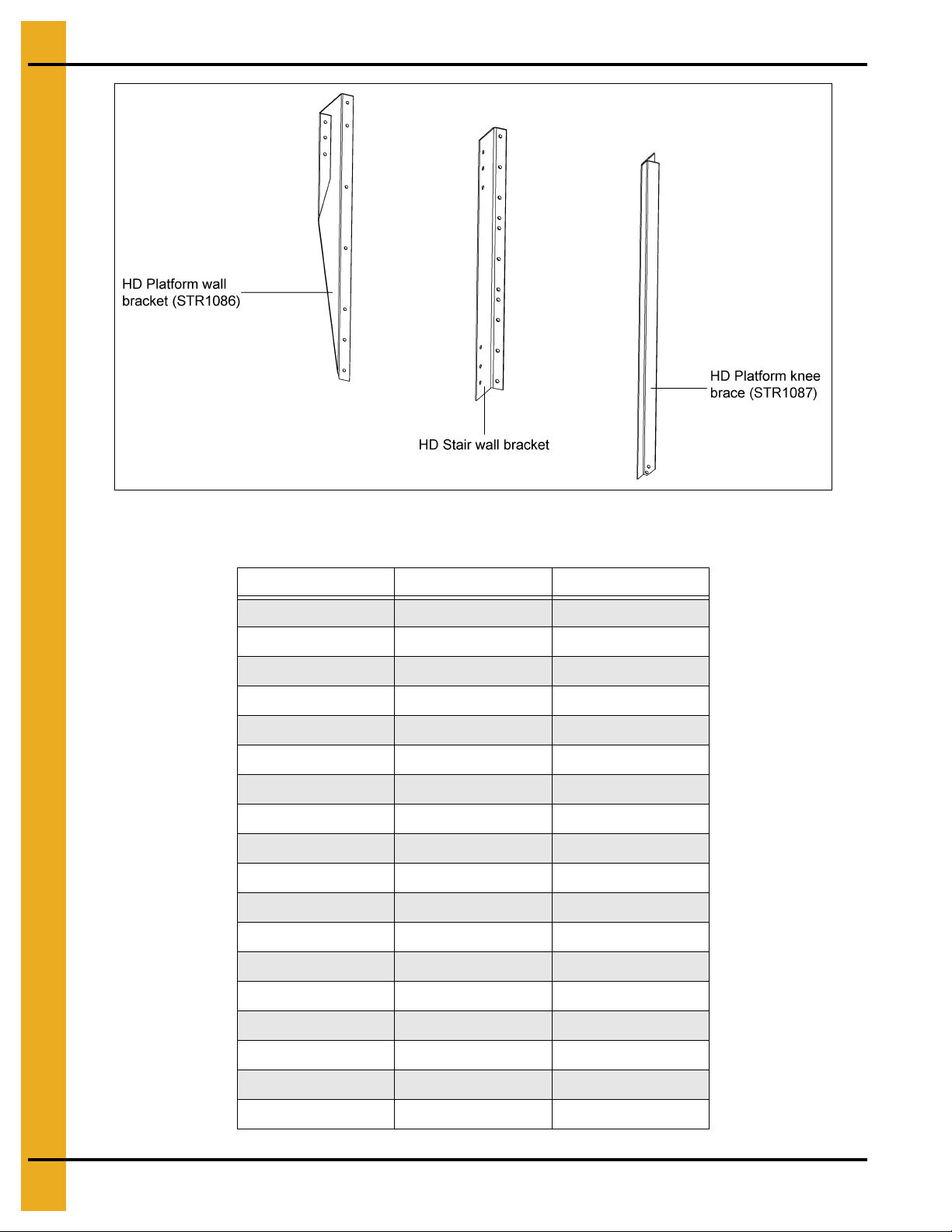
Platform Wall Brackets, Stair Wall Brackets and Knee Braces
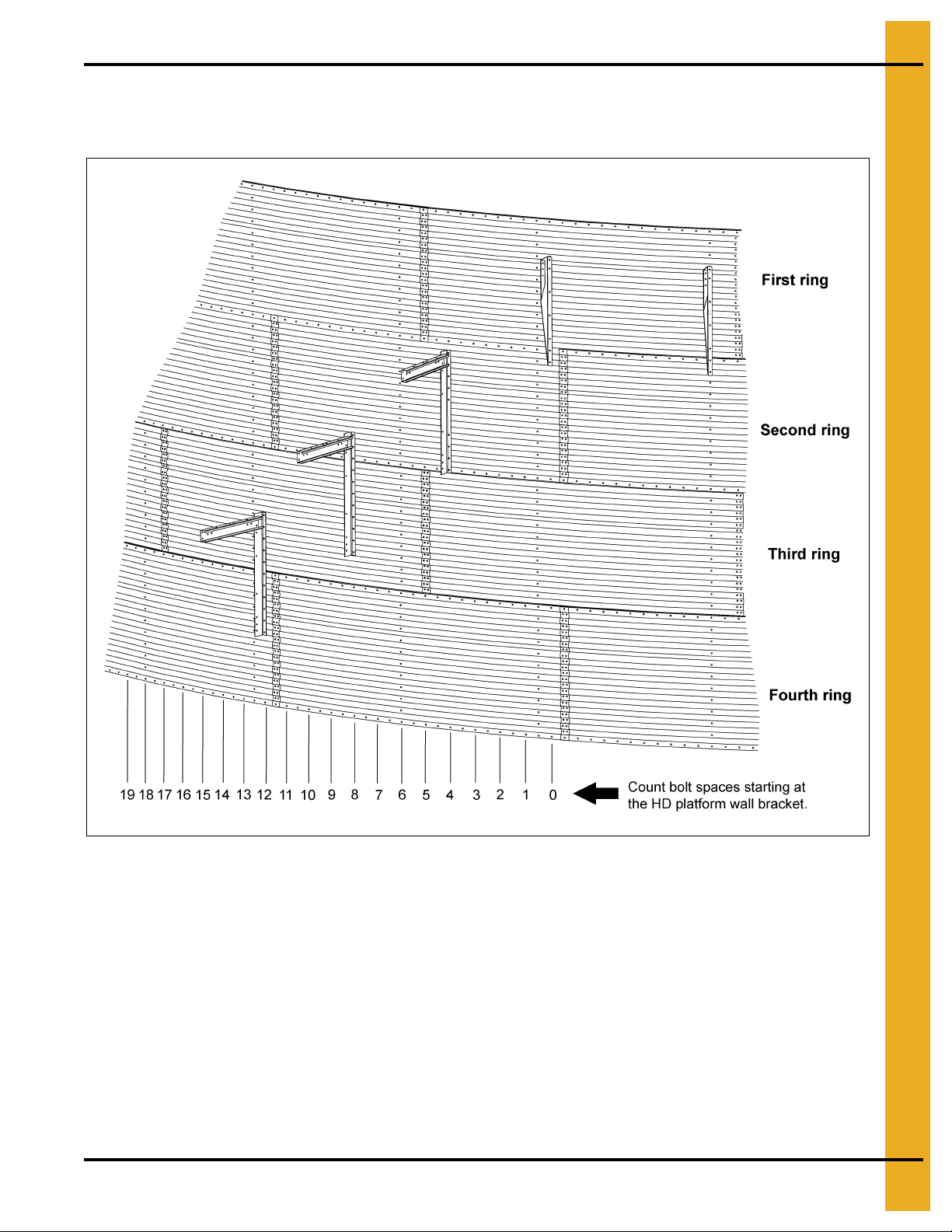
1. Determining the layout of the bin stairs. (See Figure 2A.)
Figure 2A Bin Bolt Spacing
2. Locate the platform directly under the roof ladder and manway hole. The location of the platform and
manhole must be pre-determined so that the stairs will not interfere with auger, doors, fans, etc.
To determine the stair locations, count the number of bolt spaces around the bin according to the
chart on Page 8. This will give the ending lo cation of the stairs. Each step is 8" tall and wraps around
the bin one bolt spacing or 9-3/8". NOTE: One bolt spacing is the distance between the bolts on
the horizontal seams, which is equal to 9-3/8". On a 4.00" (44" sheet) corrugated bin, the first ring
will have the platform at 16" below the eave and a four (4) step section directly below the platform.
3.5 of these first four (4) steps will be within the first ring. There are 5.5 steps for each ring there after
and the (5.5) stairs wrap around the bin (5.5) bolt spaces or 51.5625" per ring. The stairs will be
assembled in four (4) step sections. Use the chart on Page 8 to determine how many bolt spaces
you must allow for the steps during installation.
PNEG-1615 Heavy Duty Bin Stairs and Platform Assembly for 4.00" Corrugated Bin 7
Page 8
2. Installation
Figure 2B
Bolt Spaces around Bin with 4.00" Corrugation
Rings Bolt Spaces Inches
4 20 187-1/2
5 25 234-3/8
6 31 290-5/8
7 36 337-1/2
8 42 393-3/4
9 47 440-5/8
10 53 496-7/8
1 1 58 543-3/4
12 64 600.000
13 69 646-7/8
14 75 703-1/8
15 80 750.000
16 86 806-1/4
17 91 853-1/8
18 97 909-3/8
19 102 956-1/4
20 108 1012-1/2
21 113 1059-3/8
8 PNEG-1615 Heavy Duty Bin Stairs and Platform Assembly for 4.00" Corrugated Bin
Page 9

2. Installation
3. The attachment location of the platform wall bracket to the first horizontal seam is shown in
Figure 2C. Attach the platform wall bracket to the first horizontal seam using the second hole from
the bottom as shown in Figure 2C. This will locate the platform 16" below the eave. The platform wall
brackets are placed six (6) bolt spaces apart or 56-1/4". Loosely attach the platform wall brackets to
the first seam using 5/16" x 3/4" bin bolts and flange nuts.
Figure 2C
PNEG-1615 Heavy Duty Bin Stairs and Platform Assembly for 4.00" Corrugated Bin 9
Page 10

2. Installation
Figure 2D
10 PNEG-1615 Heavy Duty Bin Stairs and Platform Assembly for 4.00" Corrugated Bin
Page 11

2. Installation
Figure 2E
4. Field drill two (2) holes per platform bracket as shown and use 5/16" x 3/4" bin bolts and flange nuts
at the top connection points. The bottom connection points will also be used for the platform knee
brace during platform installation.
5. Four (4) step sections will be placed following the placement of the platform. Therefore, the
first stair wall bracket is placed four (4) bolt spaces around the bin on the second ring as shown in
Figure 2C on Page 9. Loosely attach using two (2) 5/16" x 3/4" bin bolts and flange nuts. Attach the
vertical wall bracket to the bin in at least three (3) places. Two (2) holes will need to be field drilled
for attachment. Drill the two (2) attachment points as shown in Figure 2C on Page 9 and use the
same hardware here.
6. Each additional stair wall bracket (STR1079) will be placed 32" below the previous and four (4)
standard bolt spaces or 37-1/2" from the previous. There will be a total of four (4) steps for each
additional section. Refer to Figure 2C on Page 9 through Figure 2E for vertical wall bracket
placement. Be sure and attach the vertical wall bracket to the bin in at least three (3) places.
PNEG-1615 Heavy Duty Bin Stairs and Platform Assembly for 4.00" Corrugated Bin 11
Page 12

2. Installation
Assembling the Platform
1. Figure 2F shows the assembly of the platform supports. Use 5/16" hardware at all the connection
points. Note the center floor brace (LS-6701) is offset from the center of the platform. (The bin wall
is hidden for clarity.)
Figure 2F
2. Figure 2G shows the assembly of the platform floor, toe plate and vertical angles. This must all be
assembled at the same time using 5/16" hardware. Note the color codes, placement and orientation
of the platform vertical angles.
Figure 2G
12 PNEG-1615 Heavy Duty Bin Stairs and Platform Assembly for 4.00" Corrugated Bin
Page 13

2. Installation
3. Figure 2H shows the assembly of the platform handrails. These must also be attached using
5/16" hardware.
Figure 2H
Assembling the Stairs
1. Figure 2I shows the assembly of the HD stairs. The ends of the steps are bolted under and behind
the step using 5/16" x 3/4" truss head bolt and nut.
Figure 2I
PNEG-1615 Heavy Duty Bin Stairs and Platform Assembly for 4.00" Corrugated Bin 13
Page 14

2. Installation
2. Figure 2J shows the assembly of the stair bracing. As shown before in Figure 2C on Page 9, the first
vertical wall bracket will be located four (4) bolt spaces or 37-1/2" around the bin. 3/8" Hardware is
used at the four (4) connection points as shown. The outer two (2) mounting holes on the side and
the outer middle hole on the top of the horizontal wall bracket will be used to attach the step as shown
in Figure 2K.
Figure 2J Stair Bracing Inside View
Figure 2K Stair Bracing Outside View
14 PNEG-1615 Heavy Duty Bin Stairs and Platform Assembly for 4.00" Corrugated Bin
Page 15

2. Installation
Use standard steps (Refer to Figure 2I
on Page 13 for assembly instructions.)
Bin diameters up to 60'
3.
Figure 2L
and refer to
for the size bin. These illustrations will show how to align the holes on the attachment tabs with the
slots of the next step. Attach the tie straps on the inside and outside of the steps as shown in
shows the assembly of the top four (4) steps. Use 5/16" hardware at the connection points
Figure 2M, Figure 2N, Figure 2O
and
Figure 2M on Pages 15-16
for hole and slot usage
Figure 2L
.
PNEG-1615 Heavy Duty Bin Stairs and Platform Assembly for 4.00" Corrugated Bin 15
Figure 2L
Figure 2M
Page 16

2. Installation
Bin diameters 60' to 72'
Bin diameters 75' to 78'
Bin diameters 90' to 105'
Figure 2N
Figure 2O
Figure 2P
16 PNEG-1615 Heavy Duty Bin Stairs and Platform Assembly for 4.00" Corrugated Bin
Page 17

2. Installation
Continue with standard four (4) step packages
(Refer to Figure 2I on Page 13.)
4. Figure 2Q shows the addition of the next step stair section. The fifth step attaches to the wall bracket
as shown in Figure 2K on Page 14. Use the holes and slots to connect the stairs as shown in the
Figure 2M, Figure 2N, Figure 2O and Figure 2P on Pages 15-16. Continue attaching tie straps on
the inside and outside of the steps.
PNEG-1615 Heavy Duty Bin Stairs and Platform Assembly for 4.00" Corrugated Bin 17
Figure 2Q
Page 18

2. Installation
Horizontal
bracket
(LDR-4083)
5/16" x 3/4" Truss head bolts
Attachment tab
5/16" x 3/4" Truss
head bolt and nut
Tie strap
(STR1078)
Figure 2R Horizontal Bracket to Step
Figure 2S Brace Strap Connection
5. Continue adding four (4) step sections until you have reached the bottom of the bin. Each of the next
wall brackets will be placed 32" lower and four (4) bolt spaces or 37-1/2" around the bin farther than
the previous bracket. See Figure 2C, Figure 2D and Figure 2E on Pages 9-11 for reference.
6. The last section to be placed on the bin will be a special bottom step section. It will include a
14" bottom wall bracket (STR1082). Use this bracket to attach the last step to the bin. An
extra brace may need to be field fabricated to tie the outside of the last step into the concrete.
18 PNEG-1615 Heavy Duty Bin Stairs and Platform Assembly for 4.00" Corrugated Bin
Page 19

2. Installation
Adding the Handrails
1. Figure 2T shows the addition of the handrail posts. Use two (2) 3/8" x 1" flange bolts and nuts to
attach the handrail post to the horizontal wall bracket. Make sure the post is plumb before tightening
the bolts.
Figure 2T
PNEG-1615 Heavy Duty Bin Stairs and Platform Assembly for 4.00" Corrugated Bin 19
Page 20

2. Installation
Handrail post
(LDR-4085)
Two (2) 3/8" x 1" Flange
head bolts and nuts
5/16" x 1-1/4"
Bolt and nut
Figure 2U Handrail Post Connection to Horizontal Wall Bracket
2. Begin installation with the upper handrail. The handrail for the first two (2) steps should be loosely
bolted to the first post and checked to ensure it is the right length. Excess length of the narrow end
of the handrail may need to be cut off and a new hole drilled for connection to the top platform
handrail. Use 5/16" x 1-1/4" bolts at the connections. Continue down the stairs installing handrail
sections to the handrail posts. Extra force maybe needed to curve the handrail on smaller diameters.
Refer to Figure 2V below and Figure 2W on Page 21 for connections.
Figure 2V Upper Handrail Connection
20 PNEG-1615 Heavy Duty Bin Stairs and Platform Assembly for 4.00" Corrugated Bin
Page 21

2. Installation
5/16" x 1-1/4"
Bolt and nut
Four (4) step
handrail (STR1077)
5/16" x 1-1/4" Bin
bolt and nut
Small intermediate
handrail (LDR-4088)
Large intermediate
handrail (LDR-4087)
Figure 2W Upper Handrail Connection
3. After installing the top handrails, the intermediate handrails can be put into place. They will use
the top hole in the middle of the handrail post with 5/16" x 1-1/4" bolts and nut. (See Figure 2T on
Page 19.) The large tube should be placed on the upper handrail post a nd the small tube should be
slid into it and placed on the lower handrail post. The very top intermediate handrail connecting the
platform to the first post may need to be shortened. Equal amounts should be cut from both of
the handrails.
PNEG-1615 Heavy Duty Bin Stairs and Platform Assembly for 4.00" Corrugated Bin 21
Figure 2X Intermediate Handrail
Page 22

2. Installation
Assembling Intermediate Platform (Optional Package #STR1143)
1. The intermediate platform wall brackets and bordering stair section wall brackets should be arranged
as shown in Figure 2Y. The first platform bracket should be placed three (3) bolt spaces around the
bin and 32" below the previous stair wall bracket. The next platform bracket should be placed six (6 )
bolt spaces around the bin at the same height as the previous platform bracket. The next stair wall
bracket is placed four (4) bolt spaces around the bin and 32" below the second platform wall bracket.
In each instance, the wall brackets should be attached to the bin with three (3) bolts. One hole will
have to be drilled in the bin sidewall at the third bolt’s location.
Figure 2Y
2. Figure 2Z shows the assembly of the platform supports. Use 5/16" hardware at all the connection
points. Note the center floor brace (LS-6701) is offset from the center of the platform. (The bin wall
is hidden for clarity.)
Figure 2Z
22 PNEG-1615 Heavy Duty Bin Stairs and Platform Assembly for 4.00" Corrugated Bin
Page 23

2. Installation
3. Figure 2AA shows the assembly of the platform floor, toe plate and vertical angles. This must all be
assembled at the same time using 5/16" hardware. Note the orientation of the vertical angles.
Figure 2AA
4. Figure 2AB shows the assembly of the platform handrails. These must also be attached using
5/16" hardware.
Figure 2AB
PNEG-1615 Heavy Duty Bin Stairs and Platform Assembly for 4.00" Corrugated Bin 23
Page 24

2. Installation
5. Figure 2AC shows the addition of the steps. Three (3) steps will be located above the rest platform
and four (4) are located below the rest platform. The first step above the platform will need to be
securely attached to the handrail and toe plate. A field drilled 3/8" hole will need to be placed in the
handrail in line with the slot in the step. Self-tapping screws will need to be placed in the top of the
step for connection to the toe plate.
Figure 2AC
6. Next the handrail posts can be attached as shown in Pages 19-21 of the manual. NOTE: The handrail
for the stair section above the rest platform will need to be cut to length. A hole will have to be
drilled in the handrail to attach to the handrail post. It can be attached in the same way as previous
discussed in the manual.
24 PNEG-1615 Heavy Duty Bin Stairs and Platform Assembly for 4.00" Corrugated Bin
Page 25

3. Warranty
9101239_1_CR_rev7.DOC (revised July 2009)
GSI Group, LLC Limited Warranty
The GSI Group, LLC (“GSI”) warrants products which it manufactures to be free of defects in materials and workmanship
under normal usage and conditions for a period of 12 months after sale to the original end-user or if a foreign sale,
14 months from arrival at port of discharge, whichever is earlier. The end-user’s sole remedy (and GSI’s only obligation)
is to repair or replace, at GSI’s option and expense, products that in GSI’s judgment, contain a material defect in materials
or workmanship. Expenses incurred by or on behalf of the end-user without prior written authorization from the GSI
Warranty Group shall be the sole responsibility of the end-user.
Warranty Extensions:
The Limited Warranty period is extended for the following products:
Product Warranty Period
Performer Series Direct Drive Fan Motor 3 Years
AP Fans and Flooring
Cumberland
Feeding/Watering
Systems
Grain Systems Grain Bin Structural Design 5 Years
Grain Systems
Farm Fans
Zimmerman
All Fiberglass Housings Lifetime
All Fiberglass Propellers Lifetime
Feeder System Pan Assemblies 5 Years **
Feed Tubes (1-3/4" and 2.00") 10 Years *
Centerless Augers 10 Years *
Watering Nipples 10 Years *
Portable and Tower Dryers 2 Years
Portable and Tower Dryer Frames and
Internal Infrastructure †
5 Years
* Warranty prorated from list price:
0 to 3 years - no cost to end-user
3 to 5 years - end-user pays 25%
5 to 7 years - end-user pays 50%
7 to 10 years - end-user pays 75%
** Warranty prorated from list price:
0 to 3 years - no cost to end-user
3 to 5 years - end-user pays 50%
† Motors, burner components
and moving parts not included.
Portable dryer screens included.
Tower dryer screens not included.
GSI further warrants that the portable and tower dryer frame and basket, excluding all auger and auger drive components,
shall be free from defects in materials for a period of time beginning on the twelfth (12
and continuing until the sixtieth (60
th
) month from the date of purchase (extended warranty period). During the extended
th
) month from the date of purchase
warranty period, GSI will replace the frame or basket components that prove to be defective under normal conditions
of use without charge, excluding the labor, transportation, and/or shipping costs incurred in the performance of this
extended warranty.
Conditions and Limitations:
THERE ARE NO WARRANTIES THAT EXTEND BEYOND THE LIMITED WARRANTY DESCRIPTION SET FORTH
ABOVE. SPECIFICALLY, GSI MAKES NO FURTHER WARRANTY OF ANY KIND, EXPRESS OR IMPLIED,
INCLUDING, WITHOUT LIMITATION, WARRANTIES OF MERCHANTABILITY OR FITNESS FOR A PARTICULAR
PURPOSE OR USE IN CONNECTION WITH: (I) PRODUCT MANUFACTURED OR SOLD BY GSI OR (II) ANY ADVICE,
INSTRUCTION, RECOMMENDATION OR SUGGESTION PROVIDED BY AN AGENT, REPRESENTA TIVE OR
EMPLOYEE OF GSI REGARDING OR RELATED TO THE CONFIGURATION, INSTALLATION, LAYOUT, SUITABILITY
FOR A PARTICULAR PURPOSE, OR DESIGN OF SUCH PRODUCTS.
GSI shall not be liable for any direct, indirect, incidental or consequential damages, including, without limitation, loss of
anticipated profits or benefits. The sole and exclusive remedy is set forth in the Limited Warranty, which shall not exceed
the amount paid for the product purchased. This warranty is not transferable and applies only to the original end-user. GSI
shall have no obligation or responsibility for any representations or warranties made by or on behalf of any dealer, agent
or distributor.
GSI assumes no responsibility for claims resulting from construction defects or unauthorized modifications to products
which it manufactured. Modifications to products not specifically delineated in the manual accompanying the equipment at
initial sale will void the Limited Warranty.
This Limited Warranty shall not extend to products or parts which have been damaged by negligent use, misuse, alteration,
accident or which have been improperly/inadequately maintained. This Limited Warranty extends solely to products
manufactured by GSI.
Prior to installation, the end-user has the responsibility to comply with federal, state and local codes which apply to the
location and installation of products manufactured or sold by GSI.
PNEG-1615 Heavy Duty Bin Stairs and Platform Assembly for 4.00" Corrugated Bin 25
Page 26

This equipment shall be installed in accordance with
the current installation codes and applicable
regulations, which should be carefully followed in all
cases. Authorities having jurisdiction should be
consulted before installations are made.
Copyright © 2011 by GSI Group
Printed in the USA
GSI Group
1004 E. Illinois St.
Assumption, IL 62510-0020
Phone: 1-217-226-4421
Fax: 1-217-226-4420
www.gsiag.com
CN-206055
 Loading...