

Page 1
PNEG-1597
Sweep Tractor and Control Panel
Assembly Instructions
Instruction Manual
PNEG-1597
Date: 02-20-13
Page 2

Personnel operating or working around this equipment should read this manual. This manual
must be delivered with equipment to its owner. Failure to read this manual and its safety
instructions is a misuse of the equipment. Any misuse of the equipment may void the warranty.
2 PNEG-1597 Sweep Tractor and Control Panel Assembly Instructions
Page 3

Table of Contents
Contents
Chapter 1 Introduction ..........................................................................................................................................4
General Information .............................................................................................................................. 4
Chapter 2 Safety .....................................................................................................................................................5
Safety Guidelines .................................................................................................................................. 5
Safety Instructions ..................... ... .... .......................................... ... ... ..................................................... 6
Operator Qualifications ....................................................................................... .... ... ... ... ..................... 9
Chapter 3 Safety Decals ......................................................................................................................................10
Chapter 4 Assembly ............................................................................................................................................11
Sweep Tractor Assembly ....................................... ... .... ... ... ... .......................................... ... ................ 11
End Wheel Assembly ... .......................................... ... .... ... ... ... .... ... ...................................................... 21
Sweep Tractor to Shield Assembly ........ ... ... ....................................................................................... 22
Chapter 5 Operation ............................................................................................................................................23
Programming ....................................... ................ ................... ................ ................. ............................ 23
Chapter 6 Control Panel Diagrams ................................. ...................... ....................... .......................................28
Sweep Tractor Control Box Definitions ......................................... ... ... ... .... ... ... ... .... ... ... ... ... .... ............ 28
Commercial Sweep Control Panel .................................. ... .... ......................................... .... ... ... ... ....28
Schematic - Control Panel GCS Sweeps 230V 3 HP (GCSTP2-03) ...............................................29
Schematic - Control Panel GCS Sweeps 230V 5 HP (GCSTP2-05) ...............................................30
Schematic - Control Panel GCS Sweeps 230V 7.5 HP (GCSTP2-75) ............................................31
Schematic - Control Panel GCS Sweeps 230V 10 HP (GCSTP2-10) .............................................32
Schematic - Control Panel GCS Sweeps 460V 3 HP (GCSTP4-03) ...............................................33
Schematic - Control Panel GCS Sweeps 460V 5 HP (GCSTP4-05) ...............................................34
Schematic - Control Panel GCS Sweeps 460V 7.5 HP (GCSTP4-75) ............................................35
Schematic - Control Panel GCS Sweeps 460V 10 HP (GCSTP4-10) .............................................36
Schematic - Control Panel GCS Sweeps 460V 15 HP (GCSTP4-15) .............................................37
Standard Control Panel Assembly 230V 3 Phase .......... ... .... ... ... ... ... .... ... ... ....... ... ... ... ... .... ... ... ... ....38
Standard Control Panel Assembly 460V 3 Phase .......... ... .... ... ... ... ... .... ... ... ....... ... ... ... ... .... ... ... ... ....40
Chapter 7 Parts List .............................................................................................................................................43
Sweep Tractor Parts ........... ... ... ... .... .......................................... ... ... ................................................... 44
Chain Guard Assembly ....................................................................................................................... 46
Drive Motor Assembly ......................................................................................................................... 47
Bearing Stand Assembly ..................................................................................................................... 48
Chapter 8 Warranty ..............................................................................................................................................49
PNEG-1597 Sweep Tractor and Control Panel Assembly Instructions 3
Page 4

1. Introduction
General Information
1. We reserve the right to improve our product whenever possible and practical to do so. We reserve
the right to change, improve and modify products at any time without obligation to make changes,
improvements and modifications on equipment sold previously.
2. The Sweep Tractor has been designed and manufactured to give years of dependable service.
The care and maintenance of this machine will affect the satisfaction and service obtained. By
observing the instructions and suggestions we have recommended, the owner should receive
competent service for many years. If additional information or assistance should be required,
please contact the factory or your local dealer.
3. Receiving Merchandise and Filing Claims
a. When receiving merchandise, it is important to check both the quantity of parts and their
descriptions with the packing list enclosed within each package. All claims for freight damage or
shortage must be made by the consignee within ten (10) days from the date of the occurrence
of freight damage. The consignee should accept the shipment after noting the damage or loss.
For Claims Contact:
GSI Group
1004 E. Illinois St.
Assumption, IL. 62510
Phone: 1-217-226-4421
4 PNEG-1597 Sweep Tractor and Control Panel Assembly Instructions
Page 5
2. Safety
DANGER
WARNING
CAUTION
NOTICE
This is the safety alert symbol. It is used to alert you
to potential personal injury hazards. Obey all safety
messages that follow this symbol to avoid possible
injury or death.
WARNING indicates a hazardous situation which, if not
avoided, could result in death or serious injury.
CAUTION, used with the safety alert symbol, indicates a
hazardous situation which, if not avoided, could result in
minor or moderate injury.
NOTICE is used to address practices not related to
personal injury.
DANGER indicates a hazardous situation which, if not
avoided, will result in death or serious injury.
Safety Guidelines
This manual contains information that is important for you, the owner/operator, to know and understand.
This information relates to protecting personal safety and preventing equipment problems. It is the
responsibility of the owner/operator to inform anyone operating or working in the area of this equipment of
these safety guidelines. To help you recognize this information, we use the symbols that are defined
below. Please read the manual and pay attention to these sections. Failure to read this manual and its
safety instructions is a misuse of the equipment and may lead to serious injury or death.
PNEG-1597 Sweep Tractor and Control Panel Assembly Instructions 5
Page 6

2. Safety
Follow Safety Instructions
Carefully read all safety messages in this manual and
safety signs on your machine. Keep signs in good
condition. Replace missing or damaged safety signs. Be
sure new equipment components and repair parts include
the current safety signs. Replacement safety signs are
available from the manufacturer.
Learn how to operate the machine and how to use controls
properly. Do not let anyone operate without instruction.
Keep your machinery in proper working condition.
Unauthorized modifications to the machine may impair
the function and/or safety and affect machine life.
If you do not understand any part of this manual or need
assistance, contact your dealer.
Read and Understand Manual
Practice Safe Maintenance
Understand service procedures before doing work. Keep area
clean and dry.
Never lubricate, service, or adjust machine while it is in operation.
Keep hands, feet and clothing away from rotating parts.
Keep all parts in good condition and properly installed. Fix
damage immediately . Replace worn or broken p arts. Remove any
built up grease oil and debris.
Maintain Equipment
and Work Area
Safety Instructions
Our foremost concern is your safety and the safety of others associated with this equipment. We want to
keep you as a customer. This manual is to help you understand safe operating procedures and some
problems that may be encountered by the operator and other personnel.
As owner and/or operator, it is your responsibility to know what requirements, hazards, and precautions
exist, and to inform all personnel associated with the equipment or in the area. Safety precautions may be
required from the personnel. Avoid any alterations to the equipment. Such alterations may p roduce a very
dangerous situation where SERIOUS INJURY or DEATH may occur.
This equipment shall be installed in accordance with the current installation codes and applicable
regulations, which should be carefully followed in all cases. Authorities having jurisdiction should be
consulted before installations are made.
6 PNEG-1597 Sweep Tractor and Control Panel Assembly Instructions
Page 7

2. Safety
Prepare for Emergencies
Be prepared if fire starts.
Keep a first aid kit and fire extinguisher handy.
Keep emergency numbers for doctors, ambulance service,
hospital, and fire department near your telephone.
Keep Emergency Equipment
Quickly Accessible
Wear Protective Clothing
Wear close-fitting clothing and safety equipment appropriate
to the job.
Remove all jewelry.
Tie long hair up and back.
Wear safety glasses at all times to protect eyes from debris.
Wear gloves to protect your hands from sharp edges on plastic
or steel parts.
Wear steel-toed boots to help protect your feet from falling
debris. Tuck in any loose or dangling shoestrings.
A respirator may be needed to prevent breathing potentially
toxic fumes and dust.
Wear a hard hat to help protect your head.
Wear appropriate fall protection equipment when working at
elevations greater than six feet (6').
Eye Protection
Gloves
Steel-Toed Boots
Respirator
Hard Hat
Fall Protection
PNEG-1597 Sweep Tractor and Control Panel Assembly Instructions 7
Page 8

2. Safety
Operate Unload Equipment Properly
• Untrained operators subject themselves and others to SERIOUS INJURY
or DEATH. NEVER allow untrained personnel to operate this equipment.
• NEVER work alone.
• Keep children and other unqualified personnel out of the working
area at ALL times. Refer to the Start-Up section of this manual for
diagrams of the work area.
• Make sure ALL equipment is locked in position before operating.
• NEVER start equipment until ALL persons are clear of the work area.
• Keep hands and feet away from the auger intake and other moving parts.
• NEVER attempt to assist machinery operation or to remove trash from equipment while
in operation.
• Be sure all operators are adequately rested and prepared to perform all functions of operating
this equipment.
• NEVER allow any person intoxicated or under the influence of alcohol or drugs to operate
the equipment.
• Make sure someone is nearby who is aware of the proper shut down sequence in the event of an
accident or emergency.
• ALWAYS think before acting. NEVER act impulsively around the equipment.
• NEVER allow anyone inside a bin, truck or wagon which is being unloaded by an auger or
conveyor. Flowing grain can trap and suffocate in seconds.
• Use ample overhead lighting after sunset to light the work area.
• Keep area around intake free of obstacles such as electrical cords, blocks, etc., that might
trip workers.
• NEVER drive, stand or walk under the equipment.
• Use caution not to hit the auger when positioning the load.
• ALWAYS lock out ALL power to the equipment when finished unloading a bin.
• Be aware of pinch points. A pinch point is a narrow area between two surfaces that is likely to trap or
catch objects and so is a potential safety hazard.
Operate Unload
Equipment Safely
8 PNEG-1597 Sweep Tractor and Control Panel Assembly Instructions
Page 9

2. Safety
Operator Qualifications
A. The User/Operator must be competent and experienced to operate auger equipment. Anyone who
works with or around augers must have good common sense in order to be qualified. T hese persons
must also know and meet all other qualifications, such as:
i. Any person who has not read and/or does not understand all operation and safety procedures
is not qualified to operate any auger systems.
ii. Certain regulations apply to personnel operating power machinery. Personnel under the age of
18 years may not operate power machinery, including augers. It is your responsibility, as owner
and/or supervisor, to know what these regulations are in your area or situation.
iii. Unqualified or incompetent persons are to remain out of the work area.
iv. O.S.H.A. (Occupational Safety and Health Administration) regulations state: “At the time of
initial assignment and at least annually thereafter, the employer shall instruct every employee
in the safe operation and servicing of all equipment with which the employee is, or will be
involved”. (Federal Occupational Safety and Health Standards for Agriculture. Subpart D,
Section 1928.57 (a) (6)).
B. As a requirement of O.S.H.A., it is necessary for the employer to train the employee in the safe
operating and safety procedures for this auger. The sign-off sheet is provided for your convenience
and personal record keeping. All unqualified persons are to stay out of the work area at all times. It
is strongly recommended that another qualified person who knows the shut down procedure is in the
area in the event of an emergency.
Date Employee Name Supervisor Name
PNEG-1597 Sweep Tractor and Control Panel Assembly Instructions 9
Page 10
3. Safety Decals
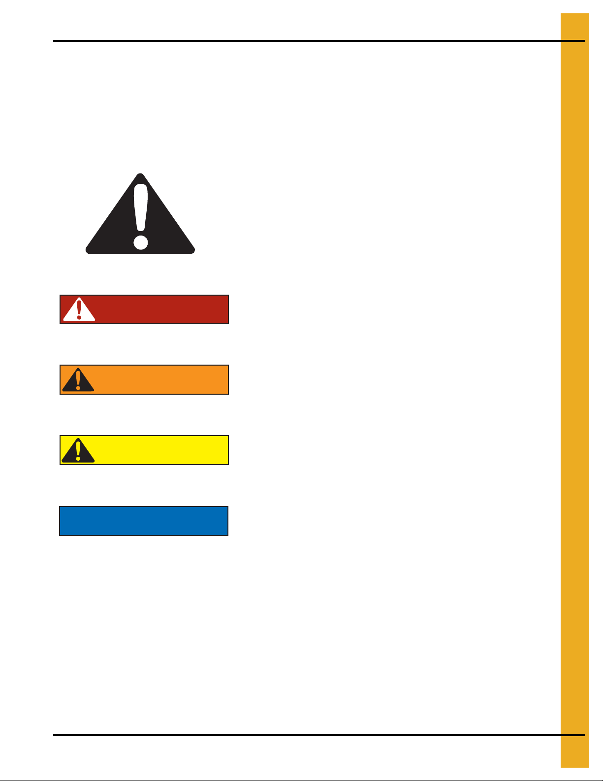
SHEAR POINT
Moving parts can
crush and cut. Keep
hands clear of
sprocket and chain.
DC-1382
DC-1382
Decals located on outside of chain guards.
Check components shown below to ensure that the safety decals are in place and in good co ndition. If a
decal cannot be easily read for any reason or has been painted over, replace it immediately. Contact you r
dealer or the manufacturer to order a replacement decal free of charge.
10 PNEG-1597 Sweep Tractor and Control Panel Assembly Instructions
Page 11
4. Assembly
Sweep Tractor Assembly
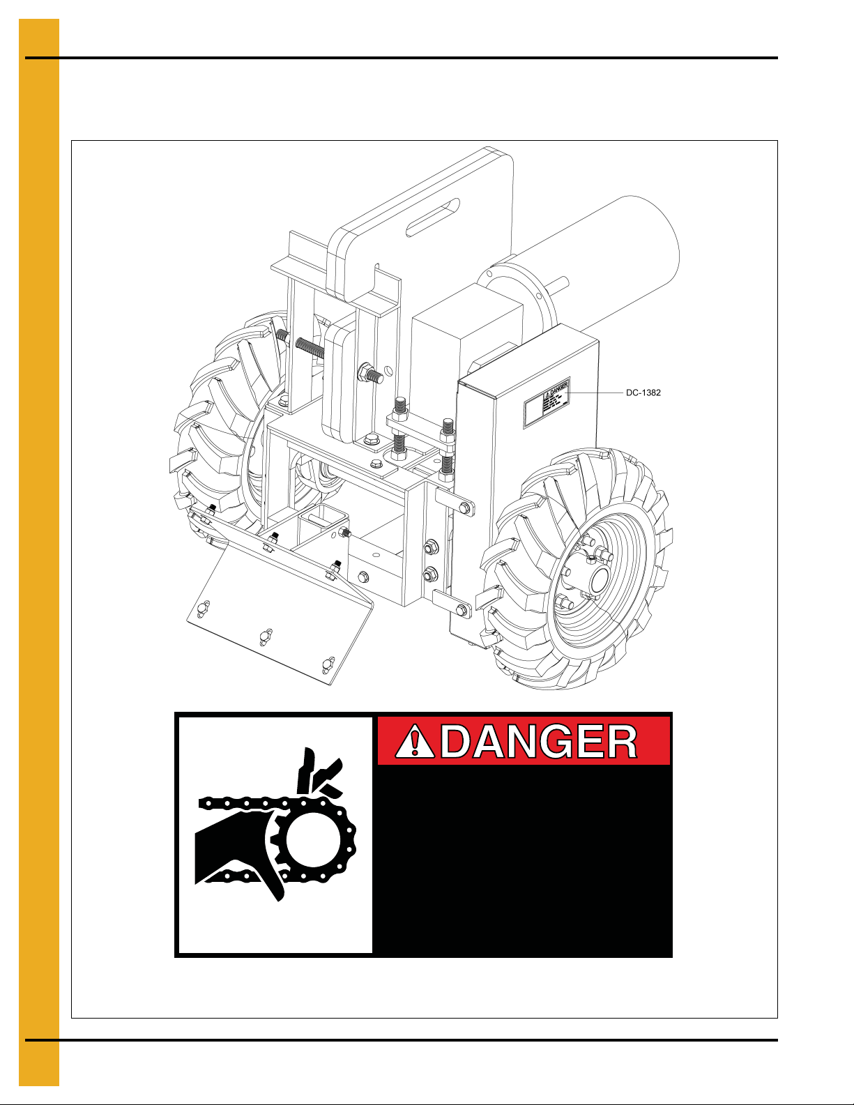
1. Place the tractor frame on plain flat ground.
2. Bolt each pillow block bearing to a bearing mount bracket using two (2) 1/2"-13 x 2" hex head
cap screws, two (2) flat washers and serrated flanged nuts.
3. Bolt each bearing mount bracket to the tractor frame using two (2) 1/2"-13 x 1-1/4" flange bolts and
serrated flanged nuts. (See Figure 4A.)
NOTE: Lock collar flanges for each pillow block bearing must be to the inside of frame.
Figure 4A
PNEG-1597 Sweep Tractor and Control Panel Assembly Instructions 11
Page 12
4. Assembly
NOTE: Lock collars on inside of frame.
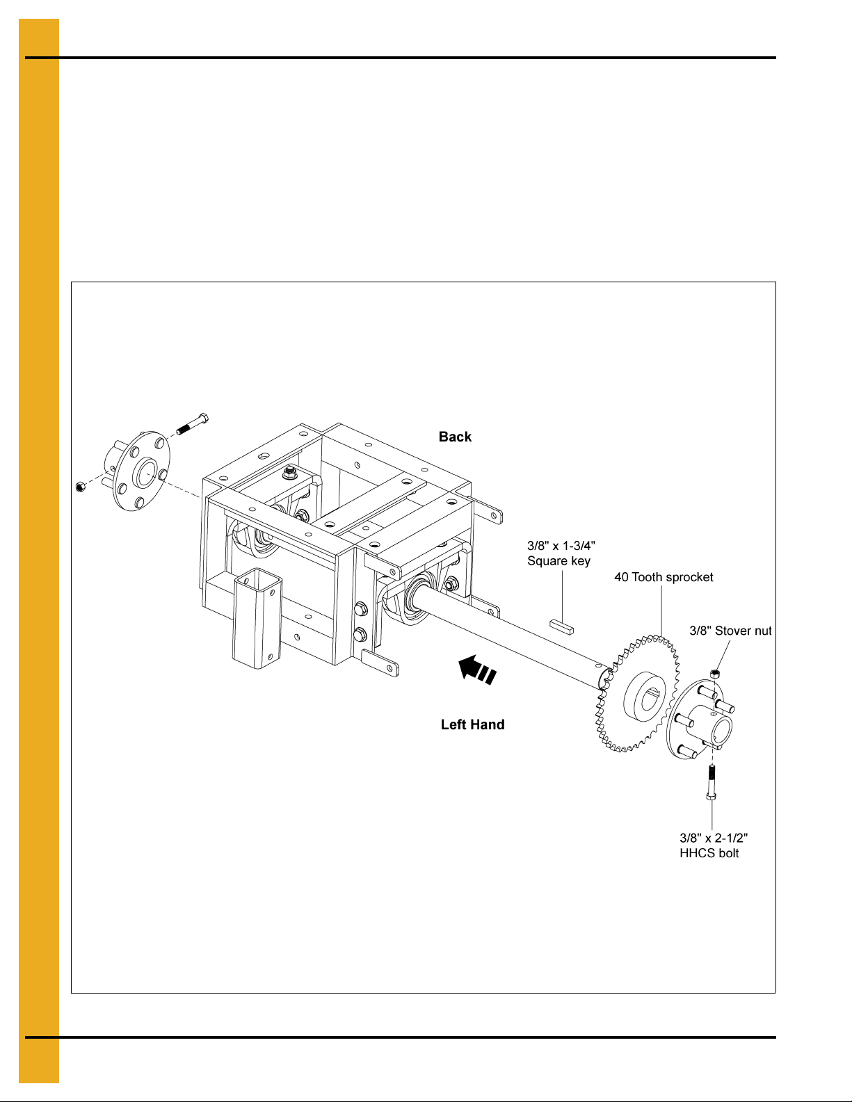
4. Slide the tractor axle through the left side of the pillow block bearing and the lock collars so as to pass
through the right side of the pillow block bearing. Make sure the keyway of the shaft is on the left
hand side of the tractor.
NOTE: Do not tighten the pillow block bearing lock collars yet.
5. Assemble the 40 tooth sprocket to the tractor axle using a 3/8" square x 1-3/4" key. Temporarily
tighten the sprocket to the key and the shaft. Final adjustment of the sprocket placement will occur
after the chain is installed.
6. Mount the wheel hubs to the tractor axle using 3/8"-16 x 2-1/2" hex head cap screws and stover
lock nuts. (See Figure 4B.)
Figure 4B
12 PNEG-1597 Sweep Tractor and Control Panel Assembly Instructions
Page 13
4. Assembly
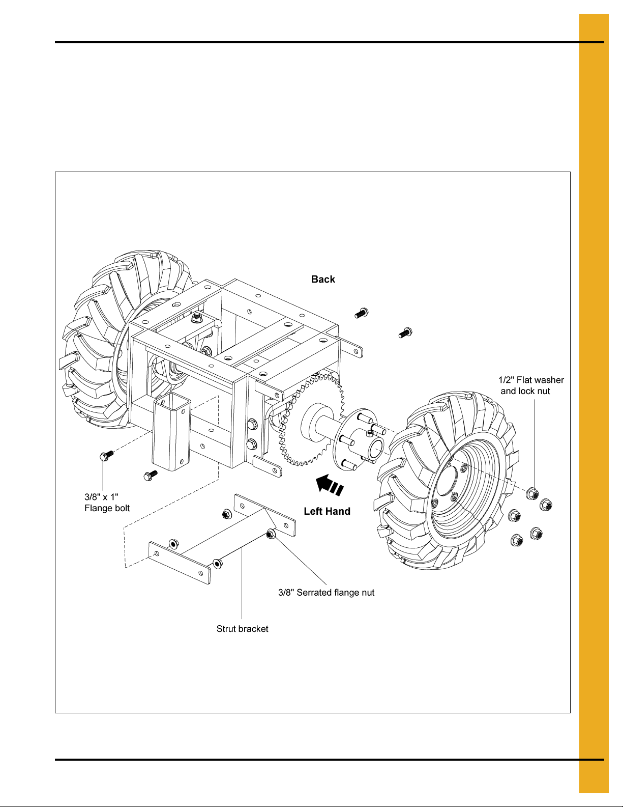
7. Assemble the tire and wheel assemblies securely to the wheel hubs using five (5) 1/2" flat washers
and lock nuts.
NOTE: Remove the screws or nails that are present in the tires to contain the foam in the tires when
they are made. The treads of the tires should be in the forward direction. Figure 4C shows
the proper orientation of the tire and wheel assemblies.
8. Assemble the strut bracket to the tractor frame using four (4) 3/8"-16 x 1" flange bolts and serrated
flange nuts. (See Figure 4C.)
Figure 4C
PNEG-1597 Sweep Tractor and Control Panel Assembly Instructions 13
Page 14
4. Assembly
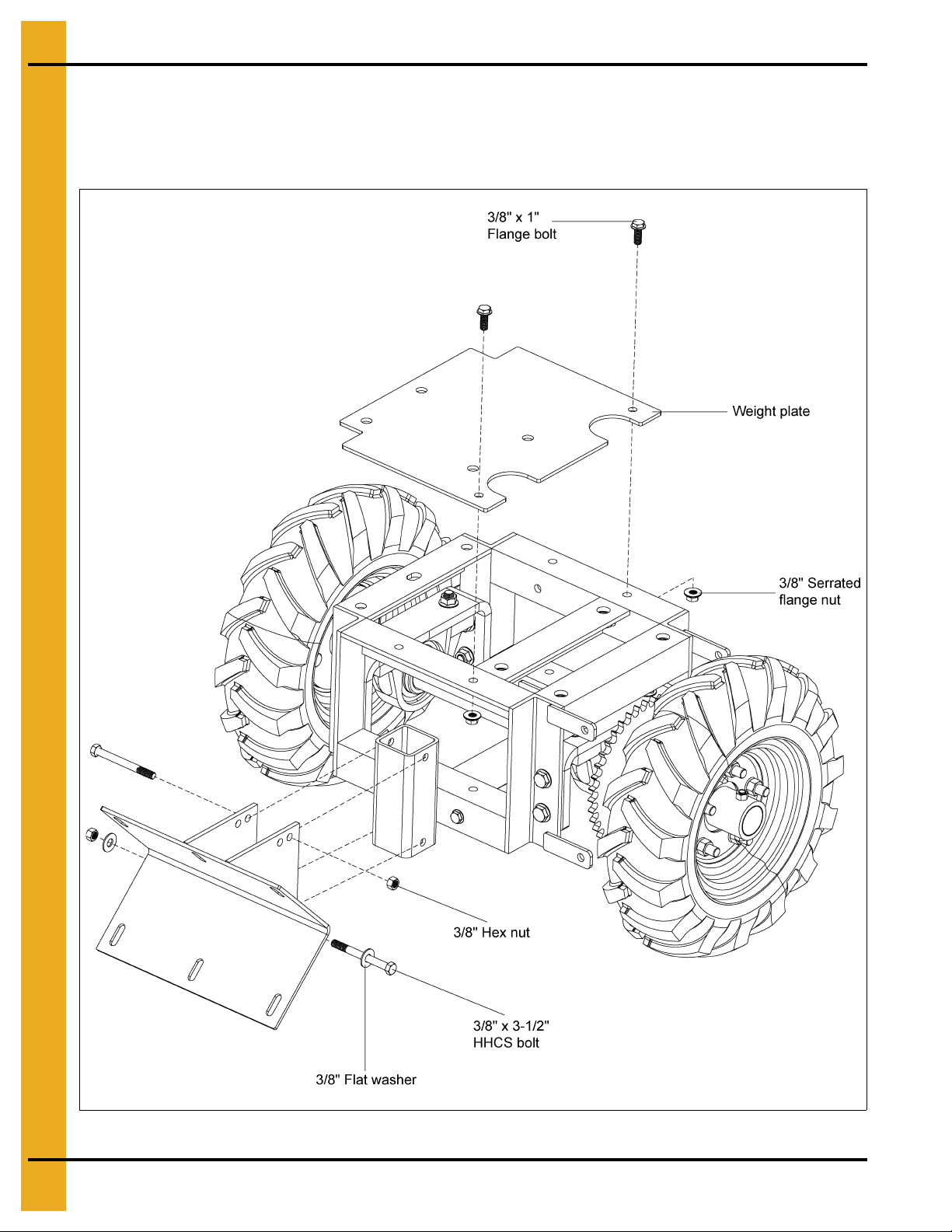
9. Bolt the shield bracket to the front of the tractor frame using two (2) 3/8"-16 x 3-1/2" hex head
cap screws, two (2) flat washers (only on the bottom slot of the bracket) and hex nuts.
10. Attach the weight plate to the tractor frame using two (2) 3/8"-16 x 1" flange bolts and serrated
flange nuts. (See Figure 4D.)
Figure 4D
14 PNEG-1597 Sweep Tractor and Control Panel Assembly Instructions
Page 15
4. Assembly
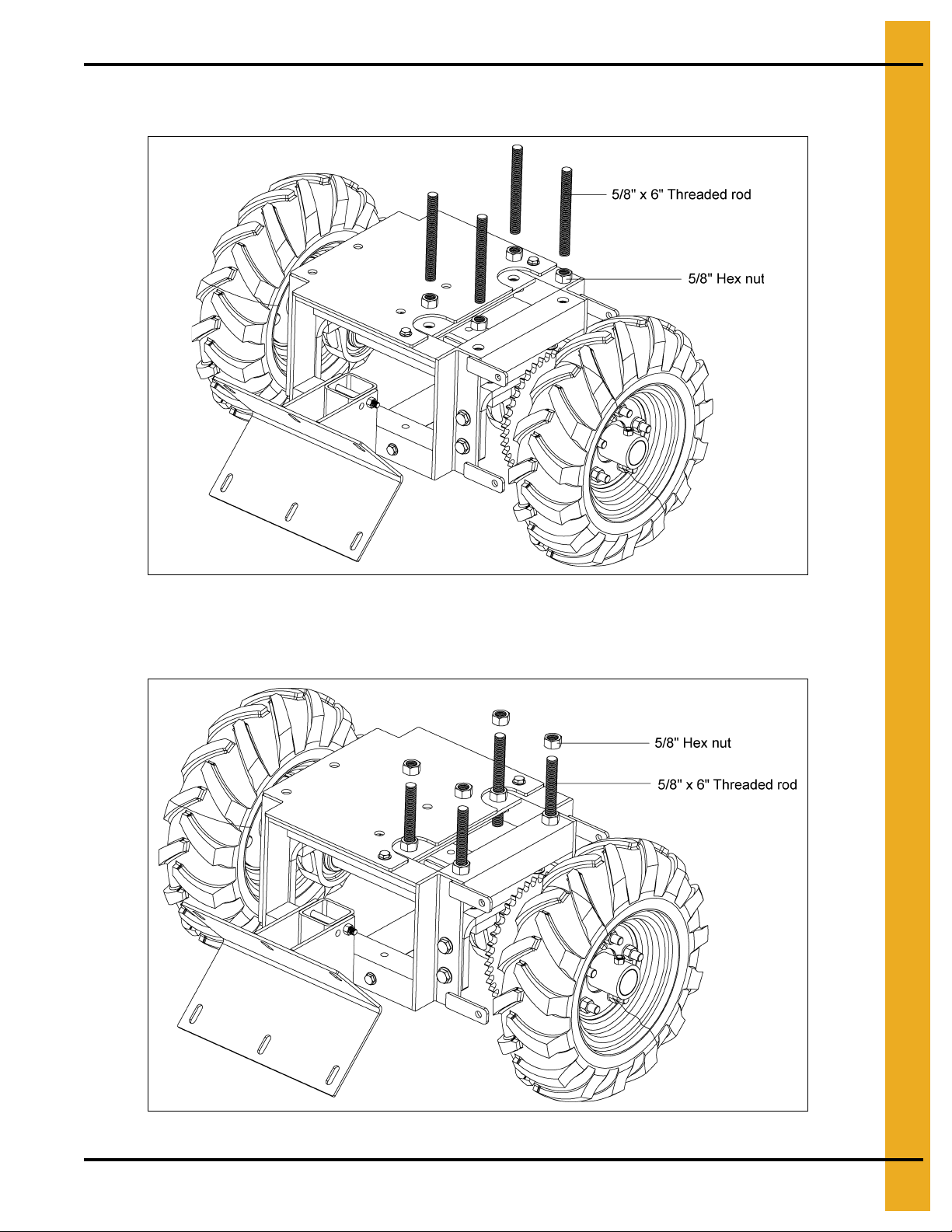
11. Bolt the four (4) 5/8"-11 x 6" threaded rods to the tractor frame using one 5/8"-11 hex nut for
each rod. (See Figure 4E.)
Figure 4E
12. Place one 5/8"-11 hex nut onto each rod in a temporary position. These will hold the motor plate in
place. (See Figure 4F.)
Figure 4F
PNEG-1597 Sweep Tractor and Control Panel Assembly Instructions 15
Page 16

4. Assembly
13. Mount the drive assembly to the gearbox plate using four (4) 3/8"-16 x 1" flange bolts. Place the
gearbox plate and motor assembly over the threaded rods, resting on the hex nuts. (See Figure 4G.)
Figure 4G
16 PNEG-1597 Sweep Tractor and Control Panel Assembly Instructions
Page 17

4. Assembly
14. Mount the gearbox plate and motor assembly to the 5/8"-11 x 6" threaded rod installed to the tractor
frame using four (4) 5/8"-11 hex nuts.
15. Attach the weight stand to the weight plate and tractor frame with four (4) 1/2"-13 x 1-1/4" flange bolts
and serrated flange nuts. (See Figure 4H.)
Figure 4H
PNEG-1597 Sweep Tractor and Control Panel Assembly Instructions 17
Page 18

4. Assembly
16. Assemble the 13 tooth sprocket to the motor shaft using a 1/4" square x 1" key.
17. Install the roller chain around both sprockets. Adjust the position each sprocket or the tractor axle
(if necessary) to correctly align the chain.
18. Tighten all the sprocket set screws.
19. Tension the roller chain as required by adjusting the nuts on the 5/8"-11 x 6" threaded rods.
(See Figure 4I.)
NOTE: Tighten both pillow block bearing lock collars at this time.
Figure 4I
18 PNEG-1597 Sweep Tractor and Control Panel Assembly Instructions
Page 19

4. Assembly
20. Install the top chain guard assembly to the tractor frame using four (4) 3/8"-16 x 1" flange bolts.
Slide the bottom chain guard assembly through the slot on the top chain guard and secure it with a
3/8"-16 x 3/4" flange bolt. (See Figure 4J.)
Figure 4J
PNEG-1597 Sweep Tractor and Control Panel Assembly Instructions 19
Page 20

4. Assembly
21. Mount the weights to the weight stand using one 5/8"-11 x 8-1/2" threaded rod and three (3) flange
nuts and one flat washer. (See Figure 4K.)
NOTE: Install the weights against the left hand of the weig ht stand so the weight is in the middle of
the tractor assembly. The weight stand can be reversed so that the weights hang over the
front of the frame, if necessary. Adjust the weights to the inside of the frame to center the
weight on the frame when the weight stand is reversed as described above.
Figure 4K
20 PNEG-1597 Sweep Tractor and Control Panel Assembly Instructions
Page 21

4. Assembly
End Wheel Assembly
NOTE: If installing sweep tractor to an existing sweep, the current end wheel components must
be removed.
1. Connect the stub shaft into the sweep flight using a 5/8"-11 x 4" hex head cap screw and
5/8" stover nut.
2. Install the bearing stand assembly onto the stub shaft and bolt it to the sweep shield using two (2)
3/8" x 3" carriage bolts, flat washers and nylock nuts.
3. Install the end wheel and collar onto the end of the stub shaft. Pin the collar in place with a
1/2" x 3-1/2" hex head cap screw and prevailing torque lock nut. (See Figure 4L.)
Figure 4L End Wheel Assembly
PNEG-1597 Sweep Tractor and Control Panel Assembly Instructions 21
Page 22

4. Assembly
All electrical wiring shall be installed by a qualified electrician and must meet the
standards set by the National Electric Code and all local and state codes.
Sweep Tractor to Shield Assembly
1. Position sweep tractor against the sweep shield approximately 3' from the end wheel.
2. Use the bracket on the sweep tractor to mark the location where the holes need to be drilled into the
sweep shield.
3. The bolts that attach the sweep bracket to the tractor frame may need to be a djusted so t hat he ight
and angle of the sweep back shield and the shield bracket are matched.
4. After marking the hole locations, drill six (6) 7/16" holes and attach the sweep tractor to the back
shield using six (6) 3/8" x 1" hex head cap screws, flat washers and nylock nuts.
5. Install electric wiring for motor and controls. (See Figure 4M.)
CAUTION
Figure 4M Sweep Tractor to Shield Assembly
22 PNEG-1597 Sweep Tractor and Control Panel Assembly Instructions
Page 23

5. Operation
Programming
Control Panel Calibration
Observe the tractor drive motor nameplate and the auger drive motor nameplate.
Record the full load amp (FLA) value for the specific voltage on each motor.
Auger drive motor full load amps: ____
Tractor drive motor full load amps: ____
Unlock and open the control panel.
Adjust the FLA dial screw on the tractor drive motor contactor (M2) and the auger drive motor
contactor (M1) so that the indicator arrowhead is set slightly higher than the full load amp value listed
on the nameplates.
Tractor drive motor contactor (M1) FLA adjustment dial: ____
Auger drive motor (M2) FLA adjustment dial value: ____
Close and lock the control panel.
Initial Display Setup
NOTE: If no keys are activated for 2 minutes, the display returns to the default state without saving any
configuration changes. At each value, after 5 seconds of inactivity, a description of the current
state will scroll across the display.
NOTE: Pressing and hold OK will return to the previou s menu or return to the default state without saving
the changed values or parameters.
Press OK on the display unit.
(IN) should be displayed on the unit.
Press or on the display unit until (CURR) is shown (not VOLT, POTM or TEMP).
Press OK.
(RANG) should be displayed on the unit.
Press or on the display unit until 4-20 is shown (not 0-20).
Press OK.
(DEC.P) should be displayed on the unit.
Press or on the display unit until 11.11 is shown (not 1111, 111.1, 1.111 or .1111).
Press OK.
PNEG-1597 Sweep Tractor and Control Panel Assembly Instructions 23
Page 24

5. Operation
(DI.LO) should be displayed on the unit.
Press or on the display unit until 0 is shown.
Press OK.
(DI.HI) should be displayed on the unit.
The DI.HI value will match the amperage range selection switch value on the current transducer
(30, 60 or 90). Refer part # AS-0736 on Page 39.
Press or on the display unit until the correct value is shown.
Press OK repeatedly until “-----” is displayed. This indicates the programming described above has
been saved.
Make sure no individual is inside the bin.
Make sure the sweep will not contact any obstruction and cause damage.
Have an employee observe the sweep from outside the bin, through the open door.
Have another employee operate the control panel.
Switch the Run Mode switch so that Manual is selected (not Auto).
Switch the Manual Mode switch to idle (not reverse or forward).
Press the Start button on the control panel.
NOTE: If any dama ge is observed or there is abnormal operation of the sweep, shut it down immediately.
There are three (3) ways to accomplish this. 1) Remove the pressure on the safety foot switch.
2) Press the Stop button on the control panel. 3) Press in on the Enable/Disable button so that it
collapses appropriately. Switch the disconnect switch on the panel to OFF (not ON). Lock out the
panel before entering the bin to service the sweep.
Observe the no load amps (NLA) displayed on the meter on the front of the panel.
Auger drive motor no load amps: ____
The tractor motor operation (forward and stop) in automatic is dictated by the amp reading on the auger
drive motor.
The tractor drive motor is meant to shut off (idle) when the Auger Drive Motor reaches 90% of the
nameplate FLA.
90% of full load amps: ____
The tractor motor is meant to reactivate (forward) when the auger drive motor reaches 110% of the no load
amps (amperage observed when the auger flight turns freely in absence of grain).
110% of no load amps: ____
24 PNEG-1597 Sweep Tractor and Control Panel Assembly Instructions
Page 25

5. Operation
Final Display Setup
NOTE: If no keys are activated for 2 minutes, the display returns to the default state without saving any
configuration changes. At each value, after 5 seconds of inactivity, a description of the current
state will scroll across the display.
Press OK repeatedly until RELU is displayed on the unit.
Press or on the display unit until DISP is shown (not PERC).
Press OK.
REL1 should be displayed on the unit.
Press or on the display unit until SET is shown (not SKIP or OFF).
Press OK.
SETP should be displayed on the unit.
Press or on the display unit the 90% of FLA value is shown.
Press OK.
ACT1 should be displayed on the unit.
Press or on the display unit until INCR is shown (not DECR).
Press OK.
HYS1 should be displayed on the unit.
For this control panel hysteresis (HYS1) is measured as the different between 90% of full load amps and
110% of no load amps.
90% of full load amps: ____ minus 110% of no load amps: ____
Press or on the display unit until the correct value is shown.
Press OK.
ERR1 should be displayed on the unit.
Press or on the display unit until DEAC is shown (not HOLD, ACTI or NONE).
Press OK.
ON.DE should be displayed on the unit.
Press or on the display unit until 0 is shown.
Press OK.
PNEG-1597 Sweep Tractor and Control Panel Assembly Instructions 25
Page 26

5. Operation
OF.DE should be displayed on the unit.
Press or o the display unit until 20 is shown.
Press OK.
REL2 should be displayed on the unit.
Press or on the display unit until OFF is shown (not SET or SKIP).
Press OK.
E.PAS should be displayed on the unit.
Press or on the display unit until NO is shown.
Press OK.
This function will allow the values that were entered to be locked.
NOTE: Using a password will stop access to the menu and parameters. There are two (2) levels of
password protection. Passwords between 0000 and 4999 allow access to the fast set point
adjustment and relay test. (Using this password stops access to all other parts of the menu.)
Passwords between 5000 and 9999 stop access to all parts of the menu, fast set point adjustment
and relay test. (Current set point is still shown.) By using the master password 2008, all
configuration menus are available.
If you select NO, press OK.
If you select YES, N.PAS will be displayed. Press or on the display unit until your password is shown.
Press OK. Document this password.
The password will be necessary if there needs to be changes to many of the configuration values.
26 PNEG-1597 Sweep Tractor and Control Panel Assembly Instructions
Page 27

NOTES
PNEG-1597 Sweep Tractor and Control Panel Assembly Instructions 27
Page 28

6. Control Panel Diagrams
Sweep Tractor Control Box Definitions
Commercial Sweep Control Panel
28 PNEG-1597 Sweep Tractor and Control Panel Assembly Instructions
Page 29

6. Control Panel Diagrams
Schematic - Control Panel GCS Sweeps 230V 3 HP (GCSTP2-03)
PNEG-1597 Sweep Tractor and Control Panel Assembly Instructions 29
Page 30

6. Control Panel Diagrams
Schematic - Control Panel GCS Sweeps 230V 5 HP (GCSTP2-05)
30 PNEG-1597 Sweep Tractor and Control Panel Assembly Instructions
Page 31

6. Control Panel Diagrams
Schematic - Control Panel GCS Sweeps 230V 7.5 HP (GCSTP2-75)
PNEG-1597 Sweep Tractor and Control Panel Assembly Instructions 31
Page 32

6. Control Panel Diagrams
Schematic - Control Panel GCS Sweeps 230V 10 HP (GCSTP2-10)
32 PNEG-1597 Sweep Tractor and Control Panel Assembly Instructions
Page 33

6. Control Panel Diagrams
Schematic - Control Panel GCS Sweeps 460V 3 HP (GCSTP4-03)
PNEG-1597 Sweep Tractor and Control Panel Assembly Instructions 33
Page 34

6. Control Panel Diagrams
Schematic - Control Panel GCS Sweeps 460V 5 HP (GCSTP4-05)
34 PNEG-1597 Sweep Tractor and Control Panel Assembly Instructions
Page 35

6. Control Panel Diagrams
Schematic - Control Panel GCS Sweeps 460V 7.5 HP (GCSTP4-75)
PNEG-1597 Sweep Tractor and Control Panel Assembly Instructions 35
Page 36

6. Control Panel Diagrams
Schematic - Control Panel GCS Sweeps 460V 10 HP (GCSTP4-10)
36 PNEG-1597 Sweep Tractor and Control Panel Assembly Instructions
Page 37

6. Control Panel Diagrams
Schematic - Control Panel GCS Sweeps 460V 15 HP (GCSTP4-15)
PNEG-1597 Sweep Tractor and Control Panel Assembly Instructions 37
Page 38

6. Control Panel Diagrams
Standa rd Control Panel Assembly 230V 3 Phase
38 PNEG-1597 Sweep Tractor and Control Panel Assembly Instructions
Page 39

6. Control Panel Diagrams
Standard Control Panel Assembly 230V 3 Phase Parts List
Qty
Ref # Part # Description
1 C-8711 Transformer 1 1 1 1
2GC20176Ground Bar Kit 1111
3 AS-0736 Current Transducer 1 1 1 1
4 GC20170 Manual Starter Terminal Block 2222
5 GC20184 Auger Motor Starter and Protector 1 1 1 1
6 GC20186 Auger Motor Starter and Protector 1 - - 6 GC20187 Auger Motor Starter and Protector - 1 - 6 GC20188 Auger Motor Starter and Protector - - 1 6 GC20189 Auger Motor Starter and Protector - - - 1
7 056-1942-4 Auger Relay 1 - - 7 056-1949-9 Auger Relay - 1 - 7 056-1969-7 Auger Relay - - 1 -
GCSTP2-03 GCSTP2-05 GCSTP2-75 GCSTP2-10
3 HP 5 HP 7.5 HP 10 HP
7 056-1941-6 Auger Relay - - - 1
8GC20168Reverse Contactor 1111
9 GC20169 Starter Cable Busbar 1 1 1 1
PNEG-1597 Sweep Tractor and Control Panel Assembly Instructions 39
Page 40

6. Control Panel Diagrams
Standa rd Control Panel Assembly 460V 3 Phase
40 PNEG-1597 Sweep Tractor and Control Panel Assembly Instructions
Page 41

6. Control Panel Diagrams
Standard Control Panel Assembly 460V 3 Phase Parts List
Qty
Ref # Part # Description
1 C-871 1 Transformer 1 1 1 1 1
2 GC20176 Ground Bar Kit 1 1 1 1 1
3 AS-0736 Current Transducer 1 1 1 1 1
4 GC20170 Manual Starter Terminal Block 2 2 2 2 2
5 GC20185 Motor Starter and Protector 1 1 1 1 1
6 GC20190 Auger Motor Starter and Protector 1 - - - 6 D03-0964 Auger Motor Starte r and Protector - 1 - - 6 GC20186 Auger Motor Starter and Protector - - 1 - 6 GC20187 Au ger Motor Starter and Protector - - - 1 6 GC20188 Auger Motor Starter and Protector - - - - 1
7 056-1948-1 Auger Relay 1 1 - - 7 056-1942-4 Auger Relay - - 1 - -
GCSTP4-03 GCSTP4-05 GCSTP4-75 GCSTP4-10 GCSTP4-15
3 HP 5 HP 7.5 HP 10 HP 15 HP
7 056-1969-7 Auger Relay - - - 1 1
8 GC20168 Reverse Contactor 1 1 1 1 1
9 GC20169 Starter Cable Busbar 1 1 1 1 1
PNEG-1597 Sweep Tractor and Control Panel Assembly Instructions 41
Page 42

NOTES
42 PNEG-1597 Sweep Tractor and Control Panel Assembly Instructions
Page 43

1. Sweep Tractor Parts
2. Chain Guard Assembly
3. Drive Motor Assembly
4. Bearing Stand Assembly
7. Parts List
PNEG-1597 Sweep Tractor and Control Panel Assembly Instructions 43
Page 44

7. Parts List
Sweep Tractor Parts
44 PNEG-1597 Sweep Tractor and Control Panel Assembly Instructions
Page 45

7. Parts List
Sweep Tractor Parts List
Ref # Part # Description Ref # Part # Description
1 GK7714 Tractor Frame 30 GK7725 5/8"-11 x 8-1/2" Threaded Rod
2 GK7716 Bearing Mounting Bracket 31 S-9259 5/8"-11 Serrated Flange Nut Zinc
3 S-9062
4 S-8506 1/2"-13 Serrated Flange Nut Zinc 33 S-858 5/8" Flat Washer USS Zinc
5 017-1486-4 Bearing: 1-5/8" Bore Pillow Block
6 S-2120 1/2" Flat Washer SAE Zinc
7 S-781 1 1/2"-13 x 2" HHCS Bolt Zinc Grade 5 GK4975
8 GK7724
9 S-9179 3/8" Square x 1-3/4" Key 36 S-248 3/8" Flat Washer YDP
10 GK7715 Tractor Axle 37 S-7469 3/8"-16 x 1" HHCS Bolt Zinc Grade 5
11 GK7718 Wheel Hub 38 S-7383 3/8"-16 Nylock Nut Zinc Grade 5
12 S-6762 3/8"-16 x 2-1/2" Hex Bolt Zinc Grade 5
13 S-8251 3/8"-16 Stover Nut Zinc Grade C GK80166 Stub Shaft - GCS8-10
14 S-8260 Nylock Nut 1/2"-13 ZN Grade 5 GK4952 Stub Shaft - GCS10-12 and GCS12-14
15 GK7748
16 GK80116 Strut Bracket GK4951 Stub Collar - GCS10-12 and GCS12-14
17 S-9065 3/8"-16 x 1" Flange Bolt Zinc Grade 5
18 S-968
19 GK80115 Weight Support Plate GK6457 End Wheel with Bearing - GCS10-12
20 GC03552 5/8"-11 x 6" Threaded Rod GK4954 End Wheel with Bearing - GCS12-14
21 S-4110 5/8"-11 Hex Nut Zinc Grade 5
22 GK7883 Roller Chain, #50, 61 Pitch GK1954 Bea r ing Stand Assembly - GCS8-10
23 D32-0015 Roller Chain Connecting Link, #50 GK2047 Bearing Stand Assembly - GCS10-12
24 GK4978
25 S-9168 1/4" Square x 1" Key
GK4985
GK7828
GK5481
26
GK6387
GK7720
GK6827
27 GK7719 Drive Assembly Plate
28 GK80029 Chain Guard Assembly
29 GK80117 Weight Bracket 47 S-8055 3/8"-16 x 3" Carriage Bolt Zinc Grade 5
1/2"-13 x 1-1/4" Flange Bolt Zinc
Grade 5
Sprocket, #50, 40 Tooth, 1-5/8" Bore,
Type B
Tire and Wheel: 4.80-8 5-Lug,
Foam Filled
3/8"-16 Wide Serrated Flange Nut Zinc
Grade 5
Sprocket, #50, 13 Tooth, 1-1/8" Bore,
Type B
Drive Motor Assembly - 1 PH, 60 Hz,
1 15/230V, TEFC
Drive Motor Assembly - 1 PH, 60 Hz,
115V/208V-230V, XPFC
Drive Motor Assembly - 3 PH, 60 Hz,
230V/460V, TEFC
Drive Motor Assembly - 3 PH, 60 Hz,
208V-230V/460V, XPFC
Drive Motor Assembly - 3 PH, 60 Hz,
575V, XPFC
Drive Motor Assembly - 3 PH, 50 Hz,
220V/380V/460V, TEFC
32 GK7717 Tractor Weight - 50 Lbs.
GK80172 Shield Bracket - GCS6-8
GK80173 Shield Bracket - GCS8-10
34
35 S-8989 3/8"-16 x 3-3/4" HHCS Bolt Zinc Grade 5
GK80165 Stub Shaft - GCS6-8
39
GK80163 Stub Collar - GCS6-8
40
GK80164 Stub Collar - GCS8-10
GK80161 End Wheel with Bearing - GCS6-8
GK80162 End Wheel with Bearing - GCS8-10
41
GK2107 Bearing Stand Assembly - GCS6-8
42
GK80084 Bearing Stand Assembly - GCS12-14
S-8314 1/2"-13 x 3-1/2" HHCS Bolt YDP Grade 8
43
S-7372
S-8315
44
S-8317 Stover Nut 7/16"-14 ZN Grade C - GCS6
S-7893 5/8"-11 x 4" HHCS Bolt YDP Grade 8
45
S-8316
S-8606 5/8"-11 Stover Nut Zinc Grade C
46
S-8317 Stover Nut 7/16"-14 ZN Grade C - GCS6
Shield Bracket - GCS10-12 and
GCS12-14
Bolt, HHCS 7/16"-14 x 2-1/2" ZN Grade 8
- GCS6
1/2"-13 Prevailing Torque Lock Nut Zinc
Grade C
Bolt, HHCS 7/16"-14 x 3 ZN YDP Grade 8
- GCS6
PNEG-1597 Sweep Tractor and Control Panel Assembly Instructions 45
Page 46

7. Parts List
Chain Guard Assembly
Chain Guard Assembly Parts List
Ref # Part # Description
1 GK7712 Chain Guard Top Assembly
2 GK7713 Chain Guard Bottom Assembly
3 S-9067 3/8"-16 x 3/4" Flange Bolt Zinc Grade 5
46 PNEG-1597 Sweep Tractor and Control Panel Assembly Instructions
Page 47

Drive Motor Assembly
7. Parts List
Drive Motor Assembly Parts List
Ref # Part # Description
1 GK4987 Worm Gear Reducer, 60:1, 56C, LO, S23
2 CFDL3504M Motor - 1/2 HP, 1 PH, 60 Hz, 1725 RPM, 115/230V, TEFC, 56C
2 FLX-4021-1PH Motor - 1/2 HP, 1 PH, 60 Hz, 1725 RPM, 115/208-230V, XPFC, 56C
2 FLX-3547 Motor - 1/2 HP, 3 PH, 60 Hz, 1725 RPM, 230/460V, TEFC, 56C
2 FLX-4021 Motor - 1/2 HP, 3 PH, 60 Hz, 1725 RPM, 208-230/460V, XPFC, 56C
2 012-3E-575XP Motor - 1/2 HP, 3 PH, 60 Hz, 1725 RPM, 575V, XPFC, 56C
2 002-1408-0 Motor - 1/2 HP, 3 PH, 50 Hz, 1725 RPM, 220/380/460V, TEFC, 56C
3 S-1054 3/8" Split Lock Washer Zinc
4 S-7469 3/8"-16 x 1" HHCS Bolt Zinc Grade 5
PNEG-1597 Sweep Tractor and Control Panel Assembly Instructions 47
Page 48

7. Parts List
Bearing Stand Assembly
Bearing Stand Assembly Parts List
Ref # Part # Description
1 GK1626 Bearing Stand - GCS8
1 GK1679 Bearing Stand - GCS10
1 GK2049 Bearing Stand - GCS12
1 GK2172 Bearing Stand - GCS14
2 GK1680 Bearing Stand Bearing Assembly - GCS8
2 GK1955 Bearing Stand Bearing Assembly - GCS10
2 GK2050 Bearing Stand Bearing Assembly - GCS12
2 GK2163 Bearing Stand Bearing Assembly - GCS14
3 S-7837 7/16"-14 x 1-1/2" HHCS Bolt Zinc Grade 5
4 S-8317 Stover Nut 7/16" -14 ZN Grade C
48 PNEG-1597 Sweep Tractor and Control Panel Assembly Instructions
Page 49

8. Warranty
9101239_1_CR_rev7.DOC (revised July 2009)
GSI Group, LLC Limited Warranty
The GSI Group, LLC (“GSI”) warrants products which it manufactures to be free of defects in materials and workmanship
under normal usage and conditions for a period of 12 months after sale to the original end-user or if a foreign sale,
14 months from arrival at port of discharge, whichever is earlier. The end-user’s sole remedy (and GSI’s only obligation)
is to repair or replace, at GSI’s option and expense, products that in GSI’s judgment, contain a material defect in materials
or workmanship. Expenses incurred by or on behalf of the end-user without prior written authorization from the GSI
Warranty Group shall be the sole responsibility of the end-user.
Warranty Extensions:
The Limited Warranty period is extended for the following products:
Product Warranty Period
Performer Series Direct Drive Fan Motor 3 Years
AP Fans and Flooring
Cumberland
Feeding/Watering
Systems
Grain Systems Grain Bin Structural Design 5 Years
Grain Systems
Farm Fans
Zimmerman
All Fiberglass Housings Lifetime
All Fiberglass Propellers Lifetime
Feeder System Pan Assemblies 5 Years **
Feed Tubes (1-3/4" and 2.00") 10 Years *
Centerless Augers 10 Years *
Watering Nipples 10 Years *
Portable and Tower Dryers 2 Years
Portable and Tower Dryer Frames and
Internal Infrastructure †
5 Years
* Warranty prorated from list price:
0 to 3 years - no cost to end-user
3 to 5 years - end-user pays 25%
5 to 7 years - end-user pays 50%
7 to 10 years - end-user pays 75%
** Warranty prorated from list price:
0 to 3 years - no cost to end-user
3 to 5 years - end-user pays 50%
† Motors, burner components
and moving parts not included.
Portable dryer screens included.
Tower dryer screens not included.
GSI further warrants that the portable and tower dryer frame and basket, excluding all auger and auger drive components,
shall be free from defects in materials for a period of time beginning on the twelfth (12
and continuing until the sixtieth (60
th
) month from the date of purchase (extended warranty period). During the extended
th
) month from the date of purchase
warranty period, GSI will replace the frame or basket components that prove to be defective under normal conditions
of use without charge, excluding the labor, transportation, and/or shipping costs incurred in the performance of this
extended warranty.
Conditions and Limitations:
THERE ARE NO WARRANTIES THAT EXTEND BEYOND THE LIMITED WARRANTY DESCRIPTION SET FORTH
ABOVE. SPECIFICALLY, GSI MAKES NO FURTHER WARRANTY OF ANY KIND, EXPRESS OR IMPLIED,
INCLUDING, WITHOUT LIMITATION, WARRANTIES OF MERCHANTABILITY OR FITNESS FOR A PARTICULAR
PURPOSE OR USE IN CONNECTION WITH: (I) PRODUCT MANUFACTURED OR SOLD BY GSI OR (II) ANY ADVICE,
INSTRUCTION, RECOMMENDATION OR SUGGESTION PROVIDED BY AN AGENT, REPRESENTA TIVE OR
EMPLOYEE OF GSI REGARDING OR RELATED TO THE CONFIGURATION, INSTALLATION, LAYOUT, SUITABILITY
FOR A PARTICULAR PURPOSE, OR DESIGN OF SUCH PRODUCTS.
GSI shall not be liable for any direct, indirect, incidental or consequential damages, including, without limitation, loss of
anticipated profits or benefits. The sole and exclusive remedy is set forth in the Limited Warranty, which shall not exceed
the amount paid for the product purchased. This warranty is not transferable and applies only to the original end-user. GSI
shall have no obligation or responsibility for any representations or warranties made by or on behalf of any dealer, agent
or distributor.
GSI assumes no responsibility for claims resulting from construction defects or unauthorized modifications to products
which it manufactured. Modifications to products not specifically delineated in the manual accompanying the equipment at
initial sale will void the Limited Warranty.
This Limited Warranty shall not extend to products or parts which have been damaged by negligent use, misuse, alteration,
accident or which have been improperly/inadequately maintained. This Limited Warranty extends solely to products
manufactured by GSI.
Prior to installation, the end-user has the responsibility to comply with federal, state and local codes which apply to the
location and installation of products manufactured or sold by GSI.
PNEG-1597 Sweep Tractor and Control Panel Assembly Instructions 49
Page 50

This equipment shall be installed in accordance with
the current installation codes and applicable
regulations, which should be carefully followed in all
cases. Authorities having jurisdiction should be
consulted before installations are made.
Copyright © 2013 by GSI Group
Printed in the USA
GSI Group
1004 E. Illinois St.
Assumption, IL 62510-0020
Phone: 1-217-226-4421
Fax: 1-217-226-4420
www.gsiag.com
CN-303144
 Loading...