

Page 1

Instructions
PNEG-1594
Omron H5CR Timer
1004 East Illinois Street • Assumption, IL 62510 • 1-217-226-4421
The CTR-004A Cycle Timer Replacement Kit is designed as a service replacement package for replacing
the Omron H5CR Cycle Timers, part # 415-3213-6, used on the CF/AB and CF/SA series dryers from
1997 through 2005. This kit replaces all three (3) cycle timers with the new style H5CX Omron Brand
Timer. It is not designed to be used on dryers older than 1997.
The CTR 004A timers function similar to earlier timers, but because of the new timer uses LED technology,
the timers will have to be rewired. Once it is rewired, you will be able to view and/or change the timer
settings. Please read the following information for installing and operating the new timers. Retain this
bullet-in with the operation manual for future circuit diagram and parts reference.
These instructions will cover CFAB 150-320 models made in 97-4/99 and 5/99-2005. All CFSA
models will require the addition of three (3) relays (included in this kit) and the circuit rewired with the
supplied instructions.
CFAB 150-320 made from 97-4/99 will not have written wiring instructions due to the lack of resources
concerning this series model. To determine if you have this series look for two (2) relays labeled 4CR and
5CR. If you have both of these relays you have the later circuit made after 4/99. If you do not, use the
wiring schematics that have been provided in Figure 5 on Page 10 and Figure 6 on Page 11. The BOLD
lines all schematics indicate which parts of the circuit have been affected and need to be changed.
Replacement Kit Instructions
CFAB 400-600 model dryers can use these timers directly with a terminal for terminal exchange of timers.
However, the times on the timers are unable to be adjusted until they are activated by the previous timer.
(For instance, the Cool Timer can not be adjusted until the Dry Timer expires; likewise with the Unload
Timer can not be adjusted until the Cool Timer expires.)
NOTE: CFAB 400-600 only: The new timer does not contain a terminal 10, so discard the jumper wire
normally located between terminals 8 and 10. The schematic in the operation manuals
(CFABL-01-2 and CFABL-02-2) can still be used to troubleshoot this circuit.
Timer Installation
1. Shut off the main power supply and turn dryer circuit breakers OFF.
2. Open the ASC dead front and disconnect wiring from the old cycle timers.
3. Remove the old timers from the dead front one at a time, making note of which wire numbers are
installed to each of the terminals.
4. Install the three (3) new H5CX timers using the white plastic panel mounting adaptor to lock the
timers to the dead front panel.
5. Mark and drill 2-13/64" holes in the front panel to mount the supplied din rail.
6. Attach the relays onto the din rail.
7. Mark the relays with the supplied labels. Place the UTR label on the larger 3PDT relay and the DTR,
CTR to the two (2) smaller relays.
8. Rewire the cycle timer circuit as indicated using the appropriate wiring diagram and step by step
instructions at supplied in this bullet-in.
Date: 07-29-13 PNEG-1594
Printed in the U.S.A.
Copyright © 2013 by GSI Group
www.gsiag.com
Page 1 of 11
CN-307138
Page 2
Omron H5CR Timer Replacement Kit Instructions
Timer Testing
1. For testing purposes only, set each of the three (3) cycle timers to the 3 minutes range and adjust
timers to approximately 2 minutes.
2. Turn ON the dryer’s main power and dryer circuit breakers.
3. Start the dryer control circuit; turn the Mode Selector switch to AB or SA and the Electronic Moisture
Control switch (CF/AB) or the MC Selector switch (CF/SA) to OFF. Also turn the Unload switch to
AUTO, the CF/AB Fan switch to ON, the CF/AB Burner switch to AUTO; or the CF/SA Bottom Fan
switch to AUTO and the CF/SA Bottom Burner switch to AUTO.
4. Run the dryer through a complete HEATING, COOLING and UNLOAD cycle, being sure that the
cycles are completed as described in your operator’s manual.
5. MC HOLD CHECK: Restart the dryer and turn the Electronic Moisture Control switch (CF/AB) to ON
or the MC Selector switch (CF/SA) to ON. Also set the MC temp dial to its maximum set point. The
HEAT timer should complete its drying cycle, the MC hold light should come ON and heating should
continue. Decrease the MC set point until the MC hold light turns OFF. The heater should turn OFF
and the cooling cycle begins. Adjust the MC set point back up. The cooling cycle should continue.
6. UNLOAD AUGER SWITCH CHECK: Turn the Unload Auger switch to OFF. When the cooling cycle
is complete, the dryer will hold in the cooling mode until the Unload Auger switch is turned to AUTO
to begin the Unload cycle.
7. CONTINUOUS FLOW CHECK: Turn the Mode switch to Continuous Flow (CF/AB) or CF (CF/SA).
Also turn the Unload Auger switch to AUTO and observe that the unload auger and meter rolls are
operating and that the timers are not timing.
8. Reset the timers to the appropriate settings and ranges as recommended by the CYCLE TIME
CHARTS. (The times listed match those in the operator’s manual, except they are also listed with
decimal hours for convenience.)
Cycle Timer Parts List
Part # Description Qty
415-3233-0 H5CX Timer Programmed 3
TD-100282 SPDT 110VAC Relay 2
TD-100283 SPDT Relay Base 2
HF-7203 3PDT 110VAC Relay 1
7097555 3PDT Relay Base 1
406-2126-0 4" Din Rail Mount 1
S-8984 Screw, TCSF #10-32 x 5/8" RHP ZN 2
S-4334 Hex Nut #10-32 ZN Grade 2 2
PNEG-1594 Installation Instructions 1
DWL-CTR-004A Wire Label Set for Kit 1
18 Gauge White Wire 2
18 Gauge Red Wire 3
Page 2 of 11 PNEG-1594
Page 3
Omron H5CR Timer Replacement Kit Instructions
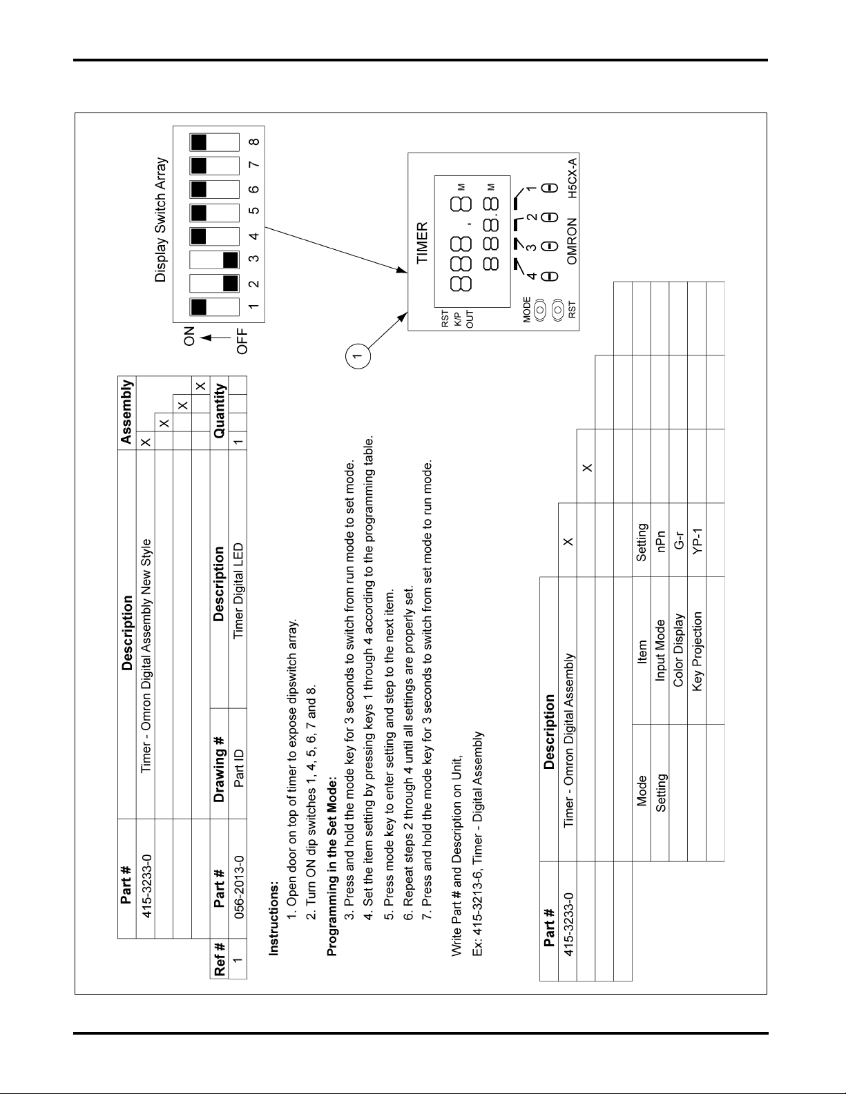
H5CX Programming Information
Figure 1 H5CX Programming Information
PNEG-1594 Page 3 of 11
Page 4
Omron H5CR Timer Replacement Kit Instructions
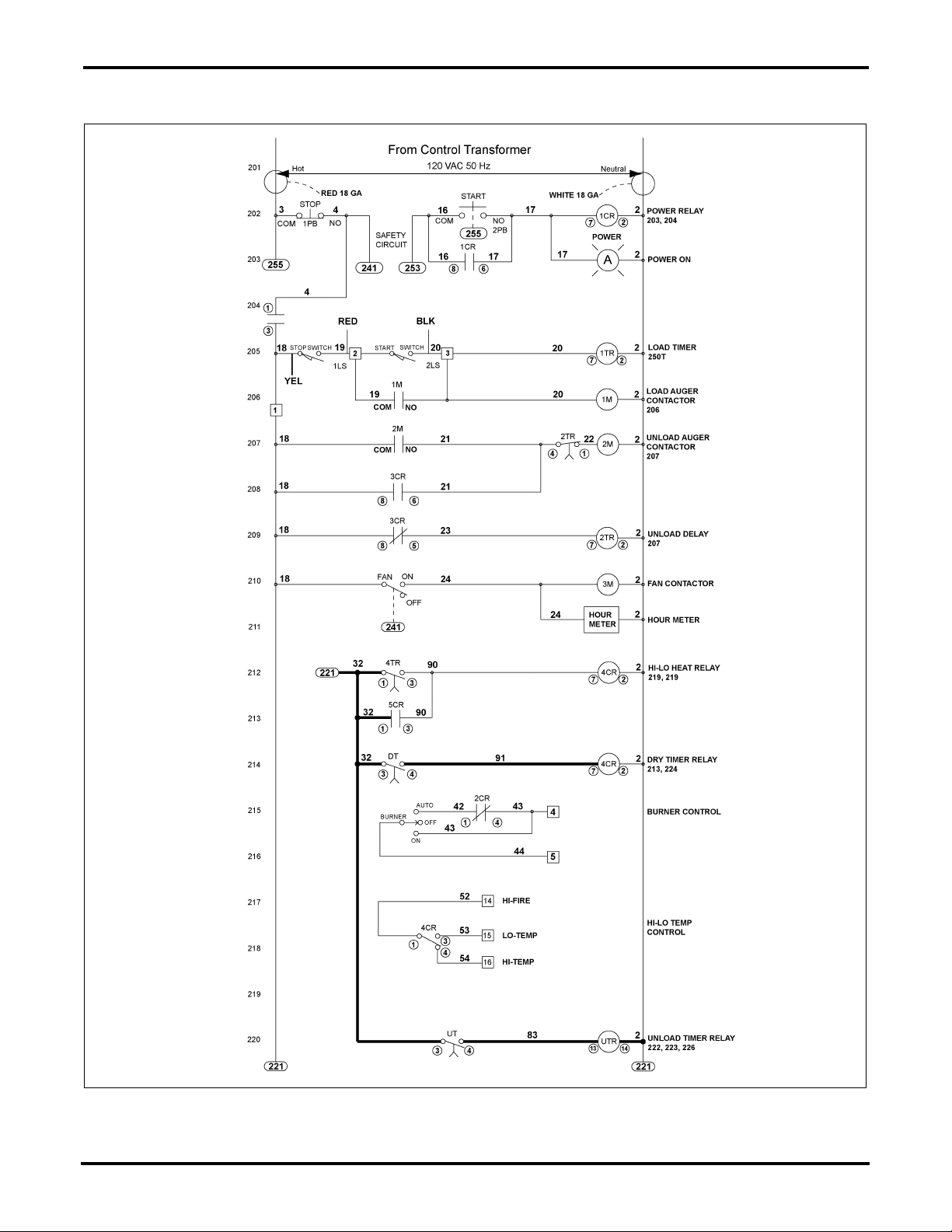
CFAB 150-320 Control Circuit 1 of 2
Figure 2 CFAB 150-320 Control Circuit 1 of 2
NOTE: Bold line indicates portion of circuit changed by Omron Timers.
Page 4 of 11 PNEG-1594
Page 5

Omron H5CR Timer Replacement Kit Instructions
CFAB 150-320 Control Circuit 2 of 2
Figure 3 CFAB 150-320 Control Circuit 2 of 2
NOTE: Bold line indicates portion of circuit changed by Omron Timers.
PNEG-1594 Page 5 of 11
Page 6

Omron H5CR Timer Replacement Kit Instructions
CFAB 150-320 Wiring Instructions
NOTE:
These wiring instructions are only good for models built after 4/99 and shown in
Figure 3 on Page 5
and
labeled pre-99 in
1. Install each new timer one at a time. Make note of what wire numbers are on each terminal of the old
H5CR timers. Then when you install the new H5CX timers, replace the wires back onto the same
numbered terminal they were on with the old timers. We will move these later but it is important that
we know where they are so there is less confusion on the rewiring of this circuit. (NOTE: There is no
terminal 10 on the new H5CX timers, so the jumper between 8 and 10 on all timers can be safely
removed and discarded.)
2. Locate the wire labeled 35 between Unload Timer terminal 1 and Cool Timer terminal 4. Disconnect
the wire from the Unload Timer terminal 1 and move it to the CTR relay terminal 13. (NOTE: If the
wire is not long enough, replace it with a longer wire.)
3. Remove the wire labeled 80 on Dry Timer terminal 6 and Unload Timer terminal 3. Discard the wire.
4. Locate the wire labeled 80 on the Unload Timer terminal 3 to the Reset switch and relocate the wire
from Unload Timer terminal 3 to the Unload Timer terminal 1. Re-label both ends of this wire as
wire 32.
5. Add a jumper between Unload Timer terminal 1 and Unload Timer terminal 3. Label this wire as
wire 32.
6. Locate the remaining jumper wire labeled 80 on the Dry Timer between terminals 6 and 8, remove
the wire label 80 sticker on this jumper and discard. Leave the jumper between 6 and 8 on the
Dry Timer.
Figure 5 on Page 10
. If you have the older version, you will need to refer to the wiring schematic
and
Figure 6 on Page 11
.
Figure 2 on Page 4
7. Remove the jumper labeled 81 on the Cool Timer located between terminals 6 and 8. Discard
this jumper.
8. Remove the jumper labeled 82 on the Unload Timer located between terminals 6 and 8. Discard
this jumper.
9. Remove the wire labeled 83 between Dry Timer terminal 7 and Cool Timer terminal 7. Discard
this wire.
10. Remove the wire labeled 83 between Cool Timer terminal 7 and Unload Timer terminal 7.
Discard this wire.
11. Locate the wire labeled 83 between Unload Timer terminal 7 and Unload Timer terminal 4.
Discard this wire. Leave the other 83 wire on the Unload Timer terminal 4.
12. Locate the wire labeled 33 on the Cool Timer terminal 1 and attach it to terminal 13 of the DTR relay.
(If the wire is not long enough, replace the wire with a longer piece between DTR terminal 13 and
5CR terminal 8.)
13. Add a wire labeled 83 from Unload Timer terminal 4 to UTR terminal 13.
14. Add a wire labeled 32 between Dry Timer terminal 3 and Cool Timer terminal 1. (NOTE: This will
place three (3) wires labeled 32 on terminal 3 of the Dryer Timer.)
15. Add a wire labeled 32 between Cool Timer terminal 1 and Unload Timer terminal 3.
16. Add a wire labeled 85 between Cool Timer terminal 8 and DTR terminal 5.
Page 6 of 11 PNEG-1594
Page 7

Omron H5CR Timer Replacement Kit Instructions
CFAB 150-320 Wiring Instructions (Continued)
17. Add a wire labeled 84 between Cool Timer terminal 6 and DTR terminal 9.
18. Add a wire labeled 84 between DTR terminal 9 and UTR terminal 12.
19. Add a wire labeled 86 between Unload Timer terminal 6 and CTR terminal 9.
20. Add a wire labeled 86 between CTR terminal 9 and UTR terminal 10.
21. Add a wire labeled 29 between UTR terminal 9 and Dry Timer terminal 6.
22. Add a wire labeled 87 between Unload Timer terminal 8 and CTR terminal 5.
23. Add a wire labeled 80 between UTR terminal 5 and Dry Timer terminal 7.
24. Add a wire labeled 81 between UTR terminal 8 and Cool Timer terminal 7.
25. Add a wire labeled 82 between UTR terminal 6 and Unload Timer terminal 7.
26. Connect a white wire (neutral) to any AC neutral wire connection (white wire that is labeled 2) and
connect the other end of it to UTR terminal 14.
27. Add a wire labeled 2 between UTR terminal 14 and CTR terminal 14.
28. Add a wire labeled 2 between CTR terminal 14 and DTR terminal 14.
PNEG-1594 Page 7 of 11
Page 8

Omron H5CR Timer Replacement Kit Instructions
CFSA Control Circuit
Figure 4 CFSA Control Circuit
NOTE: Bold line indicates portion of circuit changed by Omron Timers.
Page 8 of 11 PNEG-1594
Page 9

Omron H5CR Timer Replacement Kit Instructions
CFSA Wiring Instructions
1. Install each new timer one at a time. Make note of what wire numbers are on each terminal of the
old H5CR timers. Then when you install the new H5CX timers, replace the wires back onto the same
numbered terminal they were on with the old timers. We will move these later but it is important that
we know where they are so there is less confusion on the rewiring of this circuit. (NOTE: There is
no terminal 10 on the new H5CX timers, so the jumper between 8 and 10 on all timers can be safely
removed and discarded.)
2. Remove the jumper wire labeled 51 on Cool Timer terminal 1 to Dry Timer terminal 4. Discard the
wire. (Leave the other 51 wire on Dry Timer terminal 4 alone.)
3. Add a wire labeled 51 to Dry Timer terminal 4 to the DTR relay terminal 13.
4. Locate the wire labeled 29 on Dry Timer terminal 6 and Unload Timer terminal 3. Remove the wire
from the Unload Timer terminal 3 and place it on UTR terminal 9.
5. Remove both wires labeled 55 on the Unload Timer terminal 1 and relocate both of the wires to the
CTR relay terminal 13.
6. Remove the jumper on the Cool Timer located between terminals 6 and 8. Discard this jumper.
7. Remove the jumper on the Unload Timer located between terminals 6 and 8. Discard this wire.
8. Locate the wire labeled 40 between Cool Timer terminal 7 and Unload switch. Move the wire from
the Cool Timer terminal 7 to UTR terminal 6. Leave the other end connected to the Unload switch.
9. Remove the wire labeled 40 between Dry Timer terminal 7 and Cool Timer terminal 7. Discard
this wire.
10. Remove the wire labeled 40 between Unload Timer terminal 4 and Dry Timer terminal 7. Discard
this wire.
11. Remove one of the wires labeled 38 (does not matter which one as long as it will reach) on the
Dry Timer terminal 1 and re-attach it the Unload Timer terminal 1.
12. Add a jumper labeled 38 from the Dry Timer terminal 1 to the Cool Timer terminal 1.
13. Add a jumper labeled 38 from the Cool Timer terminal 1 to the Unload Timer terminal 3.
14. Add a jumper labeled 38 from the Unload Timer terminal 3 to Unload Timer terminal 1.
15. Add a wire labeled 94 between Cool Timer terminal 6 and DTR terminal 9.
16. Add a wire labeled 94 between DTR terminal 9 and UTR terminal 12.
17. Add a wire labeled 95 between Cool Timer terminal 8 and DTR terminal 5.
18. Add a wire labeled 96 between Unload Timer terminal 6 and CTR terminal 9.
19. Add a wire labeled 96 between CTR terminal 9 and UTR terminal 10.
20. Add a wire labeled 97 between Unload Timer terminal 8 and CTR terminal 5.
21. Add a wire labeled 98 between UTR terminal 5 and Dry Timer terminal 7
22. Add a wire labeled 48 between UTR terminal 8 and Cool Timer terminal 7.
23. Add a wire labeled 100 between UTR terminal 13 and Unload Timer terminal 4.
24. Connect a white wire (neutral) to terminal #2 on the terminal strip or any AC neutral connection point
(white wire with label 2) and connect the other end of it to UTR terminal 14.
25. Add a wire labeled 2 between UTR terminal 14 and CTR terminal 14.
26. Add a wire labeled 2 between CTR terminal 14 and DTR terminal 14.
PNEG-1594 Page 9 of 11
Page 10

Omron H5CR Timer Replacement Kit Instructions
CFAB 150-320 Pre 4/99 Control Circuit 1 of 2
Figure 5 CFAB 150-320 Pre 4/99 Control Circuit 1 of 2
NOTE: Bold line indicates portion of circuit changed by Omron Timers.
Page 10 of 11 PNEG-1594
Page 11

Omron H5CR Timer Replacement Kit Instructions
CFAB 150-320 Pre 4/99 Control Circuit 2 of 2
Figure 6 CFAB 150-320 Pre 4/99 Control Circuit 2 of 2
NOTE: Bold line indicates portion of circuit changed by Omron Timers.
PNEG-1594 Page 11 of 11
 Loading...