

Page 1
KBIC SCR Control Kit
Installation Manual
PNEG-1587
Date: 01-18-08
PNEG-1587
Page 2

2 PNEG-1587 KBIC SCR Control Kit Installation
Page 3

Table of Contents
Contents
Chapter 1 Introduction ........................................................................................................................................ 4
Read these Instructions before Installation and Operation ................................................................ 4
Chapter 2 Installation .......................................................................................................................................... 6
Replacing the Woods Board ......................... .... ... ... ... .... ... ... ... .... ... ... .................................................. 6
Chapter 3 Adjusting SCR Motor Speed .............................................................................................................8
Maximum Potentiometer Adjustment ................................................................................................. 8
Minimum Potentiometer Adjustment ... ... ... ... .... ... ... ... .... ... ... ... .... ... ... ... ... .... ... ... ... .... ... ... ... ... .... ... ... ..... 8
Chapter 4 Warranty .............................................................................................................................................9
PNEG-1587 KBIC SCR Control Kit Installation 3
Page 4

1. Introduction
Read these Instructions before Installation and Operation
To reduce the risk of electrical shock or damage to electrical components, turn
OFF and lock out the main power supply before performing any service or
maintenance work on the dryer.
KBIC Control Kit
The KBIC control kit is a service replacement package for the discontinued Woods SCR control boards
installed on Farm Fans dryers from 1990 to 2007.
The KBIC kit supersedes previous SCR kits and contains the necessary p arts for replacing the following
SCR control boards:
1. 415-3621-0 SCR CONTROL 1 HP-WOODS W/54
2. 415-4563-3 SCR CONTROL 1/3 HP-WOODS W/54
3. 415-3019-7 SCR CONTROL 3/4 HP-WOODS
4. 415-2302-8 SCR CONTROL 3/4 HP-WOODS W/54
5. SCR-003 SCR CONTROL KIT WOODS
6. 056-1580-2 SCR MOTOR CONTROL-WOODS
Beginning in 1990, the Woods SCR board was installed on all new CMS-H, CMS-J, and M-Series dryers.
As of July, 1992, the Woods SCR board was installed on all new CF/AB and CF/SA series dryers.
KBIC Parts List (Part # D03-0104R1/3 or D03-0104R3/4)
Part # Description Qty
D03-0106 SCR Contactor 15 Amp 1
D03-0013-BRK DIN Rail Mount, 3.9" 1
D03-0711M SCR Drive Board Base Unit 1
DC-1859 Decal, 3A 250V Fuse Repl. Label 1
PNEG-1587 KBIC Control Kit Instructions 1
HH-1462 Wire Nuts 2
WR-16 BLK Wire, 16 Gauge Stranded Black MTW 4
WR-18 YLW Wire, 18 Gauge Stranded Yellow MTW 3
WR-18 WHT Wire, 18 Gauge Stranded White MTW 3
D03-0712-1/3 SCR Drive Board for 1/3 HP Motor 1
D03-0712-3/4 SCR Drive Board for 3/4 HP Motor 1
4 PNEG-1587 KBIC SCR Control Kit Installation
Page 5

1. Introduction
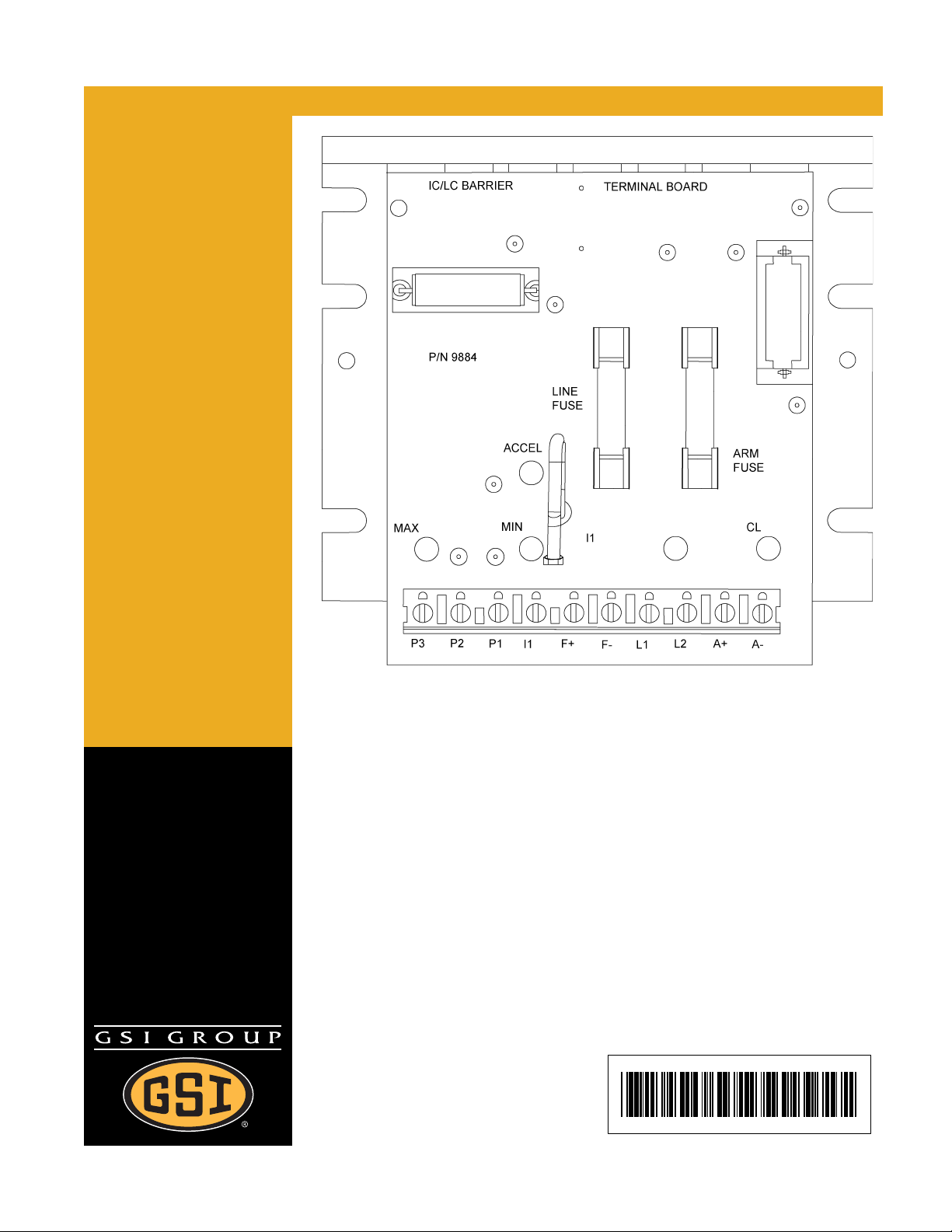
Figure 1A KBIC SCR Board
Figure 1B Woods SCR Board (Discontinued)
PNEG-1587 KBIC SCR Control Kit Installation 5
Page 6

2. Installation
Replacing the Woods Board
1. Disconnect the power to the circuit.
2. For ease of re-connection, record the colors and terminal numbers of all wires leading to the Woods
board. Disconnect wiring and remove board. Mount the KBIC board in approximately the same
location, oriented as shown in Figure 1A on Page 5. Note that additional holes must be drilled into
the mounting surface using a 9/64" drill bit. Try to keep power terminal L 1 and L2 in approximately
the same location as before to help prevent the need for longer wire lengths.
3. Mount the DIN Rail (D03-0013-BRK) next to the KBIC board if possible using a 9/64" drill bit. Use
the self tapping screws to secure the DIN Rail to the panel. Snap the SCR contactor (D03-0106)
onto the DIN Rail.
4. Reconnect the wires as follows:
Previous Woods Terminal New KBIC Terminal Previous Woods T erminal New KBIC Terminal
L1 T1 of SCR Contactor 1 P1
L2 T3 of SCR Contactor 2 P2
F1 F+ 3 P3
F2 F- 6 N.C. See text in Step 8
A1 A+ 7 N.C. See text in Step 7
A2 A
5. Strip the end of the supplied black 16 gauge wire and connect it to the wire between the L1 terminal
of the SCR contactor and the L1 terminal of the KBIC board. Now strip and connect a wire to the
L3 terminal of the SCR contactor and the L2 terminal of the KBIC board.
6. Connect the supplied white 18 gauge wire to the A2 terminal of the SCR contactor. Connect the
other end to any available AC neutral connection. This is usually a white wire labeled with a
number 2 at its connection point.
7. Connect the wire (See Figure 2A on Page 7) that was connected to terminal 7 on the Woods board
to the A1 terminal of the SCR contactor. If additional wire length is required, use part of the supplied
yellow 18 gauge wire and wire nut (HH-1462).
8. Connect the wire that was connected to terminal 6 to the supplied yellow 18 gauge wire using the
supplied wire nut (HH-1462) and the other end to a fused 110 VAC power sou rce. You can use any
connection that wire number 3 or number 27 is connected to.
6 PNEG-1587 KBIC SCR Control Kit Installation
Page 7

2. Installation
Figure 2A Wiring Diagram for all FFI Dryers
The board is ready to be calibrated unless the drye r is equipped with a Vari-Trol “VM” (Honeywell digital
type control), in which case the following additional step is required before calibration.
• If the dryer has a Honeywell Vari-Trol control and an Auto-Range module, connect the red wire
(#54) attached to the KBIC board to the terminal 1 of the Auto-Range module base. If this wire was
not present on your Woods board, please remove the wire with wire cutters.
PNEG-1587 KBIC SCR Control Kit Installation 7
Page 8

3. Adjusting SCR Motor Speed
Maximum Potentiometer Adjustment
With dryer unload circuit energized, set the SCR Speed Control knob on the ASC panel to 100%. Using
a small blade screwdriver, adjust the maximum potentiometer to obtain 155 VDC across the DC motor
armature terminals A+ and A- on the KBIC board. (NOTE: Some early M-Series dryers were designed
to operate with a 175 VDC armature voltage. Consult the factory if there is any question regarding these
early models.)
Minimum Potentiometer Adjustment
Set the SCR Speed Control knob on the ASC panel at the 10% setting. Adjust the minimum potentiometer
to obtain 15.5 VDC across the DC motor armature terminal A+ and A-.
Recheck the maximum potentiometer setting and readjust if necessary. Repeat and readjust the
minimum potentiometer if necessary. Rechecking the maximum and minimum potentiometer settings
once should be sufficient.
8 PNEG-1587 KBIC SCR Control Kit Installation
Page 9

4. Warranty
The GSI Group Warranty
THE GSI GROUP (GSI) WARRANTS ALL PRODUCTS WHICH IT MANUFACTURES TO BE FREE OF
DEFECTS IN MATERIAL AND WORKMANSHIP UNDER NORMAL USAGE AND CONDITIONS FOR
A PERIOD OF 12 MONTHS AFTER RETAIL SALE TO THE ORIGINAL END USER. THE
PURCHASER’S SOLE REMEDY AND GSI’S ONLY OBLIGATION SHALL BE TO REPAIR OR
REPLACE, AT GSI’S OPTION AND EXPENSE, PRODUCTS THAT, IN GSI’S SOLE JUDGMENT,
CONTAIN A MATERIAL DEFECT DUE TO MATERIALS OR WORKMANSHIP. ALL DELIVERY AND
SHIPMENT CHARGES TO AND FROM GSI’S FACTORY WILL BE PURCHASER’S RESPONSIBILITY.
EXPENSES INCURRED BY OR ON BEHALF OF THE PURCHASER WITHOUT PRIOR WRITTEN
AUTHORIZATION FROM AN AUTHORIZED EMPLOYEE OF GSI SHALL BE THE SOLE
RESPONSIBILITY OF THE PURCHASER.
EXCEPT FOR THE LIMITED WARRANTY EXPRESSED ABOVE, GSI MAKES NO FURTHER
WARRANTY OF ANY KIND, EXPRESS OR IMPLIED, INCLUDING, WITHOUT LIMITATION,
WARRANTIES OF MERCHANTABILITY OR FITNESS FOR A PARTICULAR PURPOSE OR USE IN
CONNECTION WITH (I) PRODUCT MANUFACTURED OR SOLD BY GSI OR (II) ANY ADVICE,
INSTRUCTION, RECOMMENDATION OR SUGGESTION PROVIDED BY AN AGENT,
REPRESENTATIVE OR EMPLOYEE OF GSI REGARDING OR RELATED TO THE CONFIGURATION,
INSTALLATION, LAYOUT, SUITABILITY FOR A PARTICULAR PURPOSE, OR DESIGN OF SUCH
PRODUCTS.
GSI SHALL NOT BE LIABLE FOR ANY DIRECT, INDIRECT, INCIDENTAL OR CONSEQUENTIAL
DAMAGES, INCLUDING, WITHOUT LIMITATION, LOSS OF ANTICIPATED PROFITS OR BENEFITS.
PURCHASER’S SOLE AND EXCLUSIVE REMEDY IS AS SET FORTH IN THE LIMITED WARRANTY
EXPRESSED ABOVE, WHICH SHALL NOT EXCEED THE AMOUNT PAID FOR THE PRODUCT
PURCHASED. THIS WARRANTY IS NOT TRANSFERABLE AND APPLIES ONLY TO THE ORIGINAL
PURCHASER. GSI SHALL HAVE NO OBLIGATION OR RESPONSIBILITY FOR ANY
REPRESENTATIONS OR WARRANTIES MADE BY OR ON BEHALF OF ANY DEALER, AGENT OR
DISTRIBUTOR OF GSI.
GSI ASSUMES NO RESPONSIBILITY FOR CLAIMS RESULTING FROM ERECTION DEFECTS OR
UNAUTHORIZED MODIFICATIONS TO PRODUCTS WHICH IT MANUFACTURED. MODIFICATIONS
TO PRODUCTS NOT SPECIFICALLY DELINEATED IN THE MANUAL ACCOMPANYING THE
EQUIPMENT AT INITIAL SALE WILL NULLIFY THE PRODUCT WARRANTY THAT MIGHT HAVE
BEEN OTHERWISE AVAILABLE.
THE FOREGOING WARRANTY SHALL NOT EXTEND TO PRODUCTS OR PARTS WHICH HAVE
BEEN DAMAGED BY NEGLIGENT USE, MISUSE, ALTERATION OR ACCIDENT. THIS WARRANTY
EXTENDS SOLELY TO ONLY PRODUCTS MANUFACTURED BY GSI. THIS WARRANTY IS
EXCLUSIVE AND IN LIEU OF ALL OTHER WARRANTIES EXPRESS OR IMPLIED. GSI RESERVES
THE RIGHT TO MAKE DESIGN OR SPECIFICATION CHANGES AT ANY TIME.
PRIOR TO INSTALLATION, PURCHASER HAS THE RESPONSIBILITY TO COMPLY WITH ALL
FEDERAL, STATE AND LOCAL CODES WHICH MAY APPLY TO THE LOCATION AND
INSTALLATION OF PRODUCTS MANUFACTURED OR SOLD BY GSI.
PHLEGAL: #1832020 v1 (139LG01!.DOC) (revised Decembe r 2005)
PNEG-1587 KBIC SCR Control Kit Installation 9
Page 10

This equipment shall be installed in accordance with
the current installation codes and applicable
regulations which should be carefully followed in all
cases. Authorities having jurisdiction should be
consulted before installations are made.
Copyright © 2007 by GSI Group
Printed in the USA
GSI Group
1004 E. Illinois St.
Assumption, IL 62510-0020
Phone: 1-217-226-4421
Fax: 1-217-226-4420
www.gsiag.com
 Loading...