

Page 1
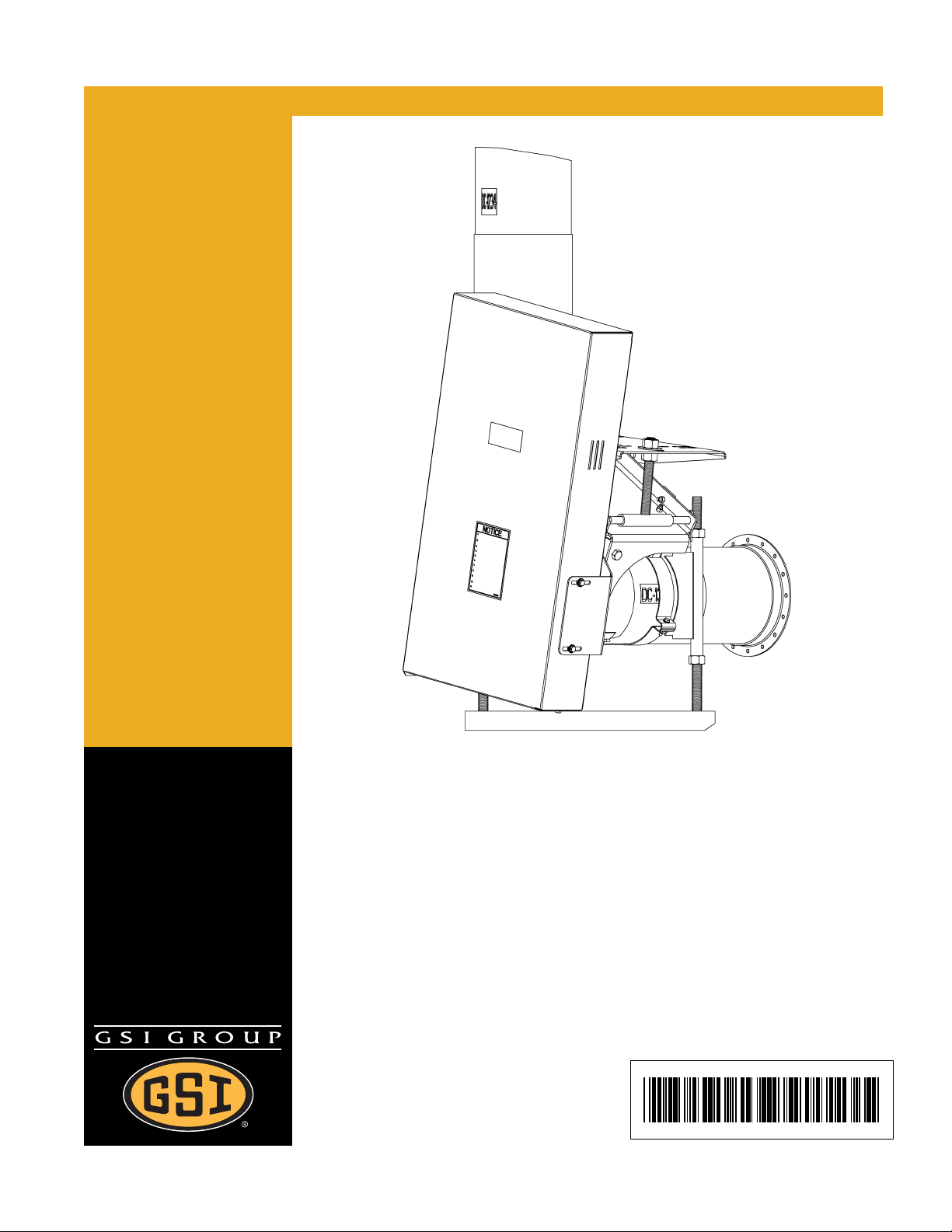
10" Commercial Vertical
Replacement Drive Kit
Installation Manual
PNEG-1583
Date: 04-16-08
PNEG-15 8 3
Page 2

2 PNEG-1583 10" Commercial Replacement Drive Kit
Page 3

Table of Contents
Contents
Chapter 1 Introduction ........................................................................................................................................ 4
Chapter 2 Safety ..................................................................................................................................................5
Safety Guidelines ............................................................................................................................... 5
Safety Instructions .............................................................................................................................. 6
Operator Qualifications ....................................................................................................................... 9
Chapter 3 Safety Decals ...................................................................................................................................10
Chapter 4 Installation ........................................................................................................................................ 11
Prepare the Powerhead ......... ... .......................................... ... .... ... ... ... ... .... ... ................................... 11
Assemble the Motor Mount Plate to the New Head Plate ................ ... ... .... ... ................................... 14
Install the Head Plate Assembly to the Auger .................................................................................. 15
Install Motor Mount Brace ................................................................................................................ 16
Assemble the Bearing to the Bearing Plate ...................................................................................... 17
Assemble the Bearing Plate Assembly to the Head Plate ................................................................ 17
Assemble Belt Guard Brackets to the Head Plate ............................................................................ 18
Install the Motor Mount Adjuster ....................................................................................................... 19
Install the Motor Plate ................................................................................................................. ...... 20
Install the Pulley ............................................................................................................................ ... 21
Install the Motor (NOT PROVIDED) ................................................................................................. 21
Install the Belts ................................................................................................................................. 22
Install the Belt Guard ........................................................................................................................ 23
Chapter 5 Parts List ..........................................................................................................................................24
Replacement Drive Kit Components ................................................................................................ 24
Chapter 6 Troubleshooting ..............................................................................................................................26
Chapter 7 Warranty ...........................................................................................................................................27
PNEG-1583 10" Commercial Replacement Drive Kit 3
Page 4

1. Introduction
READ THIS MANUAL carefully to learn how to properly use and install equipment. Failure to do so could
result in personal injury or equipment damage.
INSPECT the shipment immediately upon arrival. The customer is responsible for ensuring that all
quantities are correct. The customer should report and note any damage or shortage on the bill of lading
to justify their claim to the transport company.
THIS MANUAL SHOULD BE CONSIDERED a permanent part of your equipment and should be easily
accessible when needed.
This warranty provides you the assurance that the company will back its products when defects appear
within the warranty period. In some circumstances, the company also provide s field improvements, often
without charge to the customer, even if the product is out of warranty. Should the equipment be abused,
or modified to change its performance beyond the factory specifications, the warranty will be come void
and field improvements may be denied.
4 PNEG-1583 10" Commercial Replacement Drive Kit
Page 5
2. Safety
Safety Guidelines
This manual contains information that is important for you, the owner/operator, to know and understand.
This information relates to protecting personal safety and preventing equipment problems. It is the
responsibility of the owner/operator to inform anyone operating or working in the area of this equipment
of these safety guidelines. To help you recognize this information, we use the symbols that are defined
below. Please read the manual and pay attention to these sections. Failure to read this manual and its
safety instructions is a misuse of the equipment and may lead to serious injury or death.
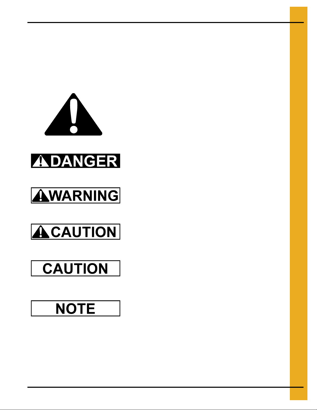
This is the safety alert symbol. It is used to alert you to
potential personal injury hazards. Obey all safety
messages that follow this symbol to avoid possible
injury or death.
DANGER indicates an imminently hazardous situation
which, if not avoided, will result in death or serious injury.
WARNING indicates a potentially hazardous situation
which, if not avoided, could result in death or serious injury.
CAUTION indicates a potentially hazardous situation which,
if not avoided, may result in minor or moderate injury.
CAUTION used without the safety alert symbol indicates a
potentially hazardous situation which, if not avoided, may
result in property damage.
NOTE indicates information about the equipment that you
should pay special attention.
PNEG-1583 10" Commercial Replacement Drive Kit 5
Page 6
2. Safety
Safety Instructions
Our foremost concern is your safety and the safety of others associated with this equipment. We want
to keep you as a customer. This manual is to help you understand safe operating procedures and some
problems which may be encountered by the operator and other personnel.
As owner and/or operator, it is your responsibility to know what requ irements, hazards and p recautions
exist, and to inform all personnel associated with the equipment or in the area . Safety precautions may
be required from the personnel. Avoid any alterations to the equipment. Such alterations may produce
a very dangerous situation where SERIOUS INJURY or DEATH may occur.
This equipment shall be installed in accordance with the current installation codes and applicable
regulations which should be carefully followed in all cases. Authorities having jurisdiction should be
consulted before installations are made.
Follow Safety Instructions
Carefully read all safety messages in this manual and
safety signs on your machine. Keep signs in good
condition. Replace missing or damaged safety signs. Be
sure new equipment components and repair parts include
the current safety signs. Replacement safety signs are
available from the manufacturer.
Learn how to operate the machine and how to use controls
properly. Do not let anyone operate without instruction.
Keep your machinery in proper working condition.
Unauthorized modifications to the machine may impair
the function and/or safety and affect machine life.
If you do not understand any part of this manual or need
assistance, contact your dealer.
Install and Operate Electrical Equipment Properly
Electrical controls should be installed by a qualified electrician
and must meet the standards set by the National Electrical Code
and all local and state codes.
Disconnect and lock out all power sources before installing
wires/cables or servicing equipment.
Read and Understand Manual
Electric Shock Hazard
6 PNEG-1583 10" Commercial Replacement Drive Kit
Page 7

Operate Unload Equipment Properly
• Untrained operators subject themselves and others to SERIOUS INJURY
or DEATH. NEVER allow untrained personnel to operate this equipment.
• NEVER work alone.
Operate Unload
• Keep children and other unqualified personnel out of the working
area at ALL times. Refer to the Start-Up section of this manual for
diagrams of the work area.
• Make sure ALL equipment is locked in position before operating.
• NEVER start equipment until ALL persons are clear of the work area.
• Keep hands and feet away from the auger intake and other moving parts.
• NEVER attempt to assist machinery operation or to remove trash from equipment while
in operation
Equipment Safely
2. Safety
• Be sure all operators are adequately rested and prepared to perform all functions of operating
this equipment.
• NEVER allow any person intoxicated or under the influence of alcohol or drugs to operate
the equipment.
• Make sure someone is nearby who is aware of the proper shutdown sequence in the event of an
accident or emergency.
• ALWAYS think before acting. NEVER act impulsively around the equipment.
• NEVER allow anyone inside a bin, truck or wagon which is being unloaded by an auger or
conveyor. Flowing grain can trap and suffocate in seconds.
• Use ample overhead lighting after sunset to light the work area.
• Keep area around intake free of obstacles such as electrical cords, blocks, etc. that might
trip workers.
• NEVER drive, stand or walk under the equipment.
• Use caution not to hit the auger when positioning the load.
• ALWAYS lock out ALL power to the equipment when finished unloading a bin.
• Be aware of pinch points. A pinch point is a narrow area between two surfaces that is likely to trap
or catch objects and so is a potential safety hazard.
PNEG-1583 10" Commercial Replacement Drive Kit 7
Page 8
2. Safety
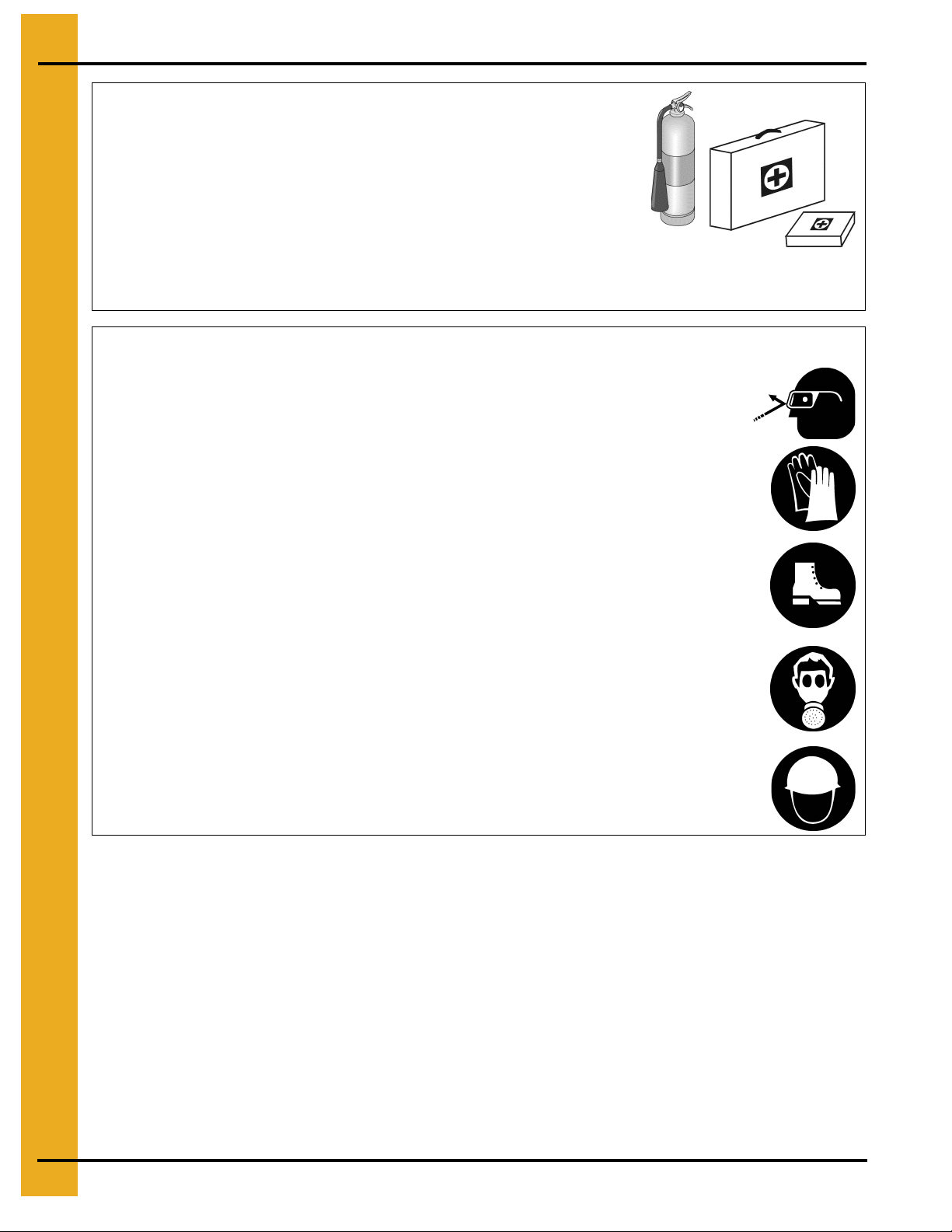
Prepare for Emergencies
Be prepared if fire starts.
Keep a first aid kit and fire extinguisher handy.
Keep emergency numbers for doctors, ambulance service,
hospital and fire department near your telephone.
Wear Protective Clothing
Wear close fitting clothing and safety equipment appropriate
to the job.
Remove all jewelry.
Keep Emergency Equipment
Quickly Accessible
Eye Protection
Long hair should be tied up and back.
Safety glasses should be worn at all times to protect eyes
from debris.
Wear gloves to protect your hands from sharp edges on
plastic or steel parts.
Wear steel toe boots to help protect your feet from falling
debris. Tuck in any loose or dangling shoe strings.
A respirator may be needed to prevent breathing potentially
toxic fumes and dust.
Wear hard hat to help protect your head.
Gloves
Steel Toe Boots
Respirator
Hard Hat
8 PNEG-1583 10" Commercial Replacement Drive Kit
Page 9

2. Safety
Operator Qualifications
A. The User/Operator must be competent and experienced to operate auger equipment. Anyone who
works with or around augers must have good common sense in order to be qualified. These
persons must also know and meet all other qualifications, such as:
i. Any person who has not read and/or does not understand all operation and safety procedures
is not qualified to operate any auger systems.
ii. Certain regulations apply to personnel operating power machinery. Personnel under the age
of 18 years may not operate power machinery, including augers. It is your responsibility, as
owner and/or supervisor, to know what these regulations are in your area or situation.
iii. Unqualified or incompetent persons are to remain out of the work area.
iv. O.S.H.A. (Occupational Safety and Health Administration) regulations state: “At the time of
initial assignment and at least annually thereafter, the employer shall instruct every employee
in the safe operation and servicing of all equipment with which the employee is, or will be
involved”. (Federal Occupational Safety and Health Standards for Agriculture. Sub Part D,
Section 19287.57 (a) (6)).
B. As a requirement of O.S.H.A., it is necessary for the employer to train the employee in the safe
operating and safety procedures for this auger. The sign-off sheet is for your convenience and
personal record keeping. All unqualified persons should always stay out o f work area. It is strongly
recommended that another qualified person who knows the shut down procedure is in the area in
the event of an emergency.
Date Employee Name Supervisor Name
PNEG-1583 10" Commercial Replacement Drive Kit 9
Page 10

3. Safety Decals
Check components shown below to ensure that the safety decals are in place and in good condition. If
a decal cannot be easily read for any reason or has been painted over, replace it immediately. Contact
your dealer or the manufacturer to order a replacement decal free of charge.
Contact:
GSI Group
1004 E. Illinois St.
Assumption, IL. 62510
Phone: 217-226-4421
SHEAR POINT
Keep hands clear of moving
parts. Do not operate with
guard removed. Disconnect
and lockout power before
servicing.
DC-994
D
DC-994
DC-994
DC-1379
Decal List
Part # Description Size
DC-994 Danger - Shear Point 4-1/2" x 2"
DC-1379 Notice 5-1/8" x 7-3/8"
10 PNEG-1583 10" Commercial Replacement Drive Kit
Page 11

4. Installation
Prepare the Powerhead
1. Disconnect and lock out all power to the 10'' commercial double-drive vertical unload auger.
A main power disconnect switch capable of being locked only in the OFF
position should be used. The switch should be locked out whenever work is
being done on the powerhead.
2. After the power has been disconnected and locked out, remove the existing belt guard assemb ly
on the horizontal drive.
a. Open the existing belt guard.
b. Relieve tension on the drive belts by adjusting the motor mount assembly.
c. Remove the drive belts.
d. Remove the motor pulley and drive sheave.
e. Unbolt and remove the existing belt guard assembly.
3. Remove the horizontal drive motor from the powerhead.
4. After the motor has been removed, loosen and remove the 3/4'' hex nut underneath the motor
mount sides, holding down the motor mount assembly. (See Figure 4A.)
Figure 4A
PNEG-1583 10" Commercial Replacement Drive Kit 11
Page 12

4. Installation
5. Remove the motor mount assembly.
6. Unbolt the four (4) 1/2'' x 1'' hex bolts, lock washers, and hex nuts, and remove the existing belt
guard brackets and motor mount sides. (See Figure 4B.)
7. Loosen and remove the lock collar on the 1-1/2'' four (4) hole flange bearing. (See Figure 4C.)
Figure 4B
Figure 4C
12 PNEG-1583 10" Commercial Replacement Drive Kit
Page 13

4. Installation
8. Remove the horizontal head plate from the vertical auger by removing the eight (8) 3/8'' x 1 '' hex
bolts, flat washers, lock washers and hex nuts. (See Figure 4D.)
9. Unbolt and remove the 1-1/2'' four (4) hole flange bearing. Where possible, this bearing will be
reused with the new horizontal drive parts. (See Figure 4E.)
Figure 4D
Figure 4E
PNEG-1583 10" Commercial Replacement Drive Kit 13
Page 14

4. Installation
Assemble the Motor Mount Plate to the New Head Plate
1. Position the motor mount plate over the new head plate so that the motor mount plate is almost
flush with the new head plate. (See Figure 4F.)
2. Bolt the motor mount plate to the head plate using four (4) 5/8" x 1-1/2" hex bolts and
nylock nuts. (See Figure 4G.)
Figure 4F
Figure 4G
14 PNEG-1583 10" Commercial Replacement Drive Kit
Page 15

4. Installation
Install the Head Plate Assembly to the Auger
1. Place the head plate assembly against the angle ring on the horizontal tube.
2. Rotate the head plate assembly so that the side of the motor mount plate is as clo se as p ossible
to the vertical connecting band, while making sure that the mounting holes in the head plate still
align with the mounting holes in the angle ring. (See Figure 4H.)
3. Bolt the head plate assembly to the angle ring on the horizontal tube using four (4) 3/8'' x 1''
hex bolts and serrated flange nuts. Use center hole in every three (3) hole group. (See Figure 4I.)
Figure 4H
Figure 4I
PNEG-1583 10" Commercial Replacement Drive Kit 15
Page 16

4. Installation
Install Motor Mount Brace
1. Position brace under motor mount plate aligning the three (3) holes with the slots in the brace.
2. Secure brace to motor mount plate using three (3) 3/8" x 1-1/4" serrated flange bolts and nylock nuts.
Figure 4J
3. Position 10" x 2" half band under tube and conn ect to brace using two (2) 5/16" x 1-3 /4" hex bolts,
four (4) 5/16" flat washers, and two (2) 5/16" nylock nuts.
Figure 4K
16 PNEG-1583 10" Commercial Replacement Drive Kit
Page 17

Assemble the Bearing to the Bearing Plate
1. Bolt the previously removed 1-1/2" four (4) hole flange bearing to the bearing plate using
four (4) 1/2'' x 1-1/2'' hex bolts, lock washers and hex nuts.
4. Installation
Figure 4L
Assemble the Bearing Plate Assembly to the Head Plate
1. Slide the bearing plate over the drive shaft and line up the bearing plate assembly in front
of the head plate.
2. Bolt the bearing plate assembly to the head plate using four (4) 3/8'' x 1'' hex bolts and serrated
flange nuts.
Figure 4M
PNEG-1583 10" Commercial Replacement Drive Kit 17
Page 18

4. Installation
3. Slide the bearing lock collar over the drive shaft up to the bearing. Using a hammer and punch,
continue to drive it onto the bearing in the clockwise direction, the same direction of the auger flight
rotation. (See Figure 4N.)
4. Tighten the set screw on the lock collar to the drive shaft.
Figure 4N
Assemble Belt Guard Brackets to the Head Plate
1. Place the left and right hand belt guard brackets up to the head plate.
2. Loosely bolt the brackets to the head plate using three (3) 3/8" serrated flange nuts and flat
washers. (See Figure 4O.)
Figure 4O
18 PNEG-1583 10" Commercial Replacement Drive Kit
Page 19

4. Installation
Install the Motor Mount Adjuster
1. Place the motor mount adjuster between the bottom pivot holes on the motor mount plate.
(See Figure 4P.)
2. Insert the pivot rod through the front bottom pivot hole, the motor mount adjuster, and the back
bottom pivot hole. Secure the pivot rod in place with two (2) 3/16'' x 2'' cotter pins. (See Figure 4P.)
3. With the cotter pins in the pivot rod, bend one tab of the cotter pin back so t hat it touches the pivot
rod, and bend the other tab of the cotter pin away from the first tab. (See Figure 4Q.)
Figure 4P
Figure 4Q
PNEG-1583 10" Commercial Replacement Drive Kit 19
Page 20

4. Installation
Install the Motor Plate
1. Thread one (1) of the motor mount adjustment nuts and one (1) motor mount adjustment washer
approximately 3/4 of the way down the motor mount adjuster’s threaded rod.
2. Once the nut and washer are in place, slip the motor plate over the adjuster and align its pivot
holes with the top pivot holes on the motor mount plate. (See Figure 4R.)
Figure 4R
3. Slide the motor mount pivot rod through the pivot holes on the motor plate and motor mount plate.
Insert the 3/4'' flat washer between the motor plate and the mo tor mount plate for the front pivot hole.
4. When the pivot rod begins to extend through the back pivot hole on the motor mount plate, install
the spacers BETWEEN it and the inner face of the motor plate. (See Figure 4S.)
Figure 4S
20 PNEG-1583 10" Commercial Replacement Drive Kit
Page 21

4. Installation
5. Secure the motor mount pivot rod in place with two (2) 3/16" x 2" cotter pins. With the cotter pins
in the pivot rod, bend one tab of the cotter pin back so that it touches the pivot rod, and bend the
other tab of the cotter pin away from the first tab.
6. Loosely install the upper motor mount adjustment washer and nut onto the threaded rod over the
motor mount plate.
Install the Pulley
1. Place and position the key into the keyway located on the drive shaft.
2. If applicable, assemble the supplied sheave bushing to the flight pulley. Place the flight pulley onto
the drive shaft with the set screw side of the flight pulley facing away from the bearing plate.
Position the flight pulley so that it is as close to the lock collar as possible, but not touching it.
3. Once the pulley is appropriately positioned, tighten the set screw with a hex head wrench to
secure it to the drive shaft. (See Figure 4T.)
Figure 4T
Install the Motor (NOT PROVIDED)
1. Attach the motor to the motor mount plate using appropriate bolts, lock washers, and
hex nuts. (See Table below.)
Motor Bolt Selection
Motor Frame Hex Bolt Quantity and Size
56
(4) 5/16"-18 x 1-1/4"143T
145T
182T
184T
213T
215T
254T
256T
PNEG-1583 10" Commercial Replacement Drive Kit 21
(4) 3/8"-16 x 1-1/4"
(4) 1/2"-13 x 1-3/4"
Page 22

4. Installation
2. Install the drive pulley onto motor shaft making sure that it is aligned with the flight pulley. It may
be necessary to move spacers to gain shaft alignment. Use the 3/4'' flat washer where the 1/2''
spacers cannot be used. (See Figure 4U.)
Figure 4U
Install the Belts
1. Place the belts onto the pulleys.
2. First, screw the lower motor mount adjustment nut upward, raising the motor mount plate and
putting tension on the belts.
3. Once the desired tension is reached, tighten the upper motor mount adjustment nut do wn onto the
motor plate locking it into place.
22 PNEG-1583 10" Commercial Replacement Drive Kit
Page 23

4. Installation
Install the Belt Guard
1. With the belts properly tensioned, remove the bottom belt guard cover.
2. Slip the belt guard down over the motor and drive sheaves, enclosing the drive belts.
3. Bolt the belt guard loosely to the belt guard brackets with four (4) 3/8'' x 1'' flange bolts.
4. Center the belt guard slot with the motor shaft and the auger drive shaft. Make sure the belt guard
DOES NOT contact the pulleys, belts, or bearing, and tighten the belt guard to the belt guard
mounting bracket(s).
5. Once the belt guard is secured, slide the bottom belt guard cover back into place and secure it
with the 3/8'' x 1'' flange bolt previously removed.
Figure 4V
PNEG-1583 10" Commercial Replacement Drive Kit 23
Page 24

5. Parts List
Replacement Drive Kit Components
24 PNEG-1583 10" Commercial Replacement Drive Kit
Page 25

Double-Drive Vertical Retro Belt Guard Kit
Ref # Part # Description
1 GK7851 Double Drive Vertical 10" Retro Belt Guard
2 MHC00894 V-Belt BX78
3 GK7855 Double Drive Vertical 10" Retro Belt Guard Bracket
4 GK6986 Motor Plate
5 GK7013 Motor Mount Pivot Rod
6 GK7853 Double Drive Vertical 10" Retro Motor Mount
7 GK6942 Motor Mount Adjustment Weldment
8 GK7012 Motor Mount Adjustment Pivo t Rod
9 GK7911 Double Drive Vertical 10" Retro Brace
10 GK1057 Half Band 10" x 2" 12 Gauge Galvanized
11 GK7852 Double Drive Vertical 10" Retro Head Plate
12 GK7854 Double Drive Vertical 10" Retro Bearing Plate
13 GK1343 1-1/2" 4 Hole Flange Bearing w/ Lock Collar
5. Parts List
GK2570 18.4" 3 Belt Sheave
14
GK2567 18.4" 2 Belt Sheave
15 GK4248 1-1/2" Bore SK Bushing
16 S-9065 3/8"-16 x 1" Serrated Flange Bolt Zinc Grade 5
17 S-845 5/16" Flat Washer Yellow Dip Grade 2
18 S-968 3/8"-16 Serrated Flange Nut Zinc Grade 5
19 GK7014 Pivot Spacer Tube
20 S-866 3/4" Flat Washer Zinc Grade 2
21 S-6994 3/16" x 2" Cotter Pin
22 S-7835 1" Flat Washer Zinc
23 S-240 1"-8 Hex Nut Zinc Grade 5
24 S-4109 5/8"-11 x 1-1/2" Hex Hea d Tap Bolt Yellow Dip Grade 8
25 S-8349 5/8"-11 Nylock Nut Zinc Grade 2
26 S-7383 3/8"-16 Nylock Nut Zinc Grade 5
27 S-9066 3/8"-16 x 1-1/4" Serrated Flange Bolt Zinc Grade 5
28 S-7149 5/16"-18 x 1-3/4" Hex Head Cap Screw Zinc Grade 5
29 S-1937 5/16" Flat Washer Zinc Grade 2
30 S-7382 5/16"-18 Nylock Nut Zinc Grade 5
31 S-968 3/8"-16 Serrated Flange Nut Zinc Grade 5
32 S-7927 3/8"-16 x 1" Serrated Flange Bolt Yello w Dip Grade 8
33 S-8760 1/2"-16 x 1-1/2" Hex Head Cap Screw Zinc Grade 5
34 S-236 1/2" Lock Washer Zinc
35 S-7510 1/2"-13 Hex Nut Zinc Grade 2
36 S-9181 3/8" x 3" Square Key
PNEG-1583 10" Commercial Replacement Drive Kit 25
Page 26

6. Troubleshooting
Problem Possible Cause Solution
Auger vibration Drive belt may be overtightened, putting head stub
and flight in a bind. Damage can occur to the auger
flighting, thus causing noise. Damage is usually
caused from foreign material having been run
through the auger.
Low capacity The auger may not be getting enough grain. Check that the intake has not bridged over,
The auger is moving too slowly. Check the auger speed. Speeds slower than
Auger plugs The auger may be getting too much grain, causing
“jamming” inside the housing.
The motor may be too small or wired improperly.
The grain may be wet. If wet grain or other hard-to-move material is
The auger may be jammed with foreign material. Be sure there is no foreign material in the
It may be necessary to remove the flighting
for inspection.
Adjust the drive belt to the proper tension.
restricting flow. The exposed flighting at the
auger intake should be covered with grain to
achieve maximum capacity.
the recommended speed will result in
low capacity.
Decrease the amount of grain the auger
is gathering.
If the motor is a newer light-weight
aluminum type, the next larger size should
be considered.
being augered, use a larger size motor than
recommended for normal use.
auger such as sacks, tarp corners, etc.
The discharge end may be plugged. Make sure the discharge end of the auger is
not plugged. A plug of the discharge end will
cause an auger plug.
26 PNEG-1583 10" Commercial Replacement Drive Kit
Page 27

7. Warranty
The GSI Group Limited Warranty
The GSI Group, Inc. (“GSI”) warrants products which it manufactures to be free of defects in materials
and workmanship under normal usage and conditions for a period of 12 months after sale to the orig inal
end-user or if a foreign sale, 14 months from arrival at port of discharge, whichever is earlier. The
end-user’s sole remedy (and GSI’s only obligation) is to repair or replace, at GSI’s option and expense,
products that in GSI’s judgment, contain a material defect in materials or workmanship. Expenses
incurred by or on behalf of the end-user without prior written authorization from the GSI Warranty Group
shall be the sole responsibility of the end-user.
Warranty Extensions:
The Limited Warranty period is extended for the following products:
Product Warranty Period
AP Fans and Flooring
Cumberland
Feeding/Watering
Systems
Grain Systems
Performer Series Direct Drive Fan Motor 3 Years
All Fiberglass Housings Lifetime
All Fiberglass Propellers Lifetime
Apex Flooring 10 Years *
Feeder System Pan Assemblies 5 Years **
Feed Tubes (1.75" and 2.00") 10 Years *
Centerless Augers 10 Years *
Watering Nipples 10 Years *
Grain Bin Structural Design 5 Years
Portable Dryers (Excluding Motors) 2 Years
* Warranty prorated from list price:
0 to 3 years - no cost to end-user
3 to 5 years - end-user pays 25%
5 to 7 years - end-user pays 50%
7 to 10 years - end-user pays 75%
** Warranty prorated from list price:
0 to 3 years - no cost to end-user
3 to 5 years - end-user pays 50%
Conditions and Limitations:
THERE ARE NO WARRANTIES THAT EXTEND BEYOND THE LIMITED WARRANTY DESCRIPTION
SET FORTH ABOVE. SPECIFICALLY, GSI MAKES NO FURTHER WARRANTY OF ANY KIND,
EXPRESS OR IMPLIED, INCLUDING, WITHOUT LIMITATION, WARRANTIES OF
MERCHANTABILITY OR FITNESS FOR A PARTICULAR PURPOSE OR USE IN CONNECTION
WITH: (I) PRODUCT MANUFACTURED OR SOLD BY GSI OR (II) ANY ADVICE, INSTRUCTION,
RECOMMENDATION OR SUGGESTION PROVIDED BY AN AGENT, REPRESENTATIVE OR
EMPLOYEE OF GSI REGARDING OR RELATED TO THE CONFIGURATION, INSTALLATION,
LAYOUT, SUITABILITY FOR A PARTICULAR PURPOSE, OR DESIGN OF SUCH PRODUCTS.
GSI shall not be liable for any direct, indirect, incidental or consequential damages, including, without
limitation, loss of anticipated profits or benefits. The sole and exclusive remedy is set forth in the Limited
Warranty, which shall not exceed the amount paid for the product purchased. This warranty is not
transferable and applies only to the original end-user. GSI shall have no obligation or responsibility for
any representations or warranties made by or on behalf of any dealer, agent or distributor.
GSI assumes no responsibility for claims resulting from construction defects or unauthorized
modifications to products which it manufactured. Modifications to products not specifically delineated in
the manual accompanying the equipment at initial sale will void the Limited Warranty.
This Limited Warranty shall not extend to products or parts which have been damaged by negligent use,
misuse, alteration, accident or which have been improperly/inadequately maintained. This Limited
Warranty extends solely to products manufactured by GSI.
Prior to installation, the end-user has the responsibility to comply with federal, state and local codes
which apply to the location and installation of products manufactured or sold by GSI.
9101239_1_CR_rev3.DOC (revised February 2008
PNEG-1583 10" Commercial Replacement Drive Kit 27
Page 28

This equipment shall be installed in accordance with
the current installation codes and applicable
regulations which should be carefully followed in all
cases. Authorities having jurisdiction should be
consulted before installations are made.
Copyright © 2008 by GSI Group
Printed in the USA
GSI Group
1004 E. Illinois St.
Assumption, IL 62510-0020
Phone: 1-217-226-4421
Fax: 1-217-226-4420
www.gsiag.com
 Loading...