

Page 1
PNEG-1579
12" & 16" Series II Sweep
(Special)
Owner's Manual
06-08-07
PNEG-1579
Page 2
Model Number of My Sweep:
Date Delivered:
Date Installed:
The manufacturer reserves the right to improve it's product whenever
possible and practical to do so. We reserve the right to change, improve
and modify products at any time without obligation to make changes,
improvements and modifications on equipment sold previously.
Page 3

Table of Contents
TABLE OF CONTENTS
Safety ...................................................................................................4-8
Introduction...........................................................................................9-10
Decals..................................................................................................11-14
Operator Qualifications ........................................................................15
General Product Information ................................................................ 16-19
Assembly Section
Back Shield .................................................................................... 20
Flighting .......................................................................................... 22
Hanger Bracket ..............................................................................23
Flange Bearing ...............................................................................24
Gear Reducer................................................................................. 24
Drive Axle & Bearing Support .........................................................25
Reducer Mounting Plate & Reducer ............................................... 27
Key Alignment................................................................................. 27
Tractor Motor ..................................................................................28
Guard Assembly.............................................................................29
Tractor Wheel Assembly ................................................................ 30
Counter Weight ..............................................................................31
Weight Channel Extension Kit........................................................32
Motor Jack & Base Assembly......................................................... 33
Motor Installation.............................................................................34
Sheave Installation.......................................................................... 35
Electrical Assembly ........................................................................37
Jack Support .................................................................................. 43
Center Pivot.................................................................................... 45
Control Panel.................................................................................. 48
Start-Up................................................................................................50
Operation .............................................................................................52
Shutdown .............................................................................................54
Storage Prep aration .............................................................................54
Maintenance .........................................................................................55
Control Panel Schematics ................................................................... 62
Troubleshooting....................................................................................65
Part Lists..............................................................................................66
Warranty...............................................................................................Inside Back Cover
Personnel operating or working around this equipment should read this
manual. This manual must be delivered with equipment to its owner.
Failure to read this manual and its safety instructions is a misuse of the
equipment. Any misuse of the equipment may void the warranty.
PNEG-720-G2 12" & 16" Series II Sweep
3
Page 4
Safety
SAFETY
GSI equipment is built to provide many years of dependable service to our
customers through durable craftsmanship.
One of the most important aspects of GSI engineering is SAFETY 1
throughout all product lines. At GSI - safety is NO ACCIDENT!
That is why GSI is implementing its SAFETY 1
safety decals, or owner/operator manuals, simply contact GSI, and we will supply
you with them FREE OF CHARGE!
While it is our main goal for GSI to be the world leader in auger manufacturing, it
is always our first priority to keep our customers safe.
If you need any of the above listed safety items or have safety questions, please
contact GSI:
st
program. Should you ever need
st
design
The GSI Group
PO Box 20
1004 E. Illinois Street
Assumption, IL 62510
Ph: 217-226-4421
4 12" & 16" Series II Sweep PNEG-720-G2
Page 5
Safety
SAFETY GUIDELINES
This manual contains information that is important for you, the owner/operator , to know and
understand. This information relates to protecting personal safety and preventing
equipment problems. It is the responsibility of the owner/operator to inform anyone operating
or working in the area of this equipment of these safety guidelines. T o help you recognize this
information, we use the symbols that are defined below . Please read the manual and pay
attention to these sections. Failure to read this manual and it’s safety instructions is a misuse of
the equipment and may lead to serious injury or death.
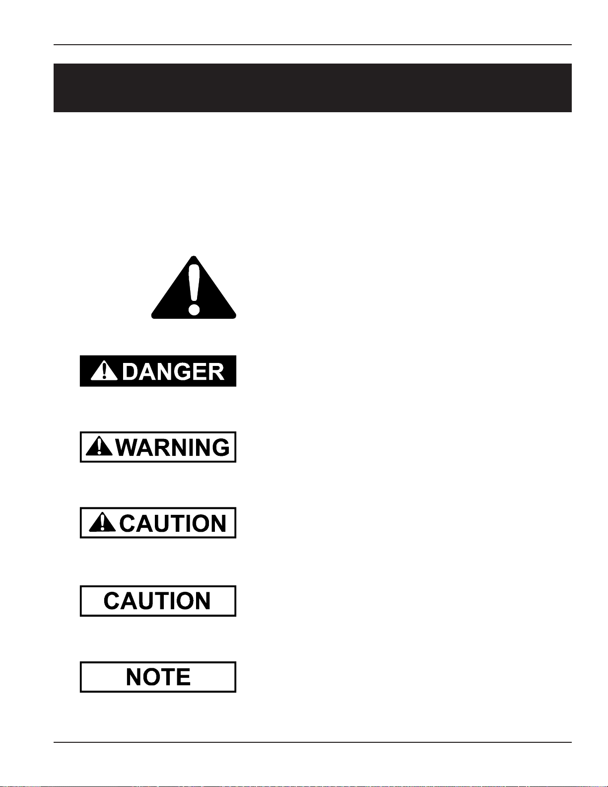
This is the safety alert symbol. It is used to alert you
to potential personal injury hazards. Obey all
safety messages that follow this symbol to avoid possible
injury or death.
DANGER indicates an imminently hazardous situation which,
if not avoided, will result in death or serious injury .
WARNING indicates a potentially hazardous situation
which, if not avoided, could result in death or serious injury .
CAUTION indicates a potentially hazardous situation which,
if not avoided, may result in minor or moderate injury .
CAUTION used without the safety alert symbol indicates a
potentially hazardous situation which, if not avoided, may
result in property damage.
PNEG-720-G2 12" & 16" Series II Sweep
NOTE indicates information about the equipment that you
should pay special attention to.
5
Page 6
Safety
Safety Instructions
GSI’s principle concern is your safety and the safety of others associated with grain handling equipment.
We want to keep you as a customer. This manual is to help you understand safe operating procedures and
some problems which may be encountered by the operator and other personnel.
As owner and/or operator , it is your responsibility to know what requirements, hazards and precautions
exist, and to inform all personnel associated with the equipment or in the area. Safety precautions may be
required from the personnel. Avoid any alterations to the equipment. Such alterations may produce a very
dangerous situation, where SERIOUS INJURY or DEATH may occur.
This equipment shall be installed in accordance with the current installation codes and applicable regulations which should be carefully followed in all cases. Authorities having jurisdiction should be consulted
before installations are made.
OPERATE UNLOAD EQUIPMENT PROPERLY
Make sure ALL equipment is locked in position before operating.
NEVER start equipment until ALL persons are clear of the work area.
Use caution not to hit the auger when positioning the load.
Operate Unload
Be sure all operators are adequately rested and prepared to
perform all functions of operating this equipment.
Untrained operators subject themselves and others to SERIOUS INJURY
or DEA TH. NEVER allow untrained personnel to operate this equipment.
Keep children and other unqualified personnel out of the working area at ALL times.
NEVER allow any person intoxicated or under the influence of alcohol or drugs to operate the equipment.
NEVER work alone. Make sure someone is nearby who is aware of the proper shutdown sequence in
the event of an accident or emergency .
AL W A YS think before acting. NEVER act impulsively around the equipment.
NEVER allow anyone inside a bin, truck or wagon which is being unloaded by an auger or conveyor .
Flowing grain can trap and suffocate in seconds.
Use ample overhead lighting after sunset to light the work area.
Keep area around intake free of obstacles such as electrical cords, blocks, etc. that might trip workers.
Equipment Safely
NEVER drive, stand or walk under the equipment.
AL W A YS lockout ALL power to the equipment when finished
unloading a bin.
Be aware of pinch points. A Pinch point is a narrow area between two surfaces that is likely to trap or
catch objects and so is a potential safety hazard.
6 12" & 16" Series II Sweep PNEG-720-G2
Page 7
FOLLOW SAFETY INSTRUCTIONS
Carefully read all safety messages in this manual and safety
signs on your equipment. Keep signs in good condition.
Replace missing or damaged safety signs. Be sure new
equipment components and repair parts include the current
safety signs. Replacement safety signs are available from the
manufacturer.
Learn how to operate the machine and how to use controls
properly . Do not let anyone operate without instruction.
Keep your machinery in proper working condition. Unauthorized modifications to the machine may impair the function
and/or safety and affect machine life.
If you do not understand any part of this manual and need
assistance, contact your dealer.
Safety
Read and
Understand
Manual.
KEEP HANDS AWAY FROM MOVING PARTS
Keep hands and feet away from auger intake and other moving parts.
Rotating auger can sever a person's limbs or even kill.
Keep hair, loose clothing, and shoestrings away from rot ating and moving
parts. NEVER wear loose fitting clothing when working around augers.
AL WA YS turn of f and lock out all power sources before servicing equipment.
AL W A YS keep belt and chain guards in place during operation.
NEVER attempt to assist machinery operation or to remove trash from equip-
ment while in operation.
OPERATE MOTOR PROPERLY
In an emergency, shut down the power source.
Turn of f and lock out all power sources before performing any maintenance.
Rotating Auger
Do not operate electric motor equipped units until motors are properly
grounded.
Disconnect power on electrical driven units before resetting motor overloads.
Do not repetitively stop and start the drive in order to free a plugged condi-
tion. Jogging the drive in this type of condition can damage the auger and/or
drive components.
PNEG-720-G2 12" & 16" Series II Sweep
Electric
Shock
Hazard.
7
Page 8
Safety
PRACTICE SAFE MAINTENANCE
Understand service procedures before doing work.
Keep area clean and dry.
Never lubricate, service, or adjust machine while it is in
operation. Keep hands, feet, and clothing from rotating
shafts, screws, belts, or other moving equipment.
Keep all parts in good condition and properly installed.
Fix damage immediately. Replace worn or broken
parts. Remove any build up grease, oil, or debris.
WEAR PROTECTIVE CLOTHING
Wear close fitting clothing and safety equipment
appropriate to the job.
Safety glasses should be worn at all times to
protect eyes from debris.
Maintain
Equipment
and Work
Area.
Eye Protection
Gloves
Wear gloves to protect your hands from sharp
edges on plastic or steel parts.
Use a respirator to prevent breathing potentially
toxic fumes and dust.
Wear hard hat and steel toe boots to help
protect your head and toes from falling debris.
Remove all jewelry .
Tuck in any loose or dangling shoe strings.
Long hair should be tied up and back.
PREPARE FOR EMERGENCIES
Be prepared if fire starts.
Steel Toe
Boots
Respirator
Hard Hat
Keep a first aid kit and fire extinguisher handy .
Keep emergency numbers for doctors, ambulance ser-
vice, hospital, and fire department near your telephone.
Keep Emergency Equipment
Quickly Accessible.
8 12" & 16" Series II Sweep PNEG-720-G2
Page 9

Introduction
PRODUCT INTRODUCTION
Congratulations! Your selection of the GSI Series 2 Sweep was a wise investment. It will give you years of
dependable service. The main function of the Series 2 Sweep is to clean out the remaining grain, from the
bin, after all gravity unloading has finished. The GSI Series 2 Sweep is a single pass sweep only. The unit will
only operate in a round grain bin equipped with a center sump in the bin floor. NOTE: The bin manufacturer
should be contacted for their recommendations on your bin’s structural integrity. The following are sweep
criteria recommendations.
ISSUES RECOMMENDATIONS
Flooring
Center Sump Size
The flooring type of choice is concrete. However, the sweep can be
used on a full aeration floor. When installing a sweep on a full aeration floor, the floor manufacturer should be cont acted for proper
recommendations concerning supporting of the floor. It is required to
lay a track, 10 Ga. minimum with slip resistant finish, under the sweep
at the points of contact of the tractor drive tires, and 10 Ga minimum,
under the points of contact of the intermediate jacks over any type of
aeration flooring, both full floor or flush floor aeration. A chart is
included that shows radius dimensions locating the points of contact
between the sweep and the bin floor. The dimensions may be used to
figure the material quantities of track to support the sweep across the
aeration flooring. The track material is not supplied with the sweep
and must be supplied by the installer or purchased from GSI. The
dimensions are approximate and the assembled sweep should be
checked for exact points of contact.
When installing a 12" standard sweep, the minimum recommended
opening is 36" x 36". With a 16" standard sweep, it is 42" x 42". If
installing a sump with collector ring, the opening will be 42" x 42" for
both sweep sizes.
The sump hopper supplied by GSI was designed with sufficient clearance around the collector ring housing to allow grain to gravity flow
thru the hopper and be carried away by the material handling equipment below. 42 3/4" is the maximum opening size to allow rolling
clearance for the casters assembled to the head end jack. If made
smaller, grain flow may be decreased to an unacceptable level.
Number of Intermediate
Sumps.
PNEG-720-G2 12" & 16" Series II Sweep
**Flow of grain is limited to 15,000 BPH when using this sump and
collector ring housing assembly . The collector ring housing extends
22 1/2" down from the floor surface and is approximately 14 1/4" x 14
1/4" in size.
It is recommended to install the intermediate sumps on a maximum of
10’ centers where the sweep will be parked during storage. The extra
sumps will help clean out the grain in front of the sweep reducing the
start-up load. Doing this will save labor dollars and hours of work to
uncover the sweep and can help the sweep during start-up. The
sweep should be parked behind the intermediate sumps with the
sumps on the auger side of the sweep.
9
Page 10

Introduction
Routing the Power Supply
to the Sweep.
Floor Level Tolerance
Bin Roundness Tolerance
Bin Opening Size
Required for Installation
There are three (3) options for routing the power. The most used option is
to run the cords out the door in the sidewall. Another option is to use the
hopper sump with collector ring. This allows the power to be transferred
through a mechanical device in the center sump and does not twist any
cords. This method is popular overseas. Last, is by using the pivot kit,
which routes the power cord through the center sump. Using this kit
requires the sweep to be backed up to the start point after sweeping. The
pivot kit is not the preferred choice due to the cord twisting repeatedly.
The top edge of the sump hopper and the top edge of the "X" brace
support must be level with the floor. The floor must be level within 3/4"
plus or minus, preferably less. Any high or low points must be gradually
sloped. The change in elevation should be no more than 3/4" over 60".
Diameter tolerances are limited by foundation limits and sweep operation as well as structural issues. For 72’ diameter and larger the overall
tolerance would be plus or minus 1 1/4” on the radius, plus or minus 1”
on 42’-66’ diameter bins and plus or minus ¾” on 30’ – 39’ bins.
The tail section is the largest piece of a standard Series 2 Sweep. The
dimensions for a 16" tail section are 23 1/2" x 55 1/4". If the bin wall is
not too thick, this unit should fit thru a 23 1/2" x 47" opening. The dimensions for a 12" tail section are 21 1/4" x 51 1/2" Again, if the bin wall is
not too thick the section should fit thru an opening 21 1/2 x 45"
Electrical Requirements
GSI offers a special Knock Down Sweep, uniquely designed for storage
units with small doors. This sweep is broken into 10 main pieces that can
fit through a door as small as 30 1/2" in diameter for 16", 27 1/2" in diameter for 12", or a 20" x 24" rectangular door. The components are then
assembled inside the storage unit.
Electrical controls and wiring should be installed by a qualified electrician. The motor disconnect switches and conductor cables should comply
with the National Electrical and any local codes which may apply.
A main power disconnect switch capable of being locked only in the
OFF position should be used. Disconnect and lock out the power
before servicing the equipment, entering the bin, or resetting the
motor overloads.
The control panel MUST be mounted OUTSIDE the bin near the door. It
must be located so the operator has a full view of the equipment and can
see that all personnel are clear. It must NEVER be installed inside the
bin. The foot switch has to be plugged into the control panel and depressed before the sweep is operational. It has a 10' cord so the sweep
can only be monitored from OUTSIDE the bin. The thermal protection
cord must also be plugged in before the sweep will operate.
10 12" & 16" Series II Sweep PNEG-720-G2
Page 11
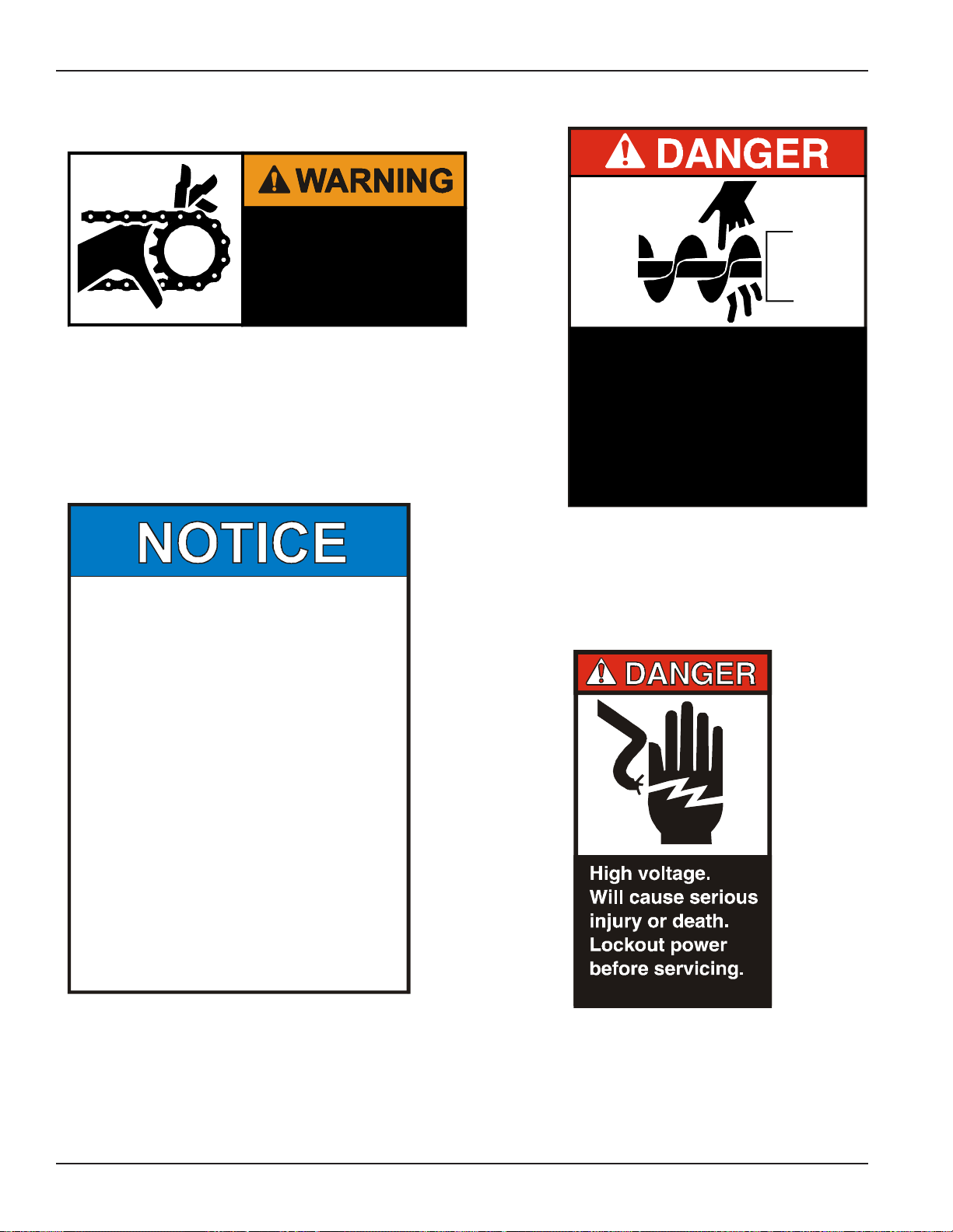
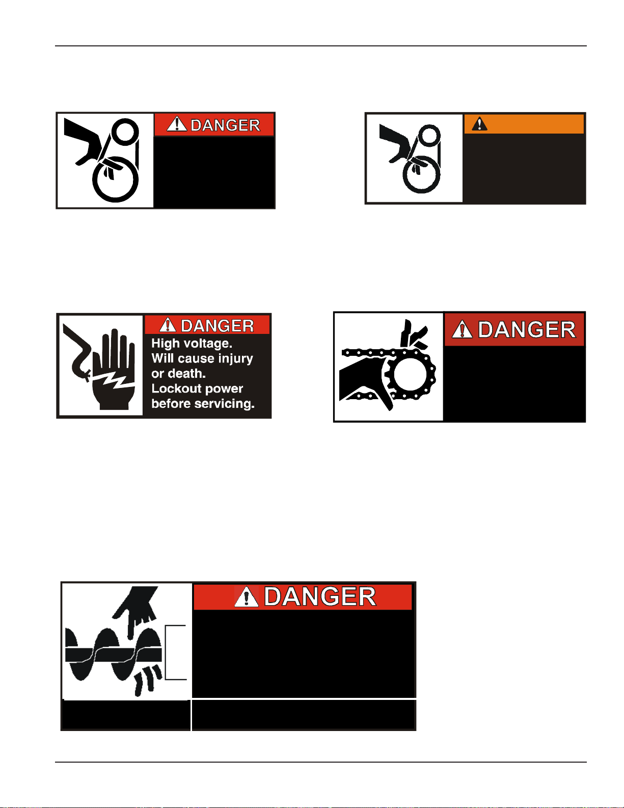
DECALS
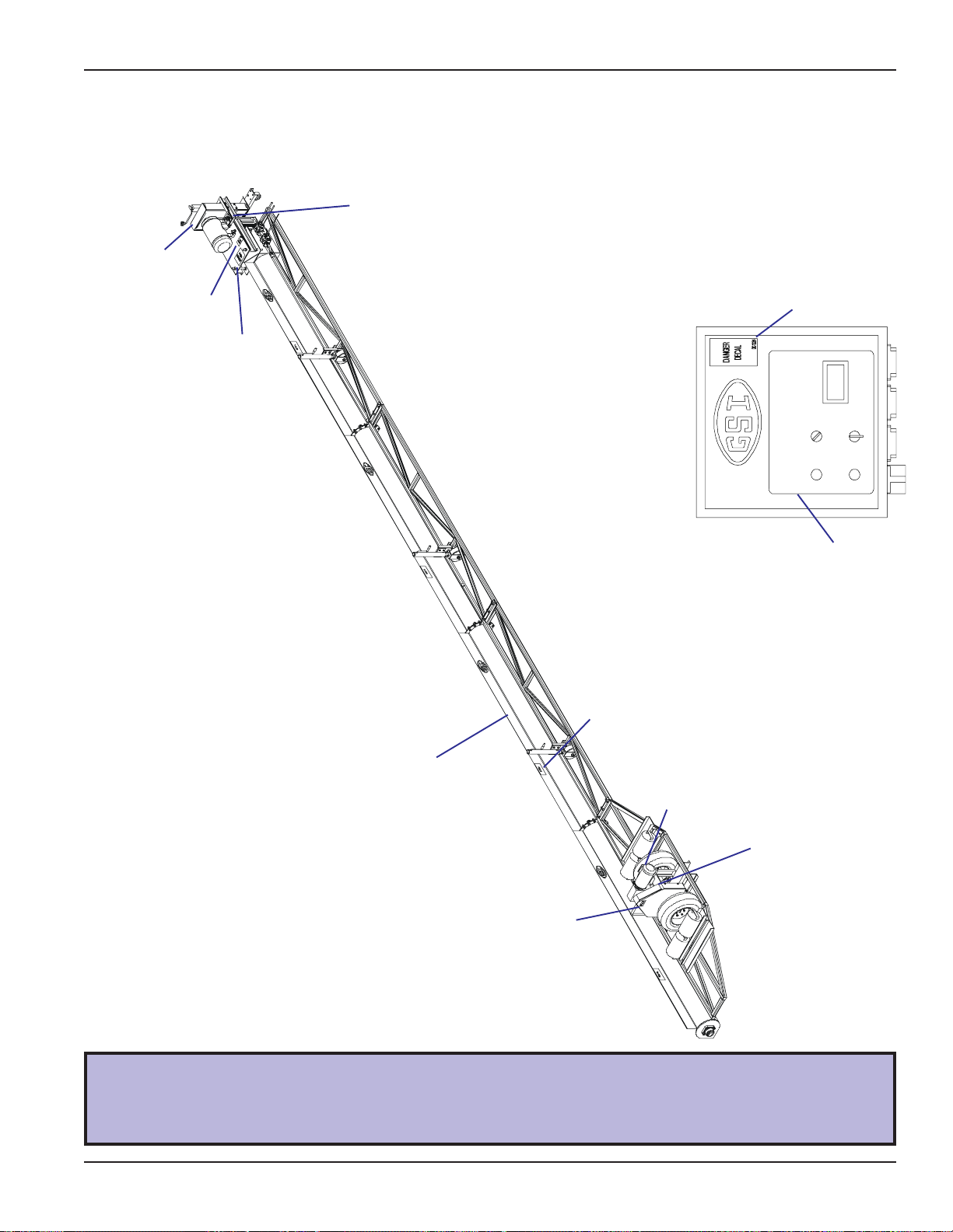
A. The images below show the location of the decals and safety signs which should appear on
the Series II Sweep. (refer to pg. 13-15 for decals)
Decal “E” (DC-994) on
corner of motor mount
Decal “F” (DC-995) on
top of belt guard
Decal “D” (DC-1224) on
corner of motor mount
Decal “C” (DC-1233)
centered on motor mount
Control panel located
outside of bin.
Decals
Decal “D” (DC-1224) on
front corner of control
panel
Decal “I” (DC-834) one (1) per
section centered on back of top
flange
Decal “G” (DC-889) on
corner of motor plate
Decal “B” (DC-1416) two (2) per
section on front of top flange
Decal “A” (DC-1386) on
exterior of chain guard
Please remember safety signs provide important safety information for people working
near bin unloading equipment that is in operation.
Any safety signs that are worn, missing, illegible or painted over should be replaced
immediately. Obtain FREE replacements by contacting GSI.
Decal “G” (DC-889)
three (3) on interior of
control panel
Decal “H” (DC-1382) on
corner of mount plate
PNEG-720-G2 12" & 16" Series II Sweep
11
Page 12
Decals
DECALS (CONT.)
SHEAR POINT
Moving parts can
crush and cut. Keep
hands clear of
sprocket and chain.
Decal “A”
Location: Exterior of chain guard
Size: 2” x 4 1/2”
Part No.: DC-1386
1. READ AND UNDERSTAND THE OPERATOR’S MANUAL
AND ALL SAFETY INSTRUCTIONS.
2. DO NOT OPERATE WHILE UNDER THE INFLUENCE OF
DRUGS OR ALCOHOL.
3. DO NOT OPERATE UNLESS ALL SAFETY EQUIPMENT ,
SWITCHES, GUARDS AND SHIELDS ARE SECURELY IN
PLACE AND OPERATIONAL .
4. ALLOW ONLY TRAINED AUTHORIZED PERSONNEL IN
THE OPERATING AREA.
5. ANY ELECTRICAL WIRING OR SERVICE WORK MUST
BE PERFORMED BY A QUALIFIED ELECTRICIAN. IT MUST
MEET ALL STATE AND LOCAL E LEC TR IC A L CODE S.
Danger Do not put fingers in Auger
6. DO NOT ALLOW CHILDR EN IN THE AREA OF OPERATION.
7. KEEP HANDS, FEET AND CLOTHING AWAY FROM `
MOVING P ART S.
8. DIS C ON N E CT AND LOCK OU T POW ER BEFORE
MAKING ANY ADJUSTMENTS OR PERFORMING ANY
SERVICE WORK.
9. DISCONNECT POWER PRIOR TO RESETTING ANY
MOTOR OVERLOAD.
10. MAKE CERT AI N ALL ELE CT RIC MOT ORS AR E GROUNDED.
11. REPLACE ALL WORN OR DAMAGED LABELS IMMEDIATELY.
DC-1379
Decal “C”
Location: Centered on motor mount
Size: 5 1/2” x 7 3/8”
Part No.: DC-1379
DC-1386
ROTATING AUGER!
• DISCONNECT AND LOCKOUT POWER BEFORE
SERVICING, ADJUSTING OR CLEANING.
• KEEP HANDS, FEET, HAIR AND LOOSE
CLOTHING AWAY FROM ROTATING AUGER AND
MOVING PARTS AT ALL TIMES.
• NEVER REMOVE OR MODIFY GUARDS OR
SHIELDS.
FAILURE TO HEED WILL RESULT IN
SERIOUS INJURY OR DEATH!
DC-1416
Decal “B”
Location: Two (2) per section on
front of top flange
Size: 4 5/16” x 5 7/16”
Part No.: DC-1416
DC-1224
Decal “D”
Location: Corner of motor
mount
Size: 2 7/8” x 5”
Part No.: DC-1224
12 12" & 16" Series II Sweep PNEG-720-G2
Page 13
DECALS (CONT.)
SHEAR POINT
Keep hands clear of moving
parts. Do not operate with
guard removed. Disconnect
and lockout power before
servicing.
Decal “E”
Location: Corner of motor mount
Size: 4 1/2” x 2”
Part No.: DC-994
DC-994
Decals
WARNING
Shear point. Keep hands
clear of moving parts. Do
not o p era te w ith gu a rd
removed. Disconnect
and lockout power before
serv icing.
Decal “F”
Location: Top of belt guard
Size: 4 1/2” x 2”
Part No.: DC-995
DC-995
Decal “G”
Location: Corner of motor plate
Size: 2 13/16” x 1 7/16”
Part No.: DC-889
1. Keep all safety shields and devices in place.
2. Keep hands, feet, hair, loose clothing, and other object s away
from moving parts.
3. Do not operate the machine unless visitors, children, and all other
untrained personnel are well clear of the machine and work area.
4. Stop the machine and lock out power to clean, lubricate, service,
or adjust.
5. Read operation and assembly manual completely before using
equipment.
Rotating flighting
can ki ll or dismember
Failure to head these warnings will
.
result in serious injury or death.
SHEAR POINT
Moving parts can
9
8
8
C
D
crush and cut. Keep
hands clear of
sprocke t an d chai n.
DC-1382
Decal “H”
Location: Corner of mount plate
Size: 4” x 1 3/4”
Part No.: DC-1382
Decal “I”
Location: One (1) per
section centered on back
of top flange
Size: 9” x 3 3/4”
Part No.: DC-834
DC-834
PNEG-720-G2 12" & 16" Series II Sweep
13
Page 14
Decals
DECALS (CONT.)
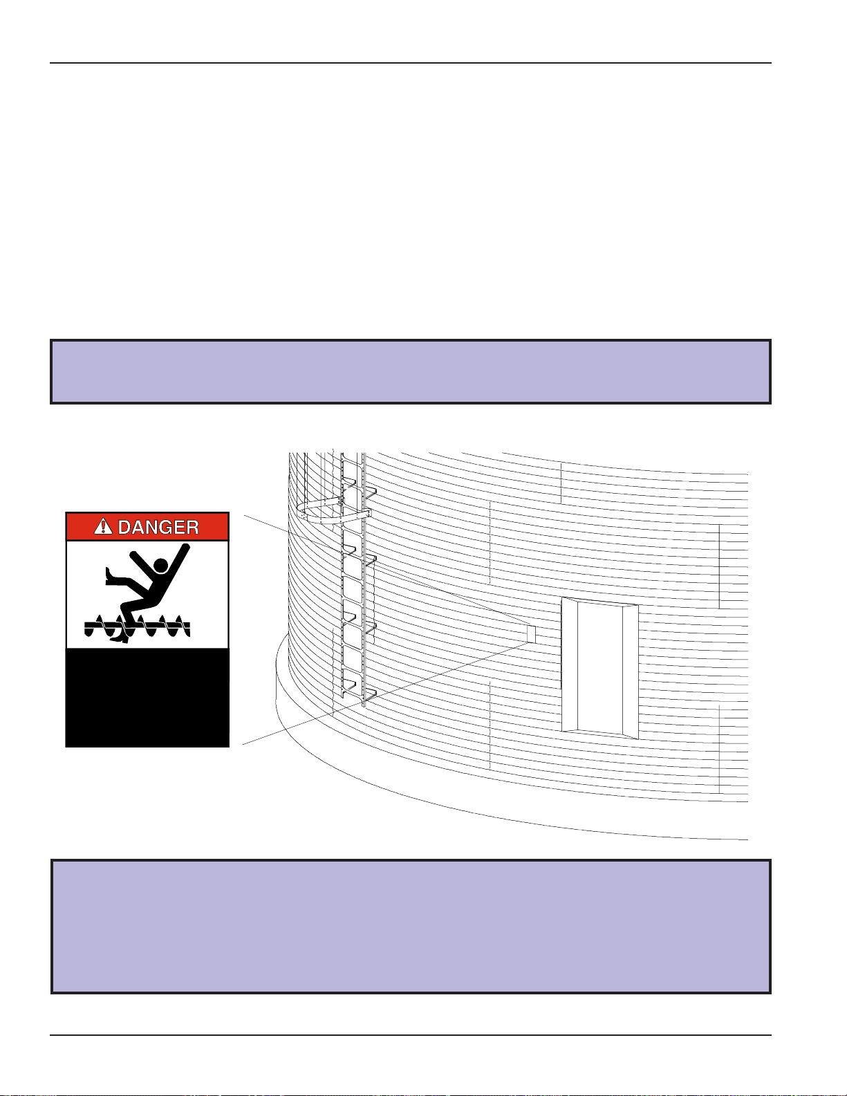
A. DANGER Sign No. DC-1395 was supplied with your bin unloading equipment. This safety sign
should be applied to the side of the bin near the bin opening, so it will be viewed by
people entering into the bin storage building. Do not cover any safety signs or any other
signs that are already there.
B. If the safety sign location suggested is not in full view because of equipment modifications, other
equipment in the area or any reason, then locate the safety sign in a more suitable location.
C. Be certain the surface is clean, dry and free of dirt and oil. Peel paper backing from decals and
stick into place. The adhesive backing will bond on contact.
KEEP CLEAR OF ALL AUGERS AND NEVER ENTER
FAILURE TO DO SO WILL RESULT IN
Please remember, safety signs provide important safety information for people
working near bin unloading equipment that is in operation.
ROTATING FLIGHTING!
THIS BIN IS EQUIPPED WITH GRAIN AUGERS
WHICH CAN KILL OR DISMEMBER.
THIS BIN UNLESS ALL POW ER IS
DISCONNECTED AND LOCKED OUT.
SERIOUS INJURY OR DEATH!
DC-1395
14 12" & 16" Series II Sweep PNEG-720-G2
If the Safety Sign cannot be easily read for any reason or has been painted over,
replace it immediately.
Additional Safety Signs may be obtained free of charge from your dealer, distributor
or ordered from the factory.
Order SAFETY SIGN NO. DC-1395
Page 15
Safety
ploy
)
OPERATOR QUALIFICATIONS.
A. The User/Operator must be competent and experienced to operate auger equipment. Anyone who
works with or around augers must have good common sense in order to be qualified. These
persons must also know and meet all other qualifications, such as:
1. Any person who has not read and/or does not understand all operation and safety instructions is
not qualified to operate any auger systems.
2. Certain regulations apply to personnel operating power machinery. Personnel under the age of
18 years may not operate power machinery , including augers. It is your responsibility, as owner
and/or supervisor, to know what these regulations are in your area or situation.
3. Unqualified or incompetent persons are to remain out of work area.
4. O.S.H.A. (Occupational Safety & Health Administration) regulations state: “At the time of initial
assignment and at least annually thereafter, the employer shall instruct every employee in the
safe operation and servicing of all equipment with which the employee is, or will be involved.”
(Federal Occupational Safety & Health Standards for Agriculture. Sub p art D, Section 19287.57
(a) (6).
B. As a requirement of OSHA, it is necessary for the employer to train the employee in the safe operat-
ing and safety procedures for this auger. W e included this sign-off sheet for your convenience and
personal record keeping. All unqualified people are to st ay out of the work area at all times. It is
strongly recommended that another qualified person who knows the shutdown procedure is in the
area in the event of an emergency . A person who has not read this manual and understands all
operating and safety instructions, is not qualified to operate the machine.
Date Em p loyees Signature
Em
1
2
3
4
5
6
7
8
9
10
11
12
13
14
15
16
17
18
19
20
21
22
23
24
25
ees Nam e (printed
PNEG-720-G2 12" & 16" Series II Sweep
15
Page 16
General Product Information
1. PRODUCT INFORMATION
Attention! This Series 2 Sweep is a single pass sweep. Consult the manufacturer of
your storage tank regarding the requirements or restrictions of the sweeping process.
The manufacturer may require a multiple pass sweep.
A. The Series 2 Sweep includes the following components:
- control panel
- two (2) motors
- motor covers
- motor mount
- auger flighting
- auger backshield assembly
- jack supports
B. The unit will operate only in a round grain bin equipped with a center sump in the bin floor.
NEVER enter a grain bin unless ALL power driven equipment has been shut down.
Disconnect and lockout power before entering the bin or servicing the equipment.
2. GENERAL INFORMATION.
A. GSI reserves the right to improve its product whenever possible and practical to do so. We reserve
the right to change, improve and modify products at any time without obligation to make changes,
improvements and modifications on equipment sold previously.
B. This new bin sweep auger has been engineered and manufactured to give years of dependable
service. The care and maintenance of this equipment will affect the satisfaction and service obtained. By following the instructions and suggestions recommended, the owner should receive
quality service for many years. If additional information or assistance should be required, please
contact GSI.
C. It is important to check both the quantity of parts and their descriptions with the packing list enclosed
within each package. All claims for freight damage or shortage must be made by the consignee
within ten (10) days from the date of the occurrence of freight damage. The consignee should
accept the shipment after noting the damage or loss.
16 12" & 16" Series II Sweep PNEG-720-G2
Page 17
General Product Information
2. GENERAL INFORMATION (CONT. )
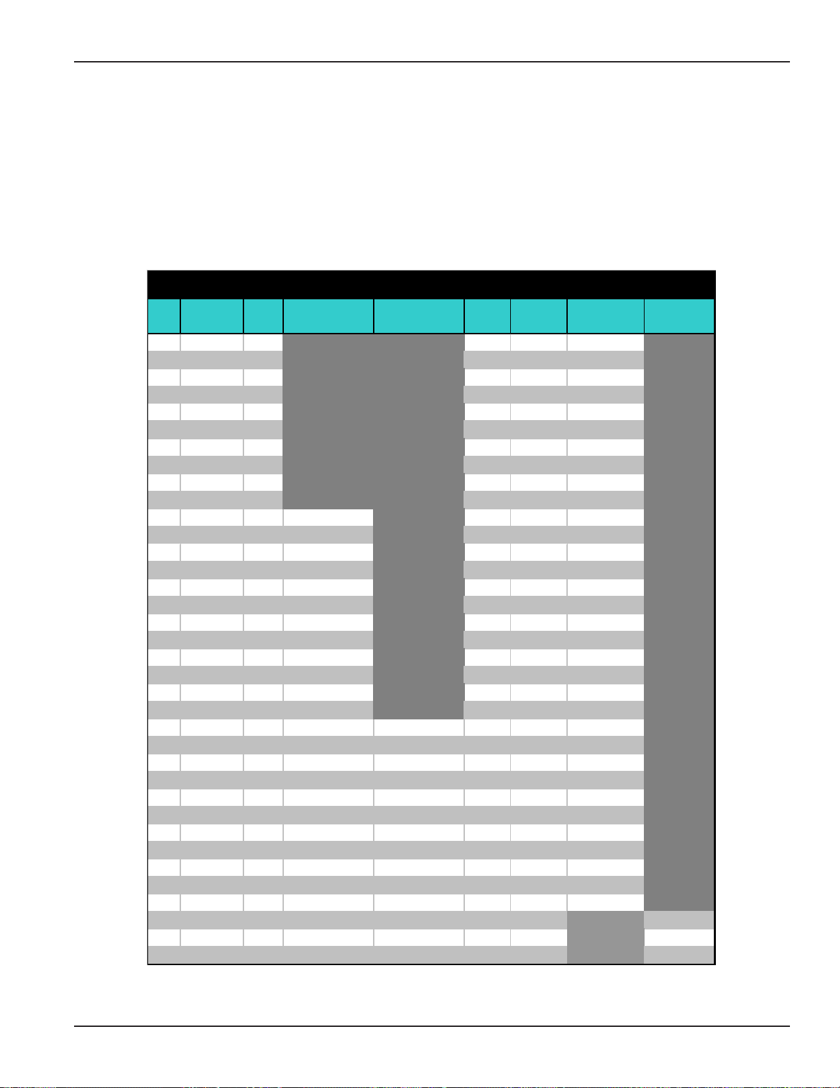
D. The chart below shows radius dimensions locating the points of contact between the sweep and
the bin floor . The dimensions may be used to figure material quantities of track to support the
sweep across the aeration flooring. The track material is not supplied with the sweep and must be
supplied by the installer. The dimensions are approximate and the assembled sweep should be
checked for exact point of contact.
RADIUS DIMENSIONS
Bin Inside Outside End Caster
Dia. Sections Head Inte rm ediate Intermediate Tire Tire 16" Only Extension
36' 2 36'' 109'' 139'' 198''
37' 2 44'' 121'' 151'' 210''
39' 2 52'' 133'' 163'' 222''
40' 2 52'' 133'' 163'' 222''
42' 2 60'' 145'' 175'' 234''
43' 2 64'' 157'' 187'' 246''
45' 2 64'' 157'' 187'' 246''
48' 2 84'' 181'' 211'' 270''
49' 2 84'' 181'' 211'' 270''
51' 2 92'' 193'' 223'' 282''
54' 3 64'' 144'' 217'' 247'' 306''
55' 3 64'' 144'' 217'' 247'' 306''
57' 3 76'' 156'' 229'' 259'' 318''
59' 3 84'' 168'' 241'' 271'' 330''
60' 3 92'' 180'' 253'' 283'' 342''
62' 3 92'' 188'' 265'' 295'' 354''
63' 3 92'' 188'' 265'' 295'' 354''
66' 3 92'' 204'' 289'' 319'' 378''
68' 3 92'' 212'' 301'' 331'' 390''
69' 3 92'' 212'' 301'' 331'' 390''
72' 3 92'' 228'' 325'' 355'' 414''
75' 3 92'' 236'' 337'' 367'' 426''
78' 4 92'' 212'' 288'' 361'' 391'' 450''
80' 4 92'' 220'' 300'' 373'' 403'' 462''
81' 4 92'' 220'' 300'' 373'' 403'' 462''
84' 4 92'' 236'' 324'' 397'' 427'' 486''
87' 4 92'' 236'' 332'' 409'' 439'' 498''
88' 4 92'' 236'' 340'' 421'' 451'' 510''
90' 4 92'' 236'' 348'' 433'' 463'' 522''
91' 4 92'' 236'' 348'' 433'' 463'' 522''
92' 4 92'' 236'' 356'' 445'' 475'' 534''
95' 4 92'' 236'' 364'' 457'' 487'' 546''
98' 4 92'' 236'' 380'' 481'' 511'' 570''
105' 5 92'' 236'' 372'' 469'' 499'' 608''
113' 5 92'' 236'' 380'' 481'' 511'' 656''
120' 5 92'' 236'' 380'' 481'' 511'' 704''
PNEG-720-G2 12" & 16" Series II Sweep
17
Page 18
General Product Information
3. CAPACITIES AND SPECIFICATIONS
Electrical controls and wiring should be installed by a qualified electrician. The motor
disconnect switches and conductor cables should comply with the National Electrical
code and any local codes which apply. Reset and motor starting stations should be
located so the operator can see that all personnel are clear of the equipment.
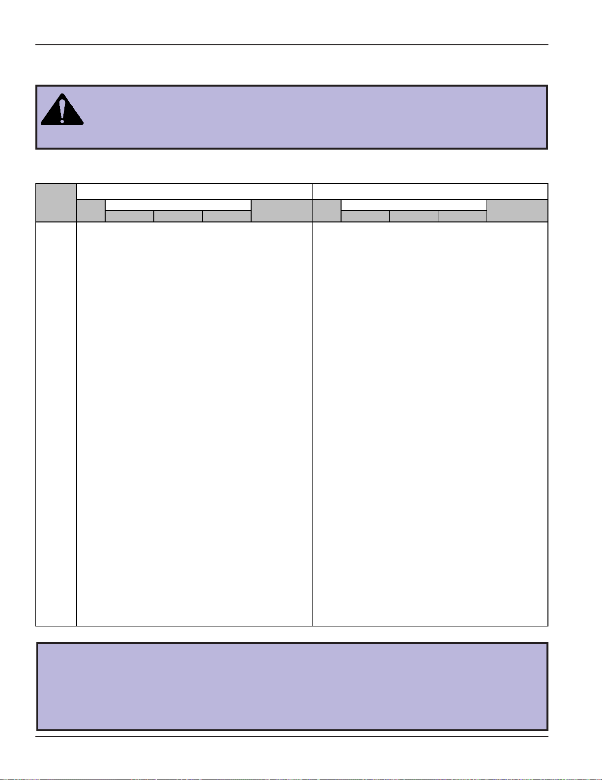
A. Use the chart below to determine the horsepower required.
12" SERI ES I I SWEEP 16" SERI ES I I SWE EP
Bin Drive Length Drive Length
Diameter H.P. 5000/125 6000/155 7000/180 Pivo t to End H.P. 8000/205 9000/230 10000/255 Pivot to End
36' 1 7.5 7.5 7.5 16.79' (5.12m) 2 7.5 7.5 7.5 16.85' (5.14m)
37' 1 7.5 7.5 7.5 17.79' (5.43m) 2 7.5 7.5 7.5 16.85' (5.14m)
39' 1 7.5 7.5 7.5 18.79' (5.73m) 2 7.5 7.5 7.5 17.85' (5.44m)
40' 1 7.5 7.5 7.5 18.79' (5.73m) 2 7.5 7.5 7.5 18.75' (5.72m)
42' 1 7.5 7.5 7.5 19.79' (6.04m) 2 7.5 7.5 10 19.85' (6.05m)
43' 1 7.5 7.5 7.5 20.79' (6.34m) 2 7.5 7.5 10 19.85' (6.05m)
45' 1 7.5 7.5 7.5 20.79' (6.34m) 2 7.5 7.5 10 20.85' (6.36m)
48' 1 7.5 7.5 7.5 22.79' (6.95m) 2 7.5 10 10 22.85' (6.96m)
49' 1 7.5 7.5 7.5 22.79' (6.95m) 2 7.5 10 10 22.85' (6.96m)
51' 1 7.5 7.5 10 23.79' (7.26m) 2 7.5 10 10 23.85' (7.27m)
54' 1 7.5 7.5 10 25.79' (7.86m) 2 10 10 10 25.85' (7.88m)
55' 1 7.5 7.5 10 25.79' (7.86m) 2 10 10 10 25.85' (7.88m)
57' 1 7.5 7.5 10 26.79' (8.17m) 2 10 10 10 26.85' (8.18m)
59' 1 7.5 7.5 10 27.79' (8.47m) 2 10 10 15 27.85' (8.49m)
60' 1 7.5 7.5 10 28.79' (8.78m) 2 10 10 15 28.85' (8.79m)
62' 2 7.5 7.5 10 29.79' (9.08m) 2 10 10 15 29.85' (9.10m)
63' 2 7.5 7.5 10 29.79' (9.08m) 2 10 10 15 29.85' (9.10m)
66' 2 7.5 7.5 10 31.79' (9.69m) 2 10 15 15 31.85' (9.71m)
68' 2 7.5 7.5 10 32.79' (10.00m) 2 10 15 15 32. 85' (10.01m)
69' 2 7.5 7.5 10 32.79' (10.00m) 2 10 15 15 32. 85' (10.01m)
72' 2 7.5 7.5 10 34.79' (10.61m) 2 15 15 15 34. 85' (10.62m)
75' 2 10 10 10 35.79' (10.91m) 2 15 15 15 35.85' (10.93m)
78' 2 10 10 10 37.79' (11.52m) 2 15 15 15 37.85' (11.54m)
80' 2 10 10 10 38.79' (11.83m) 2 15 15 15 38.85' (11.84m)
81' 2 10 10 10 38.79' (11.83m) 2 15 15 15 38.85' (11.84m)
84' 2 10 10 15 40.79' (12.44m) 2 15 15 15 40.85' (12.45m)
87' 2 10 10 15 41.79' (12.74m) 2 15 15 20 41.85' (12.76m)
88' 2 10 10 15 42.79' (13.05m) 2 15 15 20 42.85' (13.06m)
90' 2 10 10 15 43.79' (13.35m) 2 15 15 20 43.85' (13.37m)
91' 2 10 10 15 43.79' (13.35m) 2 15 15 20 43.85' (13.37m)
92' 2 10 10 15 44.79' (13.66m) 2 15 20 20 44.85' (13.67m)
95' 2 10 15 15 45.79' (13.97m) 2 15 20 20 45.85' (13.98m)
98' 2 10 15 15 47.79' (14.57m) 2 15 20 20 47.85' (14.58m)
105' 3 15 15 20 50.79' (15.48m) 3 20 20 20 50.85' (15.50m)
113' 3 15 15 20 54.79' (16.70m) 3 20 20 20 54.85' (16.72m)
120' 3 15 15 20 58.79' (17.92m) 3 20 20 20 58.85' (17.94m)
Due to continual improvements, GSI designs and specifications are subject to change without notice.
Bushel/MT Per Hour H orsepower Bushel/MT Per H our Horsepower
The horsepower recommendations are for augering reasonably dry grain. High moisture
grain (greater than 15%) will require greater power for maximum capacity. The maximum
capacity will be less with high moisture grain than with dry grain.
ALSO NOTE: Sweep drive and carrier wheels require plates or track over aeration flooring for travel and supports not supplied with the sweep unit. Contact your installer or
flooring provider for possible source and details.
18 12" & 16" Series II Sweep PNEG-720-G2
Page 19
General Product Information
3. CAPACITIES AND SPECIFICATIONS (CONT.)
B. A magnetic starter should be used to protect the motor when starting and stopping. It should stop
the motor in case of power interruption, conductor fault, low voltage, circuit interruption or motor
over load. The motor must be restarted manually. Some motors have built-in thermal overload
protection. If this is the type of motor being used, use only those with a manual reset.
C. The motor starting controls must be located outside the bin. They must NEVER be installed on the
Series II auger inside the bin.
D. Disconnect and lockout the power before resetting motor overloads.
E. Disconnect and lockout the power before entering the bin.
F. Disconnect and lockout the power before servicing the equipment.
G. Position the reset and motor starting controls so that the operators have full view of the equipment
There should ALWAYS be two (2) people in the work area.
H. Make sure electric motors are grounded.
A main power disconnect switch capable of being locked only in the OFF position should
be used. It should be locked whenever work is being done on the Series II Sweep.
PNEG-720-G2 12" & 16" Series II Sweep
19
Page 20

Assembly
1. BACK SHIELD ASSEMBLY
A. The sweep has been broken down into four(4) different section types. The head section,
intermediate section, tail, and extension section.
Use the charts below to determine the number of sections and the section sizes
required for the length of sweep to be used.
12" Series II Sweep Sections
Bin Dia. Sec. Head Int. Int. Int. Tail Ex t. Pivot to End
36' 2 52 149.5 16.79'
37' 2 64 149.5 17.79'
39' 2 76 149.5 18.79'
40' 2 76 149.5 18.79'
42' 2 88 149.5 19.79'
43' 2 100 149.5 20.79'
45' 2 100 149.5 20.79'
48' 2 124 149.5 22.79'
49' 2 124 149.5 22.79'
51' 2 136 149.5 23.79'
54' 3 100 60 149.5 25.79'
55' 3 100 60 149.5 25.79'
57' 3 112 60 149.5 26.79'
59' 3 124 60 149.5 27.79'
60' 3 136 60 149.5 28.79'
62' 3 136 72 149.5 29.79'
63' 3 136 72 149.5 29.79'
66' 3 136 96 149.5 31.79'
68' 3 136 108 149.5 32.79'
69' 3 136 108 149.5 32.79'
72' 3 136 132 149.5 34.79'
75' 4 136 144 60 149.5 40.79'
78' 4 136 108 60 149.5 37.79'
80' 4 136 120 60 149.5 38.79'
81' 4 136 120 60 149.5 38.79'
84' 4 136 144 60 149.5 40.79'
87' 4 136 144 72 149.5 41.79'
88' 4 136 144 84 149.5 42.79'
90' 4 136 144 96 149.5 43.79'
91' 4 136 144 96 149.5 43.79'
92' 4 136 144 108 149.5 44.79'
95' 4 136 144 120 149.5 45.79'
98' 4 136 144 144 149.5 47.79'
105' 5 136 144 132 144 53.5 50.79'
113' 5 136 144 144 144 89.5 54.79'
120' 5 136 144 144 144 137.5 58.79'
16" Series II Sweep Sections
Bin Dia . S ec. Head Int. Int. In t. Tai l Ext. P ivot to End
36' 2 52 150.25 16.85'
37' 2 52 150.25 16.85'
39' 2 64 150.25 17.85'
40' 2 76 150.25 18.85'
42' 2 88 150.25 19.85'
43' 2 88 150.25 19.85'
45' 2 100 150.25 20.85'
48' 2 124 150.25 22.85'
49' 2 124 150.25 22.85'
51' 2 136 150.25 23.85'
54' 3 100 60 150.25 25.85'
55' 3 100 60 150.25 25.85'
57' 3 112 60 150.25 26.85'
59' 3 124 60 150.25 27.85'
60' 3 136 60 150.25 28.85'
62' 3 136 72 150.25 29.85'
63' 3 136 72 150.25 29.85'
66' 3 136 96 150.25 31.85'
68' 3 136 108 150.25 32.85'
69' 3 136 108 150.25 32.85'
72' 3 136 132 150.25 34.85'
75' 4 136 144 60 150.25 40.85'
78' 4 136 108 60 150.25 37.85'
80' 4 136 120 60 150.25 38.85'
81' 4 136 120 60 150.25 38.85'
84' 4 136 144 60 150.25 40.85'
87' 4 136 144 72 150.25 41.85'
88' 4 136 144 84 150.25 42.85'
90' 4 136 144 96 150.25 43.85'
91' 4 136 144 96 150.25 43.85'
92' 4 136 144 108 150.25 44.85'
95' 4 136 144 120 150.25 45.85'
98' 4 136 144 144 150.25 47.85'
105' 5 136 144 132 144 54.25 50.85'
113' 5 136 144 144 144 90.25 54.85'
120' 5 136 144 144 144 138.25 58.85'
The section sizes are total length given in inches. The head section has 8" sub-
tracted from the shield length due to the pivot pipe location.
The 12" tail section has 5-1/2" added to the shield length due to the end shaft length.
The 16" tail section has 6-1/4" added to the shield length due to the end shaft length.
20 12" & 16" Series II Sweep PNEG-720-G2
Page 21
Assembly
1. BACK SHIELD ASSEMBLY (CONT.)
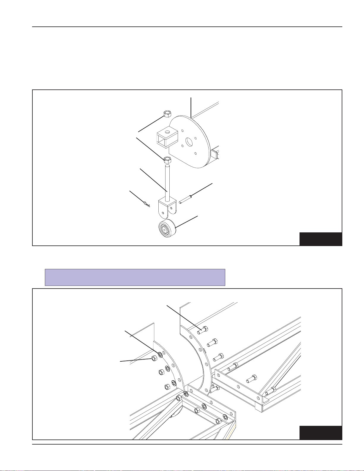
B. (All 16" Models and 12" Models with extensions) Assemble the caster assembly using the
1/2" x 3-1/2" clevis pin and 1/8" pin clip.
C. Attach the end caster assembly to the end of the tail section using two (2) 1"-8 hex nuts.
1"-8 hex nut
end caster assembly
1/2" x 3-1/2" clevis pin
1/8" pin clip
end caster
FIG. 1-C
D. Use eight (8) 5/8"-11 x 1-3/4" grade 8 hex bolts, lock washers, and hex nuts at each section connection.
The bolts MUST be inst alled as shown below.
5/8"-11 x 1-3/4" hex bolt
5/8" lockwasher
5/8"-11 hex nut
PNEG-720-G2 12" & 16" Series II Sweep
FIG. 1-D
21
Page 22
Assembly
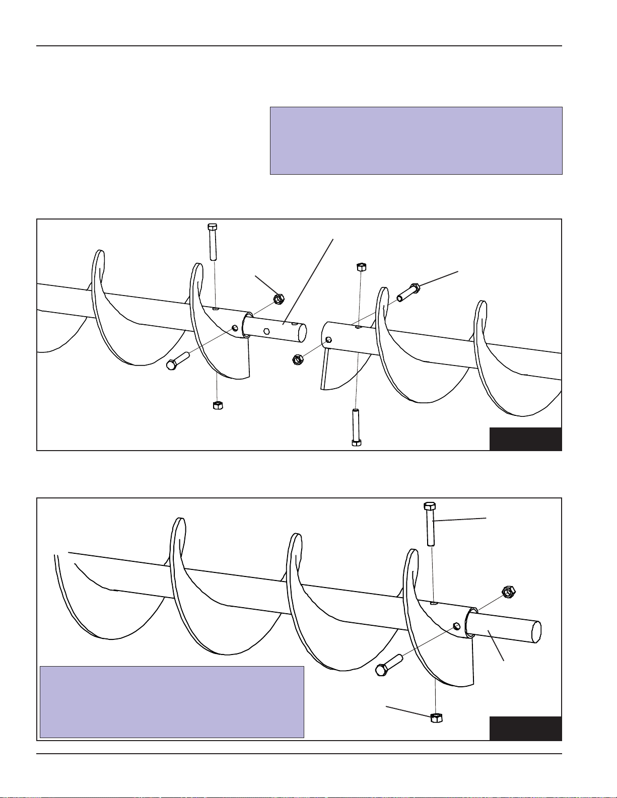
2. FLIGHTING ASSEMBLY
A. Layout the flight sections in order of
assembly starting with the head flight
working towards the tail flight.
B. Using the connecting stubs, bolt the
flight sections together with hex bolts
and lock nuts. Make sure the flight ends
are in time with each other .
lock nut
12" 2" x 11 1/2" Connecting Stub
Four (4) 5/8"-11 x 3 1/2" Hex Bolts
16" 3" x 13" Connecting Stub
Four (4) 3/4"-10 x 5 1/2" Hex Bolts
connecting stub
hex bolt
FIG. 2-B
C. Slide the end stub through the bearing plate on the tail section and into the tail flight securing it with hex
bolts and lock nuts.
hex
bolt
end
12" 2" x 12" End Stub
Two (2) 5/8"-11 x 3-1/2" Hex Bolts
16" 3" x 14 7/8" End Stub
Two (2) 3/4"-10 x 5-1/2" Hex Bolts
lock nut
stub
FIG. 2-C
22 12" & 16" Series II Sweep PNEG-720-G2
Page 23
3. HANGER BRACKET ASSEMBLY
A. Bolt the nylon bearings and hanger brack-
ets to the connecting stubs using hex bolts,
lockwashers, and hex nuts.
12" Two (2) 5/8"-11 x 2" Hex Bolts
16" Two (2) 1/2"-13 x 2 1/4" Hex Bolts
Assembly
hex bolt
hanger bracket
nylon bearing
connecting
stub
lockwasher
hex nut
B. Bolt the hanger brackets to the back
shields using two (2) 5/8"-1 1 x 2"
hex bolts, two (2) square washers, two
(2) lockwashers, and two (2) hex nuts.
5/8" lockwasher
square washer
square washer
FIG. 3-A
5/8"-1 1
hex nut
5/8"-11x 2"
hex bolt
PNEG-720-G2 12" & 16" Series II Sweep
5/8" lockwasher
5/8"-11 hex nut
FIG. 3-B
23
Page 24
Assembly
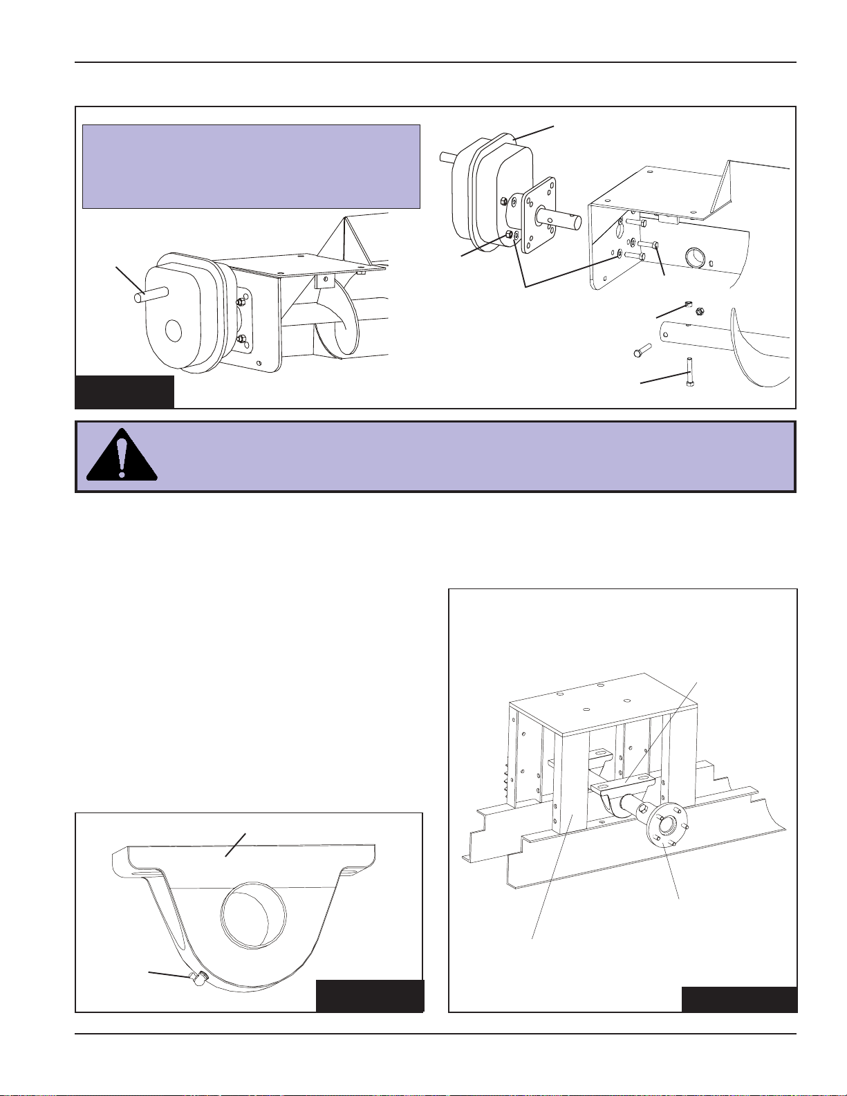
4. FLANGE BEARING ASSEMBLY
A. Slide the flange bearing onto the end stub and bolt it to the end plate using hex bolts, lockwashers,
and hex nuts.
12" Sweep 2" Flange Bearing
16" Sweep 3" Flange Bearing
Do not tighten the set screws on the bearing at this time. This can be done after
the gear reducer is installed.
Caster assembly only used on all 16" sweeps & 12" sweeps with
extensions.
Four (4) 1/2"-13 x 2-1/2" Hex Bolts
Four (4) 3/4"-10 x 3-1/2" Hex Bolts
(16" Shown.)
lockwasher
hex nut
5. GEAR REDUCER ASSEMBLY
A. Slide the output shaft of the reducer through the end plate of the head section and into the end of
the head flight and secure it the shafts with hex bolts and lock nuts. (See Figure 5)
hex bolt
flange bearing
FIG. 4
B. Bolt the reducer to the end plate of the head section using hex bolts, flat washers, & lockwashers,
24 12" & 16" Series II Sweep PNEG-720-G2
12" Two (2) 5/8"-11 x 3-1/2" Hex Bolts
16" Two (2) 3/4"-10 x 5-1/2" Hex Bolts
supplied with the reducer . (See Figure 5)
12" Four (4) 5/8"-11 x 2-1/2" Hex Bolts
16" Four (4) 3/4"-10 x 2-3/4" Hex Bolts
Page 25
5. GEAR REDUCER ASSEMBLY (CONT.)
The input shaft of the reducer MUST be to
the top of the reducer. Refer to the owner's
manual supplied with the reducer for proper
vent plug, fill plug, and drain plug locations.
input
shaft
hex nut
Assembly
gear reducer
flat washers
FIG. 5
The gear reducer is NOT filled with oil from the factory . For gear reducer
specifications and oil fill recommendations, refer to the lubrication section of
this manual.
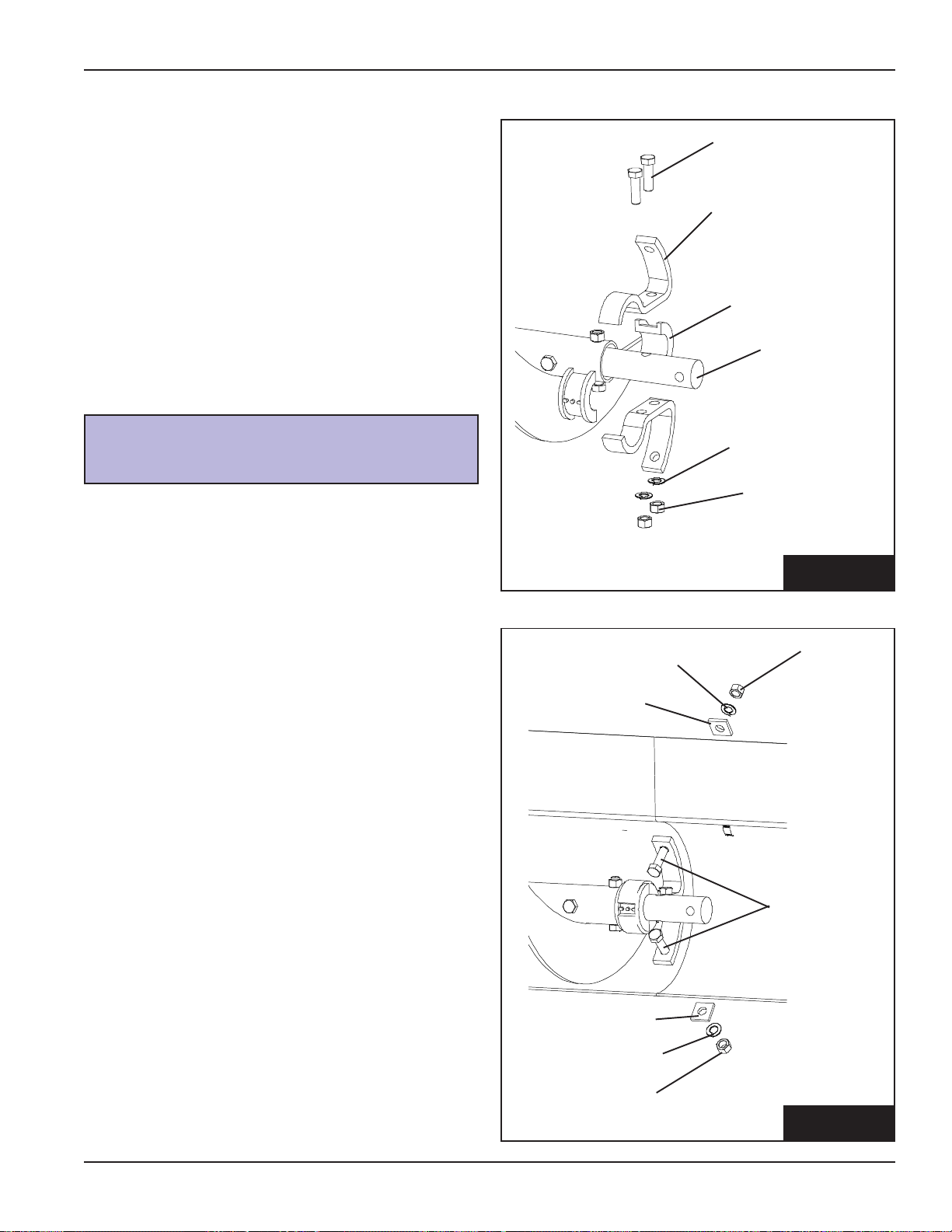
6. DRIVE AXLE ASSEMBLY & BEARING SUPPORT
A. Loosen set screws on bearings.
B. Replace standard grease zerks with 90°
grease zerks on both bearings. Make sure
the 90° grease zerk is turned as shown in Fig.
6-B, so the zerks are accessible from the
center of the tractor drive stand.
hex bolt
lock nut
hex bolt
Bearings
C. Slide the axle assembly between the legs of
the tractor drive stand as shown in Fig 6-C.
Bearing
90°
Grease
Zerk
PNEG-720-G2 12" & 16" Series II Sweep
FIG. 6-B
Axle Assembly
Tractor Drive
Stand Legs
FIG. 6-C
25
Page 26
Assembly
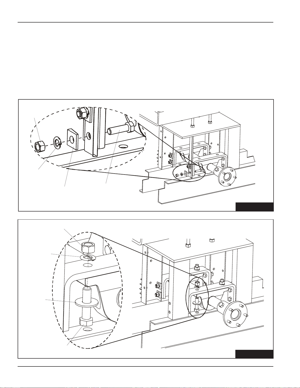
6. DRIVE AXLE ASSEMBLY & BEARING SUPPORT (CONT.)
D. Rotate the pillow block bearings until the bases
are facing up. (See Fig 6-C)
E. Bolt the bearing support brackets to the legs of
the tractor drive stand using ½" x 1 ¾" bolts,
½" lock washers, ½" bevel washers, and ½"
hex nuts. (See Fig. 6-E)
1/2" Hex
Nuts
1/2" Lock
Washers
1/2" Bevel
1/2" x 1-3/4" Bolts
Washers
F. Attach pillow block bearings to the bearing
brackets using 5/8" x 2 ½" bolts, 5/8" lock and
flat washers, and 5/8" hex nuts. (See Fig 6-F)
G. Tighten set screws on pillow block bearings.
H. Tighten all hardware.
5/8" Hex Nut
5/8" Lock
Washer
5/8" Flat
Washer
5/8" x 2-1/2" Bolt
FIG. 6-E
FIG. 6-F
26 12" & 16" Series II Sweep PNEG-720-G2
Page 27
Assembly
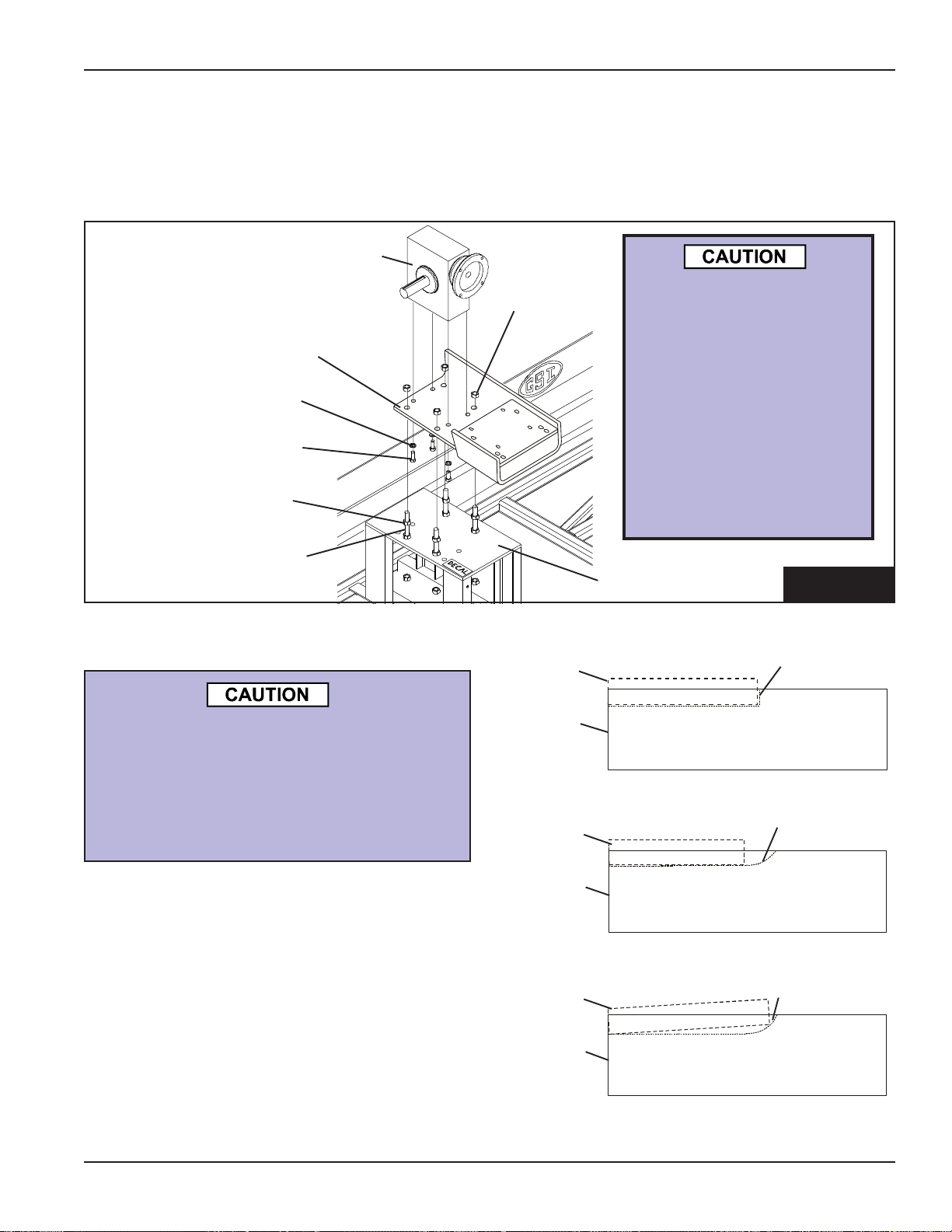
7. INSTALL REDUCER MOUNTING PLATE & REDUCER
A. Attach the C-Face reducer to the mounting plate using four (4) 1/2"-13 x 1-1/4" hex bolts and
lockwashers.
B. Fasten the mounting plate to the tail section plate using four (4) 5/8"-1 1 x 6" all-thread rods and
sixteen (16) hex nuts. Adjust the mounting plate as close as possible to the tail section plate.
C-Face Reducer
The gear reducer is NOT
hex nut
reducer
mounting plate
lockwasher
1/2"-13 x 1 1/4" hex bolt
hex nut
filled with oil from the
factory . For gear reducer specifications
and oil fill recommendations, refer to the owners manual supplied
with the reducer or the
lubrication information
in the maintenance
section of this manual.
5/8" x 6" all-thread rod
8-A. KEY ALIGNMENT
All keys should be parallel to the drive
shaft. If the key is not straight (parallel)
the gearbox quill sleave will crack.
THIS TYPE OF DAMAGE IS NOT
COVERED BY WARRANTY.
1. Place key in keyway on drive shaft.
2. Make sure key is flat (parallel to drive shaft) in
keyway as in Figure 8A-1 and 8A-2. NOT like
Figure 8A-3.
Key
Drive
Shaft
Key
Drive
Shaft
Key
tail section plate
FIG. 7
Keyway
FIGURE 8A-1
Key correctly positioned in a straight routed
keyway . (Profiled keyway)
Keyway
FIGURE 8A-2
Key correctly positioned in a scalloped
routed keyway. (Sled runner keyway)
Keyway
3. Line up keyway on shaft with keyway on reducer
and insert shaft into motor . (See Figure 8A-4 on
page 30.)
PNEG-720-G2 12" & 16" Series II Sweep
Drive
Shaft
FIGURE 8A-3
Key INCORRECTLY positioned in a
scalloped routed keyway. DO NOT install
key in this position.
27
Page 28
Assembly
Keyway on Reducer
Keyway on Drive Shaft
Key
FIGURE 8A-4
8-B. INSTALL TRACTOR DRIVE MOTOR
A. Bolt the C-Face motor to the reducer using hex bolt s, lockwashers, and a key .
(See note below for bolt size.)
56C Frame Four (4) 3/8"-16 x 1 1/4" Hex Bolts & 3/16" x 3/16" x 1" Key
143TC Frame Four (4) 3/8"-16 x 1 1/4" Hex Bolts & 3/16" x 3/16" x 1" Key
182TC Frame Four (4) 1/2"-13 x 1 1/4" Hex Bolts & 1/4" x 1/4" x 1" Key
key
C-Face Reducer
hex bolt
motor
lockwasher
FIG. 8-B
28 12" & 16" Series II Sweep PNEG-720-G2
Page 29
Assembly
9. GUARD ASSEMBLY
A. Slide the Chain Guard Top Seal (GC11978) over the Gear Reducer Output Shaf t before installing any
other components. Fig. TD1
Slide Seal on
Reducer Shaft
Before Installing
Upper Guard Plate
FIG. TD1
B. Attach the Guard Plate to the Tractor Drive Stand Legs using 3/8" bolts, lockwashers, and hex nuts
before attaching the Drive Sprocket (See Fig TD2)
C. Remove the Wheel Hub Assembly on the sprocket side only
Attach Guard Plate
to T ractor Drive
Stand Legs
Use 3/8"-16 Bolts, 3/8"-16 Lock
Washers and 3/8" Hex Nuts
Remove Wheel Hub
Assembly this Side Only
FIG. TD2
PNEG-1579 12" & 16" Series II Sweep Special
29
Page 30

Assembly
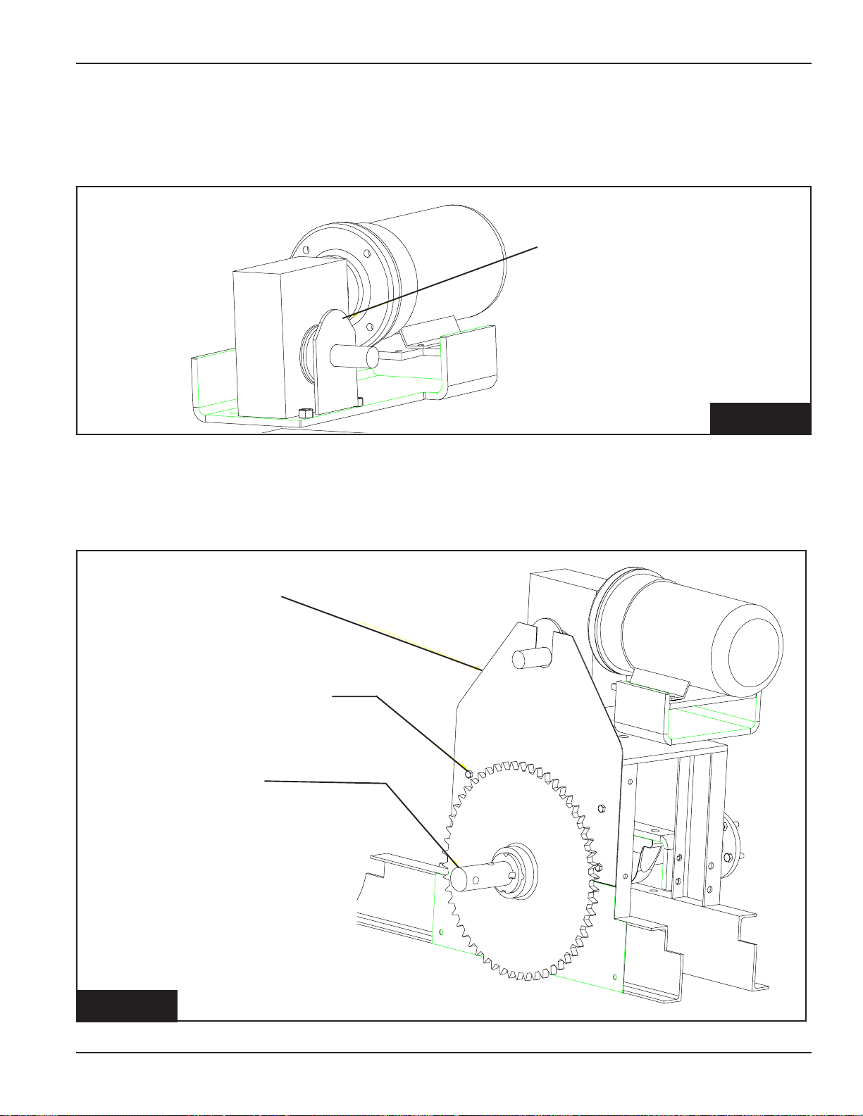
9. GUARD ASSEMBLY - (CONT.)
D. Slide the twelve tooth drive sprocket, bushing and key (see the key chart for your key size) onto the
output shaft of the reducer, making sure both sprockets line up. (See Fig TD3 & TD4)
Wedging forces in the bushing saw slot, such as that exerted by a narrow
edged regular screw driver, may damage or break the bushing. This damage
would not be covered under the GSI Warranty
Assemble 12 Tooth Sprocket,
Bushing and key to Gear Reducer
Output Shaft
To Assemble the Inner Lower Shaf t
Seal, this Sprocket and Bushing
May Have to be Loosened and
Moved Out of the Way
FIG. TD3
KEY CHART
1 HP - 5/16" x 2" Key
2 HP - 3/8" x 3-3/4" Key
3 HP - 3/8" x 3" Key
29-A
FIG. TD4
12" & 16" Series II Sweep Special PNEG-1579
Page 31

Assembly
9. GUARD ASSEMBLY - (CONT.)
E. Slide the Dust Seal Clips over the studs welded to the Guard Plate, capturing the Upper Shaft Seal.
F. Lock the Dust Seal Clips into position by tightening the 3/8 hex nuts.
Reducer not shown in this view. Removed for
Illustrational Purposes Only .
Slide Seal on Reducer Shaft
Before Installing Sprocket
Attach the Dust Seal Clips
with3/8 Hex Nuts
FIG. TD5
G. Attach the Inner Bottom Drive Shaf t Seal (GC11974) to the Guard Plate using 3/8-16 x 1 1/4" bolts, hex
nuts and flat washers. This seal is designed to fit tight around the Drive Axle Shaft. (See Figure TD6)
PNEG-1579 12" & 16" Series II Sweep Special
29-B
Page 32

Assembly
9. GUARD ASSEMBLY - (CONT.)
Attach the Inner
Bottom Drive Shaft
Seal to the Guard Plate
Use 3/8"-16 Bolts, Hex
Nuts, and Flat W ashers
for Attachment
FIG. TD6
G. Move the Bottom S procket back into position and lock in place. Make sure the sprockets are lined up
as in FIG TD4.
H. Install the Chain
Chain Tension-The chain should be installed fairly tight with only a small amount of slack. New chains
will loosen up slightly as the joints seat themselves, causing initial elongation. After the first operation, it
is advisable to tighten the chain.
I. Assemble the Bottom Chain Guard Trap to the Bottom Chain Guard Weldment using 1/2" x 3" HHCS
bolts, 1/2" split lock washers and 1/2" hex nuts
J. Attach the Bottom Chain Guard W eldment to the Tractor Drive St and using 3/8"-16 x 1 1/4" HHCS
bolts, 3/8" split lock washers and 3/8"-16 hex nuts.
29-C
12" & 16" Series II Sweep Special PNEG-1579
Page 33

9. GUARD ASSEMBLY - (CONT.)
Assembly
Bottom
Chain Guard
Weldment
1/2" x 3"
HHCS Bolt
Bottom Chain
FIG. TD7
K. Attach the Top Chain Guard (GC11984) to the T ractor Drive Stand using 3/8"-16 x 1" bolts, 3/8" split
lock washers and 3/8"-16 hex nuts.Attach the Top Chain Guard (GC1 1984) to the Tractor Drive Stand
using 3/8"-16 x 1" bolts, 3/8" split lock washers and 3/8"-16 hex nuts.
Guard Trap
3/8" x 1-1/4"
HHCS Bolt
1/2" Hex Nut
1/2" Split
Lock Washer
Top Chain Guard
Assembly (GC1 1984)
Bottom Chain Guard
Weldment (GC1 1991)
FIG. TD8
PNEG-1579 12" & 16" Series II Sweep Special
3/8"-16 x
1-1/4" bolt,
lock
washer,
and 3/8"
hex nut
29-D
Page 34

Assembly
9. GUARD ASSEMBLY - (CONT.)
L. Reinstall the Wheel Hub Assembly that was removed during step #C above. Leave the inner bolt out
until after the seals are put into place.
M. Slide the Inner Bottom Drive Shaft Seal (GC1 1986) halves over the studs welded to the Top Chain
Guard.
N. Slide the Outer Bottom Drive Shaft Seal (GC11985) halves over the studs welded to the Top Chain
Guard and on top of the Inner Bottom Drive Shaft Seal halves.
O. Lock the Bottom Drive Shaft Seals into position using 3/8" flat washers and 3/8"-16 hex nuts.
Install the Inner
Drive Shaft Seal
(Large Hole) First
Install the Outer
Drive Shaft Seal
(Smaller Hole)
on T op of the
Inner Seal
Lock into
position with
3/8" washers
and 3/8"-16
hex nuts
Reinstall wheel
hub assembly
FIG. TD9
29-E
12" & 16" Series II Sweep Special PNEG-1579
Page 35

NOTES
Assembly
PNEG-1579 12" & 16" Series II Sweep Special
29-F
Page 36

Assembly
10. TRACTOR WHEEL ASSEMBLY
A. Assemble the tires to the drive axle assembly using ten (10) 7/16" lockwashers, and hex nuts.
(See Fig 10)
NOTE: Tires go on backwards as shown.
Rotation
Direction
of Tires
7/16"
lockwashers
drive axle
7/16" hex nuts
FIG. 10
30 12" & 16" Series II Sweep PNEG-720-G2
Page 37

Assembly
11-A. COUNTER WEIGHT PLACEMENT
A. Place the equal number of counter weights each side of the drive assembly on the six inch (6")
channels that are welded to the tail section.
Caution! Use proper lifting procedures and equipment when lifting counter weights
(175 pounds each).
PNEG-720-G2 12" & 16" Series II Sweep
counter
weight
6" channels
FIG. 11-A
31
Page 38

Assembly
11-B. CHANNEL EXTENSION KIT FOR SWEEPS USED IN 72' DIA.
BINS & LARGER
A. 72' sweeps and larger need an extension kit installed.
B. Attach the center weight weldments to the adjustable center weight channel using eight (8) 1/2" x
1-1/4" bolts, split lockwashers, & hex nuts. The adjustable center weight has three sets of holes
for the center weight weldments so you can adjust the weights accordingly. (See Fig. 11-B1)
C. Place assembly on top of the back tail section, around the tires. The end of the adjustable center
weight should be placed under the tail frame. (See Fig. 11-B2)
D. Fasten assembly to tail section using two (2) 3/8" x 2-7/16" u-bolts, four (4) 3/8" lockwashers, &
four (4) 3/8" hex nuts.
T ail Frame
Center Weight
Weldment
Adjustable Center
Weight Channel
U-Bolts
FIG. 11-B1
Center Weight Weldment
U-Bolts
T ail Frame
32 12" & 16" Series II Sweep PNEG-720-G2
Adjustable Center
Weight Channel
FIG. 11-B2
Page 39

Assembly
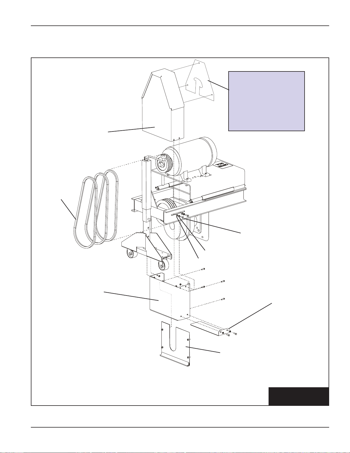
12. MOTOR JACK AND BASE ASSEMBLY
A. Attach the Motor Mount Base Assembly to the Head Section using four (4) 3/4"x 2"bolts, lock washers
and hex nuts. (See Fig 12)
B. Attach the Motor Jack Assembly to the Motor Mount Base Assembly using four (4) 1/2"-13 x 1-1/2" bolts,
1/2" flat washers and 1/2" hex nuts.
1/2" x 1-1/2"
bolts
1/2" flat washer
1/2" hex nuts
Motor Jack
Assembly
Motor Mount
Base Assembly
3/4" x 2" bolts
Head Section
PNEG-720-G2 12" & 16" Series II Sweep
3/4" lock washer
3/4" hex nuts
FIG. 12
33
Page 40

Assembly
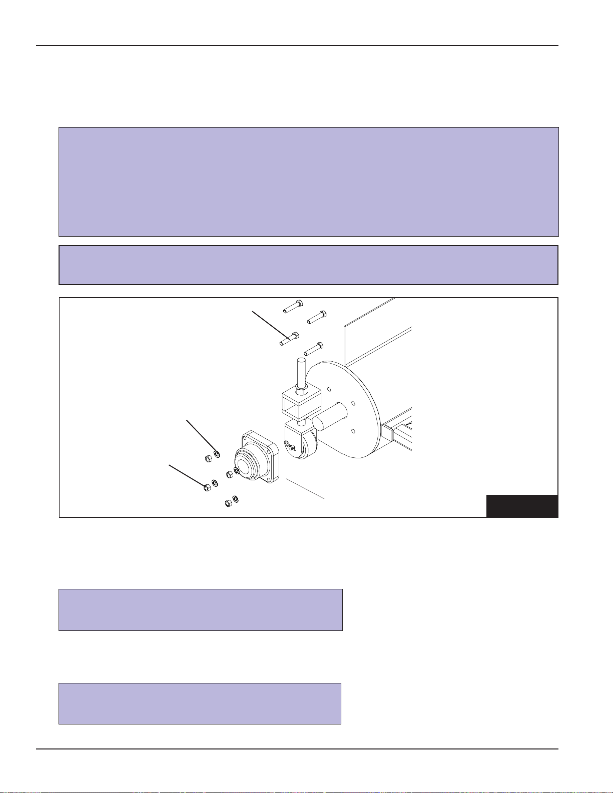
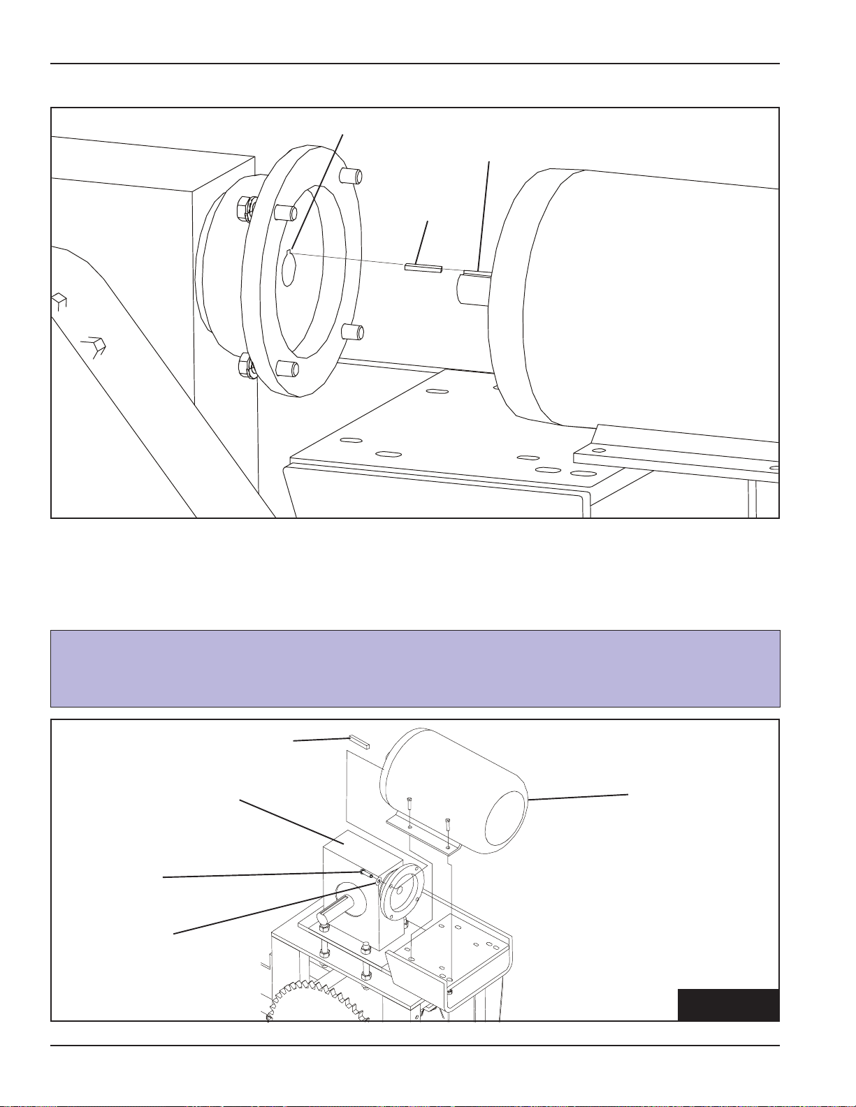
13. MOTOR INSTALLATION
A. Level the T op Plate Assembly by adjusting
the 1" nuts and washers on the adjustment
rods. (See Fig 13)
B. Line up the end face of the shafts as closely
as possible before bolting motor to mounting plate. (See Fig 13-A)
C. Fasten the motor to the motor mount using
hex bolts, lockwashers, and hex nuts.
(See Motor Bolt Chart for bolt sizes.)
Motor Bolt Chart
Mot or Size Hex Bolt Si ze Qt y.
213T 3/8"-16 x 1-1/ 4" 4
215T 3/8"-16 x 1-1/ 4" 4
254T 1/2"-13 x 1-3/ 4" 4
256T 1/2"-13 x 1-3/ 4" 4
284T 1/2"-13 x 1-3/ 4" 4
286T 1/2"-13 x 1-3/ 4" 4
Top Plate
Assembly
motor
motor bolt
(see chart
for size)
Line Up
Face of
Shafts
BEFORE
bolting
motor.
adjustment rod
1" hex nut
1" flat
washer
FIG. 13-A
FIG. 13
34 12" & 16" Series II Sweep PNEG-720-G2
Page 41

Assembly
13. MOTOR INSTALLATION - (CONT.)
D. Insert the upper belt guard seal (Slider) GC12024 into the track on the belt guard fill plate (GC12023.)
Insert Slider (GC12024) into
track on belt guard fill plate
assembly (GC12023)
FIG. 13D
E. Install the Slider/fill plate assembly over the motor shaft before mounting the motor
sheave and bushing.
The slider and the fill plate
assembly fit over motor
shaft as shown
FIG. 13E
PNEG-1579 12" & 16" Series II Sweep Special
34-A
Page 42

Assembly
NOTES
34-B
12" & 16" Series II Sweep Special PNEG-1579
Page 43

Assembly
14. SHEAVE INSTALLATION
Warning! To ensure that the drive is not unexpectedly started, turn off and
lock out or tag out the power source before proceeding. Failure to observe
these precautions could result in bodily injury .
A. Loosely bolt the bushing and large sheave together with the screws provided with the bushing.
B. Slide the bushing and large sheave onto the auger gear reducer input shaft with a key . (See Fig. 14-A)
Wedging forces in the bushing saw
slot, such as that exerted by a
narrow edged regular screw driver ,
may damage or break the bushing.
This damage would not be covered
under the GSI warranty .
key
bushing
large sheave
input shaft
FIG. 14-A
C. Loosely bolt the bushing and small sheave together with the screws provided with the bushing.
D. Slide the bushing and small sheave onto the motor shaft with a key. (See Fig. 14-B)
output shaft
key
bushing
small sheave
PNEG-720-G2 12" & 16" Series II Sweep
FIG. 14-B
35
Page 44

Assembly
14. SHEAVE INSTALLATION (cont.)
E. Align the sheaves with a straight edge to assure proper alignment and tighten the screws
on the bushings.
F. Carefully install the belts.
Adjust the all-thread nuts on the motor mount to attain correct belt tension while
making sure the motor mount is level on both rods. This will also affect sheave
alignment.
G. Assemble the bottom belt guard assembly. Attach the belt guard back plate assembly (GC12028) to
the belt guard bottom shell assembly (GC09764) using 3/8-16 x 1 HHCS and 3/8 lock washers.
Belt guard bottom
shell assembly
Bottom belt
guard bottom
plate
Bottom belt
guard back
plate assembly
36
FIG. 14G
12" & 16" Series II Sweep Special PNEG-1579
Page 45

Assembly
14. SHEAVE INSTALLATION (cont.)
H. Attach the bottom belt guard assembly to the motor mount frame with 3/8-16 x 1 HHCS, 3/8 flat
washers and 3/8 lock washers. Do not tighten the 3/8 HHCS as the assembly will be adjusted after
the top cover is attached.
Sheave, bushing
and belts not
shown for clarity
Loosely attach the
bottom belt guard
assembly to the
motor mount frame
with 3/8"-16 x 1
HHCS, 3/8" flat
washers and 3/8"
lock washers
I . Attach both the bottom belt guard seals (GC12026 an GC12027) around the reducer shaft and to the
bottom belt guard assembly using 3/8-16 x 1 HHCS, 3/8 flat washers and 3/8 lock washers.
Do not tighten these
bolts until the belt
guard top assembly
is mounted.
FIG. 14H
Attach both belt guard
bottom seals to the bottom
belt guard assembly
Attach using 3/8"-16 x 1"
HHCS, 3/8" flat washers
and 3/8" lock washers
PNEG-1579 12" & 16" Series II Sweep Special
FIG. 14I
36-A
Page 46

Assembly
14. SHEAVE INSTALLATION (cont.)
J. Slide the belt guard top assembly over the lower belt guard assembly attachment bolts. Att ach the
belt guard top assembly to the fill plate using 3/8-16 x 1 HHCS, 3/8 flat washers and 3/8 lock washers. Slide the complete belt guard assembly as close to the motor as possible without allowing the
sheaves or the belt to rub the steel guard. Tighten the belt guard attachment bolt s.
Slide belt guard top
assembly over lower belt
guard assembly
attachment bolts
Attach the top belt assembly
to the belt guard fill plate
assembly with 3/8"-16 x 1"
HHCS, 3/8" flat washers
and 3/8" lock washers
Slide the belt guard as close to
motor as possible without
allowing sheaves or belt to rub
front of guard. Tighten the bolts.
FIG. 14J
36-B
12" & 16" Series II Sweep Special PNEG-1579
Page 47
14. SHEAVE INSTALLATION (cont.)
top belt guard
Assembly
This is a guard plate
made specific for
your motor size.
Attach using 3/8"
bolts, washers, and
lock washers.
belts
bottom belt guard
3/8"-16 x 1" hex bolt
lockwasher
flat washer
Belt Guard
Bottom Pan
Belt Guard
Bottom Back
Plate
PNEG-1579 12" & 16" Series II Sweep Special
FIG. 14K
36-C
Page 48

Assembly
NOTES
36-D
12" & 16" Series II Sweep Special PNEG-1579
Page 49

15. ELECTRICAL ASSEMBLY
Caution! All electrical wiring and service work must be performed by a qualified
electrician and must meet all State and Local electrical codes.
Assembly
A. Place the 3/4" rigid conduit in order starting with the head section
and working towards the tail or extension section.
B. Connect the rigid conduit together using one (1) 3/4" conduit
coupling between each piece of conduit.
See the chart for the correct size of conduit to the corresponding sweep size.
FIG. 15-B
3/4" rigid
conduit
3/4" conduit
coupling
3/4" rigid
conduit
Sweep Section Conduit Sizes
Bin 10' Conduit Other
Diameter Pieces Pieces
36' N/A 1 @ 9'
37' 1 N/A
39'-40' 1 1 @ 1'
42' 1 1 @ 2'
43'-45' 1 1 @ 3'
48'-49' 1 1 @ 5'
51' 1 1 @ 6'
54'-55' 1 1 @ 8'
57' 1 1 @ 9'
59' 2 N/A
60' 2 1 @ 1'
62'-63' 2 1 @ 2'
66' 2 1 @ 4'
68'-69' 2 1 @ 5'
72' 2 1 @ 7'
75' 2 1 @ 8'
78' 3 N/A
80'-81' 3 1 @ 1'
84' 3 1 @ 3'
87' 3 1 @ 4'
88' 3 1 @ 5'
90'-91' 3 1 @ 6'
92' 3 1 @ 7'
95' 3 1 @ 8'
98' 4 N/A
105' 3 1 @ 9'
113'-120' 4 N/A
PNEG-720-G2 12" & 16" Series II Sweep
37
Page 50

Assembly
15. ELECTRICAL ASSEMBLY (cont.)
C. Connect the 3/4" x 48" liquid-tight flex conduit to the drive end of the 3/4" rigid conduit
using one (1) 3/4" conduit coupling and one (1) 3/4" liquid-tight flex conduit coupling.
1. Thread a 3/4" conduit coupling onto the 3/4" rigid conduit.
2. Thread a 3/4" flex conduit coupling body onto the 3/4" conduit coupling.
3 Slide a 3/4" flex conduit coupling cap onto the 3/4" flex conduit followed by a plastic ring.
4. Thread a steel ring into the 3/4" flex conduit.
5. Thread the 3/4" flex conduit coupling cap onto the 3/4" flex conduit coupling body.
3/4" flex
conduit
steel ring
3/4" flex conduit
coupling body
3/4" flex conduit
coupling cap
3/4" conduit
coupling
plastic ring
3/4" rigid
conduit
FIG. 15-C
38 12" & 16" Series II Sweep PNEG-720-G2
Page 51

Assembly
15. ELECTRICAL ASSEMBLY (cont.)
D. Attach the 3/4" x 12" liquid-tight flex conduit to the other end of the rigid conduit using one (1) 3/4"
conduit coupling and one (1) 3/4" liquid-tight flex conduit coupling.
E Connect the two (2) junction boxes together using the 1" x 4 3/4" conduit nipple.
F. Connect the 3/4" x 12" liquid-tight flex conduit to the left junction box using one (1) 3/4" liquid-tight
flex conduit coupling and one (1) 1" to 3/4" reducer bushing.
G. Attach the 3/4" x 40" liquid-tight flex conduit to the right junction box using one (1) 3/4" liquid-tight
flex conduit coupling and one (1) 1" to 3/4" reducer bushing.
3/4" flex conduit
coupling
right junction box
3/4" x 40"
flex conduit
1" to 3/4" reducer
bushing
reducer
bushing
1" x 4 3/4" conduit
3/4" flex conduit
3/4" x 12"
coupling
left junction box
flex conduit
H. Feed each of the six (6) 14 AWG stranded wires through the 3/4" rigid conduit assembly and cut
them off, leaving six inches (6") at both the left junction box and drive motor.
nipple
FIG. 15-G
I . Feed each of the six (6) 10 A WG stranded wires cord through the 3/4" x 40" liquid tight flex conduit
and cut four (4) of them off, leaving six inches (6") at both the right junction box and auger motor .
Cut the 10 A WG blue and yellow wires longer so they can be connected to the 14 AWG blue and
yellow wires in the left junction box.
PNEG-720-G2 12" & 16" Series II Sweep
39
Page 52

Assembly
15. ELECTRICAL ASSEMBLY (cont.)
J. Place the 3/4" rigid conduit assembly onto the back frame of the sweep between the connecting
angle and connecting flange.
3/4" rigid
conduit
connecting
flange
connecting
angle
FIG. 15-J
K. Fasten the junction boxes to the mounting plate using two (2) 3/8"-16 x 1 3/8" u-bolts, four (4)
lockwashers, and hex nuts.
junction box
3/8" x 1-3/8"
u-bolt
mounting
plate
lockwasher
hex nut
FIG. 15-K
40 12" & 16" Series II Sweep PNEG-720-G2
Page 53

Assembly
15. ELECTRICAL ASSEMBLY (cont.)
L. Attach the 3/4" rigid conduit assembly to the sweep using the 5/16"-18 x 3/4" studs welded to the
sweep using 1" conduit clamps, lockwashers, and hex nuts.
M . Run the 14 A WG stranded
wires into the drive motor
and fasten the 3/4" x 48"
liquid-tight flex conduit to the
motor using one (1) 3/4"
liquid-tight flex conduit
coupling. Some motors may
require a reducer bushing
not supplied with the sweep.
Connect the leads as required.
N. Run the 10 AWG stranded
wires into the auger motor
and fasten the 3/4" x 40"
liquid-tight flex conduit to the
motor using one (1) 3/4"
liquid-tight flex conduit
coupling. Some motors may
require a reducer bushing
not supplied with the sweep.
Connect the leads as required.
5/16" hex nut
5/16" lockwasher
1" conduit clamp
5/16"-18 x 3/4"
stud
3/4" rigid conduit
FIG. 15-L
O. Tractor Drive:
Slide a 5/8" to 3/4" cord connector six inches (6") onto one (1) end of the 14 AWG/4 wire cords and
fasten it to the junction box using one (1) 1" to 3/4" reducer bushings. Connect the leads as required.
Sweep Drive all 12" and 16" under 105 Model:
Slide a 5/8" to 3/4" cord connector six inches (6") onto one (1) end of the 10 AWG/4 wire cords and
fasten it to the junction box using one (1) 1" to 3/4" reducer bushings. Connect the leads as required.
Sweep Drive all 16" 105 Model and over:
Slide a 5/8" to 3/4" cord connector six inches (6") onto one (1) end of the 8 AWG/4 wire cords and
fasten it to the junction box using one (1) 1" to 3/4" reducer bushings. Connect the leads as required.
P. Slide a 1/2" to 5/8" cord connector six inches (6") onto the end of the 14 A WG/3 wire cord and
fasten it to the junction box using one (1) 1" to 3/4" reducer bushings. Connect the leads as
required.
Q. Use the plugs provided with the junction boxes to close the holes not being used.
PNEG-720-G2 12" & 16" Series II Sweep
If you are using the pivot kit, skip to page 47 and refer to step "17A".
41
Page 54

Assembly
15. ELECTRICAL ASSEMBLY (CONT.)
5/8" to 3/4" cord connector
for: 10 AWG/4 wire cord
(HBL2431SW)
3/4" to 7/8" cord connector
for: 8 A WG/4 wire cord
(HBL2431SW)
14 A WG/4 wire cord
(HBL2431SW)
14 A WG/3 wire cord
(CS8165C)
1" to 3/4"
reducer
bushing
1/2" to 5/8" cord
connector body
rubber
grommet
plastic
ring
1/2" to 5/8" cord
connector cap
FIG. 15-R
R. Assemble the cord plugs to the other end of each cord. The 14 AWG/4 wire cord requires the
"HBL2431SW" plug. The 10 AWG/4 and 8 AWG/4 wire cord requires the "CS8165C" plug. The
14 A WG/3 wire cord requires the "HBL2311SW" plug.
The plugs are different for each cord and MUST be assembled correctly. This is
done so the cords can not be plugged into the control panel incorrectly.
S. Mount the control panel outside the bin near the door .
The control panel MUST be mounted OUTSIDE the bin near the door. The
foot switch has to be plugged into the control panel and depressed before
the sweep is operational. It has a 10' cord so the sweep can only be monitored from OUTSIDE the bin.
42 12" & 16" Series II Sweep PNEG-720-G2
Page 55

16. JACK SUPPORT ASSEMBLY
Assembly
All Current Pr oduction and Old Style 12"
Jack Support (See fig. 16-A & 16-C)
A. Attach one (1) caster wheel to the jack caster
B. Locate the 2" x 2" x 12" tube to the right of each
C. Attach the jack caster assembly to the jack
D. Bolt the jack assembly to the jack mount as-
Be sure to use the spanner bushings, supplied with the caster wheels, between the
caster and the caster plate on each side. (12" Sweeps Only.)
assembly using one (1) 3/4" x 5-1/2" hex bolt,
lockwasher , and hex nut.
connecting angle and fasten the jack mount
assembly to the sweep frame using one (1) jack
mount plate, four (4) 1/2"-13 x 3-3/4" hex bolts,
lockwashers, and hex nuts.
assembly using one (1) pin.
sembly using four (4) 1/2"-13 x 2" hex bolts,
lockwashers, and hex nuts.
All Old Style 16" Jack Support (See fig.
16A & 16-C)
A. Attach one (1) caster wheel to the jack caster
assembly using one (1) 3/4" x 5-1/2" hex bolt,
lockwasher, and hex nut.
B. Locate the 2" x 2" x 12" tube to the right of each
connecting angle and fasten the jack mount
assembly to the sweep frame using one (1) jack
mount plate, four (4) 1/2"-13 x 3-3/4" hex bolts,
lockwashers, and hex nuts.
C. Attached 16" Jack Caster Assembly to the
swivel caster wheel using four (4) 1/2" x 1-1/2"
HHCS bolts, lockwashers, & hex nuts.
D. Attach the jack caster assembly to the jack
assembly using one (1) pin.
jack
assembly
1/2" x 2"
hex bolt
3/8" x 2 3/4"
safety snap pin
E. Bolt the jack assembly to the jack mount as-
sembly using four (4) 1/2"-13 x 2" hex bolts,
lockwashers, and hex nuts.
CURRENT PRODUCTION SWEEP SHOWN
Connecting
Angle
jack mount
assembly
Tubes cut away
for clarity .
jack mount
plate
1/2" x 3-3/4"
hex bolt
PNEG-720-G2 12" & 16" Series II Sweep
FIG. 16-C
43
Page 56

Assembly
FIG. 16-A
12" JACK SUPPORT
16" JACK SUPPORT
AFTER 11-01-04
jack assembly
1/2" x 1-1/2"
HHCS
jack truss
jack mount plate
jack mount
assembly
pin
3/4" x 5-1/2"
caster wheel
1/2" x 3-3/4" HHCS
sweep jack
caster
assembly
1/2" x 1-1/2"
HHCS
jack assembly
jack truss
1/2" x 3-3/4"
HHCS
jack mount
assembly
jack mount plate
pin
OLD STYLE 16"
JACK SUPPORT
BEFORE 11-01-04
44 12" & 16" Series II Sweep PNEG-720-G2
sweep jack
caster assembly
swivel
caster
Page 57

17. CENTER PIVOT INSTALLATION
Assembly
If you are only running the cords across the floor, you may skip step 17A and go
to step 17B.
A. Center Pivot With Pivot Kit
1. Use the pivot assembly supplied with the sweep pivot kit and cut it to fit, if needed.
The center pipe of the pivot assembly MUST be in the center of the bin. If it
is not, the sweep could hit the bin wall.
2. Feed the multi-conductor cord through the hole in the back of the sweep head section leaving
five feet (5') of cord outside the hole.
PNEG-720-G2 12" & 16" Series II Sweep
multi-conductor cord
(Leave 5' of cord outside of hole.)
FIG. 17-A2
45
Page 58

Assembly
17. CENTER PIVOT INSTALLATION (cont.)
3. Feed the power cord through the pivot tube.
4. Align the hole in the backshield with the pivot tube and push the sweep onto the pivot tube.
5. Connect the pivot plate to the backshield using two (2) 1/2"-13 x 1-3/4" hex bolts, flat washers,
lockwashers, and hex nuts.
6. Fasten the pivot rod to the backshield and pivot plate using two (2) 1/2"-13 x 2" hex bolts,
lockwashers, and hex nuts.
7. Screw the 45 degree grease fitting into the pivot assembly pipe.
1/2"-13 x 2" hex bolt
hex nut
lockwasher
1/2"-13 x 1 3/4" hex bolt
pivot rod
flat washer
pivot tube
pivot plate
cord
pivot assembly
45 degree
grease fitting
multi-conductor
cord
FIG. 17-A3
46 12" & 16" Series II Sweep PNEG-720-G2
Page 59

17. CENTER PIVOT INSTALLATION (cont.)
9. Connect the 1" x 48" liquid-tight flex conduit to the pivot tube using one (1) 1" conduit coupling and
one (1) 1" liquid-tight flex conduit coupling.
10. Connect the 1" x 48" liquid-tight flex conduit to one of the junction boxes using one (1) 1" liquidtight flex conduit coupling. Connect the leads as required.
Assembly
1" flex conduit
coupling
1" x 48" flex
pivot tube
conduit
1" conduit
coupling
11. The customer is to provide proper power cord protection between the pivot assembly and the
sump transition.
12. The multi-conductor power cord can be connected with the 14 AWG/3 wire, 14 AWG/4 wire, and
10 AWG/4 wire cords in an explosion proof junction box .
13. Use the plugs provided with the junction box to close the holes not being used.
14. Assemble the cord plugs to the other end of each of the cords. The 14 AWG/4 wire cord requires
the "HBL2431SW" plug. The 8AWG/4 & the 10 AWG/4 wire cord requires the "CS8165C" plug.
The 14 A WG/3 wire cord requires the "HBL2311SW" plug.
FIG. 17-A9
The plugs are different for each cord and MUST be assembled correctly. This
is done so the cords can not be plugged into the control panel incorrectly.
PNEG-720-G2 12" & 16" Series II Sweep
47
Page 60

Assembly
17. CENTER PIVOT INSTALLATION (cont.)
B. Center Pivot For Standard Sweep
The center pivot for a standard sweep must be supplied by the customer.
The following are requirements for installation.
The pivot pin MUST be in the center of the bin. If it is not, the sweep
could hit the bin wall.
1. The cross braces must be 1/2" steel plate.
2. The pivot pin must be 1-1/2" diameter steel bar and extend approximately 4" above floor
elevation.
18. CONTROL PANEL SETUP
The Series 2 Sweep is supplied with adjustable overlaods that are not set at the factory. These
should be set slightly higher than the full load amp (FLA) value listed on the motor nameplates.
A. Find the desired "High" amp and "Low" amp set points.
The bin must have grain in it to be able to properly program the control panel.
1. High Amp Set Point: The amp load the auger draws when the auger flighting is 90% loaded.
This will turn off the tractor drive motor . Initially, set the value to 90% of the Full Load Amps
(FLA) listed on the motor nameplate.
2. Low Amp Set Point: The amp load the auger motor draws the auger flighting 10% loaded.
This will turn on the drive motor . Initially, set this value to 10% over the amp draw of the sweep
running empty .
NEVER program the "High Amp Set Point" greater than the full load
running amps of the auger motor.
B. Programming the Amp Meter
1. Setting Input
a. Press "PRGM" to "inPut".
b. Press "ENTER".
c. Press "PRGM" to "i4-20".
d. Press "ENTER" to RUN MODE.
2. Setting Setup
a. Press "PRGM" to "SEtuP".
b. Press "ENTER" to "rdEC"
Use arrow buttons to change the decimal placement. Show .0 Amps.
c. Press "ENTER" to "SETLO"
d. Press "ENTER"
V alue = 0.0
e. Press "ENTER" to "SEtHi".
48 12" & 16" Series II Sweep PNEG-720-G2
Page 61

1 8 . CONTROL PANEL SETUP (CONT.)
f. Press "Enter"
V alue = 50
Use arrow buttons to change value.
g. Press "ENTER" to "LoCut".
This value = 0
h. Press "ENTER" to RUN MODE.
3. Setting Presets
a. Press "Pre A".
b. Press "PRGM"
This value = "High Amp Set Point".
Use arrow buttons to change value.
c. Press "ENTER".
4. Setting Relays
a. Press "PRGM" to "rELAYS".
b. Press "ENTER" to "HYS A".
c. Press "PRGM"
This value = "High Amp Set Point" - "Low Amp Set Point"
Use arrow buttons to change value.
d. Press "ENTER" to RUN MODE.
Assembly
EXAMPLE: Full Load Running Amps = 21 Amps
High Amp Set Point = 20 Amps
Low Amp Set Point = 12 Amps
Then "HYS A" = 8 Amps (NOTE: This is the dif ference between the High Amp Set Point
and the Low Amp Set Point. [20 Amps - 12 Amps = 8 Amps])
And "Pre A" = 20 Amps
C. Locking the Amp Meter
1. Locking the amp meter is not required, but does prevent the meter from being tampered with
once it is programmed.
2. In RUN MODE press "LOCK" three (3) times within five (5) seconds.
This value = A number that is easily remembered.
Use arrow buttons to change value.
a. Press "ENTER".
D. Unlocking the Amp Meter
1. In RUN MODE press "LOCK" three (3) times within five (5) seconds.
a. Enter the "LoC" value.
Use arrow buttons to change value.
b. Press "ENTER".
It is recommended to write down the "LoC" value and keep it in a safe place in
case it is forgotten.
PNEG-720-G2 12" & 16" Series II Sweep
49
Page 62

Start-Up
1. PERFORM PRE-START CHECKS
Warning! To ensure that the drive is not unexpectedly started, turn off and
lock out or tag out the power source before proceeding. Failure to observe
these precautions could result in bodily injury.
Danger! Failure to perform any or all of these pre-start checks may cause
damage to the equipment and/or cause SERIOUS INJURY or DEATH to those
in the work area.
Failure to perform any or all of these pre-start checks may also be a misuse of
the equipment. Any misuse of the equipment may void the warranty.
A. Make sure ALL shields are in place.
ALWA YS keep ALL guards and shields in place, until all the power is
disconnected and locked out.
B. Inspect the drive unit for any problems or potential problems.
C. Be aware of any emergency shutdown procedures. Two (2) people must always be in a position
where the operation of the equipment can be monitored.
D. Before starting the auger for the first time, make sure that all parts are assembled correctly accord-
ing to the instructions in this manual.
Be sure to remove the grain from the drive chain and sprockets. If this is not
done, damage can occur to the drive system.
Make certain ONLY trained operators are in the work area before operating or
moving the machine. T wo (2) people must always be in a position where the
operation of the equipment can be monitored.
50 12" & 16" Series II Sweep PNEG-720-G2
Page 63

Start-Up
2. START THE AUGER
A. Plug the two (2) motors, foot switch, and thermal protection cords into the bottom of the control
panel while making sure they are locked into the recepticles. Each plug is different and can only
be plugged into one (1) receptacle to prevent accidental electric shock and/or overloads.
B. Step on the foot switch and press the "Start" button.
DO NOT start or stop the auger while it is under load.
B. Run the auger through a “break-in” period, if it is being used for the first time or for the first time of
the season.
C. "Polish" the flighting by running the auger at partial capacity until it is smooth, before attempting full
capacity.
Failures may occur if the auger is run full before it has been “polished” during
the “break-in” period.
NEVER operate the auger empty. Operating augers empty for any length of
time will cause excessive wear. NEVER operate the auger at speeds higher
than recommended. Auger flight speed in excess of recommended speed
causes excessive wear.
Be aware of any unusual vibration or noises during the initial start-up and
“break-in” period. If anything unusual is detected, immediately shutdown the
auger , and disconnect and lockout the power supply before servicing.
PNEG-720-G2 12" & 16" Series II Sweep
51
Page 64

Operation
1. OPERATING THE SWEEP AUGER
Caution! Gear Reducer is shipped without oil. Add the proper amount of the
recommended lubricant before operating. Failure to observe these precautions could result in damage to, or destruction of, the equipment.
Danger! Keep out of the bin while the bin sweep auger is in operation. The
rapidly moving sweep auger can cause SERIOUS INJURY or DEATH!
The auger capacity can fluctuate greatly under varying conditions. Moisture
content, different commodities, amount of foreign matter , and speeds all play a
part in the performance of the auger. Twenty-five percent (25%) moisture may
cut capacity by as much as 40% under some conditions.
A. Make certain there are at least two (2) people in the work area to monitor operations at all times.
B. St art the bin unloading equipment before starting the bin sweep auger.
Be alert for any unusual vibrations, noises, and the loosening of any fasteners.
If anything unusual is detected, immediately shutdown the auger , disconnect
and lockout the power source before servicing.
C. Shutdown the auger as soon as the bin is empty.
D. Consideration should be given to the proper size auger for any intermittent type operations. When
augers are stopped and restarted under full load, it may result in damage to the auger. Using a
larger diameter auger and reducing its load level will be far better than subjecting a smaller diameter auger to big loads. If an auger is kept from absolute filling, it will make start-up easier and will
convey more efficiently.
52 12" & 16" Series II Sweep PNEG-720-G2
Page 65

1. OPERATING THE SWEEP AUGER (cont.)
NEVER enter the bin while the bin sweep is in operation.
NEVER attempt to control the operation of the bin sweep by depressing the
operating controls with shovels, brooms or any other objects.
DO NOT attempt to restrain movement of the bin sweep with ropes, bars or
other devices.
NEVER allow an operator to attempt to manually restrain the bin sweep.
Operation
2. OPERATING THE SWEEP AUGER CONTROL PANEL
A. The sweep operates in two (2) different "modes".
1. Automatic (The auger motor runs and the drive motor runs using the Amp Meter in the
control panel.)
Step on the footswitch and press the "Start" button. The auger motor will turn on and the
drive motor will turn on only if the Amp Meter reaches the "Low" set point.
2. Manual (Overrides the Amp Meter and allows the operator to manually move the sweep.)
a. Idle (Allows the auger motor to run, but does not move the sweep forward or
reverse.)
b. Forward (Auger motor will run and moves the sweep towards the grain.)
c. Reverse (Stops the auger motor and moves the sweep away from the grain.)
Step on the footswitch and press the "Start" button. The auger motor will turn, but the
sweep will not move. T urn the "Manual" switch to "Forward" and the sweep will move
forward towards the grain. T urn the "Manual" switch to "Reverse" and the auger motor will
shut off and move the sweep backwards away from the grain.
The "Start" button MUST be pressed to st art the auger motor again.
The footswitch MUST be depressed and the thermal protection cord plugged in
before the sweep will operate.
PNEG-720-G2 12" & 16" Series II Sweep
53
Page 66

Shutdown
1. NORMAL SHUTDOWN
A. Before shutting down the unit, be sure the sumps and unload conveyor are empty.
B. Press the “S top” button on the control p anel.
2. EMERGENCY SHUTDOWN
A. Know how to shut down the auger in case of an emergency.
B. Step off the footswitch and press the “Stop” button.
C. Disconnect and lockout the power source.
NEVER start the equipment under load. Doing so may cause damage. This
type of damage is considered a misuse of the equipment. Any misuse of
the equipment may void the warranty .
3. STORAGE PREPARATION
A. Be sure the sumps and unload conveyor are empty.
B. Close the sump control gates.
C. Park the sweep behind the intermediate sumps, so that the sumps are on the auger side of the
sweep.
D. Shut down the auger.
E. Make sure all fasteners are tight.
F. Cover the motors with the tarps supplied with the sweep after first allowing the motors to cool down.
G. Place blocks under the frame of the sweep to help support the sweep during storage.
54 12" & 16" Series II Sweep PNEG-720-G2
Page 67

Maintenance
1. MAINTAIN THE AUGER
ALWAYS shut down and disconnect the power supply before adjusting, servicing
or cleaning the equipment.
A. Use caution when repairing or replacing equipment parts.
B. Make sure ALL decals are legible and tightly attached to the auger. If necessary, replace them
FREE OF CHARGE by contacting GSI at:
GSI
P.O. Box 20
1004 E. Illinois S t.
Assumption, IL 62510
(217) 226-4421
C. Ensure that ALL electric motors, etc. are operating at the proper speed.
D. Make sure ALL electrical wiring is not damaged, and that it meets proper wiring codes.
E Make sure ALL components are in good working condition before use.
Caution! ALL SPEED REDUCERS ARE SHIPPED DRY. OIL MUST BE ADDED
PRIOR TO OPERATION. Do not operate the unit without making sure it contains
the correct amount of oil. Do not overfill or underfill with oil, or injury to
personnel, unit, or other equipment may result.
Caution! Do not mix non-synthetic and synthetic oil in the unit.
PNEG-720-G2 12" & 16" Series II Sweep
55
Page 68

Maintenance
2. LUBRICATION
A. LUBRICATION – ELECTRIC MOTORS
Electric motors supplied for use on Series 2 Sweeps are properly lubricated at the time of their
manufacture. It is not necessary to lubricate them at the time of installation unless the motor has
been in storage for a long period of time, 1 year or longer. Some motors may be factory
lubricated and sealed for the life of the bearings. Overgreasing the bearings can cause
premature failure of the motor. The amount of grease added must be carefully controlled.
B. PROCEDURE FOR LUBRICATION OF ELECTRIC MOTORS
1.) Stop motor . Disconnect and lock out of service.
2.) Follow all safe bin entry procedures and wear all required personal protective equipment.
3.) Remove contaminants from grease inlet area.
4.) Remove filler and drain plugs.
5.) Check filler and drain holes for blockage and clean as necessary .
6.) Add proper type and amount of grease. See the following chart for amount of lubricant. T oo
much grease or injecting grease too quickly can cause premature bearing failure. T ake one
minute or so to slowly inject the recommended amount of grease.
7.) Wipe off excess grease and replace filler and drain plugs. Do not run motor without the
grease and drain plugs installed.
Note: It is very important to keep the grease clean. Mixing dissimilar grease is not
recommended.
C. TYPE OF LUBRICA TION
A polyurea mineral oil NGLI grade 2 type grease is to be used for lubrication of the electric
motors. Grease meeting this specification include:
1.) Chevron SRI #2
2.) Exxon-Mobile Polyrex EM
3.) Texaco Polystar RB
D. FREQUENCY OF LUBRICATION
Motors should be relubricated after storage of one year or more or at the beginning of each
season. The following chart gives the amount of grease to be added.
56 12" & 16" Series II Sweep PNEG-720-G2
Page 69

2. LUBRICATION (CONT.)
Lubrication - Electric Motors
Quantity of Grease per Frame Size
For Baldor Brand El e ct ric Motor s
NEMA
Frame Size cu. In. fluid oz
56C
143TC 0.25 0.14
182TC 0.5 0.28
184TC 0.5 0.28
213T 0.75 0.42
215T 0.75 0.42
254T 1 0.55
256T 1 0.55
284T 1.25 0.69
286T 1.25 0.69
324T 1.5 0.83
Maintenance
Volume
For Mar athon Brand Ele ctr i c Mot ors
NEMA
Fram e Si ze cu. In. ounce gram tea spoon
56C
143TC 0.6 0.3 8.4 2
182TC 0.6 0.3 8.4 2
184TC 0.6 0.3 8.4 2
213T 0.6 0.3 8.4 2
215T 0.6 0.3 8.4 2
254T 1.2 0.61 17.4 3.9
256T 1.2 0.61 17.4 3.9
284T 1.2 0.61 17.4 3.9
286T 1.2 0.61 17.4 3.9
324T 1.5 0.81 23.1 5.2
Volume
PNEG-720-G2 12" & 16" Series II Sweep
57
Page 70

Maintenance
2. LUBRICATION (CONT.)
E. Lubrication – Reducers (Gear Boxes)
Reducers supplied for use on Series 2 Sweeps are shipped without lubricant (dry). The proper
lubricant must be added at the time of installation. Over lubrication may cause premature failure of
the reducer. The amount of lubricant must be carefully controlled.
F. Procedure for Initial Filling of Reducers
1.) Disconnect and lock motor out of service. Do not run gearbox without lubricant.
2.) Follow all safe bin entry procedures and wear all required personal protective equipment.
3.) Remove contaminants from inlet area.
4.) Remove filler and oil level fill plugs.
5.) Check filler holes for blockage and clean as necessary.
6.) Clean the magnetic drain plug if one was supplied.
7.) Add proper type of lubricant to fill level or until oil runs out of oil level fill hole. See the lubrication
chart for amounts and types of lubricant.
8.) Wipe off excess lubricant and replace filler and oil level fill plugs.
NOTE: It is very important to keep the lubricant clean. Also, mixing dissimilar lubricant s is not
recommended.
G. Procedure for Changing of Lubricant
1.) Stop motor . Disconnect and lock out of service.
2.) Follow all safe bin entry procedures and wear all required personal protective equipment.
3.) Remove contaminants from inlet and drain area.
4.) Remove filler, oil level fill, and drain plugs. Drain old lubricant from reducer .
5.) Flush reducer with a nonflammable solvent such as Lubriplate Pure Flush or Whitmore’s
Flushing Oil.
6.) Clean the magnetic drain plug if installed.
7.) Carefully replace drain plug.
8.) Add proper type of lubricant to fill level or until oil runs out of oil level fill hole. See the lubrication
chart for amounts and types of lubricant.
9.) Wipe off excess lubricant and replace filler and oil level fill plugs.
NOTE: It is very important to keep the lubricant clean. Also, mixing dissimilar lubricants is not
recommended.
H. Frequency of Lubrication
Lubricant should be changed after storage of one year or more or at the beginning of each season.
I. T ype of Lubrication
The type and quantity of lubrication required, for each type and size of reducer, is listed in the
following chart.
58 12" & 16" Series II Sweep PNEG-720-G2
Page 71

y
2. LUBRICATION (CONT.)
Lubrication - Gear Boxes
Quantity and Type of Lubricant per Box Size
Foote- J ones (Scr ew Dri ve ) Reducer
Box Size
8115 0.75 0.7
8203 1 0.95
8207 1.5 1.4
Chevron Oil Company OC Turb. Oil 100 EP Machine Oil 150
Exxon Oi l Company Terrestic 100 Terrestic 150
Marathon Oil Compan
Mobile Oil com pany DTE-18M DTE Oil Ext ra Heavy
Maintenance
Volume
Quarts Liters
Lubrication Specification
Tem p 15-60 deg F. Te m p 50-125 deg F
AGMA 3 AGMA 4
Endurance Oil 30 Endurance Oil 40
Or Equal
Hub City (Tract or Dri ve) Reducer
Volume
Box Series
Pints
Worm Top
320 2.65 1.9
380 3.9 3.2
Lubrication Specification
Mobile SHC634-SYNTHETIC
Or Equal
Pints
Worm Bottom
EPT Browning (Scr e w Drive )
Box Size Volume (Quarts)
107-09
115-09
203-09
207-09
215-09
Lubrication Specification
Mineral Oil
Mobil e Oil com pany DTE Oil Ext ra Heavy DTE-Oil BB
Temp 15-60 deg F. Temp 50-125 deg F
AGMA 4 AGMA 5
2 Approx.
2.56 Approx.
4 Approx.
6.3 Approx.
9 Approx.
Synthetic Oil
Mobil e Oi l com pany Mobil e SHC 629 Mobile S HC 630
PNEG-720-G2 12" & 16" Series II Sweep
Temp 0-90 deg F. Temp 15-125 deg F
AGMA 4 AGMA 5
59
Page 72

Maintenance
2. LUBRICATION (CONT.)
J. LUBRICATION – BEARINGS, CASTERS, JACKS
The flange bearings, pillow block bearings, and casters supplied for use on Series 2 Sweeps are
shipped from the factory lubricated. From time to time a small amount of the proper lubricant must
be added. Over lubrication may cause premature failure of the components.
K. PROCEDURE FOR LUBRICATING FLANGE AND PILLOW BLOCK BEARINGS
1.) Disconnect and lock motors out of service.
2.) Follow all safe bin entry procedures and wear all required personal protective equipment.
3.) Remove contaminants from the grease zerk and surrounding area.
4.) Add proper type of lubricant. See the lubrication chart for types of lubricant.
5.) Wipe off excess lubricant.
NOTE: It is very important to keep the lubricant clean.
L. PROCEDURE FOR LUBRICATING CASTERS.
1.) Disconnect and lock motors out of service.
2.) Follow all safe bin entry procedures and wear all required personal protective equipment.
3.) Remove contaminants from the grease zerk and surrounding area.
4.) Add proper type of lubricant. See the lubrication chart for the types of lubricant.
5.) Wipe off excess lubricant.
NOTE: It is very important to keep the lubricant clean.
M. PROCEDURE FOR LUBRICATING JACKS
1.) Disconnect and lock motors out of service.
2.) Follow all safe bin entry procedures and wear all required personal protective equipment.
3.) Lubricate the gears using the grease zerk at the top of the jack. Rotate the jack handle to
distribute the grease.
4.) Lightly grease the inner tube of the jack using the same type grease.
5.) Apply a light weight oil to the handle unit at both sides of the tube.
6.) Apply a light weight oil to the small hole at the upper end of the jack to lubricate the nut and
screw assembly .
N. FREQUENCY OF LUBRICATION
The tractor drive pillow block bearings and the end flange bearing, along with the casters, should
be lubricated after each use of the Series 2 Sweep. If possible, lubricate all the components at the
beginning of each season, or after long term storage.
O. TYPE OF LUBRICA TION
The type of lubrication required, for each component, is listed in the following chart.
60 12" & 16" Series II Sweep PNEG-720-G2
Page 73

2. LUBRICATION (CONT.)
Lubri ca tion - Bea ri n gs , Cas ters and Misc. Equipment
Maintenance
Type of Lubricant
Equipment
Tractor Drive Pil l ow Blocks Shell Oil Company A lvania #2 (or equivalent)
End Flange Be a ring Shell Oi l Company A lvania #2 (or equi vale nt)
Nylon Flight Be a rings None Requi re d None Re qui re d
Head End Casters Shell Oil Company Al vania #2 (or equi vale nt)
Ja ck Casters Shell Oi l Company A lvania #2 (or equivalent)
Jacks S hel l Oi l Company A lvania #2 (or equivalent)
Caution! Too much oil will cause overheating and too little will result in gear failure.
Check oil level regularly.
Caution! Extreme pressure (EP) lubricants are not recommended for average
operating conditions. Failure to observe these precautions could result in
damage to, or destruction of, the equipment.
Lubrication Speci fic at ion
Under extreme operating conditions, such as rapid rise and fall of temperatures,
dust, dirt, chemical particles, chemical fumes, or oil sump temperatures above
o
F, the oil should be changed every one to three months, depending on
200
severity of conditions.
Caution! If the unit is used in the food or drug industry (including animal food)
consult the petroleum supplier for recommendations on lubricants which meet the
specifications of the FDA, USDA, and/or other authoritative bodies having
jurisdiction. Standard lubricants are not suitable for these applications or these
industries.
The pour point of the lubricant selected should be at least 10oF lower than the expected minimum ambient starting temperature. Extreme pressure (EP) lubricants are
not recommended for average operating conditions.
Warning! Oil, housings, and other components can reach high temperatures
during operation, and can cause severe burns. Use extreme care when removing
lubrication plugs and vents while servicing the unit.
PNEG-720-G2 12" & 16" Series II Sweep
61
Page 74

Control Panel Diagrams
1. CONTROL PANEL SCHEMATIC (460/3/60)
GRN/YEL
GND
10AWG
L3 L2 L1
10
7
10AWG
10AWG
GRN/YEL
10AWG
7
10AWG
7
18AWG
10AWG
7
4
10AWG
10AWG
10AWG
Service disconnect supplied
by customer .
1
MS1
10AWG
10AWG
L1
1
L2
4
L3
L1
10AWG
1
L2
4
L3
10AWG
L1
1
L2
4
L3
MS2
MS3
T1
T2
T3
T1
T2
T3
T1
T2
T3
10AWG
2
10AWG
5
10AWG
8
34
2
TRANSDUCER
14AWG
11
14AWG
13
14AWG
15
14AWG
15
14AWG
13
14AWG
11
TD1
TR2
Note: All wires ar e to be 18A WG
unless otherwise noted.
OL1
35
3
OL2
11
13
15
T1
T2
T3
T1
T2
T3
10AWG
10AWG
10AWG
10AWG
10
14AWG
12
14AWG
14
14AWG
16
10AWG
10
3
6
9
CON1-1
CON1-2
CON1-3
CON1-4
CON2-1
CON2-2
CON2-3
CON2-4
M1
M2
Auger
Motor
Drive
Motor
FUSE .25 AMP
18AWG
7
STOP
12
P1
GRN/YEL
P2
19
ST A R T
3
19
MS1
43
19
24
3119
M1
M2
4
CON3-1
CON3-3
GRN/YEL
24
4
H2 H3
16 17
H1
0
208
460
230
FOOT
SWITCH
P2
CON3-2
FUSE .6 AMP
19
19
19
X1XF
METER
MT1
3
4
32
33
7
TD1
6
1
TRANSDUCER
P1
MODE
AUTO MANUAL
20
24
24
24
25
27
MANUAL
REVERSE
2-3
1-3
IDLE
MT1
FORWARD
2-4
21
1-4
26
1413
MS3
01
MS2
02
MS3
02
2626
02
29
REV
A1
01
MS3
22
FOR
A1
01
MS2
28 23
A1 A2
MS1
FUSE .25 AMP
H4
TR1
X2
18
1211
8
A2
23
A2
OL2
95 96
23 18
OL1
95 96
30
18
18
18
62 12" & 16" Series II Sweep PNEG-720-G2
Page 75

Control Panel Diagrams
2. CONTROL PANEL SCHEMATIC (230/3/60)
GRN/YEL
GND
10AWG
L3 L2 L1
10
7
10AWG
10AWG
GRN/YEL
10AWG
7
10AWG
7
18AWG
10AWG
7
4
10AWG
10AWG
10AWG
Service disconnect supplied
by customer .
1
MS1
10AWG
10AWG
L1
1
L2
4
L3
L1
10AWG
1
L2
4
L3
10AWG
L1
1
L2
4
L3
MS2
MS3
T1
T2
T3
T1
T2
T3
T1
T2
T3
10AWG
2
10AWG
5
10AWG
8
34
2
TRANSDUCER
14AWG
11
14AWG
13
14AWG
15
14AWG
15
14AWG
13
14AWG
11
TD1
TR2
Note: All wires ar e to be 18A WG
unless otherwise noted.
OL1
35
3
OL2
11
13
15
T1
T2
T3
T1
T2
T3
10AWG
10AWG
10AWG
10AWG
10
14AWG
12
14AWG
14
14AWG
16
10AWG
10
3
6
9
CON1-1
CON1-2
CON1-3
CON1-4
CON2-1
CON2-2
CON2-3
CON2-4
M1
M2
Auger
Motor
Drive
Motor
FUSE .25 AMP
18AWG
7 16
STOP
12
P1
GRN/YEL
3119
M1
CON3-1
CON3-3
GRN/YEL
P2
M2
19
START
34
19
19
MS1
24
43
24
4
FOOT
SWITCH
P2
P1
MODE
AUTO MANUAL
20
24
24
24
25
27
CON3-2
REVERSE
FUSE .6 AMP
XF
19
19
19
MANUAL
IDLE
2-3
1-3
MT1
FORWARD
2-4
21
1-4
26
1413
MS3
01
FUSE .25 AMP
H2 H3
H1
0
208
H4
17
460
230
TR1
X1
METER
11
3
7
1
TRANS-
MT1
32
TD1
X2
18
12
4
33
6
8
18
18
DUCER
MS2
MS3
02
26
26
02
29
REV
A1 A2
0102
MS3
22
FOR
A1 A2
01
MS2
28 23
A1
MS1
A2
23
OL2
95 96
23 18
OL1
95 96
30
18
PNEG-720-G2 12" & 16" Series II Sweep
63
Page 76

Control Panel Diagrams
3. CONTROL PANEL SCHEMATIC (380/3/50)
N
GND
36
10AWG
GRN/YEL
L3 L2 L1
7
10AWG
10AWG
GRN/YEL
10AWG
7
10AWG
7
10AWG
7
410
10AWG
10AWG
10AWG
18AWG
10AWG
Service disconnect supplied
by customer .
1
MS1
10AWG
10AWG
L1
1
L2
4
L3
10AWG
L1
1
L2
4
L3
L1
10AWG
1
L2
4
L3
MS2
MS3
T1
T2
T3
T1
T2
T3
T1
T2
T3
10AWG
2
10AWG
5
10AWG
8
34
2
TRANSDUCER
14AWG
11
14AWG
13
14AWG
15
14AWG
15
14AWG
13
14AWG
11
TD1
TR2
Note: All wires ar e to be 18A WG
unless otherwise noted.
OL1
35
3
OL2
11
13
15
T1
T2
T3
T2
T3
T1
10AWG
3
10AWG
6
10AWG
9
10AWG
10
14AWG
12
14AWG
14
14AWG
16
10AWG
10
CON1-1
CON1-2
CON1-3
CON1-4
CON2-1
CON2-2
CON2-3
CON2-4
M1
M2
Auger
Motor
Drive
Motor
FUSE .25 AMP
36 16
STOP
12
3119
CON3-1
CON3-3
GRN/YEL
M1
P1
GRN/YEL
P2
M2
19
ST A R T
MS1
3
4
24
4
24
3
19
19
4
FOOT
SWITCH
P2
P1
MODE
AUTO MANUAL
20
24
24
24
25
27
CON3-2
REVERSE
FUSE .6 AMP
XF
19
19
19
MANUAL
IDLE
2-3
1-3
MT1
FORWARD
2-4
21
1-4
26
1413
MS3
01
FUSE .25 AMP
H2 H3
H1
0
208
H4
460
230
17
TR1
X1
METER
11
3
7
1
TRANS-
MT1
32
TD1
X2
18
12
4
33
6
8
18
18
DUCER
MS2
MS3
02
26
26
02
29
REV
A1
0102
MS3
22
FOR
A1 A2
01
MS2
28 23
A1 A2
MS1
23
30
OL2
95 96
OL1
95 96
18
18
A2
23
64 12" & 16" Series II Sweep PNEG-720-G2
Page 77

Troubleshooting
SolutionPossible CauseProblem
1 Sweep will not run. a. ) Power cords may be unpl ugged. a.) Pl ug i n t he power c ords .
b.) Foot swit ch m ay not be act uat ed. b.) Make s ure the foot s witch i s
depress ed and the s witch is
operating properly.
c. ) Overloads m ay be tripped. c. ) Reset the overloads .
d.) A djust abl e overloads not s et
correctly
2 Low capacity. a.) The auger may not be fully l oaded. a. ) Make s ure the grain is flowing into
b.) The auger is m ovi ng too s l owly . b.) Chec k the auger s peed. Low
3 Sweep will not move
a round the bi n.
4 The sw ee p is vibrating. a. ) The auger may have foreign materials
a.) The control panel may not be in
"A utomat i c M ode" .
b.) Tha amp meter is not properly
adjusted.
c. ) The drive c hain may be broken. c. ) Repair the drive chain.
in it.
b.) The hanger bearings may be worn. b. ) Repl ace t he hanger bearing.
c. ) The fli ght c onnec t ions m ay be loos e. c.) Tighten all of the flight connec t ing
d.) Set overload to value lis t ed on
mot or name plate for Full Load
Amps.
the auger, m aki ng it fully l oaded.
capacit y wil l result from speeds
sl ower than recomm ended.
a.) Turn the swit c h t o "A ut om ati c
Mode".
b.) S et the am p met er s o the running
amps of the auger motor will turn
on the drive motor.
a.) Remove the foreign material.
bolts.
d.) The flight ing m ay be worn. d.) Replace all t he flighti ng sec t i ons
PNEG-720-G2 12" & 16" Series II Sweep
t hat are wor n.
65
Page 78

Parts List
MAIN AUGER COMPONENTS
1
4
7
5
2
5
7
2
5
6
7
9
11
8
10
3
66 12" & 16" Series II Sweep PNEG-720-G2
Page 79

MAIN AUGER COMPONENTS
Parts List
Ref # Part # Ref # Part #
1 G C07282 S2 Sweep Head Secti on 12" X 60" S t d 4 GC06608 S2 Sweep Head Fli ght 12" X 56 3/4"
GC07250 S2 Sweep Head Sect i on 12" X 72" S t d GC06609 S2 Sweep Head Flight 12" X 68 3/4"
GC07251 S2 Sweep Head Sect i on 12" X 84" S t d GC06610 S2 Sweep Head Flight 12" X 80 3/4"
GC07252 S2 Sweep Head Sect i on 12" X 96" S t d GC07528 S2 Sweep Head Flight 12" X 92 3/4"
GC07253 S2 Sweep Head Sect i on 12" X 108" Std GC06612 S2 Sweep Head Flight 12" X 104 3/4"
GC10319 S2 Sweep Head Sect i on 12" X 120" Std GC06613 S2 Sweep Head Flight 12" X 116 3/4"
GC07125 S2 Sweep Head Sect i on 12" X 132" Std GC06614 S2 Sweep Head Flight 12" X 128 3/4"
GC07079 S2 Sweep Head Sect i on 12" X 144" Std GC06465 S2 Sweep Head Flight 12" X 140 3/4"
GC07254 S2 Sweep Head Sect i on 12" X 60" P vt GC06755 S2 Sweep Head Flight 16" X 55 5/8"
GC07255 S2 Sweep Head Sect i on 12" X 72" P vt GC06757 S2 Sweep Head Flight 16" X 67 5/8"
GC07256 S2 Sweep Head Sect i on 12" X 84" P vt GC06758 S2 Sweep Head Flight 16" X 79 5/8"
GC07531 S2 Sweep Head Sect i on 12" X 96" P vt GC06760 S2 Sweep Head Flight 16" X 91 5/8"
GC07258 S2 Sweep Head Sect i on 12" X 108" Pvt GC06759 S 2 Sweep Head Flight 16" X 103 5/8"
GC10320 S2 Sweep Head Sect i on 12" X 120" Pvt GC06761 S 2 Sweep Head Flight 16" X 115 5/8"
GC07077 S2 Sweep Head Sect i on 12" X 132" Pvt GC06756 S 2 Sweep Head Flight 16" X 127 5/8"
GC07078 S2 Sweep Head Sect i on 12" X 144" Pvt GC06637 S 2 Sweep Head Flight 16" X 139 5/8"
GC07285 S2 Sweep Head Secti on 16" X 60" Std 5 G C06622 S2 Sweep Inter. F light 12" X 58"
GC07260 S2 Sweep Head Secti on 16" X 72" Std GC06623 S2 Sweep Inter. Flight 12" X 70"
GC07261 S2 Sweep Head Sect i on 16" X 84" S t d GC06624 S2 Sweep Int er./ E x t Fl ight 12" X 82"
GC07262 S2 Sweep Head Secti on 16" X 96" Std GC06582 S2 Sweep Inter. Flight 12" X 94"
GC07263 S2 Sweep Head Secti on 16" X 108" Std GC06626 S2 Sweep Inter. Flight 12" X 106"
GC10822 S2 Sweep Head Secti on 16" X 120" Std GC06627 S2 Sweep Inter. Flight 12" X 118"
GC07264 S2 Sweep Head Sect i on 16" X 132" Std GC06467 S2 Sweep Inter./E x t Fl ight 12" X 130"
GC07081 S2 Sweep Head Sect i on 16" X 144" Std GC06466 S2 Sweep Inter./Tail Flight 12" X 142"
GC07265 S2 Sweep Head Secti on 16" X 60" Pvt GC06762 S2 Sweep Inter. Flight 16" X 57"
GC07266 S2 Sweep Head Secti on 16" X 72" Pvt GC06764 S2 Sweep Inter. Flight 16" X 69"
GC07267 S2 Sweep Head Sect i on 16" X 84" P vt GC06768 S2 Sweep Int er./ E x t Fl ight 16" X 81"
GC07268 S2 Sweep Head Secti on 16" X 96" Pvt GC06638 S2 Sweep Inter. Flight 16" X 93"
GC07269 S2 Sweep Head Secti on 16" X 108" Pvt GC06763 S2 Sweep Inter. Flight 16" X 105"
GC10823 S2 Sweep Head Secti on 16" X 120" Pvt GC06766 S2 Sweep Inter. Flight 16" X 117"
GC07270 S2 Sweep Head Sect i on 16" X 132" Pvt GC06644 S 2 Sweep Inter./Ext Fl ight 16" X 129"
GC07080 S2 Sweep Head Sect i on 16" X 144" Pvt GC06639 S 2 Sweep Inter./Tail Fli ght 16" X 141"
2 GC07061 S2 Sweep Inter. Secti on 12" X 60" N/S G C06468 S2 S weep Ext Flight 12" X 46"
GC07062 S2 Sweep Inter. Section 12" X 72" GC06767 S2 Sweep Ext Flight 16" X 45"
GC07063 S2 Sweep Inter. Section 12" X 84" 6 GC06722 Conduit 3/4" Ri gid X 12"
GC07064 S 2 Sweep Inter. Section 12" X 96" GC07533 Conduit 3/4" Rigid X 24"
GC07065 S 2 Sweep Inter. Section 12" X 108" GC09815 Conduit 3/4" Rigid X 36"
GC07066 S 2 Sweep Inter. Section 12" X 120" GC06934 Conduit 3/4" Rigid X 48"
GC07067 S 2 Sweep Inter. Section 12" X 132" GC03798 Conduit 3/4" Rigid X 60"
GC07068 S 2 Sweep Inter. Section 12" X 144" GC06075 Conduit 3/4" Rigid X 72"
GC07069 S 2 Sweep Inter. Section 16" X 60" GC06877 Conduit 3/4" Rigid X 84"
GC07070 S 2 Sweep Inter. Section 16" X 72" GC03492 Conduit 3/4" Rigid X 96"
GC07071 S2 Sweep Inter. Section 16" X 84" GC03797 Conduit 3/4" Rigid X 108"
GC07072 S2 Sweep Inter. Section 16" X 96" 7 S-6197 Conduit 3/4" Ri gid X 120"
GC07073 S 2 Sweep Inter. Section 16" X 108" 8 GC07523 Conduit 3/4" Fl ex X 12"
GC07074 S 2 Sweep Inter. Section 16" X 120" 9 GC04862 Conduit 3/4" Fl ex X 40"
GC07075 S 2 Sweep Inter. Section 16" X 132" 10 GC03800 Conduit 3/4" Flex X 48
GC07076 S 2 Sweep Inter. Section 16" X 144" N/ S S -6196 Conduit Coupli ng X 3/4"
3 GC10193 S2 Sweep Tail Secti on 12" X Std N/S S -6198 Conduit Coupling Flex X 3/ 4"
GC10194 S 2 Sweep Tail Sect ion 12" X Ext N/S S-8411 Conduit Clamp 1 Hole ZN 1"
GC10191 S 2 Sweep Tail Sect ion 16" X Std N/S S -4422 Conduit Flex 90D Elbow X 3/4"
GC10192 S 2 Sweep Tail Sect ion 16" X Ext N/S S-8513 Conduit Reducer Bushg 1" to 3/4"
N/S GC07086 S2 Sweep Ext Section 12" X 48" N/S GC07744 Conduit Nipple 1" x 4 3/4"
GC07271 S 2 Sweep Ext Section 12" X 84" N/S 1E L0428 Connector Cord (8/4 Cable) 3/4" x 7/ 8"
GC07272 S 2 Sweep Ext Section 12" X 132" N/S S-4284 Connector Cord (10/4Cable) 5/8 t o 3/4"
GC07160 S 2 Sweep Ext Section 16" X 48" N/S S -4283 Connector Cord (14/4Cable)1/4 t o 5/ 8"
GC07087 S 2 Sweep Ext Section 16" X 84" 11 GC07521 Junct i on Box -Ex pl P roof
GC07273 S 2 Sweep Ext Section 16" X 132"
Description Description
PNEG-720-G2 12" & 16" Series II Sweep
67
Page 80

Parts List
FLIGHT CONNECTION COMPONENTS
2
4
3
1
Ref. # P a r t # Descri p ti o n
1 S-8423 W asher, Flat S quare 5/8" ZN
2 G C06000 Hanger Brack et , 2" (12" S weeps)
GC04064 Hanger Brack et, 3" (16" S weeps )
3 G C07701 Ny lon B earing Insert Half 2" (12" Sweeps )
GC07702 Nylon Bearing Insert Half 3" (16" Sweeps )
4 G C03956 Connect ing S t ub 2" x 11 1/2" (12" Sweeps )
N/S S-7011 B olt HHCS 5/ 8"-11 x 3 1/ 2" ZN GR8 (12" F lighting)
N/S S-6494 Nut Loc k 5/8" -11 ZN GR2 (12" Flight ing)
4 G C03559 Connect ing S t ub 3" x 13" (16" S weeps )
N/S S-6638 B olt HHCS 3/ 4"-10 X 5 1/2" ZN GR8 (16" Flighting)
N/S S-6639 Nut Loc k 3/4" -10 ZN GR2 (16" Flight ing)
68 12" & 16" Series II Sweep PNEG-720-G2
Page 81

END BEARING COMPONENTS
Parts List
6
4
2
3
5
1
Ref. # P art # Descri p tion
1 GC03385 Caster 2" x 4" x 1/ 2" A x le (16" S weeps)
2 GC03480 End Cast er As s em bly (16" S weeps)
3 GC03387 Hairpin, 1 15/16" x .125" Wi re (16" Sweeps)
4 GK 1522 Washer Head Pin 1/ 2" Dia. x 3 1/2" (16" S weeps)
5 GC06870 F lange Bearing 2" End Cap (12" Sweeps)
GC03577 Flange B earing 3" End Cap (16" Sweeps)
6 GC03957 End S tub 2" x 12" (12" S weeps )
GC03556 End St ub 3" x 14 7/8" (16" S weeps )
PNEG-720-G2 12" & 16" Series II Sweep
69
Page 82

Parts List
AUGER DRIVE COMPONENTS
6
12
9
5
1
2
11
8
3
7
4
10
70 12" & 16" Series II Sweep PNEG-720-G2
Page 83

AUGER DRIVE COMPONENTS
Ref # Part # Description
1 NA Motor: XPFC, Clas s 2 Group F & G
GK3663 7. 5 hp - 213T Frame
GK3655 10 hp - 215T F rame
GK3536 15 hp - 254T F rame
GK3659 20 hp - 256T F rame
GK4023 25 hp - 284T F rame
2 GC09993 M ot or Mount A s s em bly w/ Jac k
GC09986 M otor Mount B as e A s s em bl y
GC09992 M otor Jack Ass embl y
3 GC03436 S wi vel Caster 1 1/2" x 4"
4 NA Reducer:w/CE MA A dapt er and Output S haft
GC09585
GC09587
GC09809
107 - 2"
203 - 2"
115 - 2"
Parts List
GC09586
GC09810
GC09588
GC09589 207 - 3"
GC09591
5 NA Belt BX Sty le
6 GC09770 B el t Guard Assem bl y , Top
7 GC09764 B el t Guard Assem bl y , B ottom
8 NA Sheave
9NAQD Bushing
N/S GC03654 Mot or Cover 39" x 35" x 20"
10 GC09762 Bel t Guard Bot t om B ack Pl at e
11 GC09759 Bel t Guard Bot t om P an
12 N/A Bel t Guard Motor Specific P l at e
GC09875 184T Frame
GC09876 213/215T Frames
GC09877 254/256T Frames
GC09878 284/286T Frames
GC09879 324T Frame
107 - 3"
115 - 3"
203 - 3"
215 - 3"
PNEG-720-G2 12" & 16" Series II Sweep
71
Page 84

Parts List
DRIVE ASSEMBLY
1
3
5
11
4
6
2
7
19
18
12
20
23
13
14
15
25
21
16
17
8
9
22
24
25
72 12" & 16" Series II Sweep PNEG-720-G2
Page 85

Parts List
DRIVE ASSEMBLY
Item # P/N Qty Description
1 GC06631 1 Reduc er, 324 Mod el, 40 :1 S tyle B , 56C F ram e (Used with 1 HP Motors, 56C Fram e )
GC03651 1 Reducer, 384 M od el , 40:1 Style B , 143TC Fram e (Used with 2 HP M otors, 14 3TC Frame )
GC06477 1 Reducer, 384 M od el , 40:1 Style B , 182TC Fram e (Used with 3 HP M otors, 18 2TC Frame )
2 GC09775 1 Mot or : XPFC , Class 2 G roup F & G, 1 HP 1760 RP M 460/ 3 /60 56C F rame w/Fee t
GC09743 1 Mot or : XPFC, Cla ss 2 G roup F & G, 2 HP 1760 RPM 460/ 3 /60 143TC Frame w/Feet
GC09776 1 Mot or : XPFC, Cla ss 2 G roup F & G, 3 HP 1760 RPM 460/ 3 /60 182TC Frame w/Feet
GC09932 1 Mot or : XPFC, Class 2 Group F & G, 5 HP 1760 RPM 460/ 3 /60 184TC Frame w/Feet (380V On ly)
3 GC07467 1 Sprocket, #80 12 Tooth
4 GC04494 1 Key, Square 3/8" x 3" (for Model 3 84 Reducer)
S-8430 1 Key, S quare 5/16" x 2" (for M odel 324 Reduc er )
5 GC07468 1 Bushi ng, 1615 x 1 3/ 8" B ore Taper Lock
GC07469 1 Bus hing, 1615 x 1 1/2" Bore Taper Lock
6 GC09827 1 324 Reduc e r M ou nt Pl ate (for 1 HP Motor)
GC09670 1 384 Reduce r M ou nt Plat e (for 2 HP Motor)
GC09661 1 384 Reduce r M ou nt P l a te (for 3 & 5 HP Mot ors)
7 GC03476 1 Tire, M ounted, 12-8x23" Ri gh t Hand Tractor Tread-Foam F illed
8 GC06508 1 Tire, M ounted, 12-8x23" Left Hand Tractor Tread-Foam F illed
9 GC03490 175 Lb Counter Weight
10 GC10195 1 Drive A xle Assembly - B olt on Hubs
11 GC10044 1 Top Chain Guard A ss embly
12 GC09899 2 Beari n g Support Brac ket
13 S -38 83 8 Bolt HHCS 1/2-13 X 1 3/4
14 S-236 8 Was h er Lock Split 1/ 2
15 S -37 29 8 Nut Hex 1/2-13
16 S -84 29 4 Bolt HHCS 5/8-11 X 2 1/2
17 S-858 4 Was h er F l at 5/8
18 S -32 08 4 Was her Loc k S plit 5/ 8
19 S -41 10 4 Nut Hex 5/8-11
20 S -92 42 4 5/8" Beveled Washer
21 GC03475 2 Beari n g , Pill ow Block 2 " ID
22 GC03681 1 Sprock et #80 54 Toot h for A xl e
23 GC03682 1 Bushing, 2" #2517 Taper Loc k
24 GC08849 1 Bol t-on Drive Ax l e
25 GC09505 2 Bol t-on Hub A ss e m bl y
26 GC03811 1 Key, Square 1/2" x 2 1/4"
N/S GC06866 1 Roller Chai n #80 x 71"
N/S GC03684 1 Connec t i ng Link #80
N/S GC03685 1 Offset Link #80
N/S GC03653 1 Motor Cover 57" x 35" x 20"
PNEG-720-G2 12" & 16" Series II Sweep
73
Page 86

Parts List
1
Tractor Chain Guard Parts
8
12
10
9
3
2
12
7
4
6
5
It em # P/N Q t y Descri pti on
1 GC10044 1 Top Chain Guard Assembly
2 GC10048 1 Bottom Chain G uard A ssembly
3 GC10036 1 Bottom Chain G uard Weldm ent
4 GC10047 1 Bottom Chain G uard Trap
5 S-236 2 Washer, Split Lock 1/2"
6 S3729 2 Nut, Hex 1/2-13
7 S7722 2 Bolt, 1/ 2-13 x 3"
8 GC10035 1 Guard Plate
9 S -7 520 4 BOL T HHCS 3/8-16 X 1
10 S-1054 10 WASHER LOCK SPLIT 3/8
11 S-456 10 NUT HEX 3/8-16
12 S- 20 71 6 BOLT HHCS 3/8-1 6 X 1 1/4
11
11
10
74 12" & 16" Series II Sweep PNEG-720-G2
Page 87

Motor Mount Jack & Base Assembly (GC09993)
Parts List
13
17
1
3
18
20
19
8
2
16
15
12
14
4
5 6 7
Motor Jack Assembly (GC09992)
Ref No. Part No. Qty. Descri p tion
1 G C09991 1 Jac k Hous i ng As sembl y
2 G C09479 1 Jac k /Cas t er M oun t Bas e
3 GC03435 1 Jack-Complete
4 G C03436 2 Swivel Cas ter
5 S-1054 8 Was her, Lo ck 3/8
6 S-2071 8 Bolt , 3/ 8-16 x 1 1/4
7 S -456 8 Nut, Hex 3/8-16
8 S-8441 1 Jac k Cl evis P i n
Mot or Mount Base Assem bl y (G C09986)
Ref No. Part No. Qty. Descri p tion
11 GC09984 1 Frame W el dm ent
12 GC09756 1 Top P lat e Assembly
13 GC09755 2 Adjust er Assembly
14 GC09757 2 Pivot Shaft
15 S-240 4 Nut, Hex 1"-8
16 S - 7835 4 W asher, Fl at 1"
17 S -7241 4 Cott er P in 1/ 8" x 1 1/4
18 S -8760 4 Bolt, 1/ 2-13 X 1 1/2
19 S - 2120 4 W asher, Fl at 1/2
20 S -3729 4 Nut, Hex 1/ 2- 13
PNEG-720-G2 12" & 16" Series II Sweep
75
Page 88

Parts List
ALL 12" SWEEP JACK SUPPORTS &
16" JACK SUPPORTS AFTER 11-01-04
Item Qty Part No. Description
1 1 GC06974 Cast er W heel 3" x 8" Dia x 3/ 4" A x le
1. 1. 1 S-6 638 B o l t HHCS 3/4"-10 x 5 1/2" ZN GR8
1.2. 1 S-233 W asher Lock Split 3/4" ZN
1.3. 1 S-234 Nut Hex 3/4"-10 ZN GR5
2 1 GC08507 S2 Sweep Jack Caster A ss embly - 12"
3 1 S-8441 Pin
4 1 GC07934 S2 Sweep 7000# Jack As sembly
4. 1. 4 S-7 528 B o l t HHCS 1/2"-13 x 1 1/2" ZN GR5
4.2. 4 S-236 W asher Lock Split 1/2" ZN
4.3. 4 S-7510 Nut Hex 1/2"-13 ZN GR5
5 1 GC07839 Jack Mount Assembly
5. 1. 4 S-8 400 B o l t HHCS 1/2"-13 x 3 3/4" ZN GR5
5.2. 4 S-236 W asher Lock Split 1/2" ZN
5.3. 4 S-7510 Nut Hex 1/2"-13 ZN GR5
6 1 GC07926 S2 Sweep Jack M ount P late A ss em bly
7 1 GC07931 S2 Sweep Jack Truss A s s em bly - 16"
7. 1. 4 S-7 528 B o l t HHCS 1/2"-13 x 1 1/2" ZN GR5
7.2. 4 S-236 W asher Lock Split 1/2" ZN
7.3. 4 S-7510 Nut Hex 1/2"-13 ZN GR5
N/S 1 GC08627
BOP : Jac k K it 12" (Contai ns al l above
parts les s wheel)
4
5.3
5.2
5
7.1
7.2
7.3
7
4.3 4.2
2
3
6
1.1
1.2
4.1
5.1
1.3
1
76 12" & 16" Series II Sweep PNEG-720-G2
Page 89

OLD STYLE 16" SWEEP JACK SUPPORT (Before 11-01-04)
Item Qty Part No Description
1 1 GC07904 Swivel Cas ter 3" x 8" Dia
1.1 4 S-7528 Bolt HHCS 1/2" - 13 x 1 1/ 2 " ZN GR5
1.2 4 S-236 Washer Lock Split 1/2" ZN
1.3 4 S-7510 Nut Hex 1/2"-13 ZN GR5
2 1 GC07908 S 2 S weep Jack Cas ter A s s em bl y - 16"
3 1 S-8441 Pin
4 1 GC07934 S 2 S weep 7000# Jack A s sembly
4.1 4 S-7528 Bolt HHCS 1/2" - 13 x 1 1/ 2 " ZN GR5
4.2 4 S-236 Washer Lock Split 1/2" ZN
4.3 4 S-7510 Nut Hex 1/2"-13 ZN GR5
5 1 GC07839 Jack M ount Assembly
5.1 4 S-8400 Bolt HHCS 1/2" - 13 x 3 3/ 4 " ZN GR5
5.2 4 S-236 Washer Lock Split 1/2" ZN
5.3 4 S-7510 Nut Hex 1/2"-13 ZN GR5
6 1 GC07926 S 2 S weep Jack Mount P late As s em bl y
7 1 GC07931 S2 S weep Jac k Truss Assem bl y - 16"
7.1 4 S-7528 Bolt HHCS 1/2" - 13 x 1 1/ 2 " ZN GR5
7.2 4 S-236 Washer Lock Split 1/2" ZN
7.3 4 S-7510 Nut Hex 1/2"-13 ZN GR5
N/S 1 GC07993 BO P : Jack Ki t 16" (Contai ns all above parts )
Parts List
4
5
5.3
5.2
7.1
7.2
7.3
7
4.3 4.2
2
1.1
3
1.2
6
1.3
1
4.1
5.1
PNEG-720-G2 12" & 16" Series II Sweep
77
Page 90

Parts List
CONTROL PANEL COMPONENTS
10
1
13
8
11
21
17
19
9
12
3
14
5
4
18
6
7
15
16
2
20
78 12" & 16" Series II Sweep PNEG-720-G2
Page 91

CONTROL PANEL COMPONENTS
Ref. # Part # De scription
1 D01-0533 Din Rail End Stop
2 DC-889 De cal, DANG ER! Hig h Volta g e
3 D03-0491 Starter 3-Pole Cont 22 Amps
GCO7038 S tarter 3-P ole Cont 32 A m ps
D03-0494 Starter 3-P ol e Cont 48 A m ps
D03-0495 Starter 3-P ol e Cont 62 A m ps
D03-0498 Starter 3-P ol e Cont 96 A m ps
4 GC03673 Transformer, 50-V A 50/ 60Hz, 230/380/460
GC07950 Transformer, 50-VA 50Hz, 380V
GC09386 Transformer, 50-VA 60Hz, 200/120V
GC09509 Transformer, 50-VA 50Hz, 415V
5 GC03676 F use Block 2-Pol e
6 GC03677 F us e, 600V M idget TD 1/4 Amp
7 GC03679 F us e, 250V M idget TD 6/10 Amp
8 C-8018 3-Pole P ower Distri bution B l ock
9 GC06951 Cont act 5HP Revers ing 120V 60Hz C oil
10 GC06953 Panel M ount for Over Loads
11 GC06967 Contac t Bl oc k 1-P ole NC
12 GC06984 IEC O/L Rel ay 10.0-16.0 Amps
D03-0477 IEC O/L Relay 17.5-22.0 A m ps
GC07862 IEC O/L Relay 21.0-26. 0 Amps
GC06983 IEC O/L Relay 25.0-32. 0 Amps
D03-0482 IEC O/L Relay 30.0-43.0 A m ps
D03-0483 IEC O/L Relay 42.0-55.0 A m ps
D03-0485 IEC O/L Relay 64.0-82.0 A m ps
13 GC06986 IEC O/L Rel ay 1.8-2.7 Amps
GC06982 IEC O/L Relay 2.5-4. 1 Amps
GC03658 IEC O/L Relay 4.0-6. 3 Amps
GC07795 IEC O/L Relay 5.5-8. 5 Amps
14 GC06987 W ire Duc t 1" x 2" x 15 5/8"
15 GC06988 W ire Duc t 1" x 2" x 8"
16 GC06989 W ire Duc t 1" x 2" x 5 1/2"
17 GC06993 Din Rail 12 3/8"
18 GC07509 AC Current Transducer
19 GC07510 AC Current Transducer Soc ket
20 GC07511 Current Transformer 50:5 Am p
GC09250 Current Transformer 75:5 Amp
21 GC07591 Contac t Bl oc k 1-P ole NO
Parts List
PNEG-720-G2 12" & 16" Series II Sweep
79
Page 92

Parts List
y
2
CONTROL PANEL COMPONENTS
1
3
11
4
5
6 7
9
15
10
16
8
14
12
13
Ref. # Part # Description
1 DC-1224 Decal, DANGER! Hi Voltage
2 DC-1536 Decal, Series 2 Sweep Panel Overlay
3 DC-889 Decal, DANGER! Hi Voltage
4 GC03659 Std-Round-Push Button-Plastic-Flush-Red
5 GC03666 Hubbell Lock ing Rec eptacle - 3-Pole 4-Wire 50 Amps 480 Voltage
6 GC03667 Hubbell Wdl Open Lift Cover
N/S GC03668 Hubbell Locking Plug - 3-Pole 4-Wire 50 Amps 480 Voltage
7 GC03669 Hubbell Locking Receptacle - Nema L16-20R
N/S GC03670 Hubbell Locking Plug - Nema L16-20P
8 GC06954 Hubbell Locking Receptacle - Nema L7-20R
9 GC06956 2 Position - Maint - Plastic - Black
10 GC06957 3 Position - Lever - SL - Sw - Momentary
11 GC06958 Std-Round-Push Button-Plastic-Flush-Green
12 GC06959 Cnt Blck/1NO/SCR
13 GC06960 Cnt Blck/1NC/SCR
14 GC06961 Cnt Blck/SCR
15 GC07585 Series 2 Sweep Amp Meter
16 GC03671 Hubbell Locking Receptacle - Nem a L5-20R
N/S GC03672 Hubbell Locking Plug - Nema L5-20P
N/S GC06857 Series 2 Sweep Safety Footswitch Assembl
80 12" & 16" Series II Sweep PNEG-720-G2
Page 93

Parts List
WEIGHT EXTENSION KIT
1
7
3
5
2
8
6
4
Re f . No . Part No . De scri p tio n
1 G C08141 S2 Sweep Adj us t able Center W ei ght Channel
2 G C08143 S2 Sweep Center W ei ght Channel W el dment
3 S-1054 3/ 8" S pli t Lock W as her Zinc
4 S-236 1/2" S pli t Loc k W asher Med Zinc
5 S-456 3/8"-16 Hex Nut Zinc YDP Gr5
6 S-7510 1/ 2" -13 Hex Nut Zinc Gr2
7 S-7534 1/2"-13 x 1-1/4" HHCS Bolt Zinc Gr5
8 S-8666 3/8"-16 x 2-7/16" U-Bolt Zinc
PNEG-720-G2 12" & 16" Series II Sweep
Wei ght Channel Kit
81
Page 94

Parts List
NOTES
82 12" & 16" Series II Sweep PNEG-720-G2
Page 95

THE GSI GROUP, INC. WARRANTY
THE GSI GROUP, INC. (“GSI”) WARRANTS ALL PRODUCTS WHICH IT MANUF ACTURES TO BE
FREE OF DEFECTS IN MA TERIAL AND WORKMANSHIP UNDER NORMAL USAGE AND
CONDITIONS FOR A PERIOD OF 12 MONTHS AFTER RET AIL SALE TO THE ORIGINAL END
USER. THE PURCHASER’S SOLE REMEDY AND GSI’S ONLY OBLIGATION SHALL BE T O
REPAIR OR REPLACE, AT GSI’S OPTION AND EXPENSE, PRODUCTS THA T, IN GSI’S SOLE
JUDGMENT , CONT AIN A MA TERIAL DEFECT DUE TO MA TERIALS OR WORKMANSHIP. AL L
DELIVERY AND SHIPMENT CHARGES T O AND FROM GSI’S F ACTOR Y WILL BE
PURCHASER’S RESPONSIBILITY. EXPENSES INCURRED BY OR ON BEHALF OF THE
PURCHASER WITHOUT PRIOR WRITTEN AUTHORIZATION FROM AN AUTHORIZED
EMPLOYEE OF GSI SHALL BE THE SOLE RESPONSIBILITY OF THE PURCHASER.
EXCEPT FOR THE LIMITED W ARRANTY EXPRESSED ABOVE, GSI MAKES NO FURTHER
WARRANTY OF ANY KIND, EXPRESS OR IMPLIED, INCLUDING, WITHOUT LIMIT A TION,
WARRANTIES OF MERCHANT ABILITY OR FITNESS FOR A PARTICULAR PURPOSE OR USE IN
CONNECTION WITH (I) PRODUCT MANUF ACTURED OR SOLD BY GSI OR (II) ANY ADVICE,
INSTRUCTION, RECOMMENDA TION OR SUGGESTION PROVIDED BY AN AGENT,
REPRESENTATIVE OR EMPLOYEE OF GSI REGARDING OR RELATED TO THE CONFIGURATION,
INST ALLA TION, LAYOUT, SUIT ABILITY FOR A P ARTICULAR PURPOSE, OR DESIGN OF SUCH
PRODUCTS.
GSI SHALL NOT BE LIABLE FOR ANY DIRECT , INDIRECT, INCIDENT AL OR
CONSEQUENTIAL DAMAGES, INCLUDING, WITHOUT LIMIT A TION, LOSS OF ANTICIP A TED PROFITS
OR BENEFITS. PURCHASER’S SOLE AND EXCLUSIVE REMEDY IS AS SET FORTH IN THE LIMITED
WARRANTY EXPRESSED ABOVE, WHICH SHALL NOT EXCEED THE AMOUNT PAID FOR THE
PRODUCT PURCHASED. THIS WARRANTY IS NOT TRANSFERABLE AND APPLIES ONL Y T O THE
ORIGINAL PURCHASER. GSI SHALL HA VE NO OBLIGA TION OR RESPONSIBILITY FOR ANY
REPRESENTATIONS OR WARRANTIES MADE BY OR ON BEHALF OF ANY DEALER, AGENT O R
DISTRIBUTOR OF GSI.
GSI ASSUMES NO RESPONSIBILITY FOR CLAIMS RESUL TING FROM ERECTION
DEFECTS OR UNAUTHORIZED MODIFICA TIONS T O PRODUCTS WHICH IT MANUF ACTURED.
MODIFICA TIONS TO PRODUCTS NOT SPECIFICALL Y DELINEA TED IN THE MANUAL
ACCOMP ANYING THE EQUIPMENT A T INITIAL SALE WILL NULLIFY THE PRODUCT WARRANTY
THA T MIGHT HA VE BEEN OTHERWISE A V AILABLE.
THE FOREGOING WARRANTY SHALL NOT EXTEND TO PRODUCTS OR PARTS
WHICH HA VE BEEN DAMAGED BY NEGLIGENT USE, MISUSE, AL TERA TION OR ACCIDENT . THIS
WARRANTY EXTENDS SOLELY TO ONLY PRODUCTS MANUFACTURED BY GSI. THIS W ARRANTY
IS EXCLUSIVE AND IN LIEU OF ALL OTHER W ARRANTIES EXPRESS OR IMPLIED. GSI RESERVES
THE RIGHT TO MAKE DESIGN OR SPECIFICA TION CHANGES A T ANY TIME.
PRIOR TO INST ALLA TION, PURCHASER HAS THE RESPONSIBILITY TO COMPL Y
WITH ALL FEDERAL, STATE AND LOCAL CODES WHICH MAY APPLY TO THE LOCA TION AND
INST ALLA TION OF PRODUCTS MANUF ACTURED OR SOLD BY GSI.
PHLEGAL: #1832020 v1 (139LG01!.DOC) (revised December 2005)
Page 96

THIS EQUIPMENT SHALL BE INST ALLED IN
ACCORDANCE WITH THE CURRENT
INST ALLA TION CODES AND APPLICABLE
REGULA TIONS WHICH SHOULD BE CAREFULL Y
FOLLOWED IN ALL CASES. AUTHORITIES
HA VING JURISDICTION SHOULD BE CONSUL TED
BEFORE INST ALLA TIONS ARE MADE.
Copyright © 2005 by The GSI Group
Printed in the USA
P.O. Box 20
1004 E. IL. St
Assumption IL. 62510
(217) 226-4421
(217) 226-4429
 Loading...