

Page 1
PNEG-1544
Vision SCR Board Calibration
Instruction Manual
PNEG-1544
Date: 05-10-10
Page 2

2 PNEG-1544 Vision SCR Board Calibration
Page 3

Table of Contents
Contents
Chapter 1 Safety .....................................................................................................................................................4
Safety Guidelines .................................................................................................................................. 4
Safety Instructions ..................... ... .... .......................................... ... ........................................................ 5
Chapter 2 Introduction ..........................................................................................................................................6
Chapter 3 SCR Drive Setup ...................................................................................................................................7
SCR Board Introduction ........................................................................................................................ 7
SCR Board Terminal Locations ............................................................................................................. 9
Manual Setup Instructions ................................................................ ... ... .... ... ... ... .... ... ... ... ................... 10
Chapter 4 Warranty ..............................................................................................................................................15
PNEG-1544 Vision SCR Board Calibration 3
Page 4
1. Safety
This is the safety alert symbol. It is used to alert you
to potential personal injury hazards. Obey all safety
messages that follow this symbol to avoid possible
injury or death.
WARNING indicates a potentially hazardous situation
which, if not avoided, could result in death or serious injury.
CAUTION indicates a potentially hazardous situation which,
if not avoided, may result in minor or moderate injury.
CAUTION used without the safety alert symbol indicates a
potentially hazardous situation which, if not avoided, may
result in property damage.
NOTE indicates information about the equipment that you
should pay special attention.
DANGER indicates an imminently hazardous situation
which, if not avoided, will result in death or serious injury.
Safety Guidelines
This manual contains information that is important for you, the owner/operator, to know and understand.
This information relates to protecting personal safety and preventing equipment problems. It is the
responsibility of the owner/operator to inform anyone operating or working in the area of this equipment of
these safety guidelines. To help you recognize this information, we use the symbols that are defined
below. Please read the manual and pay attention to these sections. Failure to read this manual and its
safety instructions is a misuse of the equipment and may lead to serious injury or death.
4 PNEG-1544 Vision SCR Board Calibration
Page 5

1. Safety
Safety Instructions
Our foremost concern is your safety and the safety of others associated with this equipment. We want to
keep you as a customer. This manual is to help you understand safe operating procedures and some
problems which may be encountered by the operator and other personnel.
As owner and/or operator, it is your responsibility to know what requirements, hazards and precautions
exist, and to inform all personnel associated with the equipment or in the area. Safety precautions may be
required from the personnel. Avoid any alterations to the equipment. Such alterations may produce a very
dangerous situation where SERIOUS INJURY or DEATH may occur.
This equipment shall be installed in accordance with the current installation codes and applicable
regulations which should be carefully followed in all cases. Authorities having jurisdiction should be
consulted before installations are made.
PNEG-1544 Vision SCR Board Calibration 5
Page 6

2. Introduction
READ THIS MANUAL carefully to learn how to properly use and install the equipment. Failure to do so
could result in personal injury or equipment damage.
INSPECT the shipment immediately upon arrival. The customer is responsible for ensuring that all
quantities are correct. The customer should report and note any damage or shortage on the bill of lading
to justify their claim to the transport company.
THIS MANUAL should be considered a permanent part of your equipment and should be easily accessible
when needed.
This warranty provides you the assurance that the company will back its products when defects appear
within the warranty period. In some circumstances, the company also provides field improvements, often
without charge to the customer, even if the product is no longer under warranty. Should the equipment be
abused or modified to change its performance beyond the factory specifications, the warranty will become
void and field improvements may be denied.
6 PNEG-1544 Vision SCR Board Calibration
Page 7

3. SCR Drive Setup
To perform this procedure, the upper control box will need to be open with
electrical power applied. For this reason, a qualified electrician must perform the
SCR Board Calibration procedure.
Main I/O board
SCR Board
Read these instructions before installation and operation of the equipmen t.
SCR Board Introduction
Calibrating the SCR Board requires access to the upper control box where the Main I/O Board and
SCR Board are located.
PNEG-1544 Vision SCR Board Calibration 7
Figure 3A Main I/O Board and SCR Board Locations
Page 8

3. SCR Drive Setup
IR - Set to
10 o’clock
position
CL - Set to
4 o’clock
position
NOTE: Notch at
the 10 o’clock
position.
NOTE: Notch at
the 4 o’clock
position.
The SCR Board should be checked before the start of each drying season and intermittently as a
preventive measure.
Ideally, calibration should be performed when the dryer is full of grain. However, if the auxiliary unloading
equipment cannot handle a dryer discharge of 100%, the calibration process should be completed with
the dryer empty. If this is the case, the calibration can be checked at minimum capacity (9 VDC at 5%) and
recalibrated if necessary once the dryer is full.
Before beginning the SCR Board Calibration procedure, it is necessary to check the settings on the
IR compensation potentiometer and the CL (Current Limiter) potentiometer.
IR - IR Compensation
The “I” represents the current (amps) and the “R” represents the amount of resistance (ohms). This setting
fine tunes the “curve” of voltage output across the 0-100% range of settings.
• The indentation of the adjustment knob should be set at the 10 o’clock position. If it is not set at the
10 o’clock position, adjust as necessary by using a small screwdriver. (See Figure 3B.)
CL - Current Limiter
This potentiometer sets the maximum current in amps allowed.
• The indentation on the adjustment knob should be set at the 4 o’clock position. If it is not set at the
4 o’clock position, adjust as necessary using a small screwdriver. (See Figure 3B.)
IMPORTANT: Before starting the calibration procedure, it is important to check the position of the
adjustment knobs on these two (2) potentiometers for the correct position. These settings
will always be the same.
NOTE: If these two (2) potentiometer settings are not correct, the SCR motor may stall before it should,
blow fuses, or make it impossible to correctly calibrate the SCR Board. For example, if the
5% setting is correct but the 100% setting is incorrect, adjusting the 100% setting will throw off the
5% setting and so on.
Figure 3B SCR Board IR and CL Adjustment Locations
8 PNEG-1544 Vision SCR Board Calibration
Page 9

3. SCR Drive Setup
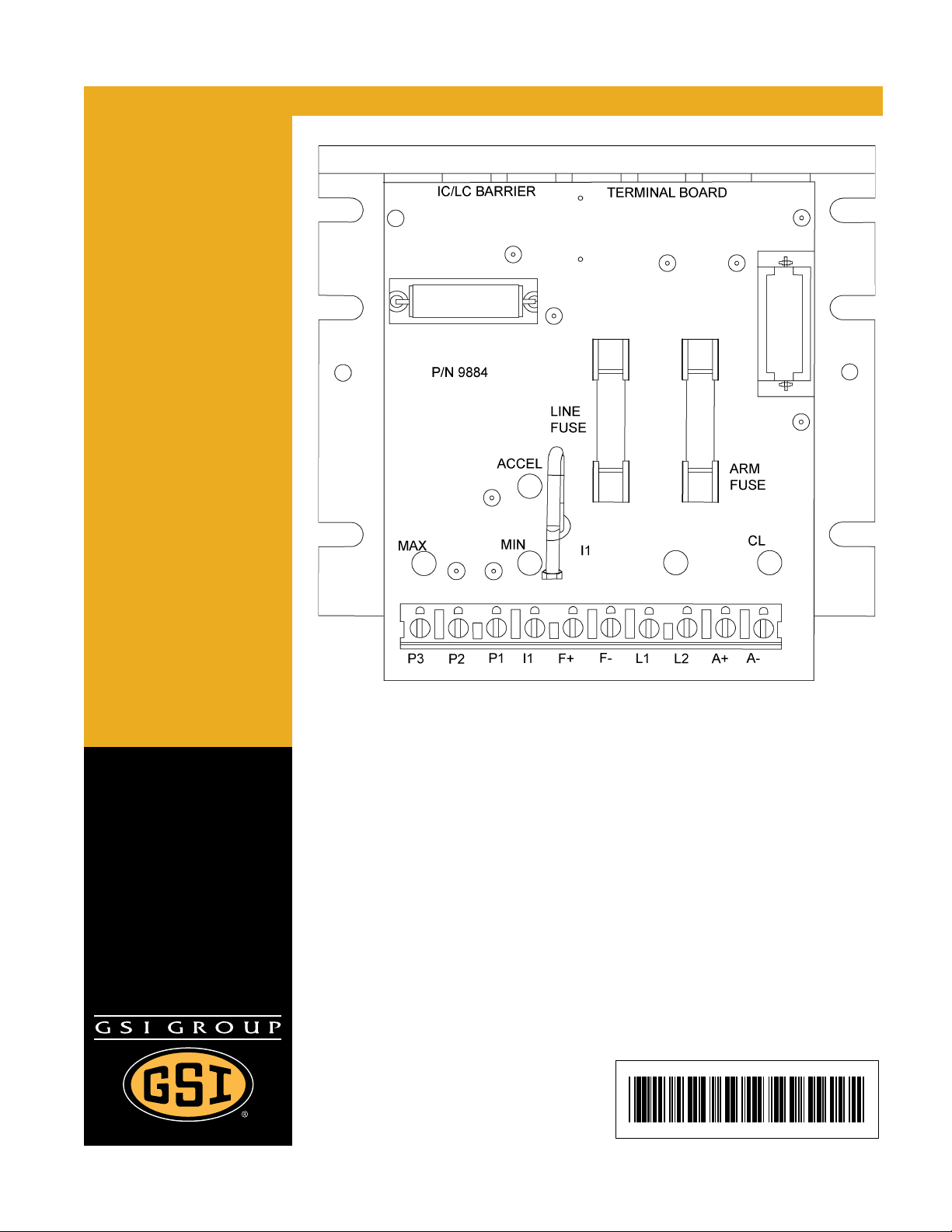
Resistor
P3 P2 P1 L1 L2 A+ A-
SCR Board Terminal Locations
Terminals L1 and L2 are the input terminals. When the unload system is turned ON, there should be
220 VAC across these terminals. (See Figure 3C.)
Terminals A+ and A- are the output terminals. The voltage across these terminals is DC and will vary
depending on the setting on the speed control dial.
NOTE: For this calibration procedure, disregard the minimum and maximum potentiometers on the
SCR Board.
IMPORTANT: If installing a new SCR Board, be sure to remove the resistor (shown in Figure 3C below)
from the old board and install it in the new board. To do this, pull the resistor out from the
2 pin socket of the old board and install in the same socket on the new board. Pictured
below are horsepower resistors. The original components that came with the dryer
should remain.
Figure 3C SCR Board Terminals
PNEG-1544 Vision SCR Board Calibration 9
Page 10
3. SCR Drive Setup
Manual Setup Instructions
IMPORTANT:
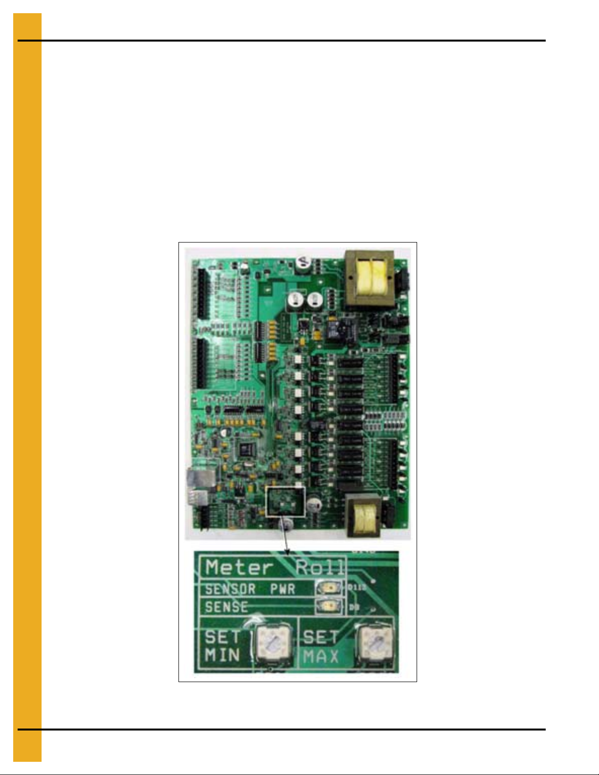
1. Locate the Main I/O Board in the upper control box. For a reference, See Figure 3A on Page 7.
Near the bottom of the Main I/O board are two (2) potentiometers labeled SET MINIMUM and
SET MAXIMUM. (See Figure 3D.) Turn both of these potentiometers as far to the right (clockwise)
as they will go.
NOTE: Be careful not to turn the potentiometers too far or with too much force. They only turn
All of the speed controls on the SCR Drive are now set in the Vision Software using the touch
screen on the dryer control panel. Do not try to setup the SCR drive using the minimum and
maximum potentiometers on the SCR Board. Make sure the CL potentiometer is set at the
4 o’clock position and the IR potentiometer is set to the 10 o’clock position.
approximately one revolution and too much force or attempting to turn them too far could
result in broken parts.
Figure 3D Main I/O Board with a Close Up View of the
Set Minimum and Set Maximum Potentiometers
10 PNEG-1544 Vision SCR Board Calibration
Page 11

3. SCR Drive Setup
2. Go to the “Default Operation Screen” on the Vision touch control and select the button.
(See Figure 3E.)
Figure 3E
3. When the “Select Hardware Setup Parameter To Modify” screen ap pears (which will be referred to as
the “Setup Screen” for the remainder of this manual), press the button.
(See Figure 3F.)
Figure 3F
PNEG-1544 Vision SCR Board Calibration 11
Page 12

3. SCR Drive Setup
Extended
setup button
4. On the “Unload Parameters” screen, set the maximum unloading rate to 100% and the minimum
unloading rate to 0% by using the “INCREASE” and “DECREASE” buttons. Touch the “ACCEPT”
button to store these values. (See Figure 3G.)
Figure 3G
NOTE: These settings must be changed in order to properly calibrate the SCR drive. The settings
can be returned to another desired setting after the calibration process is complete.
5. Return to the “Default Operation Screen”. Turn the Unload switch to “Manual” and set the meter roll
speed setpoint to 5% (50).
6. Press the “Setup” button at the bottom of the “Default Operation Screen” to return to the “Setup
Screen”. Touch the “Extended Setup” button. (See Figure 3H.)
Figure 3H
12 PNEG-1544 Vision SCR Board Calibration
Page 13

3. SCR Drive Setup
Setup metering
rolls
Up and down buttons
Accept button
7. Press the “Diagnostics” button to display the “Systems Diagnostics” screen, then press the “Setup
Metering Rolls” button. (See Figure 3I.)
Figure 3I
8. Use a voltmeter to read DC voltage. Place the red lead on the A+ terminal of the SCR Board and
the black lead on the A- terminal. (See Figure 3C on Page 9 for the location of these terminals
and Figure 3A on Page 7 for the location of the SCR Board. Touch the Minimum Speed “Up” and
“Down” buttons and watch the display on the voltmeter. The voltage reading on the voltmeter should
be as close to 9 VDC as possible. Once the voltmeter displays this, touch the “ACCEPT” button.
(See Figure 3J.)
PNEG-1544 Vision SCR Board Calibration 13
Figure 3J
Page 14

3. SCR Drive Setup
9. After pressing the “ACCEPT” button, return to the “Default Operation Screen”.
10. Press the Meter Roll Adjustment knob to change the meter roll setpoint to 100% (1000) and then
touch “ACCEPT/EXIT” and return to the “Meter Roll Output Voltage Setup” screen.
11. Place the voltmeter leads on the A+ and A- terminals of the SCR Board as described previously and
touch the Maximum Speed “Up” and “Down” buttons to get a DC voltage reading of 180 VDC on
the voltmeter. Once the voltmeter reads as close to 180 VDC across both terminals, touch the
“ACCEPT” button.
12. Re-check both the minimum and maximum voltage to ensure both settings were accepted
as desired.
NOTE: Remember to go to the “Moisture Control Setup” screen and put the Minimum Speed setting back
to at least 5% and the Maximum Speed setting to a speed best suited for the unload equipment.
14 PNEG-1544 Vision SCR Board Calibration
Page 15

4. Warranty
9101239_1_CR_rev7.DOC (revised July 2009)
GSI Group, LLC Limited Warranty
The GSI Group, LLC (“GSI”) warrants products which it manufactures to be free of defects in materials and workmanship
under normal usage and conditions for a period of 12 months after sale to the original end-user or if a foreign sale,
14 months from arrival at port of discharge, whichever is earlier. The end-user’s sole remedy (and GSI’s only obligation)
is to repair or replace, at GSI’s option and expense, products that in GSI’s judgment, contain a material defect in materials
or workmanship. Expenses incurred by or on behalf of the end-user without prior written authorization from the GSI
Warranty Group shall be the sole responsibility of the end-user.
Warranty Extensions:
The Limited Warranty period is extended for the following products:
Product Warranty Period
Performer Series Direct Drive Fan Motor 3 Years
AP Fans and Flooring
Cumberland
Feeding/Watering
Systems
Grain Systems Grain Bin Structural Design 5 Years
Grain Systems
Farm Fans
Zimmerman
All Fiberglass Housings Lifetime
All Fiberglass Propellers Lifetime
Feeder System Pan Assemblies 5 Years **
Feed Tubes (1-3/4" and 2.00") 10 Years *
Centerless Augers 10 Years *
Watering Nipples 10 Years *
Portable and Tower Dryers 2 Years
Portable and Tower Dryer Frames and
Internal Infrastructure †
5 Years
* Warranty prorated from list price:
0 to 3 years - no cost to end-user
3 to 5 years - end-user pays 25%
5 to 7 years - end-user pays 50%
7 to 10 years - end-user pays 75%
** Warranty prorated from list price:
0 to 3 years - no cost to end-user
3 to 5 years - end-user pays 50%
† Motors, burner components
and moving parts not included.
Portable dryer screens included.
Tower dryer screens not included.
GSI further warrants that the portable and tower dryer frame and basket, excluding all auger and auger drive components,
shall be free from defects in materials for a period of time beginning on the twelfth (12
and continuing until the sixtieth (60
th
) month from the date of purchase (extended warranty period). During the extended
th
) month from the date of purchase
warranty period, GSI will replace the frame or basket components that prove to be defective under normal conditions
of use without charge, excluding the labor, transportation, and/or shipping costs incurred in the performance of this
extended warranty.
Conditions and Limitations:
THERE ARE NO WARRANTIES THAT EXTEND BEYOND THE LIMITED WARRANTY DESCRIPTION SET FORTH
ABOVE. SPECIFICALLY, GSI MAKES NO FURTHER WARRANTY OF ANY KIND, EXPRESS OR IMPLIED,
INCLUDING, WITHOUT LIMITATION, WARRANTIES OF MERCHANTABILITY OR FITNESS FOR A PARTICULAR
PURPOSE OR USE IN CONNECTION WITH: (I) PRODUCT MANUFACTURED OR SOLD BY GSI OR (II) ANY ADVICE,
INSTRUCTION, RECOMMENDATION OR SUGGESTION PROVIDED BY AN AGENT, REPRESENTA TIVE OR
EMPLOYEE OF GSI REGARDING OR RELATED TO THE CONFIGURATION, INSTALLATION, LAYOUT, SUITABILITY
FOR A PARTICULAR PURPOSE, OR DESIGN OF SUCH PRODUCTS.
GSI shall not be liable for any direct, indirect, incidental or consequential damages, including, without limitation, loss of
anticipated profits or benefits. The sole and exclusive remedy is set forth in the Limited Warranty, which shall not exceed
the amount paid for the product purchased. This warranty is not transferable and applies only to the original end-user. GSI
shall have no obligation or responsibility for any representations or warranties made by or on behalf of any dealer, agent
or distributor.
GSI assumes no responsibility for claims resulting from construction defects or unauthorized modifications to products
which it manufactured. Modifications to products not specifically delineated in the manual accompanying the equipment at
initial sale will void the Limited Warranty.
This Limited Warranty shall not extend to products or parts which have been damaged by negligent use, misuse, alteration,
accident or which have been improperly/inadequately maintained. This Limited Warranty extends solely to products
manufactured by GSI.
Prior to installation, the end-user has the responsibility to comply with federal, state and local codes which apply to the
location and installation of products manufactured or sold by GSI.
PNEG-1544 Vision SCR Board Calibration 15
Page 16

This equipment shall be installed in accordance with
the current installation codes and applicable
regulations which should be carefully followed in all
cases. Authorities having jurisdiction should be
consulted before installations are made.
Copyright © 2010 by GSI Group
Printed in the USA
GSI Group
1004 E. Illinois St.
Assumption, IL 62510-0020
Phone: 1-217-226-4421
Fax: 1-217-226-4420
www.gsiag.com
 Loading...