

Page 1
Instructions
1004 East Illinois Street • Assumption, IL 62510 • 1-217-226-4421
Wiring Diagrams
Electronic HH-1089 Time Delay Reset Wiring Instructions
Use this page to install the HH-1089E as a replacement to the HH-1089 time delay reset switch in early
model heaters. Refer to Figure 1 on Page 2 of the electronic time delay to identify the connection
terminals. Connect the wires according to the symbols used on Figure 1 on Page 2 with the symbols in
the wiring schematics for the heaters.
Installation
1. Remove old time delay reset from the control box.
2. Install new time delay into existing hole in heater control box and secure with the nut provided.
3. Connect wire lead from the solenoid circuit to terminal #1 on the time delay. (Symbol A)
4. Connect wire lead from the flame probe to terminal #3 on the time delay. (Symbol B)
5. Connect wire lead from the housing High-Limit to terminal #4 on the time delay. (Symbol C)
6. Connect one end of the supplied wire for the neutral circuit (white with black stripe) to the “N” terminal
of the time delay. (Symbol D)
7. Connect the other end of the supplied wire for the neutral circuit to terminal #2 in the heater
control. (Symbol D)
Refer to the operating section on Page 5 of this instruction sheet for reference to the time delay operation.
Date: 10-12-09 PNEG-1530
Printed in the U.S.A.
Copyright © 2009 by GSI Group
www.gsiag.com
PNEG-1530
Page 1 of 5
Page 2
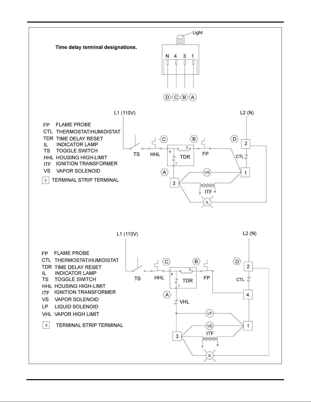
Wiring Diagrams
Figure 1
Page 2 of 5 PNEG-1530
Page 3

Wiring Diagrams
Electronic HH-1089 Time Delay Reset Wiring Instructions for
Heaters with HF-7356 Terminal Strip
Use Figure 2 on Page 4 to install the HH-1089E as a replacement to the HH-1089 time delay reset switch
on heaters that have the flame checking terminal strip.
Installation
Chitown and Standard Controls with Metal Control Box
1. Remove old time delay reset from the control box.
2. Install new time delay into existing hole in heater control box and secure with the nut provided.
3. Connect the PURPLE wire from terminal #2 on the heater terminal strip to terminal #4 on the
time delay.
4. Connect the YELLOW wire from terminal #3 on the heater terminal strip to terminal #3 on the
time delay.
5. Connect the ORANGE wire from terminal #4 on the heater terminal strip to terminal #1 on the
time delay.
6. Connect one end of the supplied wire for the neutral circuit (white with black stripe) to the
“N” terminal of the time delay.
7. Connect the other end of the supplied wire for the neutral circuit to terminal #5 on the heater
terminal strip.
Standard Heaters with Plastic Control Box
Follow the steps above and these additional instructions for heaters with plastic control boxes.
8. Remove the lights and control power switch from the control box front panel.
9. Remove existing control box decal (DC-1696) and clean the surface of the control box where the
decal was removed.
10. Install the new control decal (DC-1878) onto the control box. Use the holes and box edges as a
guide for decal alignment.
11. Drill a 3/8" diameter hole for the reset at the location indicated on the Figure 2 on Page 4.
12. Install new time delay in this hole and secure with the nut provided.
13. Re-install the lights and power switch to the appropriate holes labeled on the decal.
PNEG-1530 Page 3 of 5
Page 4

Wiring Diagrams
Figure 2
Page 4 of 5 PNEG-1530
Page 5

Wiring Diagrams
HH-1089E Time Delay Reset Operation
The electronic time delay will indicate the operating condition of the heater through the LED light shown
on Figure 3. This light should be on the exterior control panel of the heater when the unit is installed
correctly. This light is very helpful in identifying the status of the flame probe (open or closed) and will
indicate a lock out condition.
Start-up
The light should be ON when the ON/OFF switch is set to ON. This indicates that the heater has power
and the flame probe is closed. The gas solenoid should open and ignitor should spark. The light will
remain on until the flame probe opens. The light should go OFF if flame is established within the
30 second trial for ignition.
If flame is not present or the probe does not open, the light will blink continuously after the 30 second
time period. It will blink continuously until the heater is reset.
Turn power OFF for 10 second to reset a lock out condition. The light will stop blinking after the
10 second time period. The heater cannot be restarted if the light is blinking continuously.
Thermostat Cycle
The heater thermostat will cycle the gas solenoid OFF when temperature is reached. The flame probe
should cool to a closed condition when this occurs. The thermostat will also cool to a closed condition
with a drop in plenum temperature. The thermostat closure is a call for heat and the normal start-up for
the time delay begins again.
A condition can occur where the thermostat can call for heat before the flame probe cools to a closed
condition. The light on the time delay will flash once at thermostat closure and remain off until the flame
probe closes again. The heater will not operate until this “closed” condition of both switches is achieved.
Figure 3 Flame Probe Light on Time Delay
Light Status Indication
ON
OFF
BLINKING
Flame probe is closed.
Time delay in 30 second trial for ignition period.
Normal operation with flame present.
Flame probe open. Thermostat closed.
Normal operation with no flame present.
Flame probe open. Thermostat open.
Lock out: Flame probe closed after 30 second.
To reset: Turn power OFF. Wait 10 second. Turn power ON.
PNEG-1530 Page 5 of 5
 Loading...