

Page 1
PNEG-1510
Top Dry 24', 30' and 36'
Manual Batch
Construction and Owner ’s Manual
PNEG-1510
Date: 02-18-13
Page 2

2 PNEG-1510 Top Dry 24', 30' and 36' Manual Batch
Page 3

Table of Contents
Contents
Chapter 1 Safety ..................................................................................................................................................... 5
Safety Guidelines .................................................................................................................................. 5
Chapter 2 Decals .................................................................................................................................................... 6
Roof Damage Warning and Disclaimer ................................................................................................. 6
Chapter 3 Foundation Requirements ................................................................................................................... 9
Foundation Requirements for Top Dry Bins (4.00" Top Dry Bin Corrugation) ...................................... 9
Circular Foundation Form ............................................................................................................. ... ... 10
Octagonal Foundation Form ............................... ... ... .... ... ... ... .... ... ... ... ... .......................................... ... 11
Inline Centrifugal Fan Pad ................................................................................................................... 12
Duct and Drying Fan Pad Optional ..................................................................................................... 13
Frost Free Foundation Top Dry Bins ............................. ... ... ... .... ... ... ... ... .... ... ... ... .... ... ......................... 14
Frost Free Pad .......... ....................................... ... ... ... .... ... ... ... ....................................... ............. ... ... ... 15
Anchor Bolt Placement ........................................................................................................................ 16
Chapter 4 Hardware ............................................................................................................................................. 17
Hardware/Bolting Requirements ......................................................................................................... 17
Location of Accessories ...................................................................................................................... 20
Very Important ..................................................................................................................................... 21
Chapter 5 Sidewall Construction ........................................................................................................................ 22
Sidewall Gauges ....... ....................................... ... ... ... .... ... ... ... ....................................... ... .......... ... ... ... 22
Sidewall Erection Instructions ... ... .......................................... .... ......................................... ....... ... ... ... 23
Caulking Detail .................................................................................................................................... 24
Sidewall Construction Instructions ............................................................. ... ...................................... 25
Lifting Jacks and Brackets .................................................................................................................. 26
Lifting Jack Usage ............................... ... ... ... .... ... ... ... .... ... ... ... ....................................... ............. ... ... ... 27
Chapter 6 Stiffener Details .................................................................................................................................. 28
Stiffener Gauges ....... ....................................... ... ... ... .... ... ... ... ....................................... .......... ... ... ... ... 28
Outside Stiffeners ................................................................................................................................ 29
Top Stiffener Starting Location ......................................................................................................... ... 31
Stiffener Installation and Location ....................................................................................................... 32
Bolting Requirements Two (2) Stiffeners per Sidewall Sheet ............................................................. 33
Stiffener and Seam Locations ............................................................................................................. 34
Chapter 7 “C” Channels ...................................................................................................................................... 35
Stiffener to “C” Channel Bracket Installation....................................................................................... 35
“C” Channel Installation ................ .... ... ... ....................................... ... ... ... .... ... ... ... ................................ 36
Center Collar Assembly ...................................................................................................................... 37
Chapter 8 Installation .......................................................................................................................................... 38
Rafter Installation and Floor Support Angle Attachment ..................................................................... 38
Purlin Installation ................................................................................................................................. 39
Dump Hopper Installation ....................... ... ... .... ... ... ... .... ... ... ... .... ......................................... .......... ...... 42
Floor Sheet Installation ....................................................................................................................... 42
24' Leveling Band Post Installation ..................................................................................................... 43
30' Leveling Band Post Installation ..................................................................................................... 44
36' Leveling Band Post Installation ..................................................................................................... 45
Flashing Bolt Installation ..................................................................................................................... 46
Eave Flashing Installation ................................................................................................................... 46
Eave Flashing Splice ........................................................................................................................... 47
Outer Dump Chutes ............................................................................................................................ 48
Intermediate Dump Chutes ................................................................................................................. 49
24' Leveling Band Location ................................................................................................................. 50
30' Leveling Band Location ................................................................................................................. 51
36' Leveling Band Location ................................................................................................................. 53
PNEG-1510 Top Dry 24', 30' and 36' Manual Batch 3
Page 4

Table of Contents
Chapter 9 Assembly ............................................................................................................................................ 55
Center Cone Assembly ....................................................................................................................... 55
Center Cone Installation ...................................................................................................................... 55
Roof Assembly .................................................................................................................................... 56
Pulley Assembly ................... ... ... ... .... ...................................... .... ... ... ... ... .... ........................................ 57
Dump Chute Chain Assembly ............................................................................................................. 58
Winch Assembly .................................................................................................................................. 60
Fan Entrance Sheets .......................................................................................................................... 61
Top Dry Access Door Assembly (TD-100996) .................................................................................... 62
Detailed Layout for Proper Location of Platforms ............................................................................... 63
Access Door Platform (TDP-5012) ...................................................................................................... 64
Large Platform Assembly for 42" Fan ................................................................................................. 65
42" Fan Diffuser Instructions and Installation ...................................................................................... 68
Cross Over Platform Assembly (for use with stairs) (TDP-5013) ........................................................ 70
Perforated Center Band ...................................................................................................................... 71
Optional Rotary Switch Roof Locations ............................................................................................... 72
Optional Rotary Switch Panel Locations ............................................................................................. 72
Optional Installation of Roof Mounted Level Switches ........................................................................ 73
Optional Installation of Wall Mounted Rotary Switches ............................... ............................. ........... 74
Transition Installation (TR-4734) ......................................................................................................... 75
Transition Assembly (TR-4734) .......................................................................................................... 76
Chapter 10 Accessories ...................................................................................................................................... 77
2 Ring Door Installation Instructions .................................................................................................. 77
2 Ring Door Assembly ....................................................................................................................... 78
Optional Bin Step Assembly (WD-042) ............................................................................................. 80
Base Angle ........................................................................................................................................ 81
Base Stiffener Shim ........................................................................................................................... 81
Chapter 11 Warranty ............................................................................................................................................ 83
4 PNEG-1510 Top Dry 24', 30' and 36' Manual Batch
Page 5
1. Safety
DANGER
WARNING
CAUTION
NOTICE
This is the safety alert symbol. It is used to alert you
to potential personal injury hazards. Obey all safety
messages that follow this symbol to avoid possible
injury or death.
WARNING indicates a hazardous situation which, if not
avoided, could result in death or serious injury.
CAUTION, used with the safety alert symbol, indicates a
hazardous situation which, if not avoided, could result in
minor or moderate injury.
NOTICE is used to address practices not related to
personal injury.
DANGER indicates a hazardous situation which, if not
avoided, will result in death or serious injury.
Safety Guidelines
This manual contains information that is important for you, the owner/operator, to know and understand.
This information relates to protecting personal safety and preventing equipment problems. It is the
responsibility of the owner/operator to inform anyone operating or working in the area of this equipment
of these safety guidelines. To help you recognize this information, we use the symbols that are defined
below. Please read the manual and pay attention to these sections. Failure to read this manual and its
safety instructions is a misuse of the equipment and may lead to serious injury or death.
PNEG-1510 Top Dry 24', 30' and 36' Manual Batch 5
Page 6
2. Decals
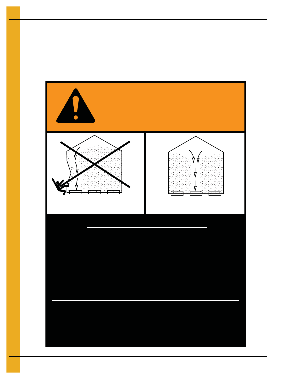
The manufacturer does not warrant any roof damage caused by excess ive v acuum or internal
pressure from fans or other air moving systems. Adequate ventilation and/or “makeup air”
devices should be provided for all powered air handling systems. The manufacturer does not
recommend the use of downward flow systems (suction). Severe roof damage can result from
any blockage of air passages. Running fans durin g high humidity/cold weather conditions can
cause air exhaust or intake ports to freeze.
Roof Damage Warning and Disclaimer
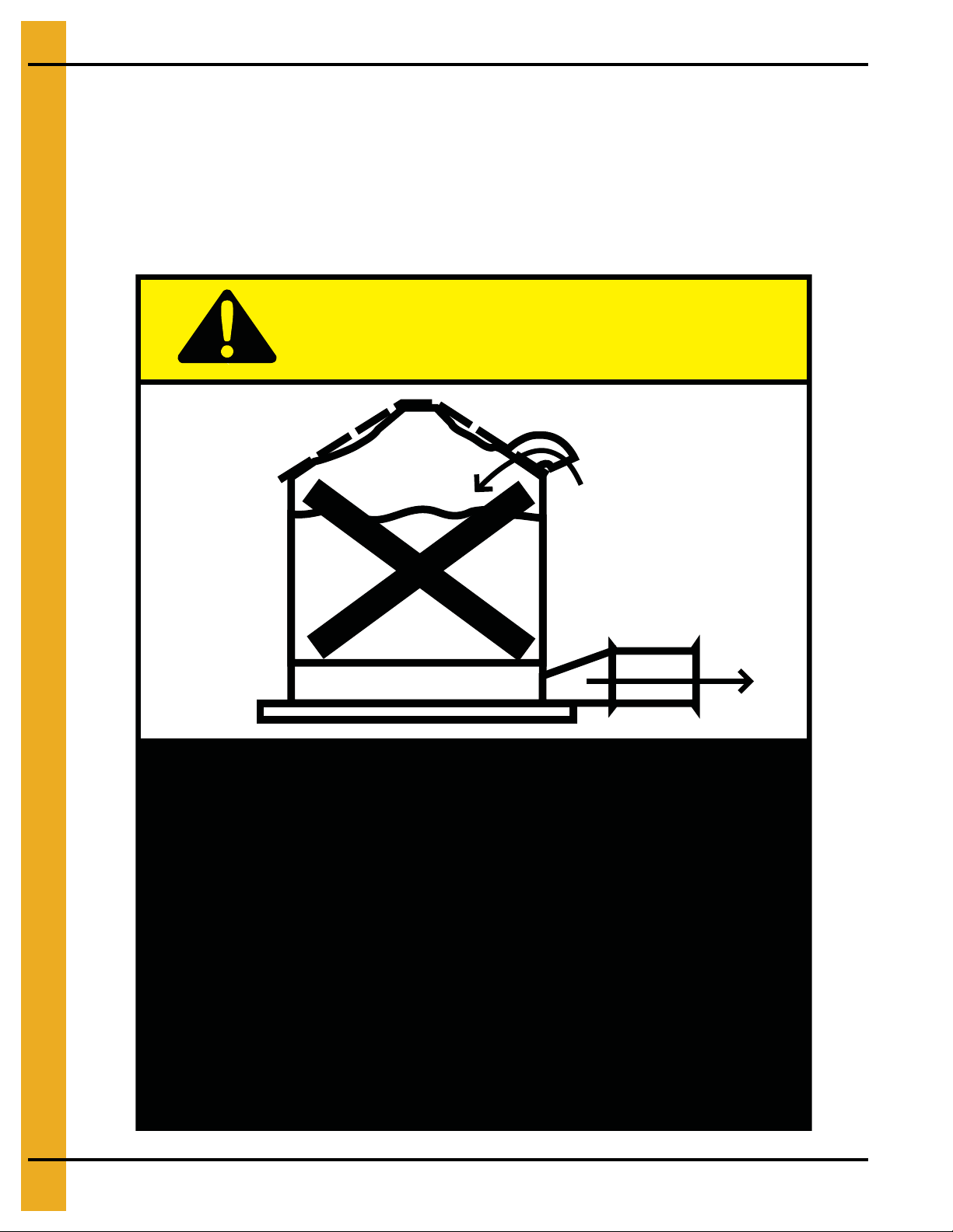
CAUTION!
Excessive vacuum (or pressure) may
damage roof. Use positive aeration
system. Make sure all roof vents are
open and unobstructed. Start roof
fans when supply fans are started.
Do not operate when conditions exist
that may cause roof vent icing.
DC-969
6 PNEG-1510 Top Dry 24', 30' and 36' Manual Batch
Page 7
2. Decals
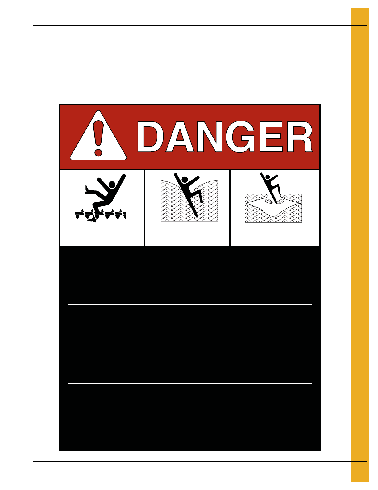
Rotating flighting will
kill or dismember.
Flowing material will
trap and suffocate.
Crusted material will
collapse and suffocate.
Keep clear of all augers.
DO NOT ENTER this bin!
Failure to heed these
warnings will result in
serious injury or death.
If you must enter the bin:
1. Shut off and lock out all power.
2. Use a safety harness and safety line.
3. Station another person outside the bin.
4. Avoid the center of the bin.
5. Wear proper breathing equipment or respirator.
DC-GBC-1A
ATTENTION: The decal shown below should be present on the outside of the door cover of the 2 ring,
24" porthole door cover and the roof manway cover. If a decal has been damaged or is missing in any of
these locations, contact the manufacturer for a free replacement decal.
GSI Decals
1004 E. Illinois St.
Assumption, IL. 62510
Phone: 1-217-226-4421
PNEG-1510 Top Dry 24', 30' and 36' Manual Batch 7
Page 8
2. Decals
Failure to heed these warnings
could result in serious injury, death,
structural damage or collapse of tank.
1. Use CENTER FLOOR OUTLET ONLY until NO grain
remains above this outlet.
2. Side floor outlets to be used ONLY when above
condition is satisfied.
3. Lock all side floor outlets to avoid accidental
premature use.
4. See manufacturers instructions for proper use of
factory supplied sidedraw (wall) discharge systems.
UNLOADING INSTRUCTIONS:
DC-GBC-2A
WARNING
DON’T
DO
ATTENTION: The decal shown below should be present on the outside of the door cover of the 2 ring,
24" porthole door cover and the roof manway cover. If a decal has been damaged or is missing in any of
these locations, contact the manufacturer for a free replacement decal.
GSI Decals
1004 E. Illinois St.
Assumption, IL. 62510
Phone: 1-217-226-4421
8 PNEG-1510 Top Dry 24', 30' and 36' Manual Batch
Page 9

3. Foundation Requirements
Foundation Requirements for Top Dry Bins (4.00" Top Dry
Bin Corrugation)
Requirements
The following foundation recommendations are a revision to earlier manuals distributed by the
GSI Group.
NOTE: There are changes in founda tion dimensions from past publications. These dimensions are critical
to the proper installation and function of each foundation.
Selecting the Proper Site
The selected site should be level, firm and free from underlying debris. The bin can be installed
satisfactorily on slopes, but as the slope increases, additional labor and materials are required for the
foundation. The concrete foundation surface must be level. If some fill is required, it should be watered
and tamped thoroughly to prevent uneven settling from the weight of th e bin. Naturally, the site must allow
convenient access for easy loading and unloading, plus provide additional space for future units. Also
consider the positioning of handling equipment, availability of electricity and the placement of fans, heaters
and gas tanks.
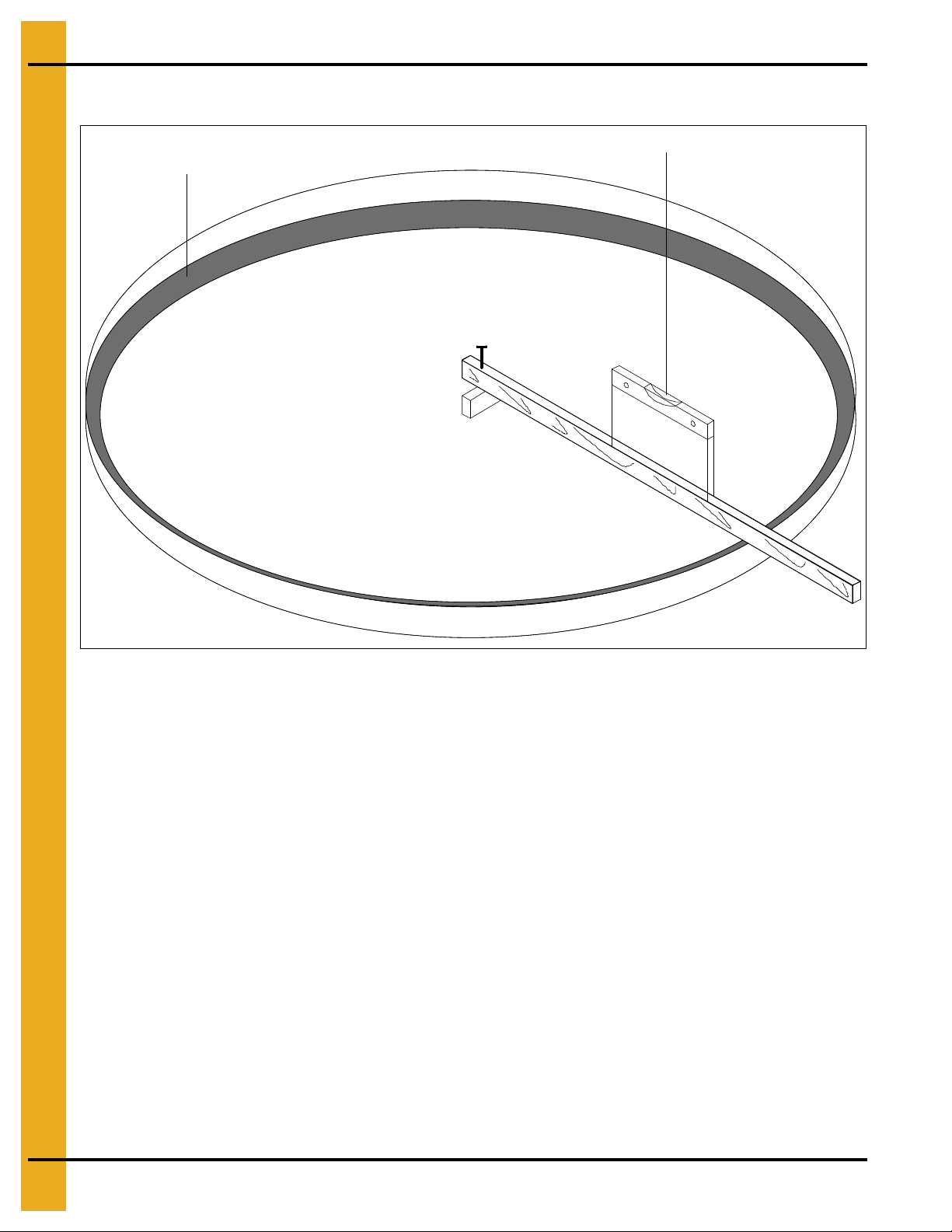
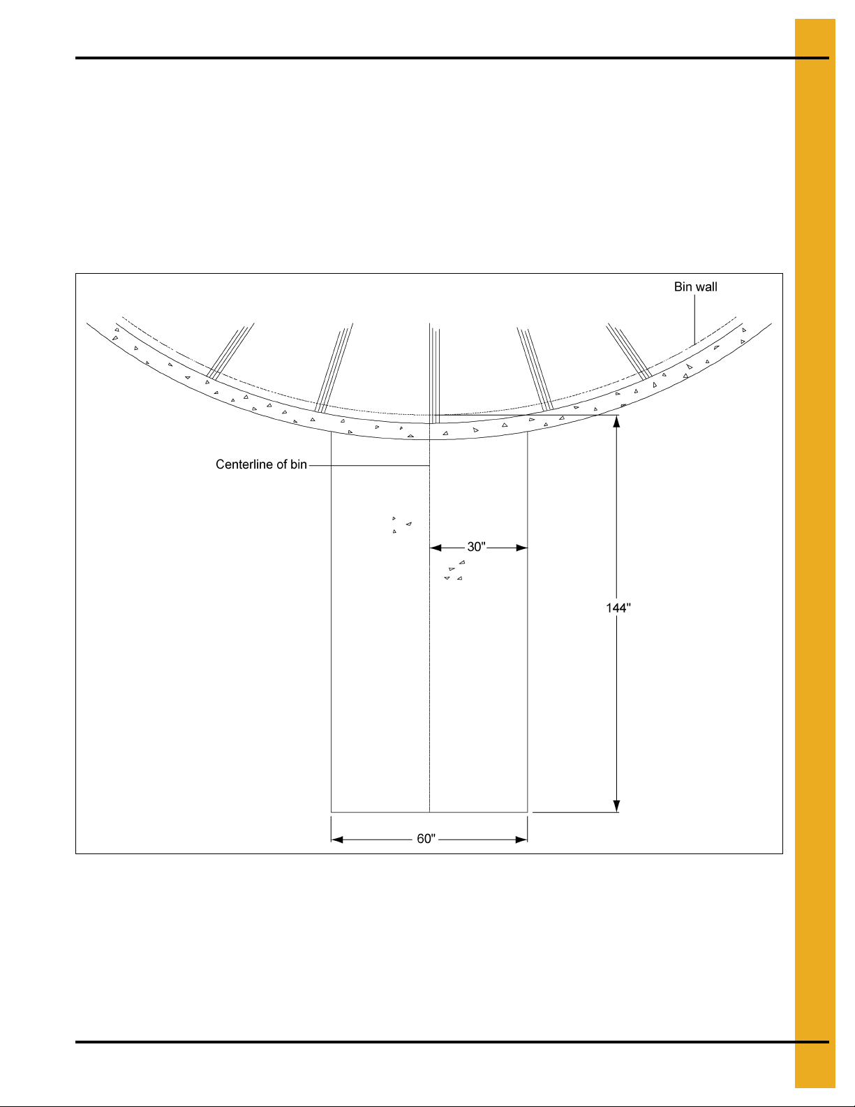
Scribe the Diameter
Having determined the center of the site, drive a small 2 x 4 in the ground to mark the center point of the
foundation. The top of the stake should be the same height as the finished foundation will be. Using one
large spike, nail a straight 2 x 4 (approximately 2' longer than the radius of the bin) to the top of the center
spike. The swiveling 2 x 4 will act as a compass, enabling you to scribe the correct diameter of the
foundation and later locate the anchor and stiffener bolt locations. (NOTE: Making the 2 x 4 2' longer than
the radius allow the 2 x 4 to also be used as a leveling device and for pulling concrete.) (See Figure 3A.)
Figure 3A
PNEG-1510 Top Dry 24', 30' and 36' Manual Batch 9
Page 10
3. Foundation Requirements
Circular Foundation Form
Footing trench
Carpenter’s level
Figure 3B
Prepare the Foundation
Having scribed the diameter of the foundation, proceed by digging the footing of the foundation. This
consists of a large circular trench dug just inside the foundation line. (Refer to foundation details for
necessary information.) Once the footing has been dug, you are ready to build the forms. It is important
that the form be rigid enough to hold its shape against the poured concrete. Also, the foundation must be
flat. Sloped floors cannot be used in drying bins. A carpenter’s level placed on t op of the 2 x 4 will enable
you to set the top of the forms to match the top of the center stake. Check the form work with a transit to
ensure a uniform elevation for the entire foundation. (See Figure 3B.)
10 PNEG-1510 Top Dry 24', 30' and 36' Manual Batch
Page 11
3. Foundation Requirements
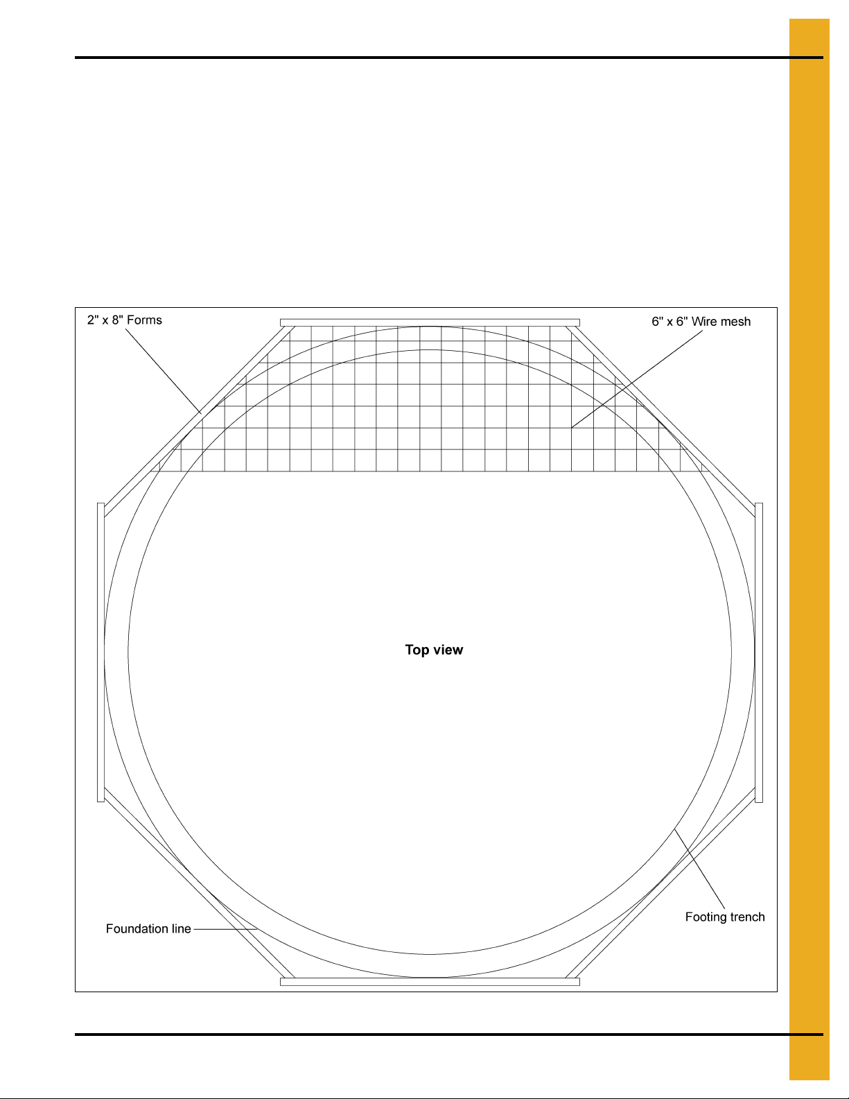
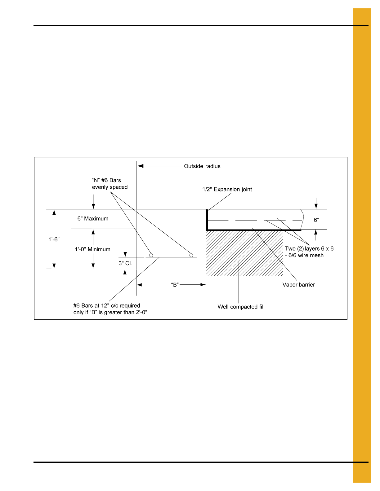
Octagonal Foundation Form
There are two (2) styles of foundation forms commonly used. The first is the circular form depicted in
Figure 3B on Page 10. The second style can be made of 2" x 8" boards set into a square with corners
blocked off to form an octagon. (See Figure 3C.) This eight (8) sided form will approximate a circle and
can be constructed quite easily.
When the foundation form is completed install reinforcement rods by either welding or wiring in place.
Place 2" of compacted sand on the inside level of the foundation. The sand is then covered with a 4 mil
plastic moisture barrier. 6" x 6" Wire mesh (two (2) mats), covering the entire area of the foundation,
completes the preparation of the bin’s foundation. You are now ready to begin pouring concrete.
NOTE: All concrete is to have a minimum compressive strength of 3000 PSI at 28 days.
Figure 3C
PNEG-1510 Top Dry 24', 30' and 36' Manual Batch 11
Page 12
3. Foundation Requirements
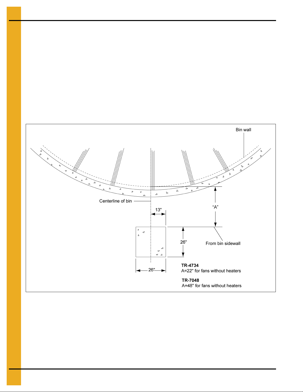
Inline Centrifugal Fan Pad
Placement of the Fan Pad: GSI Transitions/Fans only.
If a fan is to be installed, refer to Figure 3D to determine the concrete pad size.
1. The top of this pad should be level with the top of the bin’s foundation.
2. Recommended pad thickness is 4" minimum.
3. Front of pad should be perpendicular to bin wall.
4. Pad for heater not required.
IMPORTANT: Fan pad and fan must be leveled an d smooth for proper operation. Vibration problems can
result from improper fan leveling.
Figure 3D
12 PNEG-1510 Top Dry 24', 30' and 36' Manual Batch
Page 13
3. Foundation Requirements
Duct and Drying Fan Pad Optional
Placement of the Duct Fan Pad: GSI Top Dry Duct System only.
Refer to Figure 3E to determine the duct pad size.
1. The top of this pad should be level with the top of the bin’s foundation.
2. Recommended pad thickness is 4" minimum.
3. Front of pad should be perpendicular to bin wall.
Figure 3E
PNEG-1510 Top Dry 24', 30' and 36' Manual Batch 13
Page 14

3. Foundation Requirements
Frost Free Foundation Top Dry Bins
Diameter of Bin: 24'
Corrugation : 4.00"
Ring # B N
6 1'-1" 2 12'-9" 900 600 200 13
7, 8 1'-9" 2 12'-9" 900 600 200 15
9, 10 2'-6" 3 13'-2" 900 600 400 18
Diameter of Bin: 30'
Corrugation : 4.00"
Ring # B N
6 1'-2" 2 15'-9" 1400 900 200 19
7, 8 1'-10" 2 15'-10" 1400 900 200 21
9, 10 2'-8" 3 16'-1" 1400 900 500 25
11 3'-8" 4 16'-5" 1400 900 700 29
Outside
Radius
Outside
Radius
Sq. Ft. Mesh
6 x 6 - 6/6
Sq. Ft. Mesh
6 x 6 - 6/6
Optional #4
18" x 18" Grid (Ft.)
Optional #4
18" x 18" Grid (Ft.)
Length #6
Bar (Ft.)
Length #6
Bar (Ft.)
To tal Cu. Yds.
Concrete
Total Cu. Yds.
Concrete
Diameter of Bin: 36'
Corrugation : 4.00"
Ring # B N
6 1'-3" 2 18'-9" 2000 1300 300 26
7, 8 2'-0" 2 18'-11" 2000 1300 400 30
9, 10 2'-10" 3 19'-0" 2000 1300 600 33
11, 12 3'-11" 4 19'-6" 2000 1300 900 39
Outside
Radius
Sq. Ft. Mesh
6 x 6 - 6/6
Optional #4
18" x 18" Grid (Ft.)
Length #6
Bar (Ft.)
Total Cu. Yds.
Concrete
14 PNEG-1510 Top Dry 24', 30' and 36' Manual Batch
Page 15
3. Foundation Requirements
Frost Free Pad
NOTES:
1. Foundation site should be well drained and free of vegetation or debris.
2
2. Foundation design is based on a minimum soil bearing capacity of 3000 lbs/ft
capacity is in doubt, contact a local soil testing engineer.
3. Concrete shall have a minimum compressive strength of 3000 PSI at 28 days.
4. Requirements for reinforcement do not include overlap.
5. Lap all circumferential bars 35 bar diameters and stagger all laps in plan 3'-0".
6. All material used for backfill inside the ring wall should be a clean, well graded, crushed stone or
sand-gravel mixture. Backfill should be placed in 6" lifts and well compacted.
. If soil bearing
Figure 3F
PNEG-1510 Top Dry 24', 30' and 36' Manual Batch 15
Page 16
3. Foundation Requirements
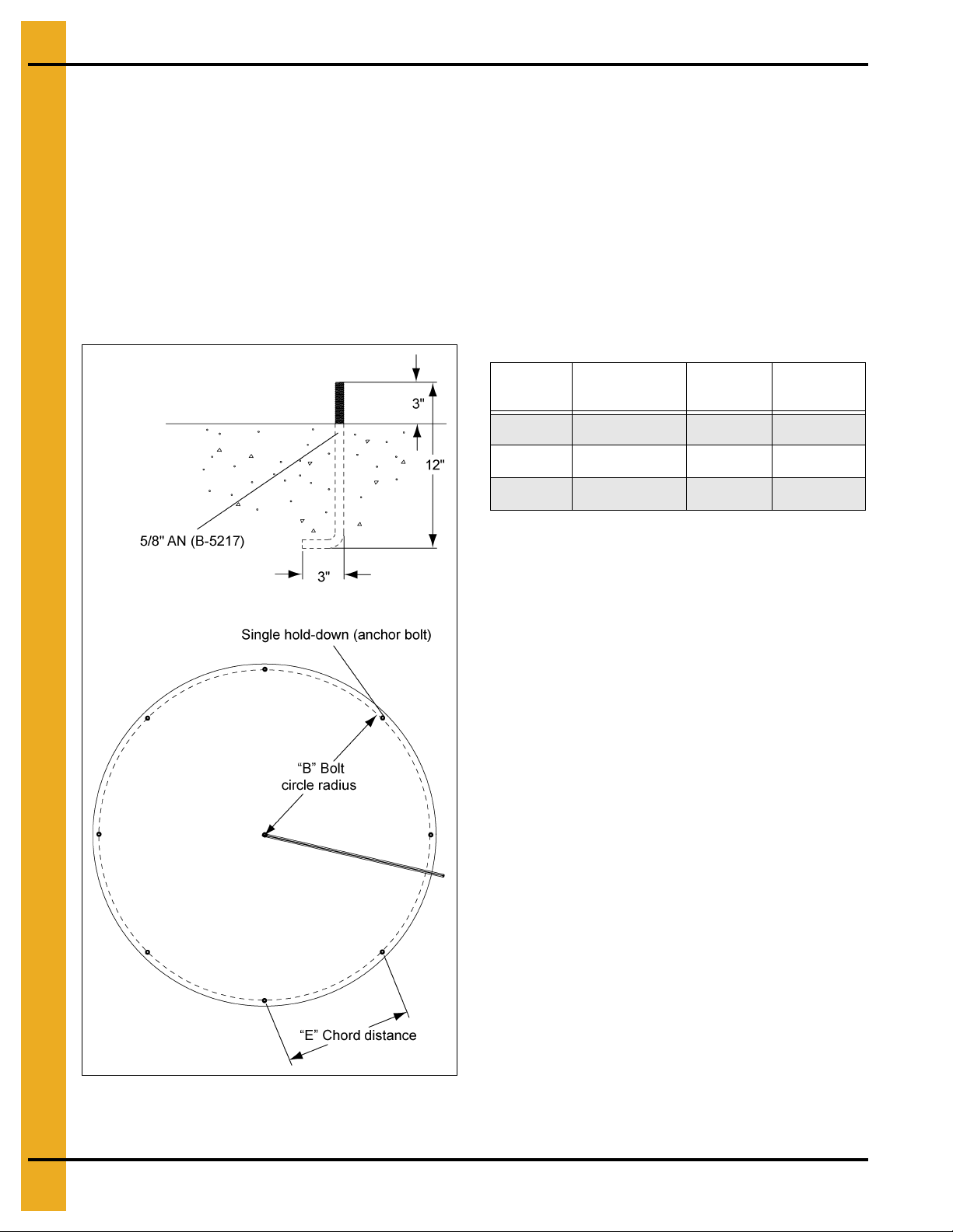
Anchor Bolt Placement
Having poured and leveled the concrete, use the center stake and straight 2" x 4" again to find the bolt
circle radius for the outside hold-down brackets. Select a starting point and stretch a pre-measured chord
along the imaginary circle formed by the bolt circle radius. Take into consideration the placement o f these
bolts so as not to interfere with the positions of bin doors and transitions. (Refer to below Chart for
necessary radius and chord lengths.) Take the time and work carefully since accuracy is important.
Work both directions from first anchor bolt location, this will help eliminate possible error in laying out
anchor bolts. On larger bins sight across starting anchor bolt and center pin and place anchor bolt on
opposite side of anchor bolt radius. From this point you can work both directions from both anchor bolts.
NOTE: Top edge of slab where the bin wall sets must be held to within 1/8" of level.
Bin
Diameter
24' 12' - 2-7/8" 16 4' - 9-5/16"
30' 15' - 2-11/16" 20 4' - 9-1/8"
36' 18' - 2-1/2" 24 4' - 9-1/16"
“B” Bolt
Circle Radius
# of
Anchors
“E” Chord
Distance
Figure 3G Anchor Bolt
16 PNEG-1510 Top Dry 24', 30' and 36' Manual Batch
Page 17
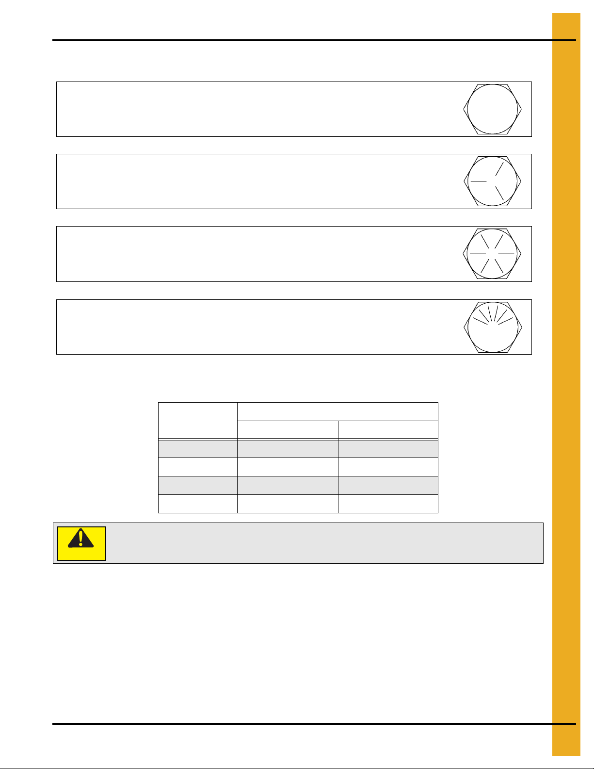
Hardware/Bolting Requirements
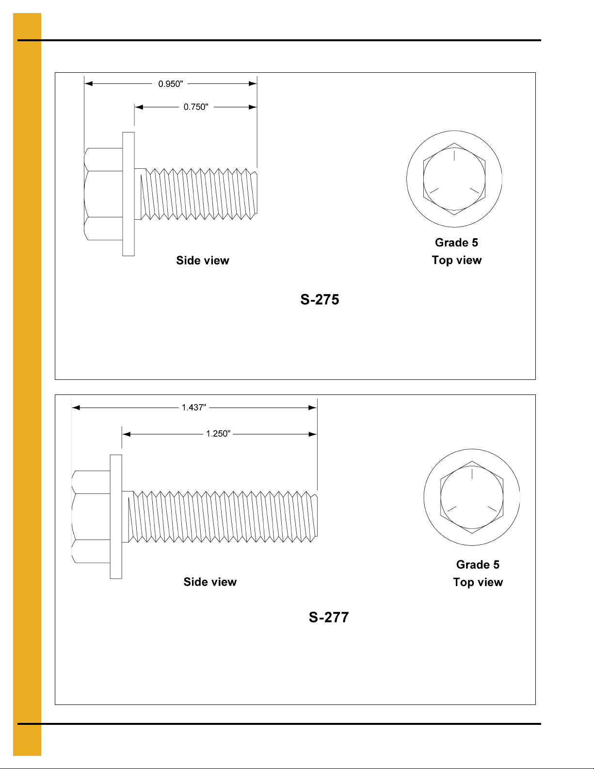
NOTE: Grade 2 bolts are designated with a plain head.
NOTE: Grade 5 bolts are designated by three (3) slash marks on the head.
All 5/16" diameter bolts are to be grade 5 or higher.
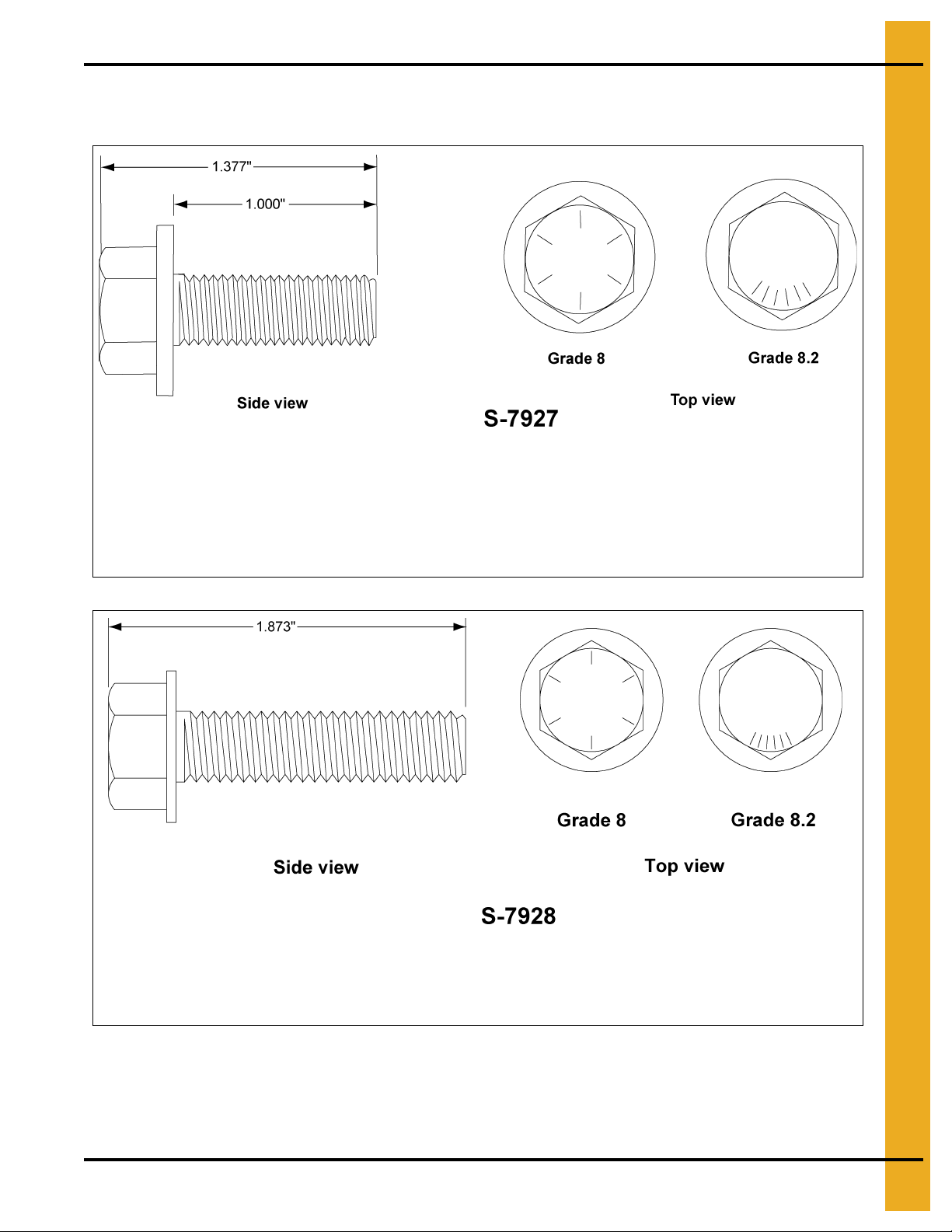
NOTE: Grade 8 bolts are designated by six (6) slash marks on the head.
NOTE: Grade 8.2 bolts are designated by six (6) slash marks on the head in a
sunrise pattern.
All 3/8" diameter bolts are to be grade 8 or 8.2.
Under no condition shall any other bolts be substituted for those supplied by
GSI Group.
4. Hardware
IMPORTANT: Do not tighten bolts to exceed the torque specifications listed below.
Torque (Ft. lbs.)
CAUTION
IMPORTANT:
Bolt Size
Minimum Maximum
5/16"-18 15 20
3/8"-16 35 42
7/16"-14 65 72
1/2"-13 95 105
Hardware Usage - 20 Gauge - 15 gauge sidewall sheets, use 5/16" x 3/4" bolts and
nuts (S-275).
14 Gauge and 13 gauge sidewall sheets, use 5/16" x 3/4" bolts and
nuts (S-275).
Use 5/16" x 1-1/4" (S-277) for attaching floor flashing to the sidewall.
PNEG-1510 Top Dry 24', 30' and 36' Manual Batch 17
Page 18
4. Hardware
0.3125" x 0.750" Pre-assembled with a steel backed neoprene washer.
This bolt is used to connect horizontal and vertical seams for 13 gauge and thinner sidewall sheets
to each other and to bolt the stiffeners to the sidewall sheets. It is also used in attaching roof panels
to the top sidewall sheet and attaching roof panels and flashing to the center collar.
0.3125" x 1.250" Pre-assembled with a steel backed neoprene washer.
This bolt is primarily used to connect roof panels together where they overlap. It is also used at the
bottom of the flat bottomed bins to attach the base angle to the sidewall sheet. A small number of
these are provided for joints and FC-42076 splice plates for the stiffeners to sidewall connection.
Refer to Top Dry Tank Bolting Requirements for Complete Bolt Usage
18 PNEG-1510 Top Dry 24', 30' and 36' Manual Batch
Page 19
Refer to Top Dry Tank Bolting Requirements for Complete Bolt
0.375" x 1.000" Hex flanged head without a plastic sealing washer.
This bolt is used to splice the stiffeners together on the flanges. A steel flat washer is used on the
nut side of the connection. They are also used on “C” channel splices and mounting “C” channel to
wall bracket.
0.375" x 1.500" Hex flanged head without a plastic sealing washer.
This bolt is used to attach the wall bracket to the sidewall and stiffener. A steel flat washer is used
on the nut side of the connection.
Usage (Continued)
4. Hardware
NOTE: The only washers shipped loose with the bins are the steel flat washers. The 5/16" steel flat washer
(S-845) is used where the base angle attaches to the sheet and some are used at the main e ave
clips. The 3/8" steel flat washers (S-248) are used at the stiffener splices and some are used in
PNEG-1510 Top Dry 24', 30' and 36' Manual Batch 19
the roof rafter splices.
Page 20
4. Hardware
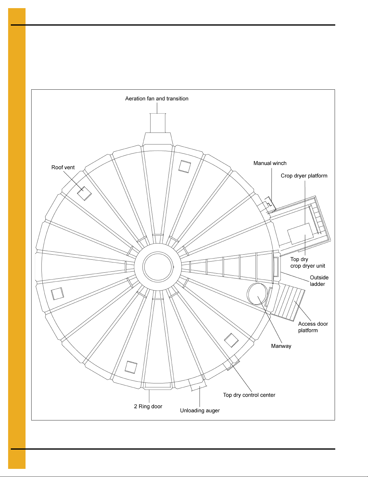
Location of Accessories
Below is a typical Top Dry bin layout showing suggested locations of Top Dry accessories. When locating
the manway be sure the outside ladder will not interfere with other accessories below. Roof vents sh ould
be spaced evenly around the roof. (Quantity will vary with individual systems.) (See Figure 4A.)
NOTE: The Top Dry system should be provided with a dependable equipment ground.
Figure 4A
20 PNEG-1510 Top Dry 24', 30' and 36' Manual Batch
Page 21
Very Important
4. Hardware
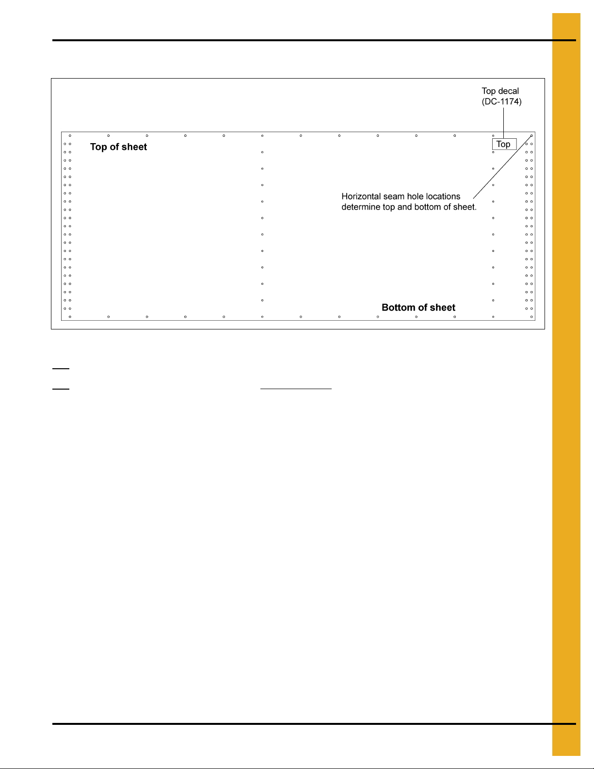
Figure 4B Sheet Shown as Viewed from the Inside of Bin
All 4.00" corrugated sidewall sheets must be placed correctly.
4.00" corrugated sidewall sheets have a top and bottom.
All
Failure to observe this will not allow the door to fit properly.
Carefully review the erection manual and place sidewall sheets as shown in Figure 4B.
PNEG-1510 Top Dry 24', 30' and 36' Manual Batch 21
Page 22

5. Sidewall Construction
Sidewall Gauges
Tank
Diameter
(Ft.)
24 5 20 Ga. 20 Ga. 20 Ga. 20 Ga. 20 Ga.
24 6 20 Ga. 20 Ga. 20 Ga. 20 Ga. 20 Ga. 20 Ga.
24 7 18 Ga. 20 Ga. 20 Ga. 20 Ga. 20 Ga. 20 Ga. 20 Ga.
24 8 18 Ga. 18 Ga. 20 Ga. 20 Ga. 20 Ga. 20 Ga. 20 Ga. 20 Ga.
24 9 17 Ga. 18 Ga. 18 Ga. 20 Ga. 20 Ga. 20 Ga. 20 Ga. 20 Ga. 20 Ga.
24 10 17 Ga. 17 Ga. 18 Ga. 18 Ga. 18 Ga. 20 Ga. 20 Ga. 20 Ga. 20 Ga. 20 Ga.
30 5 18 Ga. 18 Ga. 18 Ga. 18 Ga. 20 Ga.
30 6 18 Ga. 18 Ga. 18 Ga. 18 Ga. 18 Ga. 20 Ga.
30 7 17 Ga. 18 Ga. 18 Ga. 18 Ga. 18 Ga. 18 Ga. 20 Ga.
30 8 17 Ga. 17 Ga. 18 Ga. 18 Ga. 18 Ga. 18 Ga. 18 Ga. 20 Ga.
30 9 17 Ga. 17 Ga. 17 Ga. 18 Ga. 18 Ga. 18 Ga. 18 Ga. 18 Ga. 20 Ga.
30 10 16 Ga. 17 Ga. 17 Ga. 17 Ga. 18 Ga. 18 Ga. 18 Ga. 18 Ga. 18 Ga. 20 Ga.
30 11 16 Ga. 17 Ga. 17 Ga. 17 Ga. 17 Ga. 18 Ga. 18 Ga. 18 Ga. 18 Ga. 18 Ga. 20 Ga.
36 5 17 Ga. 18 Ga. 18 Ga. 18 Ga. 20 Ga.
# of Rings
of Sidewall
Sidewall
Base Ring
Sidewall
Ring #2
Sidewall
Ring #3
Sidewall
Ring #4
Sidewall
Ring #5
Sidewall
Ring #6
Sidewall
Ring #7
Sidewall
Ring #8
Sidewall
Ring #9
Sidewall
Ring #10
Sidewall
Ring #11
36 6 17 Ga. 18 Ga. 18 Ga. 18 Ga. 18 Ga. 20 Ga.
36 7 16 Ga. 17 Ga. 18 Ga. 18 Ga. 18 Ga. 18 Ga. 20 Ga.
36 8 16 Ga. 16 Ga. 17 Ga. 18 Ga. 18 Ga. 18 Ga. 18 Ga. 20 Ga.
36 9 16 Ga. 16 Ga. 16 Ga. 17 Ga. 18 Ga. 18 Ga. 18 Ga. 18 Ga. 20 Ga.
36 10 15 Ga. 16 Ga. 16 Ga. 16 Ga. 17 Ga. 18 Ga. 18 Ga. 18 Ga. 18 Ga. 20 Ga.
36 11 14 Ga. 15 Ga. 15 Ga. 16 Ga. 16 Ga. 17 Ga. 18 Ga. 18 Ga. 18 Ga. 18 Ga. 20 Ga.
NOTE: Fan entrance sheets and plenum access door sheets are located in the second ring fr om the top
of the bin, just below the upper drying floor.
22 PNEG-1510 Top Dry 24', 30' and 36' Manual Batch
Page 23
5. Sidewall Construction
Sidewall Erection Instructions
Before bolting the sidewall sheets together, check that you have the proper gauge steel for the first ring.
The higher gauge numbers denote the thinner materials. (For example, 22 gauge material is thinner than
14 gauge.) In erecting most grain bins the thinnest material usually goes on top, therefore the first sid ewall
ring you assemble will be the top ring of the bin. Check the various gauges of the bin with the color code
chart and begin building accordingly. REMEMBER...... Assemble the top ring first.
Color Code Chart
Gauge Color Code Gauge Color Code
22 White 14 Green
20 Red
19 Black/Yellow 12 Black
18 Orange
17 Pink/Light Blue 10 Light Blue
16 Blue
15 Brown/Red 8 Yellow
13 Yellow/Blue
11 Pink
9 Blue/Orange
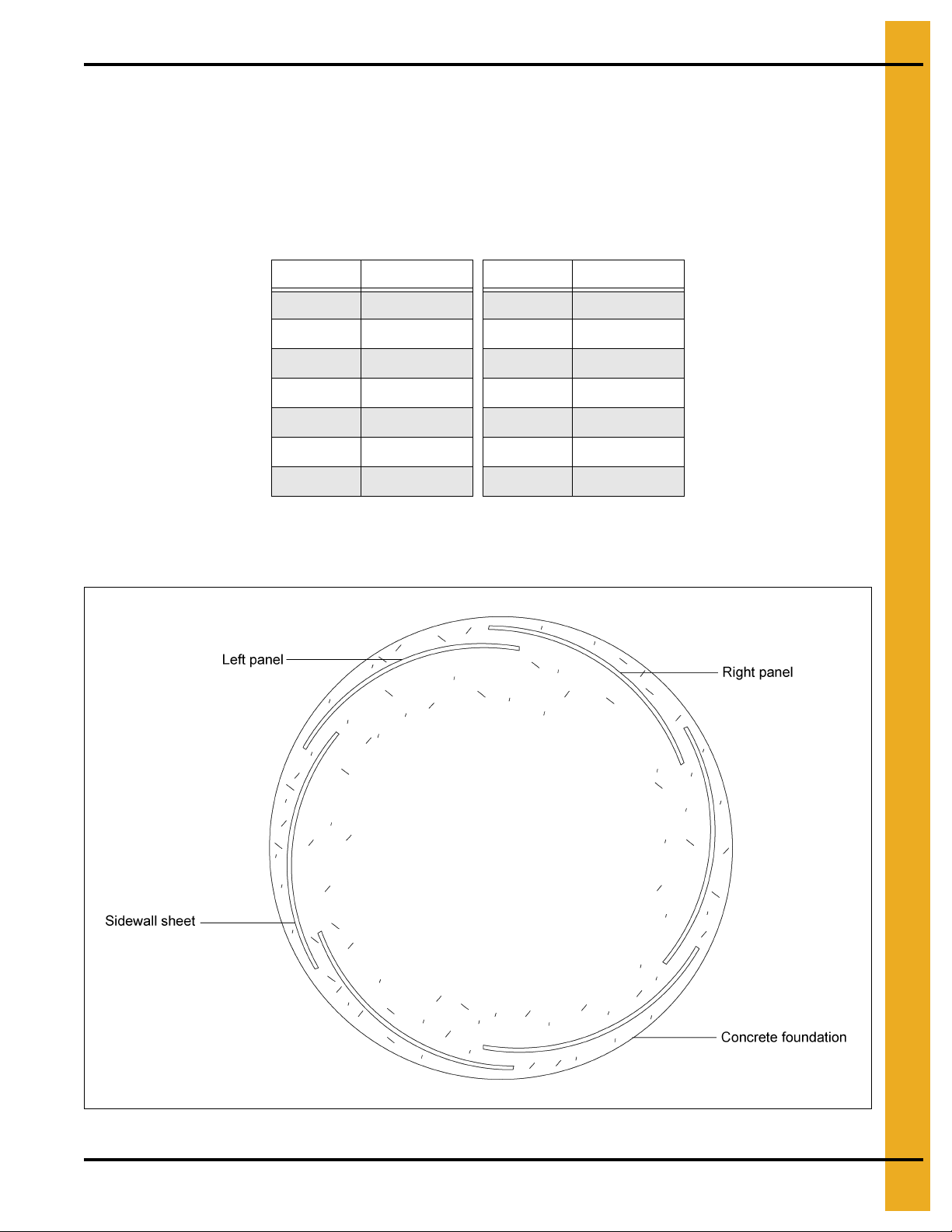
Once you have selected the proper gauge material, begin assembling all sidewall sheets in the following
manner: Standing on the inside the bin, place the left panel to the inside with the right panel to the outside.
(See Figure 5A.) Check to see that the sidewall shee t is “Right side up”. Refer to Page 26 for details.
Figure 5A
PNEG-1510 Top Dry 24', 30' and 36' Manual Batch 23
Page 24
5. Sidewall Construction
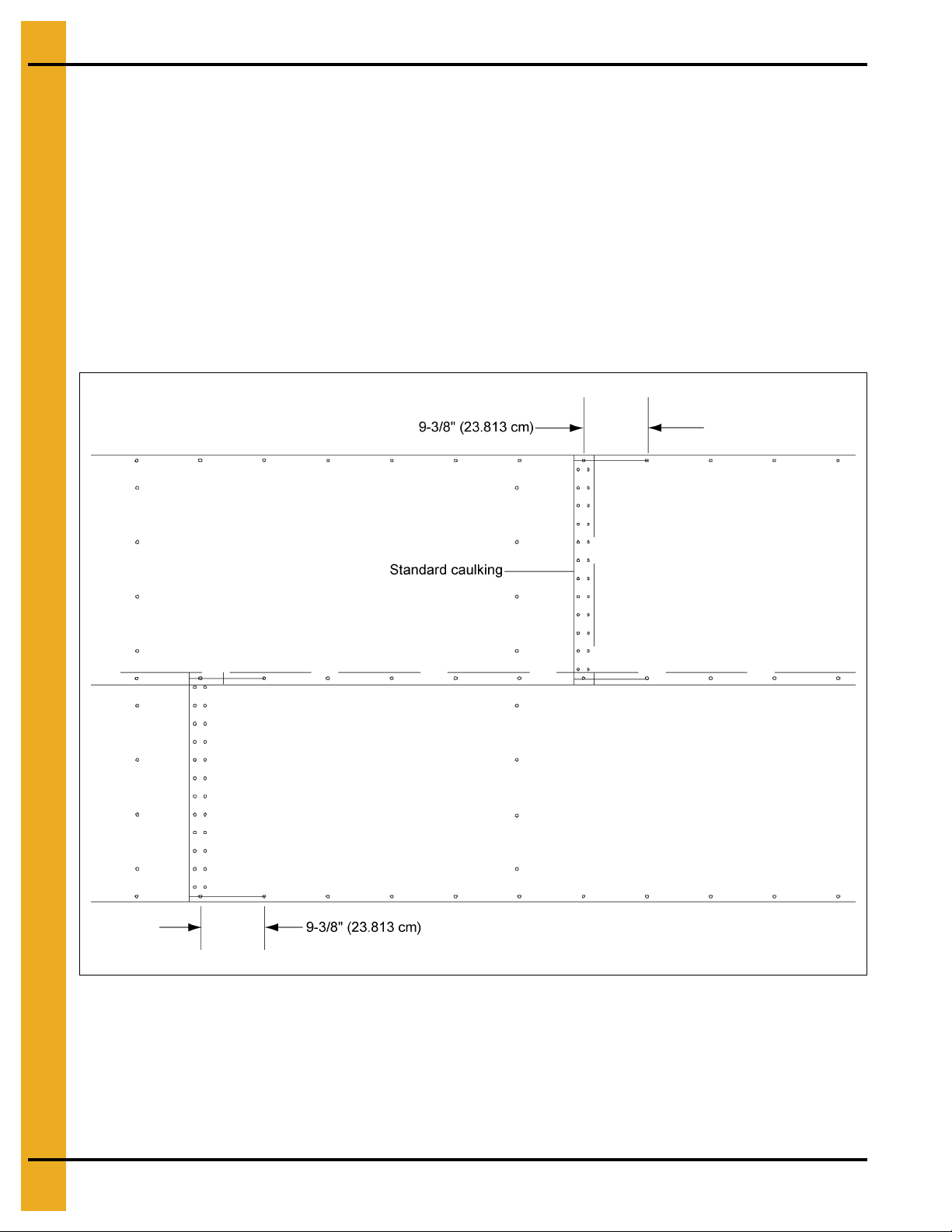
Caulking Detail
NOTE: The rope caulking is installed before each sheet is assembled. Apply rope caulking between the
last vertical row of bolts and edge of outside sheet. There is sufficient caulking for all vertical seams
on storage and drying bins. Wipe sheet clean where caulking is to be applied.
Using correct size bin bolts throughout, begin assembling sidewall sheets end to end (overlapping the
same way throughout) until the ring is completed. All body sheet bolts are to be installed with the bolt head
and its neoprene washer to the outside and the nut on the inside. Do not tighten bolts until all sheets are
assembled and form a complete ring. Attach lifting brackets to stiffener bolt holes. These straps, coupled
to the jacks will enable you to later elevate the bin. Now, tighten the bolts in sequence, starting from the
center and working to the edge in both directions. This permits the sidewall sheets to draw-up evenly.
Complete 1 ring and stop. You are now ready to assemble the roof. Refer to roof erection manual for
roof assembly instructions located in roof hardware box. (See Figure 5B.)
Figure 5B Standard Sidewall Sheet as Viewed from Inside
24 PNEG-1510 Top Dry 24', 30' and 36' Manual Batch
Page 25
5. Sidewall Construction
Sidewall Construction Instructions
Figure 5C
Using correct size bin bolts throughout, begin assembling sidewall sheets end to end (overlapping the
same way throughout) until the ring is complete. All body sheet bolts are to be installed with the bolt head
and its neoprene washer to the outside and the nut on the inside. Do n ot tighten bolts u ntil all sh eets are
assembled and form a complete ring. Tighten the bolts in sequence, starting from the center and work to
the edge in both directions. This permits the sidewall sheets to draw-up evenly.
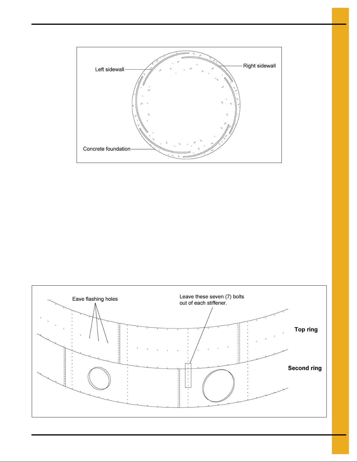
After assembling the second ring, lift the top ring sheets in place, add top stiffeners, build the Top Dry
floor, then the roof.
NOTE: The sidewall sheets used for the top ring are punched to accommodate the eave flashing bolts.
NOTE: The fan entrance sheet and access door are located in the second ring. Attach the top stiffe ners,
leaving out the seven (7) bolts indicated in Figure 5D at each stiffener location. Install the flashing
bolts from the outside.
Figure 5D Top 2 Rings
PNEG-1510 Top Dry 24', 30' and 36' Manual Batch 25
Page 26
5. Sidewall Construction
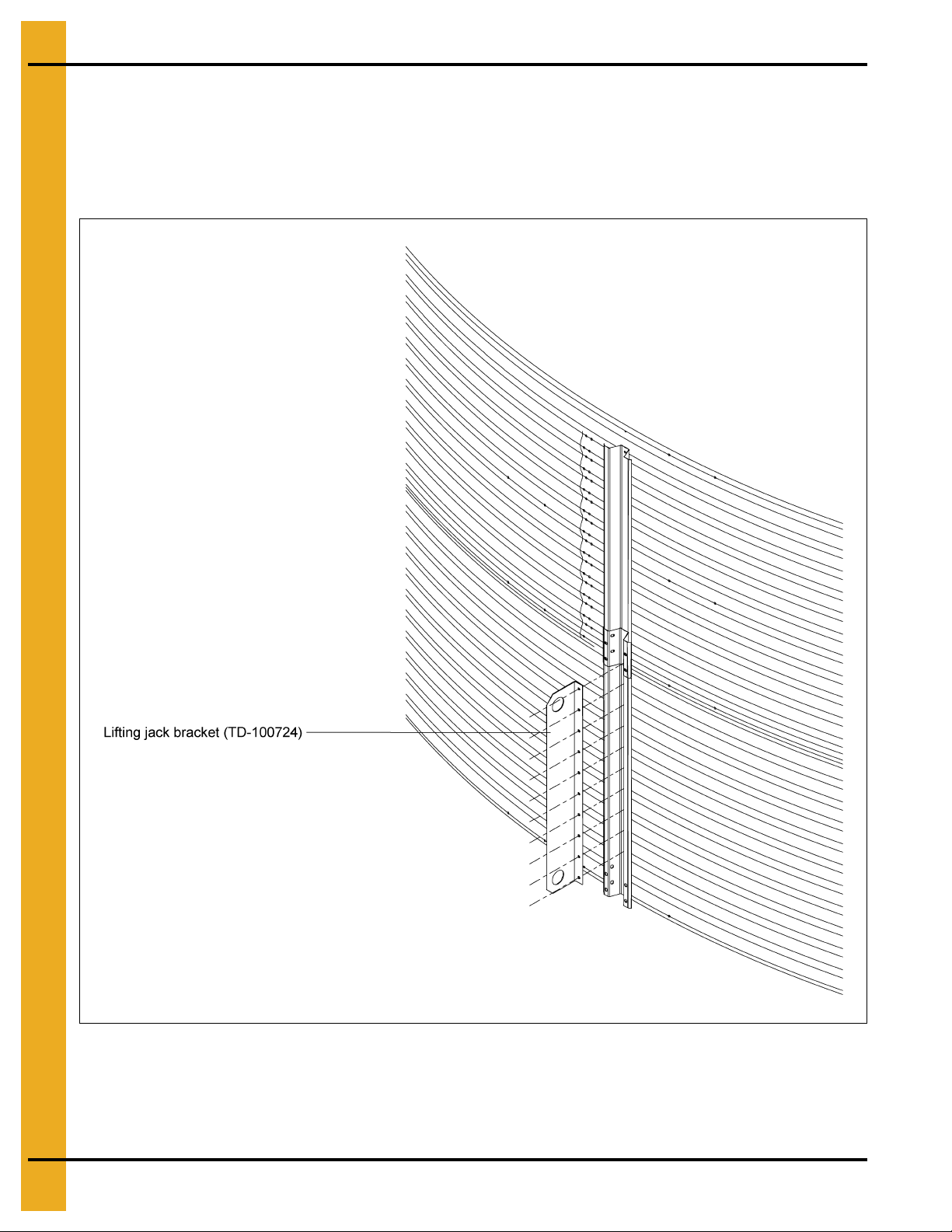
Lifting Jacks and Brackets
NOTE: The number of lifting jacks required is best determined by personal experience. Factors such as
bin size, soil compaction, wind velocity, jack design, etc., are all to be considered when deciding
how many to use. If in doubt, use one jack on every other stiffener. GSI recommends heavy duty
jacks rated at 6000 lbs. or more. (See Figure 5E.)
Figure 5E
26 PNEG-1510 Top Dry 24', 30' and 36' Manual Batch
Page 27

5. Sidewall Construction
The number of lifting jacks required is best determined by personal experience.
Factors such as bin size, soil compaction, wind velocity, jack design, etc., are all
to be considered when deciding how many to use. If in doubt, use one jack on
every vertical seam. Be sure to use heavy duty jacks for commercial installation.
Lifting Jack Usage
Give some thought before starting the bin on location of door and other accessories. Proper placement of
lifting jacks in relationship to anchor bolts could make a difference on odd or even ring bins. Walk-through
door is centered between two (2) stiffener anchor bolts. The sidewall shee ts are also staggered 1/2" fr om
end to end.
WARNING
Figure 5F
Lifting brackets should be attached to the stiffeners. Normally you will need to attach to at least four (4)
bolts per stiffener. Anchor all jacks securely with metal stakes and cable. Now raise the bin just high
enough to assemble the next ring. When lifting the bin, crank all jacks at an equal rate. This will prevent
bowing previously assembled rings and make for easier hole alignment. To the inside
the next ring. Be sure to stagger the sheets and select the proper gauge material. Lower the bin on the
foundation after assembling and tightening bolts on the new ring or rings. When installing duct work for
the drying fans be sure to install it as you go up with the bin letting the duct set on the foundation before
the bolts are tightened to assure proper alignment. Now re-bolt the lifting stra ps to the lowest ring in place
thus far. Continue ring additions until you are ready for door installation. You may want to leave sheets
loose to make the attachment of the stiffeners easier.
NOTE: Add inside and outside ladders to bin walls as you continue to raise the bin.
PNEG-1510 Top Dry 24', 30' and 36' Manual Batch 27
of the first ring, bolt
Page 28

6. Stiffener Details
Stiffener Gauges
Nominal
Dia. of
Sidewall
(Ft.)
Rings of
Sidewall
24 5 14 Ga. 16 Ga. 16 Ga. 16 Ga.
24 6 12 Ga. 14 Ga. 16 Ga. 16 Ga.
24 7 12 Ga. 14 Ga. 16 Ga. 16 Ga. 16 Ga.
24 8 12 Ga. 12 Ga. 14 Ga. 16 Ga. 16 Ga.
24 9 10 Ga. 12 Ga. 12 Ga. 14 Ga. 14 Ga. 16 Ga.
24 10 8 Ga. 10 Ga. 12 Ga. 14 Ga. 16 Ga. 16 Ga.
30 5 12 Ga. 14 Ga. 16 Ga. 16 Ga.
30 6 12 Ga. 14 Ga. 16 Ga. 16 Ga.
30 7 12 Ga. 12 Ga. 14 Ga. 16 Ga. 16 Ga.
30 8 10 Ga. 12 Ga. 14 Ga. 16 Ga. 16 Ga.
30 9 10 Ga. 12 Ga. 12 Ga. 14 Ga. 16 Ga. 16 Ga.
30 10 8 Ga. 10 Ga. 12 Ga. 14 Ga. 16 Ga. 16 Ga.
30 11 8 Ga. 10 Ga. 12 Ga. 12 Ga. 14 Ga. 16 Ga. 16 Ga.
# of
Stiffener
Base
Ring
Stiffener
Ring #2
Stiffener
Ring #3
Stiffener
Ring #4
Stiffener
Ring #5
Stiffener
Ring #6
Stiffener
Ring #7
Stiffener
Ring #8
Stiffener
Ring #9
Stiffener
Ring #10
Stiffener
Ring #11
36 5 12 Ga. 14 Ga. 16 Ga. 16 Ga.
36 6 12 Ga. 12 Ga. 14 Ga. 16 Ga.
36 7 10 Ga. 12 Ga. 14 Ga. 14 Ga. 16 Ga.
36 8 10 Ga. 12 Ga. 12 Ga. 14 Ga. 16 Ga.
36 9 8 Ga. 10 Ga. 12 Ga. 14 Ga. 14 Ga. 16 Ga.
36 10 8 Ga. 10 Ga. 12 Ga. 12 Ga. 14 Ga. 16 Ga.
36 11 8 Ga. 8 Ga. 10 Ga. 12 Ga. 14 Ga. 14 Ga. 16 Ga.
NOTE: All Top Dry bin stiffeners are mounted on the outside of the bin. See stiffener instructions for
stiffener joint details and stiffener to sidewall attachment on Page 29.
28 PNEG-1510 Top Dry 24', 30' and 36' Manual Batch
Page 29

Outside Stiffeners
The XX in the part numbers at the bottom will identify the stiffeners gauge.
Example: FC-4205714 is a 2 ring standard stiffener 14 gauge.
Part # Stiffener Description Overall Length Color Code
FC-4207210 2 Ring 10 Gauge (Base) 94-27/32" White
FC-4207212 2 Ring 12 Gauge (Base) 94-27/32" Black
FC-4207214 2 Ring 14 Gauge (Base) 94-27/32" Green
FC-4207216 2 Ring 16 Gauge (Base) 93-13/16" Blue
FC-4207308 2 Ring 8 Gauge (Base) 88-3/16" Yellow
FC-4206308 2 Ring 8 Gauge 87-15/16" Yellow
FC-42062 2 Ring 10 Gauge Transitional 94-19/32" Purple
FC-4205712 2 Ring 12 Gauge 94-19/32" Bl ack
FC-4205714 2 Ring 14 Gauge 94-19/32" Green
6. Stiffener Details
FC-4207516 2 Ring 16 Gauge 93-9/16" Blue
FC-4207518 2 Ring 18 Gauge 93-9/16" Orange
FC-4206516 2 Ring 16 Gauge Top 85-9/16" Blue
FC-4206518 2 Ring 18 Gauge Top 85-9/16" Orange
FC-4205912 1 Ring 12 Gauge 50-19/32" Bl ack
FC-4205914 1 Ring 14 Gauge 50-19/32" Green
FC-4207416 1 Ring 16 Gauge 49-9/16" Blue
FC-4207418 1 Ring 18 Gauge 49-9/16" Orange
FC-4206616 1 Ring Top 16 Gauge 41-7/16" Blue
FC-4206618 1 Ring Top 18 Gauge 41-7/16" Orange
FC-42076 Splice 10-11/16" -
PNEG-1510 Top Dry 24', 30' and 36' Manual Batch 29
Page 30

6. Stiffener Details
Outside Stiffeners (Continued)
Figure 6A
30 PNEG-1510 Top Dry 24', 30' and 36' Manual Batch
Page 31

6. Stiffener Details
Top Stiffener Starting Location
Refer to Figure 6B, for proper location of top stiffeners. On the overlap of the stiffeners and on the
splice, use 3/8" x 1" hex bolts, a washer on the nut side connection. Refer to sidewall gauges and
stiffener usage.
All stiffeners are outside the bin wall. Use 5/16" x 3/4" grade 5 bin bolts with head and neoprene washer
to the inside of the bin wall. Refer to proper Chart on Page 29 and Figure 6A on Page 30 for proper location
of stiffeners and sidewall sheets.
Figure 6B
PNEG-1510 Top Dry 24', 30' and 36' Manual Batch 31
Page 32

6. Stiffener Details
Stiffener Installation and Location
When installing bottom stiffeners, you may find that in some cases the stiffener with base plate attached
will not rest on the foundation (due to unlevel concrete, etc.). Shim plates have been furnished and should
be used to fill opening between base plate and concrete.
IMPORTANT: If shim plates are not used where required, the downward pressure of the stiffeners will not
be transferred directly to the foundation and bin failure could result.
Figure 6C
32 PNEG-1510 Top Dry 24', 30' and 36' Manual Batch
Page 33

6. Stiffener Details
Bolting Requirements Two (2) Stiffeners per Sidewall Sheet
Sidewall Gauge Horizontal Seam Vertical Seam Stiffener to Sidewall Overlap Seam
17 through 20 5/16" x 3/4" [10] 5/16" x 3/4" [42] 5/16" x 3/4" [20] 5/16" x 3/4" [2]
All bolts are standard bin bolts with neoprene washers. For horizontal and vertical seam bolts, the bolt
head and neoprene washers are on the outside of the bin.
NOTE: For the splice plates (FC-42076) use 5/16" x 1-1/4" bolts for the stiffener to sidewall connections.
Figure 6D Stand ard (17 Gauge through 20 Gauge) Sheet Bolting Detail (Viewed from outside of the bin.)
PNEG-1510 Top Dry 24', 30' and 36' Manual Batch 33
Page 34

6. Stiffener Details
Stiffener and Seam Locations
Figure 6E
34 PNEG-1510 Top Dry 24', 30' and 36' Manual Batch
Page 35

7. “C” Channels
Stiffener to “C” Channel Bracket Installation
Install the stiffeners on the outside of the bin and the wall brackets on the inside of the bin. The wall
brackets are to be positioned with the brackets top hole matching the first hole up from the horizontal seam
(not counting the horizontal seam). Bracket to sidewall connection using a 3/8" x 1-1/2" bolt (S-2086),
head outside, with a neoprene washer (S-3558) against the wall on the inside. (See Figure 7A.)
Figure 7A
PNEG-1510 Top Dry 24', 30' and 36' Manual Batch 35
Page 36

7. “C” Channels
“C” Channel Installation
Fasten the rolled “C” eave members to the wall brackets in the upper two (2) holes of the top set of
three (3) holes leaving the bolts loose.
Install the splice plates at the rolled “C” eave member seams using 3/8" x 1" flanged hex bolts and nuts.
Install bolts as shown in Figure 7C. Tighten all bolts.
Figure 7B “C” Channel Attachment
Nominal Diameter of Tank (Ft.) Part # “A”
24' TD-100678
30' TD-100643
36' TD-100731
Figure 7C
36 PNEG-1510 Top Dry 24', 30' and 36' Manual Batch
Page 37

7. “C” Channels
Dimension “A”
(See Chart below.)
Center Collar Assembly
Add channel braces and brace plates to center collar as shown using 3/8" x 1" bolts and nuts. (Do not
attach cross channel until floor is done if using a jack on center collar.) (See Figure 7D.)
Figure 7D
Nominal Diameter of Tank (Ft.) Part # “A”
24' TD-100632
30' TD-100634
36' TD-100730
Position the center collar at the center of the bin and raise it to the required height per diameter of tank.
Height is measured from the bottom of the center collar to the concrete. (See Figure 7E.)
PNEG-1510 Top Dry 24', 30' and 36' Manual Batch 37
Figure 7E
Nominal Diameter of Tank (Ft.) Dimension “A”
24' 8' - 9-1/2"
30' 10' - 5-3/16"
36' 11' - 8-3/4"
Page 38

8. Installation
Rafter Installation and Floor Support Angle Attachment
When installing the rafters, set the lower clip end on the “C” eave member. Leave the bolts to the center
collar and the eave member loose until all rafters are in place. Use 3/8" x 1" hex bolts and nuts to connect
the center collar and eave member to three (3) rafters at 90° to each other. Two (2) of the first three (3)
rafters should all face the same direction and be from bundle of eleven (11) rafters. Every other rafter
should alternate direction. IMPORTANT: There are left and right rafters. Be sure to alternate left, right,
left, right, etc. The floor sheet support purlins can now be installed using 5/16" x 3/4" bin bolts. There are
three (3) different lengths of purlins to fit between the rafters. Insert the straight tab of the purlin through
the upper slot in the left hand rafter when looking toward the bottom of the rafte rs. Bolt the bent end of the
purlin to the right hand rafter in the upper two (2) holes. After inserting the next purlin tab, bolt the first
purlin tab to the second purlin. Continue around the bin alternating lengths as the rafter facings did.
Tighten all bolts. (See Figure 8A.)
Figure 8A
Nominal Diameter of Tank (Ft.) Long Support Short Suppor t
24' TD-100720 TD-100721
30' TD-100650 TD-100651
36' TD-100740 TD-100741
38 PNEG-1510 Top Dry 24', 30' and 36' Manual Batch
Page 39

8. Installation
Purlin Installation
24' Intermediate Purlin
Counting up from the lower end of the rafter, on the underneath side, the angle purlins bolt in the third hole
using 5/16" x 3/4" bin bolts. The angle is to be bolted to the u nderneath side of the rafters, joining rafter to
rafter, with the angle interior angle facing the center of the bin. Tighten all bolts. (See Figure 8B.)
Figure 8B
PNEG-1510 Top Dry 24', 30' and 36' Manual Batch 39
Page 40

8. Installation
30' Intermediate Purlin
The upper purlins are bolted using 5/16" x 1-1/4" bolts in the ninth hole counting up from the sidewall. The
middle purlins are bolted in the fourth hole counting up from the sidewall. Bolt purlins to rafters with interior
angle facing the center of the bin as shown in Figure 8C.
Figure 8C
40 PNEG-1510 Top Dry 24', 30' and 36' Manual Batch
Page 41

8. Installation
36' Intermediate Purlin
The upper purlins are bolted using 5/16" x 1-1/4" bolts in the ninth hole counting up from the sidewall. The
middle purlins are bolted in the fourth hole counting up from the sidewall. Bolt purlins to rafters with interior
angle facing the center of the bin as shown in Figure 8D.
Figure 8D
PNEG-1510 Top Dry 24', 30' and 36' Manual Batch 41
Page 42

8. Installation
Dump Hopper Installation
Pre-assemble the dump hoppers, dump brackets and flashing angles to the floor sheets. Place a dump
hopper under the floor sheet and align it with the pre-punched large hole. Place a flashing angle on top of
the sheet across the outer edge of the hopper entrance with the interior of the angle facing the sidewall.
Screw down through the angle, sheet and hopper with 5/16" x 3/4" self-tapping screws. (See Figure 8E.)
Figure 8E
Floor Sheet Installation
Now the assembled sheets can be placed over the rafter framework. As the sheets are placed and
overlapped they are to be screwed down to the ra fters using 5/16" x 3/4" self-tapping screws, leaving the
third and eighth holes empty. (See Figure 8F.)
Nominal Diameter
of Tank (Ft.)
24' Third and Eighth Holes
30' Fourth, Seventh and Tenth Holes
36' Third, Sixth, Tenth and Twelfth Holes
# of Holes to Leave Empty
Figure 8F
42 PNEG-1510 Top Dry 24', 30' and 36' Manual Batch
Page 43

8. Installation
24' Leveling Band Post Installation
Install the leveling band posts on the floor as shown in Figure 8G.
The fourth and eighth holes in the floor sheet indicate the location of the leveling band posts. Attach posts
with 5/16" x 1-1/4" bin bolts (S-277). The third hole from the bottom of the sheet, there will be
eight (8) posts (one every third sheet). In the eighth hole there will be four (4) posts (one every sixth sheet).
After all of the posts have been installed fill the unused holes with 5/16" x 1-1/4" bin bolts.
Figure 8G
PNEG-1510 Top Dry 24', 30' and 36' Manual Batch 43
Page 44

8. Installation
30' Leveling Band Post Installation
Install the leveling band posts on the floor as shown in Figure 8H.
The fourth, seventh and tenth holes in the floor sheets indicate the location of the leveling band posts.
Attach with 5/16" x 1-1/4" bin bolts (S-277). In the fourth and seventh hole there will be ten (10) posts
(one at every third sheet). In the tenth hole there will be six (6) posts one every fifth.
Figure 8H
44 PNEG-1510 Top Dry 24', 30' and 36' Manual Batch
Page 45

8. Installation
36' Leveling Band Post Installation
Install the leveling band posts on the floor as shown in Figure 8I.
The third, sixth, tenth and twelfth holes in the floor sheets indica te the location of the leveling band p osts.
Attach with 5/16" x 1-1/4" bin bolts (S-277). In the third hole from the bottom of the floor sheets there will
be eighteen (18) posts (one in every other sheet). In the sixth and tenth hole there will be twelve (12) posts
(one at every third sheet). In the twelfth hole there will be six (6) posts (one every sixth sheet).
Figure 8I
PNEG-1510 Top Dry 24', 30' and 36' Manual Batch 45
Page 46

8. Installation
Left bolt on the each vertical sidewall seam
level with the eave flashing bolts (as viewed
from inside the bin) is to be instal led bolt in,
nut out, as shown in Figure 8J.
Flashing Attachment
1) Sidewall
2) Flashing (TD-100648)
3) Floor sheet
4) 5/16" x 1-1/4" Bin bolt
Note that there is a nut in
between the sidewall sheet
and the flashing sheet.
Flashing Bolt Installation
Install the eave flashing bolts (5/16" x 1-1/4") through the sidewall and tighten first nut. Note at the vertical
sidewall seams, one bolt is turned around to avoid interference with eave flashing. (See Figure 8J.)
Figure 8J
Eave Flashing Installation
Install the eave flashing centered on the floor sheet (one per) with the bent edge towards the sidewall
install a fender washer (S-3671) and nut. Screw the flashing to the flashing angle at the dump hopper
opening with five (5) #10 self-drilling (S-280) screws and screw the flashing pieces together where they
overlap with three (3) #10 self-drilling (S-280) screws. (See Figure 8K below and Figure 8L on Page 47.)
Figure 8K
46 PNEG-1510 Top Dry 24', 30' and 36' Manual Batch
Page 47

Eave Flashing Installation (Continued)
8. Installation
Figure 8L
Eave Flashing Splice
The flashing splice pieces can now be attached to the eave flashing to seal around the rib of the floor sheet
as shown with (S-280) #10 self-drilling screws. (See Figure 8M.)
Figure 8M Eave Flashing (TD-101018) (As viewed from inside the bin.)
PNEG-1510 Top Dry 24', 30' and 36' Manual Batch 47
Page 48

8. Installation
Outer Dump Chutes
Bolt a angle dam (TD-100598) to each dump chute using three (3) 1/4" x 5/8" bolts and nuts, as shown
in Figure 8N. Use 1/4" x 5/8" bolts and double nuts to fasten dump chutes to hopper. Do not tighten first
nut down. Lock second nut to first nut and make sure chutes raise and lower FREELY.
Figure 8N
48 PNEG-1510 Top Dry 24', 30' and 36' Manual Batch
Page 49

8. Installation
Intermediate Dump Chutes
Install a 1/4" nut up each leg of (S-4748) 1/4" U-bolt. Position as shown on each intermediate dump chute
and fasten with 1/4" nuts. This U-bolt is where intermediate dump chains attach. (See Figure 8O.)
Figure 8O
PNEG-1510 Top Dry 24', 30' and 36' Manual Batch 49
Page 50

8. Installation
24' Leveling Band Location
Position leveling bands as shown in Figure 8P and Figure 8Q.
Use two (2) 5/16" x 3/4" bin bolts to attach bands to posts. Also use 5/16" x 3/4" bin bolts to join band
sections. Note that band sections connect to each other only at endmost holes until completing the
circle where an overlap may occur.
Inner Leveling Bands
Outer Leveling Bands
Figure 8P
Figure 8Q
50 PNEG-1510 Top Dry 24', 30' and 36' Manual Batch
Page 51

8. Installation
30' Leveling Band Location
Add leveling bands as shown in the relevant drawings on Pages 51-52.
Use two (2) 5/16" x 3/4" bin bolts to join band sections. Also use ( 2) 5/16" x 3/4" bin bolts to attach bands
to posts. Note that band sections connect to each other only at endmost holes. Due to the odd
number of rafters leveling band posts spacing is not equal on the inner and outer leveling bands.
Inner Leveling Bands
Middle Leveling Bands
Figure 8R
Figure 8S
PNEG-1510 Top Dry 24', 30' and 36' Manual Batch 51
Page 52

8. Installation
30' Leveling Band Locations (Continued)
Outer Leveling Bands
Figure 8T
52 PNEG-1510 Top Dry 24', 30' and 36' Manual Batch
Page 53

8. Installation
36' Leveling Band Location
Add leveling bands as shown in the relevant drawings on Pages 53-54.
Use two (2) 5/16" x 3/4" bin bolts to join band sections. Also use ( 2) 5/16" x 3/4" bin bolts to attach bands
to posts. Note that band sections connect to each other only at endmost holes. Due to the odd
number of rafters leveling band posts spacing is not equal on the inner and outer leveling bands.
Inner Set of Leveling Bands
Number 2 Set of Leveling Bands
Figure 8U
Figure 8V
PNEG-1510 Top Dry 24', 30' and 36' Manual Batch 53
Page 54

8. Installation
36' Leveling Band Locations (Continued)
Number 3 Set of Leveling Bands
Outer Set of Leveling Bands
Figure 8W
Figure 8X
54 PNEG-1510 Top Dry 24', 30' and 36' Manual Batch
Page 55

9. Assembly
Center Cone Assembly
Bolt the sections together to form perforated cone as shown in Figure 9A. Use 1/4" x 5/8" bolts and nuts
to attach sections together.
Figure 9A
Center Cone Installation
Install cone over the center collar. Fasten cone assembly with twelve (12) #10 x 3/4" self-drilling screws
(S-280). (See Figure 9B.)
Figure 9B
PNEG-1510 Top Dry 24', 30' and 36' Manual Batch 55
Page 56

9. Assembly
Roof Assembly
Special Instructions
See roof installation manual located with roof hardware package.
1. Use eave clips for 24' tanks (TD-101017) and eave clips for 30'-36' tanks (TD-101074). The Top Dry
eave clips are located in the roof hardware package.
2. Locate eave clips so that a roof sheet will be centered over sidewall ladder.
3. Use roof brackets (TD-100274) shipped in the roof hardware package. (See Figure 9C.)
Figure 9C
56 PNEG-1510 Top Dry 24', 30' and 36' Manual Batch
Page 57

9. Assembly
Pulley Assembly
Finish assembling the center collar by adding the cross channel. Position the pulley assembly to the cross
channel in the middle of the center collar assembly. Use a 3/8" x 1" hex head cap bolt to fasten assembly
to the cross channel. Position the pulley in the direction of the desired winch location on the sidewall.
(See Figure 9D.)
Figure 9D
Field drill five (5) 3/8" diameter holes as shown at left. Attach the pulley assembly with 5/16" x 3/4" bolts
with the neoprene on the inside of the bin. (See Figure 9E.)
Figure 9E
PNEG-1510 Top Dry 24', 30' and 36' Manual Batch 57
Page 58

9. Assembly
Dump Chute Chain Assembly
Attach all dump chute chains directly to the lift (TD-100801) plate as shown in Figure 9F.
Install all chains using “S” hooks (S-4692) to attach the chains to the dump chutes and lift plates. Keep
excess chain at the lift plate. Adjust the chains until the chu tes are approximately level when the lift plate
is in the closed (up) position. Once the chains are uniformly adjusted, crimp the “S” hooks closed. Check
when attaching the “S” hook to the end link on a chain that the end has not been cut open. If this is found
remove the end link or shift up and use the next link in chain. The lift plate should be approximately 12"
down from the cross channel when the chutes are level.
Figure 9F
58 PNEG-1510 Top Dry 24', 30' and 36' Manual Batch
Page 59

Dump Chute Chain Assembly (Continued)
9. Assembly
Figure 9G
Figure 9H
NOTE: Field cut rounded notches in the outer leveling band(s) where the two (2) roof ladder support
channels hang from the roof ribs.
PNEG-1510 Top Dry 24', 30' and 36' Manual Batch 59
Page 60

9. Assembly
Winch Assembly
Complete erection of bin. Install winch as shown using 5/16" x 3/4" bin bolts to attach to the sidewall. The
cable clamps from either side of the pulley on the cross channel should be removed and the dump ch utes
pulled tightly shut. Check for the uniformity of the chains on the dump chutes and re-adjust if needed. The
downward travel of the chutes must be limited to prevent damage on new Top Dry bins. This can be done
after the bin is complete and the cable stop bracket and clamp is set to indicate when the dump chutes
are fully closed. Open the chutes until the cable clamp is about 30" above the cable stop bracket. Attach
another cable clamp just below the small outside pulley bracket making sure it is tight. (See Figure 9I.)
Figure 9I
60 PNEG-1510 Top Dry 24', 30' and 36' Manual Batch
Page 61

Fan Entrance Sheets
9. Assembly
Figure 9J 24'' through 36'' fans
Figure 9K 42'' Fans
PNEG-1510 Top Dry 24', 30' and 36' Manual Batch 61
Page 62

9. Assembly
Top Dry Access Door Assembly (TD-100996)
1. Assemble the Z-frames (TD-100991 and TD-100992) and then attach the frames (TD-100991 and
TD-100992), to the inside of the access door plate (TD-100990). NOTE: The first set of Z-frames
comes pre-assembled to the access door plate.
2. Now attach the top and bottom rear door catches (TD-101020) to the back of the Z-frames. Referring
to the layout, position the catches with the left hand most hole aligned with the center hole of the
access door plate.
3. Using washers to center the doors over the opening, attach the top access door (TD-100993) and
the inside access door (TD-100994) to the Z-frames. Utilize the lock washers to secure the bolts to
the doors. Do not overly tighten the lock washers. This allows the doors to move freely.
4. Now attach the handles (D02-0045 and D03-0512) to the doors. NOTE: The locking handles
along with the hardware labeled “out”, go to the outside doors. The rear handles have their own
hardware package.
5. With the nut and bolt supplied, attach the appropriate latches to the handles and lock them.
(See Figure 9L.) Adjust front latches (TD-101021) to catch the inside lip of the front Z-frames. Adjust
rear latches (TD-101022) to fit the slot in the top and bottom catches attached to the rear Z-frames.
6. Attach the assembled access door to the access door panel (TD-101025).
Figure 9L
Ref # Part # Description Qty
1 TD-100990 Access Door Plate 1
2 TD-100991 Access Top/Bottom Z-Frames 4
3 TD-100992 Access Door Side Z-Frames 4
4 TD-100993 Top Access Door 2
5 TD-100994 Inside Access Door 2
x TD-101020 Rear Door Catches 2
x TD-101021 Outside Door Latches 2
x TD-101022 Inside Door Latches 2
x D03-0512 Lockable Handle 2
x D02-0045 Gasket for Lockable Handle 2
x ACD-4513 Access Door Handle w/ Gasket 2
62 PNEG-1510 Top Dry 24', 30' and 36' Manual Batch
Page 63

Detailed Layout for Proper Location of Platforms
9. Assembly
Figure 9M
PNEG-1510 Top Dry 24', 30' and 36' Manual Batch 63
Page 64

9. Assembly
Access Door Platform (TDP-5012)
Before assembly of any platform, read the entire instructions to assure proper placement and assembly.
Refer to Figure 9N for proper location of access door platform. Begin by assembling the access door
platform support frame using 5/16" x 3/4" truss head bolts and nuts. When attaching platform vertical
support to bin sidewall field drill sixteen (16) 3/8" diameter holes for each support spaced every 4". Be
sure and use 5/16" x 3/4" bin bolt on vertical support to sidewall. Special attention should be taken when
assembling the platform support that the support brace is placed correctly.
Now proceed to the platform floor. Align holes on platform floor with holes on platform support and bolt
together using 5/16" x 3/4" truss head bolt and nuts. Next, assemble handrail posts, handrails and
handrail braces.
Figure 9N
Ref # Part # Description Qty Weight
1 LS-371 Platform Vertical Angle 42" 3 11.38
2 TDP-5000 Handrail 59" 2 10.15
3 TDP-5002 Handrail 30" 2 10.15
4 TDP-5003 Handrail Brace 36-29/32" 2 6.34
5 TDP-5005 Floor Brace 58-1/2" 3 26.11
6 TDP-5006 Platform Floor 37-7/8" 2 38.23
7 TDP-5007 Support Brace 50-21/32" 2 15.08
8 TDP-5008 Sidewall Brace 58" 2 19.65
9 TDP-5009 Platform Support 43-1/2" 2 12.95
10 TDP-5010 Platform Floor Splice 37-1/2" 1 6.24
11 TDP-5011 Platform Toe Plate 29-3/4" 1 3.29
12 TDP-5008N Sidewall Brace 2.66" 2 16.61
N/S TDP-5014 Access Door Package Hardware 1 5.41
64 PNEG-1510 Top Dry 24', 30' and 36' Manual Batch
Page 65

9. Assembly
Large Platform Assembly for 42" Fan
Before assembly of any platform, read the entire instructions to assure proper placement and assembly.
Refer to Figure 9O below and Figure 9P on Page 66 for proper location of large platform. Begin by
assembling the large platform support frame using 7/16" x 1" bolts on all con nections. Use 5/16" x 1-1/4"
bin bolt to attach the platform vertical supports to the sidewall stiffeners. Be sure and place the
5/16" x 1-1/4" bolts from the inside of the bin to the outside. This will provide maximum weather protection.
Figure 9O
PNEG-1510 Top Dry 24', 30' and 36' Manual Batch 65
Page 66

9. Assembly
Large Platform Assembly for 42" Fan (Continued)
Figure 9P
Ref # Part # Description Qty Weight
1 TD-100051 Channel Bracket 10 4.87
2 TD-100052 Handrail Post 49-3/4" 7 55.47
3 TD-100053 Toeboard 71-1/2" 1 4.99
4 TD-100054 Toeboard 92" 1 6.42
5 TD-100055 Toeboard 95-1/2" 1 6.67
6 TD-100056 Handrail 71-1/2" 2 17.07
7 TD-100057 Handrail 92" 2 22.98
8 TD-100058 Handrail 95-1/2" 2 22.81
9 TD-100063 Floor Plank 95-1/2" 13 163.35
10 TD-100065 “X” Brace Strap 94-5/16" 2 8.75
11 TD-100068 Mid Channel Support 88" 3 58.37
12 TD-100069 Side Channel Support 96" 2 50.46
13 TD-100071 End Channel Suppo rt 92-1/2" 2 49.15
14 TD-100085 Short Knee Brace 72-9/3 2" 2 54.51
15 TD-100086 Support Channel 98-3/8" 2 53.08
16 TD-100087 Long Knee Brace 114" 2 85.98
17 TD-100685 Vertical Support 94" 2 63.64
N/S TD-100091 Large Platform Hardware Package 1 14.35
66 PNEG-1510 Top Dry 24', 30' and 36' Manual Batch
Page 67

9. Assembly
Large Platform Assembly (Continued) (for 1 fan systems or #2 fan
on 2 fan systems)
Position the vertical support to the existing sidewall stiffeners as shown in Figure 9Q and double nut with
5/16" nuts.
Figure 9Q
When bolting stiffener to sidewall at locations where platform supports are to be attached, use
twenty five (25) 5/16" x 1-1/4" bin bolts, heads to inside. Start 12" below horizontal seam of second and
third rings from top. (See Figure 9R.)
Figure 9R
PNEG-1510 Top Dry 24', 30' and 36' Manual Batch 67
Page 68

9. Assembly
42" Fan Diffuser Instructions and Installation
Bolt the long side of the hangers to the endmost slots of the top plate (TD-100665) as shown
Hold the top plate up under the bottom flange of the “C” channel in fro nt of the fan opening. Mark an d drill
four (4) 3/8" holes into bottom flange using diffuser hangers as a guide. Using 5/16" x 3/8" bolts and nuts
bolt the top plate to the “C” channel.
in Figure 9S
.
Figure 9S
68 PNEG-1510 Top Dry 24', 30' and 36' Manual Batch
Page 69

9. Assembly
Side bracket
(TD-100656) (2)
Left side plate
(TD-100664)
5/16" x 3/4"
Bin bolt and nut
Self-drilling
screws (S-7229)
Front plate
(TD-100665)
5/16" x 3/4"
Bin bolt and nut
Self-drilling
screws (S-7229)
Right side plate
(TD-100663)
Top plate (TD-100665)
42" Fan Diffuser Instructions and Installation (Continued)
Attach front plate to the top plate with four (4) 1/4" x 1" self-drilling screws.
Bolt the side brackets to the front plate slot with the angle outward. Field drill two (2) holes (on inside
corrugation hills) through the sidewall and install 5/16" x 3/4" bin bolts and nuts.
Position the side plates on each side with the angle outward and fasten in place using six (6) 1/4" x 1"
self-drilling screws.
NOTE: The corner bolt will need to be removed through the side plate, side bracket and front plate.
PNEG-1510 Top Dry 24', 30' and 36' Manual Batch 69
Figure 9T
Page 70

9. Assembly
Cross Over Platform Assembly (for use with stairs) (TDP-5013)
Before assembly of any platform, read the entire instructions to assure proper placement and assembly.
Refer to Figure 9U for proper location of cross over platform. Begin by assembling the cross over platform
support frame using 5/16" x 3/4" truss head bolts and nuts. When attaching pla tform vertical support to bin
sidewall field drill sixteen (16) 3/8" diameter holes for each support spaced every 4". Be sure and use
5/16" x 3/4" bin bolt on vertical support to sidewall. Special attention should be taken when assembling
the platform support that the support brace is placed correctly.
Now proceed to the platform floor. Align holes on platform floor with holes on platform support and bolt
together using 5/16" x 3/4" truss head bolts and nuts. Next, assemble handrail posts, handrails and
handrail braces.
Figure 9U
Ref # Part # Description Qty Weight
1 LS-371 Platform Vertical Angle 2 7.59
2 TDP-5001 Handrail 27" 2 4.63
3 TDP-5003 Handrail Brace 36-29/32" 2 6.34
4 TDP-5004 Short Floor Brace 26-1/2" 3 11.85
5 TDP-5006 Platform Floor 37-7/8" 1 19.11
6 TDP-5007 Support Brace 50-21/32" 2 15.08
7 TDP-5008 Sidewall Brace 58" 2 19.65
8 TDP-5009 Platform Support 43-1/2" 2 12.95
N/S TDP-5015 Cross Over Platform Hardware Package 1 3.95
70 PNEG-1510 Top Dry 24', 30' and 36' Manual Batch
Page 71

9. Assembly
Nominal Diameter
of Tank (Ft.)
# of Holes Dimension
24' 6 25-1/4"
30' 6 22"
36' 12 30"
Nominal Diameter
of Tank (Ft.)
Part # “A” Qty
24' TD-100219 3
30' TD-100545 6
36' TD-100726 6
Perforated Center Band
Drill six (6) 3/8" diameter holes equally spaced as shown in Chart for top band clips. Attach clips using
5/16" x 3/4" bin bolts. Add perforated band sections. Note that these do not attach to the leveling bands
but hang down on the inside of the top inner leveling band. (See Figure 9V.)
PNEG-1510 Top Dry 24', 30' and 36' Manual Batch 71
Figure 9V
Page 72

9. Assembly
Top Dry Bin
Diameter
“A”
24' 23-1/2"
30" and 36" 19"
Optional Rotary Switch Roof Locations
Figure 9W Overhead View of Optional Rotary Switch Locations
Optional Rotary Switch Panel Locations
Drill 2" diameter holes through roof panels at locations as shown in Figure 9W. Use a mounting plate as
a pattern and drill four (4) 3/8" holes through roof panels at each switch location so the plate can be bolted
to the roof.
Figure 9X
72 PNEG-1510 Top Dry 24', 30' and 36' Manual Batch
Page 73

9. Assembly
Optional Installation of Roof Mounted Level Switches
Drill 2" diameter holes through roof panels at locations as shown in Figure 9W on Page 72. Use a mounting
plate as a pattern and drill four (4) 3/8" holes through roof panels at each switch location so the plate can
be bolted to the roof.
Attach flex coupling to the power-pak and install roll pin. Apply teflon tape or pipe sealant (not included)
to power-pak pipe threads and thread power-pak into mounting plate coupling. Conduit opening in
power-pak should be at right angles to roof rib or face toward eave.
Caulk underside of mounting plate above and both sides of 2" hole. Bolt to roof panel. (See Figure 9Y.)
Figure 9Y Over Flow Level Switch (TAF-6103)
Ref # Part # Description Weight Qty
1 TD-100076 Rotary Switch Power-Pak 3.50 1
2 TD-100627 Roof Mount Coupling Weldment 2.14 1
3 TD-100075 Flex Coupling 0.50 1
4 S-7241 1/8" x 1-1/4" Cotter Pin 0.02 2
5 TAF-6086 3 Vane Paddle 0.75 1
*
TAF-6097 Hardware Package 0.98 1
- PNEG-300 Rotary Switch Instructions 0.04 1
- S-275 5/16"-18 x 3/4" Bin Bolt 0.16 6
- S-3651 Tube Seal 0.74 1
- S-396 5/16"-18 Hex Nut 0.06 6
- S-7241 1/8" x 1-1/4" Cotter Pin 0.02 2
* Hardware package not shown
- Included in hardware package
PNEG-1510 Top Dry 24', 30' and 36' Manual Batch 73
Page 74

9. Assembly
Optional Installation of Wall Mounted Rotary Switches
IMPORTANT: Wall mounted switch must be located at least 3' below the fan opening.
Drill 2" hole through wall 3' below the upper fan an d heating unit(s), hole sh ould be centered on outside valley.
Position mount plate (from inside), mark and drill 3/8" holes. Caulk coupling abundantly where it passes
through the wall. Add foam weather strip around top and sides of plate then bolt to bin wall. Caulk coupling
to wall from outside. Attach flex coupling to power-pak. Add teflon tape or pipe (sealant not included) to
power-pak pipe threads and thread in to coupling. Conduit opening should be horizontal or down. Add
1 vane paddle. (See Figure 9Z.)
Figure 9Z Wall Mount Rotary Switch (TAF-6106)
Ref # Part # Description Weight Qty
1 TD-100076 Rotary Switch Power-Pak 3.50 1
2 TD-100629 Roof Mount Coupling Weldment 2.14 1
3 TD-100075 Flex Coupling 0.50 1
4 S-7241 1/8" x 1-1/4" Cotter Pin 0.02 2
5 TAF-6085 1 Vane Pad d le 0.75 1
* TAF-6097 Hardware Package 0.98 1
- PNEG-300 Rotary Switch Instructions 0.04 1
- S-275 5/16"-18 x 3/4" Bin Bolt 0.16 6
- S-3651 Tube Seal 0.74 1
- S-396 5/16"-18 Hex Nut 0.06 6
- S-7241 1/8" x 1-1/4" Cotter Pin 0.02 2
* Hardware package not shown
- Included in hardware package
74 PNEG-1510 Top Dry 24', 30' and 36' Manual Batch
Page 75

9. Assembly
Transition Installation (TR-4734)
Before cutting the opening check that TR-4734 is the transition that was ordered.
When installing the GSI aeration transition, it will be necessary to field cut a hole into the bottom sidewall
ring (usually straight across from the unload auger). Refer to Figure 9AA for proper dimensions of
cut-out. The base angle will also need to be cut at entrance collar cut-out. Take note of the Figure 9AA
showing the 1" dimension from bottom of entrance collar side bracket to concrete. This is important for
proper fit of transition.
NOTE: Entrance collar side bracket must be bolted on the inside of the bin sidewall.
Figure 9AA As Viewed from Inside Bin
Part # Description Qty
S-275 5/16"-18 x 3/4" Bin Bolt Grade 5 125
S-280 #10- 16 x 5/8" Self-Drilling Screw 10
S-3651 Tube Caulk - Gray Butyl #506-15 1
S-396 5/16"-18 Hex Nut Grade 2 125
S-7264 Spec Neoprene Seal Strip w/ ADH 10'
PNEG-1510 Top Dry 24', 30' and 36' Manual Batch 75
Page 76

9. Assembly
Transition Assembly (TR-4734)
Figure 9AB
Ref # Part # Description
1 TR-4724-1 Transition Side
1 TR-4724-2 Transition Side
2 TR-4767 Transition Faceplate
3 TR-4726 Top Entrance Collar Piece
4 TR-4727 Bottom Entrance Collar Piece
5 TR-4728 Sizing Angle
6 TR-4729 Transition Bottom
7 TR-4730 Transition Top
8 TR-4731 Entrance Collar Side Bracket
76 PNEG-1510 Top Dry 24', 30' and 36' Manual Batch
Page 77

2 Ring Door Installation Instructions
Before starting to install, be sure the correct door has been received.
4.00" Bin Corrugation (WD-6133)
10. Accessories
Figure 10A
1. Remove inner door panels and outer door cover. Apply double row of rope caulk along door flanges,
noting how door and bin sheets lap. The top of the door frame goes to the inside of the sidewall and
the bottom of the door frame goes to the outside of the sidewall sheet. With inner door panels and
outer door cover removed set door frame into opening. Insert a bolt at the four (4) corne rs of door
frame and sidewall, do not tighten until completing Step 2.
2. Re-install inner door panels at original locations. Close latch bars to lock panels in place. Be sure
that panels are fully seated over all bearing pins. Install inner pa nel hinge assemblies per illustration
instructions with hinges. NOTE: Do not distort door frame with use of alignment or drift punches - if
necessary, drill or ream holes to insert bolts in door frame. Now tighten frame bolts starting at center
and working toward top and bottom on each side.
3. Keep inner panels latched and loosen all bearing pin bolts. Re-tighten all bearing pin bolts. This
makes loading on pins uniform for easier operation of panels.
4. If some latch bars are loose or require excessive force to lock, loosen hex socket cap screws and
adjust in or out until latch bars operate smoothly. Check that the panels are fully seated over all
bearing pins.
5. Re-install outer cover. Adjust outer door hinges and latches as required.
6. Assemble door hold back as shown on Page 78. Open door cover until it approaches the bin wall.
Hook retaining bracket over lower latch mount and position the door hold back against bin wall in a
valley. Drill a 3/8" hole through the bin wall and bolt the door hold back to the bin.
PNEG-1510 Top Dry 24', 30' and 36' Manual Batch 77
Page 78

10. Accessories
2 Ring Door Assembly
Figure 10B
78 PNEG-1510 Top Dry 24', 30' and 36' Manual Batch
Page 79

2 Ring Door Assembly Parts List
10. Accessories
Part #
Ref #
12'-27' Bin Diameter 30'-60' Bin Diameter 12'-27'
4.00" Corrugation 4.00" Corrugation
1 WD-039 WD-039 Outer Door Cover 1 1
2 WD-2854 WD-2854 Outer Cover Latch Bracket 2 2
3 WD-225 WD-225 Outer Cover Hinge Bracket 2 2
4 WD-035 WD-035 Door Cover Brace Section 4 4
5 WD-033 WD-033 Door Retainer 3 3
6 WD-6124 WD-6124 Outer Cover Latch Mount Base 2 2
7 WD-6066 WD-6066 Outer Cover Hinge Base 2 2
8 WD-6055 WD-6055 Bottom Inner Door Hinge 1 1
9 WD-6056 WD-6056 Middle Inner Door Hinge 2 2
10 WD-6054 WD-6 054 Top Inner Door Hinge 1 1
11 S-4380 S-4380 Rubber Trim Seal Strip 2-1/4' 2-1/4'
12 WD-6039 WD-6 039 Latch Bar 3 3
13 WD-6037 WD-6037 Inner Panel Latch - Right Hand 3 3
Description
Diameter
Qty
30'-60'
Bin
Diameter
Bin
14 WD-6038 WD-6 038 Inner Panel Latch - Left Hand 3 3
15 S-7160 S-7160 1/2" x 1" Hex Socket Cap Screw 6 6
16 WD-6040 WD-6040 Latch Bushing 6 6
17 WD-6079 WD-6079 Long Bearing Pin 38 38
18 WD-6125 WD-6 125 Inner Panel Reinforcing Angle 6 6
19 WD-6128 WD-6128 Bottom Inner Door Panel 1 1
20 WD-6127 WD-6 127 Middle Inner Door Panel 1 1
21 WD-6126 WD-6126 Top Inner Door Panel 1 1
22 WD-6028 WD-6 028 Bottom Inner Door Port Hole Cover 1 1
23 WD-6053 WD-6053 Inner Door Hinge Strap 6 6
24 WD-1302 WD-1302 Door Hold Back Bracket 1 1
25 WD-6110 WD-6110 Door Hold Back Extension 1 1
PNEG-1510 Top Dry 24', 30' and 36' Manual Batch 79
Page 80

10. Accessories
Optional Bin Step Assembly (WD-042)
Figure 10C
80 PNEG-1510 Top Dry 24', 30' and 36' Manual Batch
Page 81

10. Accessories
Base Angle
Once the door frame has been placed and secured, continue adding necessary sidewall ring(s). To the
lower edge of the bottom ring, attach the base angle ring. Before lowering the bin , apply (optional) mastic
sealer to the entire underneath side of the base angle. (See Figure 10D.) Next, lower the bin on to the
foundation and check for an adequate seal.
Base Stiffener Shim
Figure 10D
Figure 10E
PNEG-1510 Top Dry 24', 30' and 36' Manual Batch 81
Page 82

NOTES
82 PNEG-1510 Top Dry 24', 30' and 36' Manual Batch
Page 83

11. Warranty
9101239_1_CR_rev7.DOC (revised July 2009)
GSI Group, LLC Limited Warranty
The GSI Group, LLC (“GSI”) warrants products which it manufactures to be free of defects in materials and workmanship
under normal usage and conditions for a period of 12 months after sale to the original end-user or if a foreign sale,
14 months from arrival at port of discharge, whichever is earlier. The end-user’s sole remedy (and GSI’s only obligation)
is to repair or replace, at GSI’s option and expense, products that in GSI’s judgment, contain a material defect in materials
or workmanship. Expenses incurred by or on behalf of the end-user without prior written authorization from the GSI
Warranty Group shall be the sole responsibility of the end-user.
Warranty Extensions:
The Limited Warranty period is extended for the following products:
Product Warranty Period
Performer Series Direct Drive Fan Motor 3 Years
AP Fans and Flooring
Cumberland
Feeding/Watering
Systems
Grain Systems Grain Bin Structural Design 5 Years
Grain Systems
Farm Fans
Zimmerman
All Fiberglass Housings Lifetime
All Fiberglass Propellers Lifetime
Feeder System Pan Assemblies 5 Years **
Feed Tubes (1-3/4" and 2.00") 10 Years *
Centerless Augers 10 Years *
Watering Nipples 10 Years *
Portable and Tower Dryers 2 Years
Portable and Tower Dryer Frames and
Internal Infrastructure †
5 Years
* Warranty prorated from list price:
0 to 3 years - no cost to end-user
3 to 5 years - end-user pays 25%
5 to 7 years - end-user pays 50%
7 to 10 years - end-user pays 75%
** Warranty prorated from list price:
0 to 3 years - no cost to end-user
3 to 5 years - end-user pays 50%
† Motors, burner components
and moving parts not included.
Portable dryer screens included.
Tower dryer screens not included.
GSI further warrants that the portable and tower dryer frame and basket, excluding all auger and auger drive components,
shall be free from defects in materials for a period of time beginning on the twelfth (12
and continuing until the sixtieth (60
th
) month from the date of purchase (extended warranty period). During the extended
th
) month from the date of purchase
warranty period, GSI will replace the frame or basket components that prove to be defective under normal conditions
of use without charge, excluding the labor, transportation, and/or shipping costs incurred in the performance of this
extended warranty.
Conditions and Limitations:
THERE ARE NO WARRANTIES THAT EXTEND BEYOND THE LIMITED WARRANTY DESCRIPTION SET FORTH
ABOVE. SPECIFICALLY, GSI MAKES NO FURTHER WARRANTY OF ANY KIND, EXPRESS OR IMPLIED,
INCLUDING, WITHOUT LIMITATION, WARRANTIES OF MERCHANTABILITY OR FITNESS FOR A PARTICULAR
PURPOSE OR USE IN CONNECTION WITH: (I) PRODUCT MANUFACTURED OR SOLD BY GSI OR (II) ANY ADVICE,
INSTRUCTION, RECOMMENDATION OR SUGGESTION PROVIDED BY AN AGENT, REPRESENTA TIVE OR
EMPLOYEE OF GSI REGARDING OR RELATED TO THE CONFIGURATION, INSTALLATION, LAYOUT, SUITABILITY
FOR A PARTICULAR PURPOSE, OR DESIGN OF SUCH PRODUCTS.
GSI shall not be liable for any direct, indirect, incidental or consequential damages, including, without limitation, loss of
anticipated profits or benefits. The sole and exclusive remedy is set forth in the Limited Warranty, which shall not exceed
the amount paid for the product purchased. This warranty is not transferable and applies only to the original end-user. GSI
shall have no obligation or responsibility for any representations or warranties made by or on behalf of any dealer, agent
or distributor.
GSI assumes no responsibility for claims resulting from construction defects or unauthorized modifications to products
which it manufactured. Modifications to products not specifically delineated in the manual accompanying the equipment at
initial sale will void the Limited Warranty.
This Limited Warranty shall not extend to products or parts which have been damaged by negligent use, misuse, alteration,
accident or which have been improperly/inadequately maintained. This Limited Warranty extends solely to products
manufactured by GSI.
Prior to installation, the end-user has the responsibility to comply with federal, state and local codes which apply to the
location and installation of products manufactured or sold by GSI.
PNEG-1510 Top Dry 24', 30' and 36' Manual Batch 83
Page 84

This equipment shall be installed in accordance with
the current installation codes and applicable
regulations, which should be carefully followed in all
cases. Authorities having jurisdiction should be
consulted before installations are made.
Copyright © 2013 by GSI Group
Printed in the USA
GSI Group
1004 E. Illinois St.
Assumption, IL 62510-0020
Phone: 1-217-226-4421
Fax: 1-217-226-4420
www.gsiag.com
CN-304467
 Loading...