

Page 1
Digital High / Low Thermostat
INSTALLATION AND OPERATION
PNEG-1499
PNEG-1499
Date: 10-05-07
PNEG-1499 High / Low Thermostat
1
Page 2

CHECK LIST
_____
_____
_____
_____ 4. Safety Decal Installed on side of Thermostat
_____
_____
_____
1. All wire connections
2.
Factory values programmed
_____
_____
_____
_____
_____
_____
_____
3.
5.
6.
7.
a. Value 1 set to ( F )
b. Value 2 or “S1” set to ( 100 )
c. Value 3 or “DIF1” set to ( 5 )
d. Value 4 set to ( H1 )
e. Value 5 or “S2” set to ( 130 )
f. Value 6 or “DIF2” set to ( 5 )
g. Value 7 set to ( H2 )
All items included in packaging.
Aesthetic appearance
Manual
Vendor Instruction Sheet
Tester Signature___________________________________
Date_________________________
2
PNEG-1499 High / Low Thermostat
Page 3

TABLE OF CONTENTS
Safety
Installation
Thermostat Connection to Standard Heater Control
Thermostat Connection to Deluxe Heater Control
Programming Setpoint Values
Parts
Appendix
Warranty
.......................................................................................................
Safety Guidelines
Safety Decals
Roof Damage Warning and Disclaimer
.................................................................................................
.....................................................................................................
.................................................................................................
..................................................................................................
...........................................................................
.................................................................................
..........................................
...................................
.................................................................
...............................
4
4
7
8
9
10
12
13
14
15
17
PNEG-1499 High / Low Thermostat
3
Page 4
SAFETY
SAFETY GUIDELINES
This manual contains information that is important for you, the owner/operator, to know and under-
stand. This information relates to protecting
equipment problems
operating or working in the area of this equipment of these safety guidelines. To help you
recognize this information, we use the symbols that are defined below.
Please read the manual and pay attention to these sections. Failure to read this manual
and it’s safety instructions is a misuse of the equipment and may lead to serious injury or death.
. It is the responsibility of the owner/operator to inform anyone
This is the safety alert symbol. It is used to alert you
to potential personal injury hazards. Obey all
safety messages that follow this symbol to avoid pos-
sible injury or death.
personal safety
and
preventing
DANGER
if not avoided, will result in death or serious injury.
WARNING
not avoided, could result in death or serious injury.
CAUTION
not avoided, may result in minor or moderate injury.
CAUTION
potentially hazardous situation which, if not avoided, may result in
property damage.
indicates an imminently hazardous situation which,
indicates a potentially hazardous situation which, if
indicates a potentially hazardous situation which, if
used without the safety alert symbol indicates a
NOTE
should
4
indicates information about the equipment that you
pay special attention to.
PNEG-1499 High / Low Thermostat
Page 5
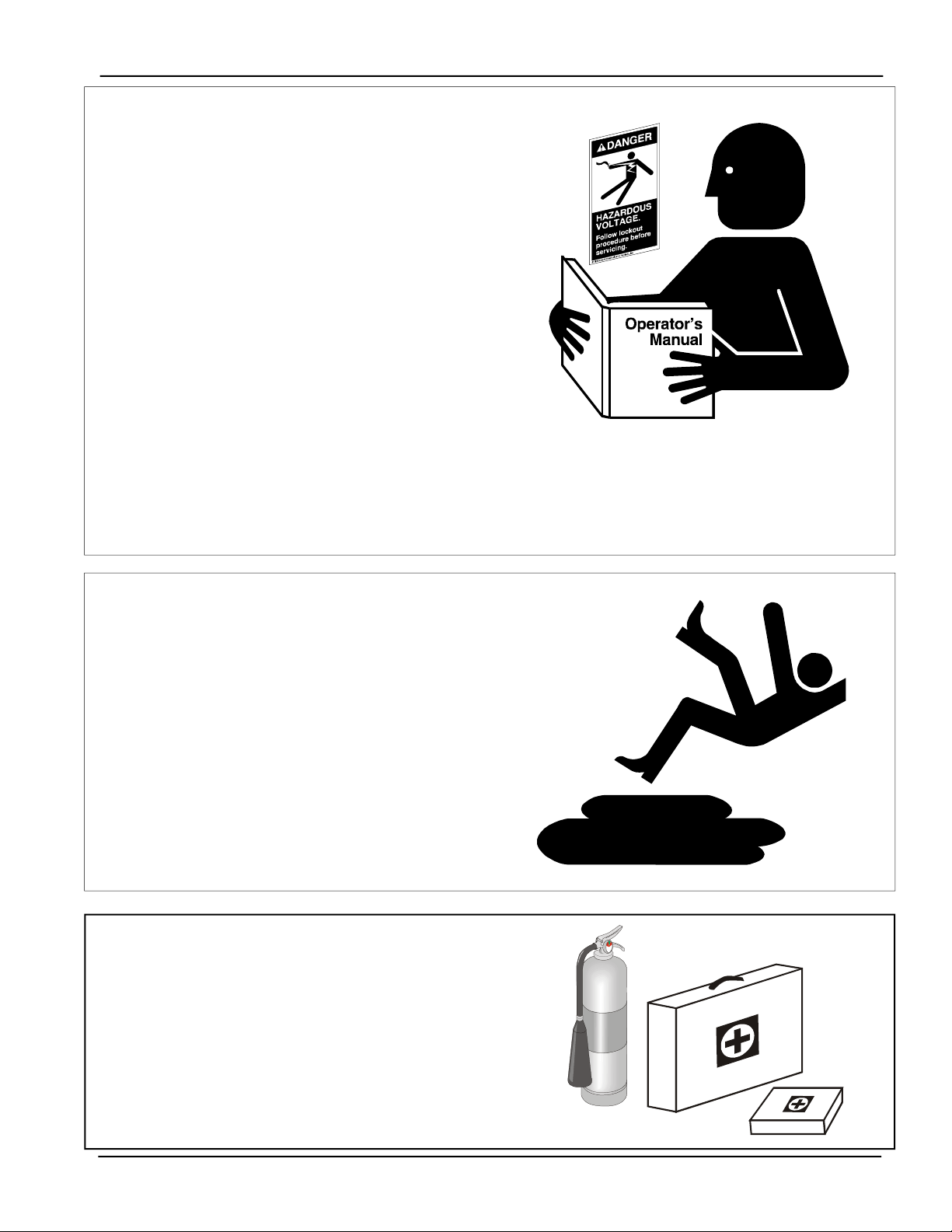
FOLLOW SAFETY INSTRUCTIONS
Carefully read all safety messages in this
manual and safety signs on your equipment.
Keep signs in good condition. Replace missing
or damaged safety signs. Be sure new equipment components and repair parts include the
current safety signs. Replacement safety signs
are available from the manufacturer.
Learn how to operate the machine and how to
use controls properly. Do not let anyone operate
without instruction.
Keep your machinery in proper working condition. Unauthorized modifications to the machine
may impair the function and/or safety and affect
machine life.
If you do not understand any part of this manual
and need assistance, contact your dealer.
SAFETY
PRACTICE SAFE MAINTENANCE
Understand service procedures before doing
work. Keep area clean and dry.
Never lubricate, service, or adjust machine while
it is in operation. Keep hands, feet, and clothing
from rotating belt and idlers.
Keep all parts in good condition and properly
installed. Fix damage immediately. Replace
worn or broken parts. Remove any build up
grease, oil, or debris.
PREP
ARE FOR EMERGENCIES
Be prepared if fire starts.
Keep a first aid kit and fire extinguisher handy.
Keep emergency numbers for doctors, ambulance
service, hospital, and fire department near your
telephone.
PNEG-1499 High / Low Thermostat
5
Page 6
SAFETY
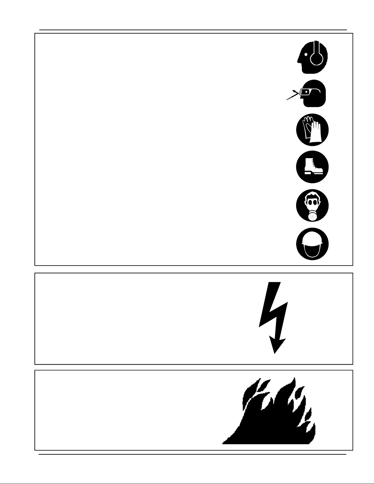
WEAR PROTECTIVE CLOTHING
Wear close fitting clothing and safety equipment
appropriate to the job.
Hearing Protection
Ear Plugs or Muffs should be worn at all times to
protect ears from high noise levels.
Safety glasses should be worn at all times to protect
eyes from debris.
Wear gloves to protect your hands from sharp edges
on plastic or steel parts.
A respirator may be needed to prevent breathing
potentially toxic fumes and dust.
Wear hard hat and steel toe boots to help protect
your head and toes from falling debris.
Eye Protection
Gloves
Steel Toe
Boots
Respirator
Hard Hat
INST
ALL
& OPERA
EQUIPMENT PROPERL
Electrical controls should be installed by a qualified
electrician and must meet the standards set by the
national electrical code and all local and state
codes.
Disconnect and lock out all power sources before
installing wires/cables or servicing equipment .
INST
ALL
& OPERA
EQUIPMENT PROPERL
Fuel supply should be installed by a qualified gas
technician and must meet local and state codes for
gaseous fuel supplies.
Disconnect and lock out all fuel sources before
servicing equipment .
TE ELECTRICAL
Y
TE GAS-FIRED
Y
6
PNEG-1499 High / Low Thermostat
Page 7

SAFETY DECALS
Safety decals should be read and understood by all people in the grain
handling area. If a decal is damaged or is missing contact:
The GSI Group, Inc.
1004 E. Illinois St.
Assumption, IL 62510
217-226-4421
A free replacement will be sent to you.
Part Number: DC-889
Size: 2.813” x 1.375”
Located on side of thermostat.
PNEG-1499 High / Low Thermostat
7
Page 8

SAFETY
Roof Damage Warning And Disclaimer
GSI DOES NOT WARRANT ANY ROOF DAMAGE CAUSED
BY EXCESSIVE VACUUM OR INTERNAL PRESSURE FROM
FANS OR OTHER AIR MOVING SYSTEMS. ADEQUATE
VENTILATION AND/OR "MAKEUP AIR" DEVICES SHOULD
BE PROVIDED FOR ALL POWERED AIR HANDLING SYSTEMS. GSI DOES NOT RECOMMEND THE USE OF DOWNWARD FLOW SYSTEMS (SUCTION). SEVERE ROOF DAMAGE CAN RESULT FROM ANY BLOCKAGE OF AIR PASSAGES. RUNNING FANS DURING HIGH HUMIDITY/COLD
WEATHER CONDITIONS CAN CAUSE AIR EXHAUST OR
INTAKE PORTS TO FREEZE.
General Safety Statements
Thank you for choosing a GSI Group product.
It is designed to give excellent performance and service for many years.
It is the plan of The GSI Group to improve its
product whenever possible and practical to do so. We
reserve the right to change, improve, and modify products at any time without obligation to make changes,
improvements, and modifications on equipment sold previously.
The principal concern of the The GSI Group Inc.
("GSI") is your safety and the safety of others associated with grain handling equipment. This manual is written to help you understand safe operating procedures,
and some of the problems that may be encountered by
the operator or other personnel.
As owner and/or operator, it is your responsibility to
know what requirements, hazards and precautions exist, and to inform all personnel associated with the equipment, or who are in the dryer area. Avoid any alterations to the equipment. Such alterations may produce
a very dangerous situation, where serious injury or death
may occur.
THIS MANUAL
AND OPERA
MOSTAT. THIS PRODUCT IS AN IDEAL
ACCESSORIY TO THE HEATERS USED FOR THE
CONDITIONING OF CORN, SOYBEANS, AND OTHER
SELECT GRAINS. ANY OTHER USE IS CONSIDERED A MISUSE OF THE PRODUCT.
DESCRIBES THE INST
TION OF A DIGITAL HIGH/LOW THER-
ALLA
TION
8
PNEG-1499 High / Low Thermostat
Page 9

Installation Instructions
1.
Mount the thermostat control on the right side of
the fan transition. Locate a suitable location on the
bin wall that will allow the power cord to reach the
heater and the control to be at eye level for easy access.
2.
Use the S-280 self-drilling screws provided in the
packaging to mount the control.
3.
Run the power cord to the heater control box and
make the connections as shown in the electrical connection section of this manual.
4.
Mount the thermostat sensor 24” to the RIGHT of
the transition. Use the C-8058 Sensor Mounting Plate
as a template.
a 2.66” and 4.00” bin sidewall.
This part has holes to match the hills of
INSTALLATION
5.
Use the S-280 screws provided to mount the C-8058
plate on the sidewall. The large hole on the plate should
be centered on a valley of the bin corrugations. The
plate should be mounted approximately in the center of
the plenum at the closest valley.
6.
Use the hole in the mounting plate as a guide and
drill a pilot hole. Once the pilot hole is drilled in the
sidewall, remove the mounting plate.
7.
With the plate removed, enlarge the pilot hole to 1/
2” diameter.
8.
Attach the Sensor of the thermostat to the mounting
plate using the C-8057 Cord Connector. The Sensor
should extend approximately 3.00” beyond the plate. If
not, then adjust the sensor length by loosening the cord
connector and moving the Sensor.
9.
Insert the Sensor into the 1/2” hole and reattach the
mounting plate using the S-280 screws.
10.
Caulk the area around the mounting plate to seal
any openings.
Mount the Sensor approximately 24” to the
RIGHT of the transition.
PNEG-1499 High / Low Thermostat
9
Page 10

ELECTRICAL CONNECTION
Standard electrical safety practices and codes
should be used when working with a heater. Refer
to the National Electric Code Standard Handbook
by the National Fire Protection Association. A quali-
fied electrician should make all wiring installations.
Thermostat Connection to Standard Terminal
Strip on heaters built prior to 2007.
1.
Connect power cord to fan control box.
2.
Connect the BLACK 120VAC power wire
to terminal 2.
3.
Connect the WHITE Neutral wire to
terminal 8.
DANGER
ALWAYS DISCONNECT AND LOCK OUT POWER
BEFORE WORKING ON OR AROUND HEATER.
4.
Connect the GREEN Stage 1 Common wire
to terminal 6.
5.
Connect the RED Stage 1 N/O wire
to the high/low light and cycle solenoid.
6.
Connect the ORANGE Stage 2 Common
wire to terminal 8.
7.
Connect the BLUE Stage 2 N/O wire to terminal 5.
10
PNEG-1499 High / Low Thermostat
Page 11

ELECTRICAL CONNECTION
Thermostat Connection to Standard Terminal
Strip on heaters built in 2007 to present.
1.
Connect power cord to fan control box.
2.
Connect the BLACK 120VAC power wire
to the ON / OFF switch. Make this connection so
this switch will also control the thermostat power.
3.
Connect the WHITE Neutral wire to
4.
Connect the GREEN Stage 1 Common wire
to terminal 6.
terminal 8.
5.
Connect the RED Stage 1 N/O wire
to the high/low light and cycle solenoid.
6.
Connect the ORANGE Stage 2 Common
wire to terminal 1.
7.
Connect the BLUE Stage 2 N/O wire to high limit
circuit on the incoming L1 power.
Note: Terminal strip may or may not be present in heater
to connect wires in thermostat circuits.
PNEG-1499 High / Low Thermostat
11
Page 12

ELECTRICAL CONNECTION
Thermostat Connection to
HF-7318 Circuit Board
1.
Connect power cord to fan control box.
2.
Connect the BLACK 120VAC power wire
to terminal 20.
3.
Connect the WHITE Neutral wire to
terminal 19.
4.
Connect the BLUE Stage 2 Common wire to
terminal 15.
5.
Connect the ORANGE Stage 2 N/O wire to
terminal 14.
6.
Connect the RED Stage 1 N/O wire to
terminal 13.
7.
Connect the GREEN Stage 1 Common wire to
terminal 12.
12
PNEG-1499 High / Low Thermostat
Page 13

Programming Set Points
Programming can be done anytime that the thermostat control is receiving power, even when the heater
is in operation.
1.
Press the SET key once to set temperature scale
mode. Use the UP or DOWN arrow key to toggle
between F for degrees Fahrenheit or C for degrees
Celsius.
2.
Press the SET key again. “S1” should now flash
at the left side of the screen. Press the UP arrow to
increase or the DOWN arrow to decrease the setpoint
to the desired temperature.
Cycle Set Point
increases above this point, the flame is reduced to
“Low Flame”.
3.
Press the SET key again. “DIF1” should now flash
at the left side of the screen. Press the UP arrow to
increase or the DOWN arrow to decrease the differential to the desired setting.
- If the plenum temperature
PROGRAMMING
Temperature Differential 2
because the temperature is greater than the High
Limit Set Point, then the temperature must fall
below the (Set Point minus Temperature Differen
tial) for the flame to come back on. Heater will
resume low flame operation.
7.
Press the SET key again. “H2” should appear on
the screen. This must read “H2” for the heater to
operate correctly. If not, use the arrow keys to scroll
through the values until the screen reads
8.
Press the SET key again.
This will end programming.
The Thermostat Control will automatically end programming if no keys are pressed for a period of 30 seconds.
Any settings that have been input to the control will be
accepted at that point.
- If the flame shuts off
“H2”.
Temperature Differential 1
because the temperature is greater than the Cycle
Set Point, then the temperature must fall below the
(Set Point minus Temperature Differential) for the
flame to come back on. Heater will resume high
flame operation.
4.
Press the SET key again. “H1” should appear on
the screen. This must read “H1” for the heater to
operate correctly. If not, use the arrow keys to scroll
through the values until the screen reads “H1”.
5.
Press the SET key again. “S2” should now flash
at the left side of the screen. Press the UP arrow to
increase or the DOWN arrow to decrease the setpoint
to the desired temperature.
High Limit Set Point
increases above this point, the flame is shut off --
“OFF Cycle”.
6.
Press the SET key again. “DIF2” should now flash
at the left side of the screen. Press the UP arrow to
increase or the DOWN arrow to decrease the differential to the desired setting.
- If the flame shuts off
- If the plenum temperature
All control settings are retained in memory. Re-programming is not necessary after power outages or disconnects unless different control settings are required.
The temperature differentials can be set from 1-30 degrees. It is recommended that these temperature differentials be set in the range of 10-15 °F for high temperature units, and 1-5 °F for low temperature units.
PNEG-1499 High / Low Thermostat
13
Page 14

PARTS
14
HF-8056 THERMOSTAT ASY HI-LO 2-STAGE DIGITAL
Key
1 1
2 2
3 2
4 12 ft
5 6
6 1
7 1
8 1
Qty
Part Number Description
HF-8055
FH-1309
FH-1310
WR-186SEOW
S-280
HF-8058
HF-8057
HF-8117
THERMOSTAT 2-STAGE DIGITAL
LOCK NUT 1/2" #401 ARL.
CONNECTOR 1/2"
WIRE CLM 18/6 SEOW CTRL CBL
SCREW SDS #10-16x5/8 HWH ZN
SENSOR MOUNTING PLATE-HILO T/S
CONNECTOR STRAIGHT CORDGRIP
THERMISTOR SENSOR - Replacement Only
PNEG-1499 High / Low Thermostat
Page 15

APPENDIX
NOTE:
Refer to Documentation provided by component manufacturer for troubleshooting and maintenance of the Thermostat Control including sensor data.
Form No. 7515006-001 Rev B.
Troubleshooting Error Messages.
E1
E2
EP
EE
CL
Appears when either the up arrow or down arrow key is pressed when not
in the programming mode.
To Correct:
pressed, replace the control.
Appears if the control settings are not properly stored in memory.
To Correct:
Appears when the probe is open, shorted, or sensing a temperature that
is out of range.
To Correct:
the probe for damage by comparing it to a known ambient temperature
between -30°F and 220°F. Replace the probe if necessary.
Appears if the EEPROM data has been corrupted.
To Correct:
Appears if calibration mode has been entered.
To Correct
Reapply power. If the CL message still appears, replace the control.
If the E1 message appears even when no keys are being
Check all settings and correct if necessary.
Check to see if the temperature is out of range. If not, check
This condition cannot be field repaired. Replace the control.
: Remove power to the control for at least five seconds.
PNEG-1499 High / Low Thermostat
15
Page 16

16
PNEG-1499 High / Low Thermostat
Page 17

Limited Warranty
The GSI Group, LLC. (“GSI”) warrants products which it manufactures to be free of defects in materials
and workmanship under normal usage and conditions for a period of 12 months after sale to the original
end-user or if a foreign sale, 14 months from arrival at port of discharge, whichever is earlier. The enduser’s sole remedy (and GSI’s only obligation) is to repair or replace, at GSI’s option and expense,
products that in GSI’s judgment, contain a material defect in materials or workmanship. Expenses
incurred by or on behalf of the end-user without prior written authorization from the GSI Warranty Group
shall be the sole responsibility of the end-user.
Warranty Extensions: The Limited Warranty period is extended for the following products:
Product Warranty Period
AP Fans and
Flooring
Cumberland
Feeding/Watering
Systems
Grain Systems
Grain Systems
Farm Fans
Zimmerman
Performer Series Direct Drive
Fan Motor
All Fiberglass Housings Lifetime
All Fiberglass Propellers Lifetime
Feeder System Pan Assemblies 5 Years **
Feed Tubes (1.75" & 2.00") 10 Years *
Centerless Augers 10 Years *
Watering Nipples 10 Years *
Grain Bin Structural Design 5 Years
Portable & Tower Dryers 2 Years
Portable & Tower Dryer Frames
and Internal Infrastructure †
3 Years
5 Years
GSI further warrants that the portable and tower dryer frame and basket, excluding all auger and auger
drive components, shall be free from defects in materials for a period of time beginning on the twelfth (12
month from the date of purchase and continuing until the sixtieth (60
th
) month from the date of purchase
* Warranty prorated from list price:
0 to 3 years – no cost to end-user
3 to 5 years – end-user pays 25%
5 to 7 years – end-user pays 50%
7 to 10 years – end user pays 75%
** Warranty prorated from list price:
0 to 3 years – no cost to end-user
3 to 5 years – end-user pays 50%
† Motors, burner components and
moving parts not included. Portable
Dryer screens included. Tower Dryer
screens not included.
th
)
(extended warranty period). During the extended warranty period, GSI will replace the frame or basket
components that prove to be defective under normal conditions of use without charge, excluding the labor,
transportation, and/or shipping costs incurred in the performance of this extended warranty.
Conditions and Limitations:
THERE ARE NO WARRANTIES THAT EXTEND BEYOND THE LIMITED WARRANTY DESCRIPTION
SET FORTH ABOVE. SPECIFICALLY, GSI MAKES NO FURTHER WARRANTY OF ANY KIND,
EXPRESS OR IMPLIED, INCLUDING, WITHOUT LIMITATION, WARRANTIES OF MERCHANTABILITY
OR FITNESS FOR A PARTICULAR PURPOSE OR USE IN CONNECTION WITH: (i) PRODUCT
MANUFACTURED OR SOLD BY GSI OR (ii) ANY ADVICE, INSTRUCTION, RECOMMENDATION OR
SUGGESTION PROVIDED BY AN AGENT, REPRESENTATIVE OR EMPLOYEE OF GSI REGARDING
OR RELATED TO THE CONFIGURATION, INSTALLATION, LAYOUT, SUITABILITY FOR A PARTICULAR
PURPOSE, OR DESIGN OF SUCH PRODUCTS.
GSI shall not be liable for any direct, indirect, incidental or consequential damages, including, without
limitation, loss of anticipated profits or benefits. The sole and exclusive remedy is set forth in the Limited
Warranty, which shall not exceed the amount paid for the product purchased. This warranty is not
transferable and applies only to the original end-user. GSI shall have no obligation or responsibility for any
representations or warranties made by or on behalf of any dealer, agent or distributor.
GSI assumes no responsibility for claims resulting from construction defects or unauthorized modifications
to products which it manufactured. Modifications to products not specifically delineated in the manual
accompanying the equipment at initial sale will void the Limited Warranty.
This Limited Warranty shall not extend to products or parts which have been damaged by negligent use,
misuse, alteration, accident or which have been improperly/inadequately maintained. This Limited Warranty
extends solely to products manufactured by GSI.
Prior to installation, the end-user has the responsibility to comply with federal, state and local codes which
apply to the location and installation of products manufactured or sold by GSI.
9101239_1_CR_rev7.DOC (revised July 2009)
Page 18

This Equipment shall be installed in accordance with the current
installation codes and applicable regulations which should be
carefully followed in all cases. Authorities having jurisdiction
should be consulted before installation occurs.
Revisions:
10/05/07 Updated all drawings and instructions for wiring Stage 1 as Cycle and Stage 2
as High Limit. Included instructions for wiring to new heaters using HH-1089E
Time Delay.
18
Revised: October 5, 2007
PNEG-1499 High / Low Thermostat
 Loading...