

Page 1
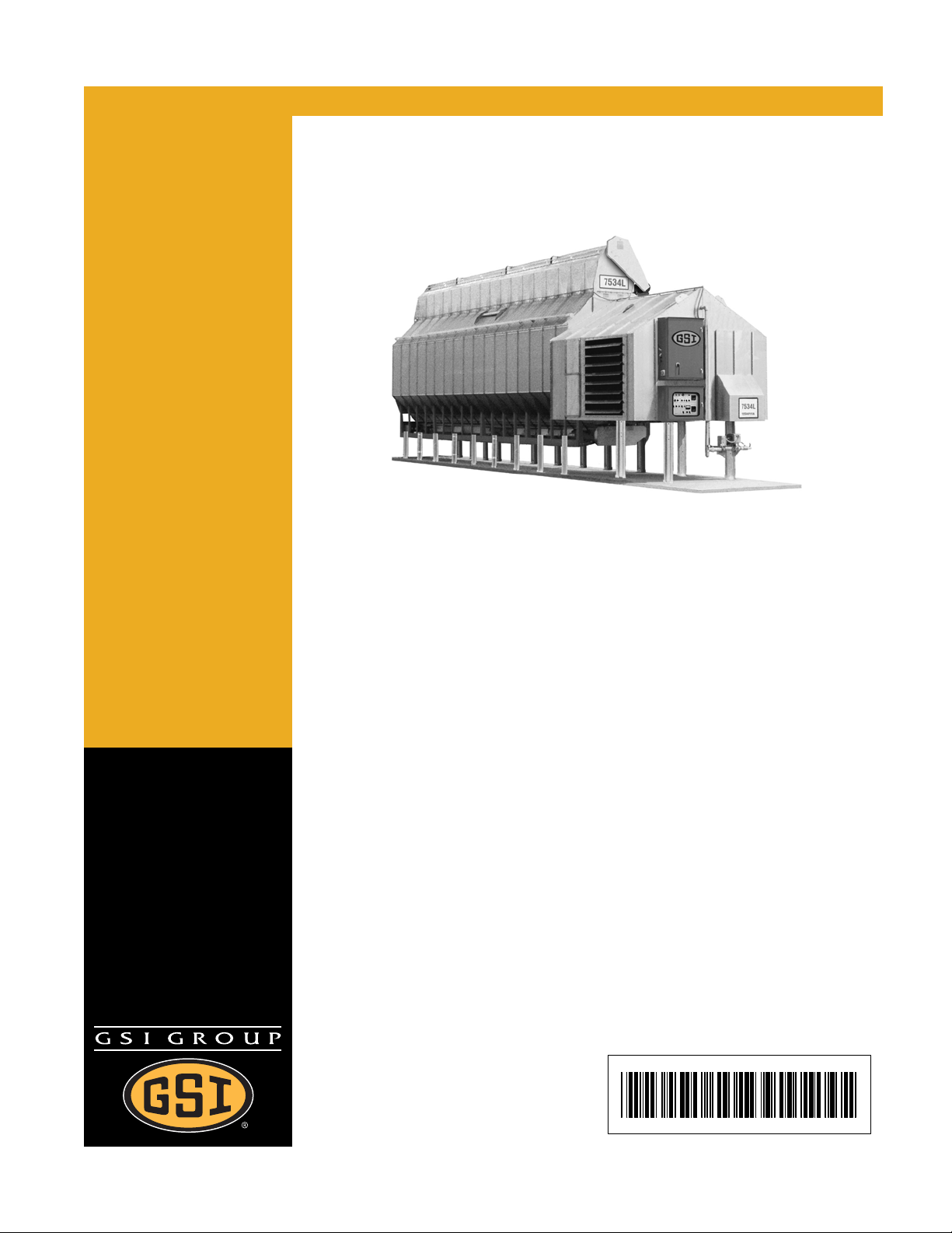
L and B Series Field Installation
Installation Guide for
Centrifugal Dryers
PNEG-1472
Date: 04-18-08
PNEG-1472
Page 2

2 PNEG-1472 L & B Series Field Installation
Page 3

Table of Contents
Contents
Chapter 1 Introduction ........................................................................................................................................ 4
Chapter 2 Safety ..................................................................................................................................................5
Safety Guidelines ............................................................................................................................... 5
Safety Instructions .............................................................................................................................. 6
Chapter 3 Safety Decals ......................................................................................................................................8
Chapter 4 Installation Instructions...................................................................................................................11
Site Selection .................................................................................................................................... 11
Foundation ................................................................................................................................. ...... 11
Legs ..................................... ................ ................ ................ ................ ................ .......................... ... 11
Dryer Assembly Instructions.............................................................................................................. 11
1. Leg Assembly................................................................................................................................ 11
2. Set Dryer Body.............................................................................................................................. 11
3. Set Fan-Heater Module................................................................................................................. 14
4. Fan-Heater Enclosure Assembly... ... ... ... ... .... ... ... .......................................... ... .... ... ... ................... 16
5. Fuel Plumbing Assembly............................................................................................................ ... 22
6. Vaporizer Plumbing Assembly ...................................................................................................... 24
7. Electrical Wiring............................................................................................................................. 26
Chapter 5 Warranty ...........................................................................................................................................29
PNEG-1472 L & B Series Field Installation 3
Page 4

1. Introduction
Thank you for choosing a GSI product. It is designed to provide excellent performance and service for
many years.
This manual describes the start-up of Vision series model dryers. When installed and operated properly
and according to specifications, this unit will provide many years of dependable service.
READ THIS MANUAL carefully to learn how to properly use and install equipment. Failure to do so could
result in personal injury or equipment damage.
INSPECT the shipment immediately upon arrival. The customer is responsible for ensuring that all
quantities are correct. The customer should report and note any damage or shortage on the bill of lading
to justify their claim to the transport company.
THIS MANUAL SHOULD BE CONSIDERED a permanent part of your equipment and should be easily
accessible when needed.
The warranty provides you the assurance that the company will back its products when defects appear
within the warranty period. In some circumstances, the company also provide s field improvements, often
without charge to the customer, even if the product is out of warranty. Should the equipment be abused,
or modified to change its performance beyond the factory specifications, the warranty will be come void
and field improvements may be denied.
4 PNEG-1472 L & B Series Field Installation
Page 5
2. Safety
Safety Guidelines
This manual contains information that is important for you, the owner/operator, to know and understand.
This information relates to protecting personal safety and preventing equipment problems. It is the
responsibility of the owner/operator to inform anyone operating or working in the area of this equipment
of these safety guidelines. To help you recognize this information, we use the symbols that are defined
below. Please read the manual and pay attention to these sections. Failure to read this manual and its
safety instructions is a misuse of the equipment and may lead to serious injury or death.
This is the safety alert symbol. It is used to alert you
to potential personal injury hazards. Obey all safety
messages that follow this symbol to avoid possible
injury or death.
DANGER indicates an imminently hazardous situation
which, if not avoided, will result in death or serious injury.
WARNING indicates a potentially hazardous situation
which, if not avoided, could result in death or serious injury.
CAUTION indicates a potentially hazardous situation which,
if not avoided, may result in minor or moderate injury.
CAUTION used without the safety alert symbol indicates a
potentially hazardous situation which, if not avoided, may
result in property damage.
NOTE indicates information about the equipment that you
should pay special attention.
PNEG-1472 L & B Series Field Installation 5
Page 6
2. Safety
Safety Instructions
Our foremost concern is your safety and the safety of others associated with this equipment. We want
to keep you as a customer. This manual is to help you understand safe operating procedures and some
problems which may be encountered by the operator and other personnel.
As owner and/or operator, it is your responsibility to know what requ irements, hazards and p recautions
exist, and to inform all personnel associated with the equipment or in the area . Safety precautions may
be required from the personnel. Avoid any alterations to the equipment. Such alterations may produce
a very dangerous situation where SERIOUS INJURY or DEATH may occur.
This equipment shall be installed in accordance with the current installation codes and applicable
regulations which should be carefully followed in all cases. Authorities having jurisdiction should be
consulted before installations are made.
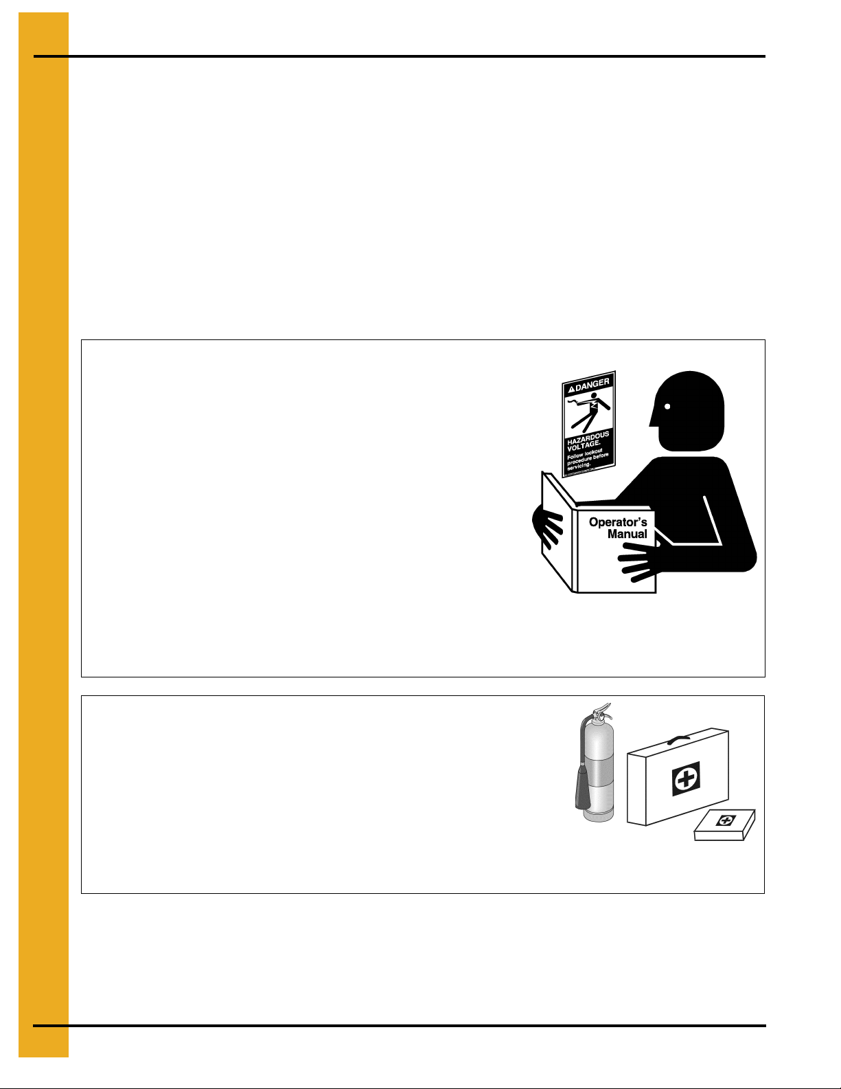
Follow Safety Instructions
Carefully read all safety messages in this manual and
safety signs on your machine. Keep signs in good
condition. Replace missing or damaged safety signs. Be
sure new equipment components and repair parts include
the current safety signs. Replacement safety signs are
available from the manufacturer.
Learn how to operate the machine and how to use controls
properly. Do not let anyone operate without instruction.
Keep your machinery in proper working condition.
Unauthorized modifications to the machine may impair
the function and/or safety and affect machine life.
If you do not understand any part of this manual or need
assistance, contact your dealer.
Prepare for Emergencies
Be prepared if fire starts.
Keep a first aid kit and fire extinguisher handy.
Keep emergency numbers for doctors, ambulance service,
hospital and fire department near your telephone.
Read and Understand Manual
Keep Emergency Equipment
Quickly Accessible
6 PNEG-1472 L & B Series Field Installation
Page 7
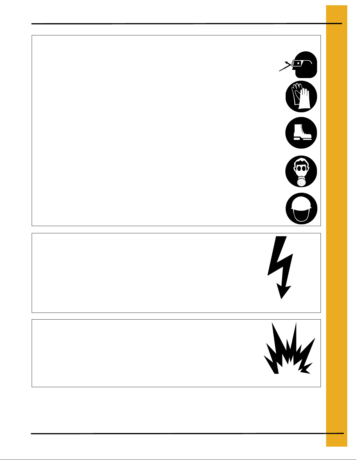
Wear Protective Clothing
Wear close fitting clothing and safety equipment appropriate
to the job.
Remove all jewelry.
2. Safety
Eye Protection
Long hair should be tied up and back.
Safety glasses should be worn at all times to protect eyes
from debris.
Wear gloves to protect your hands from sharp edges on
plastic or steel parts.
Wear steel toe boots to help protect your feet from falling
debris. Tuck in any loose or dangling shoe strings.
A respirator may be needed to prevent breathing potentially
toxic fumes and dust.
Wear hard hat to help protect your head.
Install and Operate Electrical Equipment Properly
Electrical controls should be installed by a qualified electrician
and must meet the standards set by the National Electrical Code
and all local and state codes.
Gloves
Steel Toe Boots
Respirator
Hard Hat
Disconnect and lock out all power sources before installing
wires/cables or servicing equipment.
Electric Shock Hazard
Install and Operate Gas-Fired Equipment Properly
Fuel supply should be installed by a qualified gas
technician and must meet local and state codes for
gaseous fuel supplies.
Disconnect and lock out all fuel sources before
servicing equipment.
PNEG-1472 L & B Series Field Installation 7
Explosive Gases
Page 8
3. SAFETY DECALS
The GSI Group, Inc. recommends contacting your local power company, and having a representative
survey your installation so the wiring is compatible with their system, and adequate power is supplied to
your unit. Safety decals should be read and understood by all people in the grain handling area.
If a decal is damaged or is missing contact:
The GSI Group, Inc.
1004 E. Illinois St.
Assumption, IL 62510
Ph: (217) - 226 - 4421
A free replacement will be sent to you.
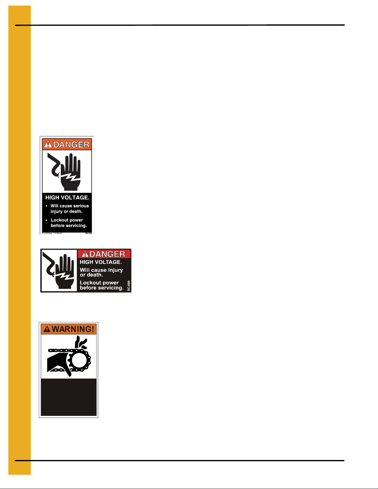
Decal DC-1224 is located in two places on the fan/heater control box.
One on the lid and one on the front of the fan heater control box.
Another location for this decal is inside the upper control box for the
dryer.
Moving parts can crush
and cut. Keep hands
clear. Do not operate
without guards in place.
Failure to do so could
result in serious injury.
DC-972
Decal DC-889 has two locations. One inside the fan/heater
control box and another on the dryer upper control box door
next to the main power disconnect.
Decal DC-972 is located on the bottom auger belt guard and the front
bearing plate (which is visible when then bottom auger belt guard is
removed). An alternate location would be at the rear of the dryer for
portable dryers equipped with the Front Discharge Option.
8 PNEG-1472 L & B Series Field Installation
Page 9
3. Safety Decals
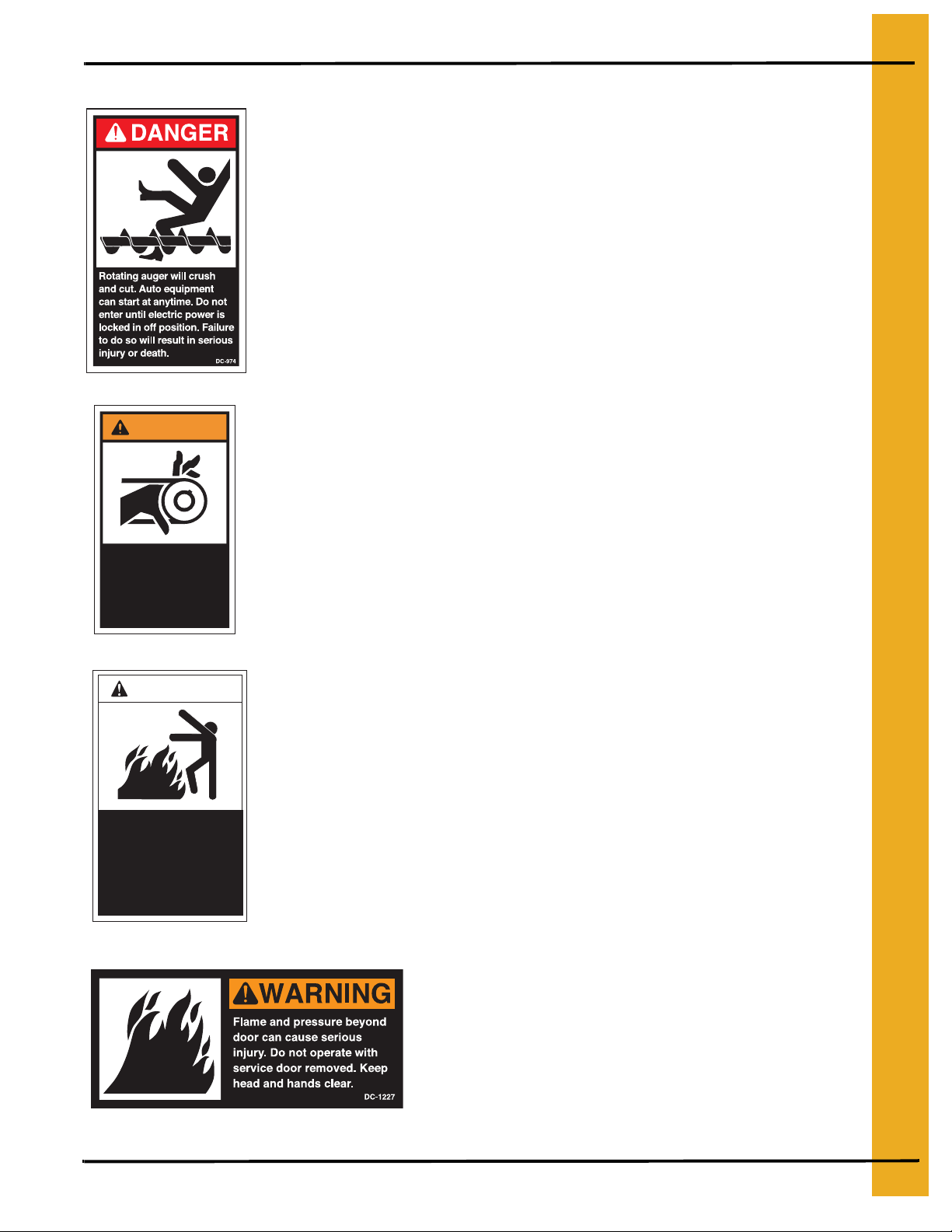
Decal DC-974 has several different locations. Two are located on the
front end panel below the fan/heater. Two are located on the rear end
panel below the rear access door. Two are located on the auger
discharge box (one on the outside top and one on the inside of the
flapper lid next to the discharge mercury switch). One more of these
decals is located inside the plenum on the rear plenum closure door just
inside the rear access door.
WARNING
Automatically controlled
belt drive can start at
anytime. Keep hands
clear. Failure to do so
could result in serious
injury.
DC-971
DANGER!
Automatic equipment can
start at any time. Do not
enter until fuel is shut off
and electrical power is
locked in off position.
Failure to do so will result
in serious injury or death.
DC-973
Decal DC-971 is located on the bottom auger belt guard and the front
bearing plate (which is visible when then bottom auger belt guard is
removed). An alternate location would be at the rear of the dryer for
portable dryers equipped with the Front Discharge Option.
Another location for decal DC-971 is the top auger belt guard
(one on the belt guard cover and one inside on the belt guard body visible
when the belt guard cover is remove).
Decal DC-973 is located on the rear plenum access door
(inside and outside).
Decal DC-1227 is located on the
fan/heater access door.
PNEG-1472 L & B Series Field Installation 9
Page 10

3. Safety Decals
WARNING
Stay clear of rotating
blade. Blade could start
automatically. Can cause
serious injury. Disconnect
power before servicing.
DC-1225
Decal DC-1229 is located on each of the
meter roll access doors.
Decal DC-1225 is located on the fan/heater
access door.
Decal DC-388 is located on the hitch tongue.
Decal DC-1249 is located on the hitch tongue.
10 PNEG-1472 L & B Series Field Installation
Page 11

4. Installation Instructions
Site Selection
Consider the grain handling system and location of storage bins and existing conveyors when selecting
dryer site, to facilitate wet grain supply and dry grain discharge to conveyors. Other considerations are
prevailing wind direction, fuel and power supply locations, noise, and convenience of control location.
Foundation
The dryer should be placed on an 8” reinforced concrete slab located in a well-drained area. The slab
should be large enough to provide working area around the dryer , with a surface elevation consistent with
other parts of the grain handling and storage systems.
Legs
Centrifugal fan dryers are supplied with a standard leg set to support the dryer body 24” high as shown
in Figure 4A (optional 36” or 48” leg sets are availble). The dryer must be anchored to the foundation
with tie-down cables or placing anchor bolts through the leg supports into the fountion.
Dryer Assembly Procedure
Note: The front end of the dryer is defined as the fan-heater end. Left and right sides are as seen when
standing behind the rear of the dryer looking forward.
1. Leg Assembly
The standard leg support package shipped with this dryer is used to support the dryer frame at 24” high.
Three to five pairs of 24” leg assemblies are used under the dryer body depending on model, and two
pairs of 47.5” leg assemblies are used under the fan-heater module.
Assemble the 24” leg sets using item #2 leg weldment, item #3 cross beam 73.25” long, and item #5
triangular gusset using hardware items A and B. Snug the hardware hand-tight but do not torque until
positioned under dryer. Be sure to assemble the cross beam with the “C” channel opening facing down.
See Figure 4A.
Assemble the 47.5” legs in a similar manner using item #1 leg weldment and item #4 cross be am 64.5”
long. Be sure to orient legs so that the .25” dia. hole in the outer leg flange is 2.5” from the bottom. Set
the 47.5” legs approximately 57.5” apart on models 6034L (C2160B), 7534L (C2175B), 1038L
(C21100B), or 40.75” on models 3020L (C2130B), and 4026L (C2140B), then assemble (4) item #6
diagonal leg brace as shown. Only hand tighten hardware at this point.
2. Set Dryer Body Module
The dryer body may be placed on the dryer foundation by rolling it into position on its transports or by
using the supplied crane brackets for lifting. The wet bin must be assembled first. See wet bin assembly
manual (PNEG-1273) included in the dryer’s literature pack.
PNEG-1472 L & B Series Field Installation 11
Page 12

4. Installation Instructions
Figure 4A Support legs.
Table 1: Leg Package
415-2895-1 Leg Package for 20’ Dryer X
415-2894-4 Leg Package for 26’ Dryer X
415-2790-4 Leg Package for 34’ & 38’ Dryer X
Item Part No. Description Qty Qty Qty
1 410-1048-9 Leg Weldment LSP 24” 6 8 10
2 401-1160-1 Cross Beam LSP 74.25” 3 4 5
3 401-1156-9 Triangular Gusset LSP 20 24 28
4 410-1793-0 Leg Weldment LSP 47.5” 4 4 4
5 401-3912-3 Cross Beam LSP 64.5” 2 2 2
6 401-4025-3 Brace, Diagonal LSP 64” 4 4 -
6 401-3956-0 Brace, Diagonal LSP 77.5” - - 4
A S-9062 Bolt, FLNGS 1/2-13x1-1/4 ZN Grade 5 150 178 206
B S-8506 Nut, FLANGWZ 1/2-13 ZN 150 178 206
12 PNEG-1472 L & B Series Field Installation
Page 13

4. Installation Instructions
If the dryer is to be set using a crane, a four point crane sling with a 10 ft minimum length must be used
to prevent excessive side pull on the crane brackets. The crane and sling should be sized to lift a
minimum of:
1. 3020L (C2130B) - 9,500 lbs
2. 4026L (C2140B) - 12,500 lbs
3. 6034L (C2160B) - 16,000 lbs
4. 7534L (C2175B) - 16,000 lbs
5. 1038L (C21100B) - 17,900 lbs
When the dryer is in position, place the 24” leg support assemb lies evenly under the dryer as shown in
Figure 4A. Attach the legs using hardware items A and B , then lower the dryer body weight onto the
supports. Level and shim the dryer legs as required so that each leg is sharing the weight of the dryer.
The leg support assembly hardware can now be tightened.
The dryer body transport kit should now be removed. This includes the drop axle weldments and
wheels, hitch welment (6), hitch brace support (13), hitch brackets (8 & 9), hitch diagonal braces (11 &
12), and diagonal attaching channels (10). See Figure 4B.
Figure 4B Remove transport items.
PNEG-1472 L & B Series Field Installation 13
Page 14

4. Installation Instructions
3. Set Fan-Heater Module
The fan-heater module will require a crane to set into position. Crane lifting brackets are supplied on
this module. A four-point crane sling with a minimum length of 10 ft must be used to prevent excessive
side pull on the crane brackets. The crane and sling should be sized to lift a minimum of 4,000 lbs for
the 3020L (C2130B) and 4026L (C2140B) models or 6,000 lbs for 6034L (C2160B), and 7534L
(C2175B) models, or 9,000 lbs for 1038L (C21100B) models.
Before setting the fan-heater module, the following instructions should be followed.
• Remove any parts or packages shipped on or in the fan-heater or dryer body modules.
• If the dryer is equipped with a vaporizer for LP fuel, locate the vaporizer coil and vaporizer
support bracket and place them inside the dryer body upper plenum.
• Check to see that the mating faces of the dryer body and fan-heater module are clear of
conduits, sensors, or bolts which may interfere with the mating of the two modules.
• Place the 47.5” leg set on the foundation approx. 6 ft in front of the dryer body module.
The fan-heater module may now be lifted onto the leg set. Position the module so that the front wall of
the fan-heater module is flush with the front flange of the front legs. Using the 1/2”-13 hardware supplied
with the legs, attach the leg to the module through the two inside holes of each leg weldment. Note that
the fan-heater module should still be a few feet away from the dryer body at this point. Tighten all leg
hardware at this time.
Locate the fan-heater module hardware package and be prepared to install the 5/16” flanged or 5/16”
self tapping hardware. Make another visual inspection of the dryer and fan-heater mating surfaces for
any interferences, then lift the fan-heater with its leg sets attached into place to mate with the dryer body.
Aligning the holes in the rear floor frame channel of the fan-heater module with the holes in the front dryer
body gusset plates is the most convenient place to check for correct positioning (see Figure 4D). Install
hardware in these holes to maintain alignment, then shim and level the fan-heater module leg as
required to align and install hardware in the vertical rows of attaching holes and the row of hardware
down the roof slope.
14 PNEG-1472 L & B Series Field Installation
Page 15

4. Installation Instructions
Figure 4C Dryer dimensions - 6034L (C2160B) shown.
PNEG-1472 L & B Series Field Installation 15
Page 16

4. Installation Instructions
Figure 4D Alignment of Fan-Heater Module to Body Module.
4. Fan-Heater Enclosure Assembly (6034L, 7534L, 1038L, C2160B, C2175B,
C21100B)
The 6034L (C2160B), 7534L (C2175B), and 1038L (C21100B) model fan-heater enclosures are ship ped
unassembled to the module in order to maintain an 8 ft shipping width. Field assemble following these
steps and refer to Figures 4E, 4F, 4G, and 4H.
1. Remove the louver assemblies from their shipping placement on the fan-heater module and discard
the shipping brackets.
2. Locate (6) floor frame extension channels (item #1 401-3914-9) and insert them inside the fan
module frame channels (see Figures 4E). Note that the fan-heater floor hardware will need to
be removed then reinstalled after channels are in place. Attach using the self tapping 5/16”
hardware (S-7221).
3. Locate items #4 (401-3910-7) and #5 (401-3911-5) reclaimer floor panels and position in place over
the floor frame extension channels. Attach using self tapping 5/16” hardware (S-7221).
4. Install items #9 (401-3910-9), #10 (401-3908-1), and #11 (401-3997-4) as shown. From this step
on it is highly recommended that the hardware be installed only loosley, allowing the wall
sheets to move slightly for aligning parts.
5. Install items #26 (401-3944-6) and #17 (401-3943-8) reclaimer end panels as shown in Figure 4E.
6. Install items #8 (401-3915-6), #2 (401-3941-2), and #3 (401-3942-0) fan reclaimer side panels
shown in Figure 4E. Note that the side panels should slip under the roof panels on the fan-
16 PNEG-1472 L & B Series Field Installation
Page 17

4. Installation Instructions
heater module.
7. Install (2) item #13 (401-3850-5) outer roof frame channels as shown in Figure 4E.
8. Install (2) item #15 (401-3945-3) reclaimer roof panels as shown in Figure 4E.
9. Install (2) item #7 louver assemblies with the adjusting screw located at the bottom. Untie the
adjusting screw and feed it through the hole located in the reclaimer floor panel. It will be
necessary to remove them reinstall the handle weldment in order to do this.
10.Install (2) item #14 (401-3998-2) fan reclaimer side panels-short, (2) item #12 (401-3968-5)
sidewall braces, (2) item #18 (401-3996-6) door frame channeld, (2) item #6 (401-3995-8) fanheater access doors and door latches as shown in Figure 4E.
11.All attaching hardware may now be tightened.
PNEG-1472 L & B Series Field Installation 17
Page 18

4. Installation Instructions
Figure 4E Fan-Heater enclosure layout.
18 PNEG-1472 L & B Series Field Installation
Page 19

4. Installation Instructions
Table 2: Fan-Heater Enclosure Parts
Item Part No. Description Qty
1 401-3914-9 CHANNEL - FLOOR FRAME EXT 6
2 401-3941-2 PANEL - FAN RECLAIMER - FRONT SIDE - RH 1
3 401-3942-0 PANEL - FAN RECLAIMER - FRONT SIDE - RH 1
4 401-3910-7 PANEL - RECLAIMER FLOOR - RH 1
5 401-3911-5 PANEL - RECLAIMER FLOOR - LH 1
6 401-3995-8 DOOR FAN-HEATER ACCESS 2
7 415-2808-4 LOUVER ASSY 2
8 401-3915-6 PANEL - FAN RECLAIMER SIDE 2
9 401-3909-9 PANEL - LOWER RECLAIMER - LH 1
10 401-3908-1 PANEL - LOWER RECLAIMER - RH 1
11 401-3997-4 PANEL - UPPER RECLAIMER CLOSURE 2
12 401-3968-5 CHANNEL - SIDE WALL BRACE 2
13 401-3850-5 CHANNEL - OUTER ROOF FRAME 2
14 401-3998-2 PANEL FAN RECLAIMER SIDE SHORT 2
15 401-3945-3 PANEL - RECLAIMER - ROOF 6
16 401-3944-6 PANEL - RECLAIMER END - LH 1
17 401-3943-8 PANEL - RECLAIMER END - RH 1
18 401-3996-6 CHANNEL DOOR FRAME 4
19 025-1112-9 DOOR LATCH 2
A S-7221 SCREW, SMSAB 5/16 x 3/4 HWH GR2 B S-3611 NUT, FLANGWZ 5/16-18 ZN YDP C S-6606 BOLT, FLNGS 5/16-18 x 3/4 ZN GR5 -
PNEG-1472 L & B Series Field Installation 19
Page 20

4. Installation Instructions
Figure 4F Louver adjusting screw.
20 PNEG-1472 L & B Series Field Installation
Page 21

4. Installation Instructions
Figure 4G Fan-Heater enclosure side view.
PNEG-1472 L & B Series Field Installation 21
Page 22

4. Installation Instructions
Figure 4H Door assembly.
22 PNEG-1472 L & B Series Field Installation
Page 23

4. Installation Instructions
5. Fuel Plumbing Assembly
The fuel inlet manifold assembly has been shipped pre-assembled. LP model dryers also include a
vaporizer plumbing assembly and will require assembly. Use a teflon paste pipe sealer on fuel pipe
threads.
The fuel manifold assembly should be assembled as follows:
1. Install support bracket 401-3946-1 on the underside of the front frame channel of the fan-heater
module directly beneath the existing plumbing on the fan-heater module using 5/16” bolt (S-6606)
and 5/16” nut (S-3611). See Figure 4I.
2. Install connecting pipe assembly D04-0419 to lower pipe coupler on the fan-heater module.
Secure connecting pipe to bracket installed in step 1 with U-bolt (090-1485-3).
3. Install support bracket 401-3946-1 loosely to the manifold assembly next to the Maxon valve with
U-bolt (090-1485-3). See Figure 4I. Lift the manifold assembly in place and connect the union.
Adjust the support bracket so that it lines up with the holes in the support leg and install using 5/
16” bolts (S-6606) and 5/16” nuts (S-3611).
4. Now fully tighten the union that was connected in step 3.
5. Install conduit assembly D04-0483 to the unilet “T” on the 2 inch valve. Connect the white wire to
one lead of each valve. Connect the black/white wire to the remaining lead of the 1 inch valve.
Connect the brown/white wire to the remaining lead of the 2 inch valve.
6. Install the pressure gauges as shown in Figure 4I. Use a teflon paste pipe sealer on fuel pipe
threads.
7. The Natural Gas supply line may now be installed. NG should be supplied at a regulated pressure
of 10 psi. If the fuel supply is liquid propane, see the following instructions for vaporizer plumbing
installation. If an external vaporizer is used, a propane vapor supply line regulated to 10 psi may
be installed at this time.
PNEG-1472 L & B Series Field Installation 23
Page 24

4. Installation Instructions
Figure 4I Fuel manifold installation.
24 PNEG-1472 L & B Series Field Installation
Page 25

4. Installation Instructions
6. Vaporizer Plumbing Assembly (LP models only)
The vaporizer plumbing assembly is installed as follows (LP models only). Refer to Fig ures 4J, 4K, and
4L.
1. Install the vaporizer assembly and vaporizer support bracket into dryer heating plenum.
2. Starting from the vaporizer, assemble the pipe subassemblies. Fully tighten all pipe joints as you
proceed. Use a teflon paste pipe sealer on fuel pipe threads.
3. See installation Step 7, Electrical Wiring, for attaching and wiring vaporizer conduit assembly.
4. The liquid propane supply line may now be attached. Propane should be supplied at tank pressure
to the vaporizer plumbing inlet ball valve.
Figure 4J Vaporizer plumbing for 3020L (C2130B), and 4026L (C2140B).
PNEG-1472 L & B Series Field Installation 25
Page 26

4. Installation Instructions
Figure 4K Vaporizer plumbing for 6034L (C2160B), and 7534L (C2175B).
Figure 4L Vaporizer plumbing for 1038L (C21100B).
26 PNEG-1472 L & B Series Field Installation
Page 27

4. Installation Instructions
7. Electrical Wiring
The dryer modules are shipped with the wiring as complete as possible within each module. The
following wiring must be completed in the field when mating the dryer body with the fan-heater module.
1. Load Motor - The rear-fill load auger motor conduit is shipped attached to the fan-heater module
roof. Remove the conduit shipping ties and attach the conduit junction box to the upper right hand
side of the front dryer panel using (4) self-tapping screws. Route the flex conduit to the unload
motor and wire motor for the appropriate supply voltage. Attach the Fill Switch box to the Fill
Paddle shaft. Connect the SJO cord to orange and yellow wires inside the Top Auger Conduit
junction box.
2. Unload Motor - The conduit for the unload motor is found tied to the rear fan-heater frame channel
under the module. Route the flex conduit to the unload motor and wire motor for the appropriate
supply voltage.
3. SCR Motor - The conduit for the SCR motor is found tied to the rear fan-heater frame channel under
the module. Route the flex conduit to the SCR motor and wire motor.
4. Sensors - Find the flex conduit tied to the right side of the dryer body module and route to the Upper
Control Box and connect wires to the terminal strip as shown in Figure 4M.
5. Maxon Valve and Fuel Manifold - Route these two conduit to the Upper Control Box and connect
the Maxon valve wires to the lower terminal strip at the gray and white terminals labeled for the
Maxon valve. Connect fuel manifold wire to the upper terminal strip as shown in Figure 4M.
6. Liquid Solenoid Valve and Vapor Hi-Limit - If the dryer is equipped with a LP vaporizer the
Vaporizer Conduit must be assembled to the Vapor Hi-Limit Thermostat and the Liquid Solenoid
Valve. Connect the thermostat and valve in series and route the conduit to the upper control box.
Connect wire to the appropriate terminals as shown in Figure 4M.
PNEG-1472 L & B Series Field Installation 27
Page 28

4. Installation Instructions
Figure 4M Upper control box terminal wiring.
28 PNEG-1472 L & B Series Field Installation
Page 29

7. Warranty
The GSI Group, Inc. Warranty
THE GSI GROUP, INC. (GSI) WARRANTS ALL PRODUCTS WHICH IT MANUFACTURES TO BE
FREE OF DEFECTS IN MATERIAL AND WORKMANSHIP UNDER NORMAL USAGE AND
CONDITIONS FOR A PERIOD OF 12 MONTHS AFTER RETAIL SALE TO THE ORIGINAL END USER.
THE PURCHASER’S SOLE REMEDY AND GSI’S ONLY OBLIGATION SHALL BE TO REPAIR OR
REPLACE, AT GSI’S OPTION AND EXPENSE, PRODUCTS THAT, IN GSI’S SOLE JUDGMENT,
CONTAIN A MATERIAL DEFECT DUE TO MATERIALS OR WORKMANSHIP. ALL DELIVERY AND
SHIPMENT CHARGES TO AND FROM GSI’S FACTORY WILL BE PURCHASER’S RESPONSIBILITY.
EXPENSES INCURRED BY OR ON BEHALF OF THE PURCHASER WITHOUT PRIOR WRITTEN
AUTHORIZATION FROM AN AUTHORIZED EMPLOYEE OF GSI SHALL BE THE SOLE
RESPONSIBILITY OF THE PURCHASER.
EXCEPT FOR THE LIMITED WARRANTY EXPRESSED ABOVE, GSI MAKES NO FURTHER
WARRANTY OF ANY KIND, EXPRESS OR IMPLIED, INCLUDING, WITHOUT LIMITATION,
WARRANTIES OF MERCHANTABILITY OR FITNESS FOR A PARTICULAR PURPOSE
OR USE IN CONNECTION WITH (I) PRODUCT MANUFACTURED OR SOLD BY GSI OR (II) ANY
ADVICE, INSTRUCTION, RECOMMENDATION OR SUGGESTION PROVIDED BY AN AGENT,
REPRESENTATIVE OR EMPLOYEE OF GSI REGARDING OR RELATED TO THE CONFIGURATION,
INSTALLATION, LAYOUT, SUITABILITY FOR A PARTICULAR PURPOSE, OR DESIGN OF
SUCH PRODUCTS.
GSI SHALL NOT BE LIABLE FOR ANY DIRECT, INDIRECT, INCIDENTAL OR CONSEQUENTIAL
DAMAGES, INCLUDING, WITHOUT LIMITATION, LOSS OF ANTICIPATED PROFITS OR BENEFITS.
PURCHASER’S SOLE AND EXCLUSIVE REMEDY IS AS SET FORTH IN THE LIMITED WARRANTY
EXPRESSED ABOVE, WHICH SHALL NOT EXCEED THE AMOUNT PAID FOR THE PRODUCT
PURCHASED. THIS WARRANTY IS NOT TRANSFERABLE AND APPLIES ONLY TO THE ORIGINAL
PURCHASER. GSI SHALL HAVE NO OBLIGATION OR RESPONSIBILITY FOR ANY
REPRESENTATIONS OR WARRANTIES MADE BY OR ON BEHALF OF ANY DEALER, AGENT OR
DISTRIBUTOR OF GSI.
GSI ASSUMES NO RESPONSIBILITY FOR CLAIMS RESULTING FROM ERECTION DEFECTS OR
UNAUTHORIZED MODIFICATIONS TO PRODUCTS WHICH IT MANUFACTURED. MODIFICATIONS
TO PRODUCTS NOT SPECIFICALLY DELINEATED IN THE MANUAL ACCOMPANYING THE
EQUIPMENT AT INITIAL SALE WILL NULLIFY THE PRODUCT WARRANTY THAT MIGHT HAVE
BEEN OTHERWISE AVAILABLE.
THE FOREGOING WARRANTY SHALL NOT EXTEND TO PRODUCTS OR PARTS WHICH HAVE
BEEN DAMAGED BY NEGLIGENT USE, MISUSE, ALTERATION OR ACCIDENT. THIS WARRANTY
EXTENDS SOLELY TO ONLY PRODUCTS MANUFACTURED BY GSI. THIS WARRANTY IS
EXCLUSIVE AND IN LIEU OF ALL OTHER WARRANTIES EXPRESS OR IMPLIED. GSI RESERVES
THE RIGHT TO MAKE DESIGN OR SPECIFICATION CHANGES AT ANY TIME.
PRIOR TO INSTALLATION, PURCHASER HAS THE RESPONSIBILITY TO COMPLY WITH ALL
FEDERAL, STATE AND LOCAL CODES WHICH MAY APPLY TO THE LOCATION AND
INSTALLATION OF PRODUCTS MANUFACTURED OR SOLD BY GSI.
PHLEGAL: #1832020 v1 (139LG01!.DOC) (revised December 2005)
PNEG-1472 L & B Series Field Installation 29
Page 30

This equipment shall be installed in accordance with
the current installation codes and applicable
regulations which should be carefully followed in all
cases. Authorities having jurisdiction should be
consulted before installations are made.
Copyright © 2008 by GSI Group
Printed in the USA
GSI Group
1004 E. Illinois St.
Assumption, IL 62510-0020
Phone: 1-217-226-4421
Fax: 1-217-226-4420
www.grainsystems.com
 Loading...