

Page 1
PNEG-1460
6', 7' and 9' Bulk Feed Tank
BFT Series and GHT Series
Assembly Manual
PNEG-1460
Date: 09-25-13
Page 2

All information, illustrations, photos and specifications in this manual are based on the latest
information available at the time of publication. The right is reserved to make changes at any
time without notice.
2 PNEG-1460 6', 7' and 9' Bulk Feed Tank BFT Series and GHT Series
Page 3

Table of Contents
Contents
Chapter 1 Introduction .......................................................................................................................................... 5
Chapter 2 Safety ..................................................................................................................................................... 6
Safety Guidelines .................................................................................................................................. 6
General Safety Statement ..................................................................................................................... 7
Safety Instructions ..................... ... .... .......................................... ... ... ..................................................... 8
Safety Sign-Off Sheet ......................................................................................................................... 10
Proper Storage of Grain Bin/Silo Materials Prior to Construction ....................................................... 11
Chapter 3 Decals .................................................................................................................................................. 12
Chapter 4 General Information ........................................................................................................................... 13
Bulk Feed Tank Assembly Manual General Instructions .............................. ... ... ................................ 13
Chapter 5 Foundation .......................................................................................................................................... 15
Chapter 6 Sidewall Assembly ............................................................................................................................. 21
Tank Sidewalls ....................................... ... ... .... ... .......................................... ... ... .... ............................ 21
Caulking Detail .................................................................................................................................... 22
Sidewall Sheet Orientation ..................... ... ... .... ... ... .......................................... ... .... ... ......................... 23
Chapter 7 Roof ..................................................................................................................................................... 26
Sealed Roof Panels Installation .......................................................................................................... 26
Peak Ring Collar to Roof Panels ......................................................................................................... 28
Chapter 8 Optional BFT Ladder Assembly ........................................................................................................ 29
Starter Bracket Installation .................................................................................................................. 30
Sidewall and Roof Ladder Installation ................................................................................................. 31
Roof Ladder Support Bracket Installation ........................................................................................... 32
Ladder Standoff Installation ................................................................................................................ 37
Ladder Section Assembly ................................................................................................................... 38
Ladder Support Detail ......................................................................................................................... 39
Ladder Decal Application .................................................................................................................... 39
Chapter 9 Ladder Handrails ................................................................................................................................ 40
Handrail Installation for Ladder System Without Safety Cage ............................................................ 40
Chapter 10 Safety Cage ....................................................................................................................................... 48
Ladder System With Safety Cage ..................................................................................................... 48
Safety Cage Hoop Assembly ............................................................................................................. 50
Safety Cage Installation ..................................................................................................................... 52
Chapter 11 Roof Cap and Ground Control ........................................................................................................ 55
Roof Cap and Ground Control Instructions ....................................................................................... 55
Chapter 12 Hopper Assembly ...................................................................................................
Hopper Sheets ................................................................................................................................... 61
Reinforcement Angles .................................................................................................................... ... 64
Hopper Collar .................................................................................................................................... 65
Chapter 13 Legs and Leg Bracing ...................................................................................................................... 68
Tank Legs and Leg Braces ............................. ... ... ... .... ... ... ... .... ... ... ... ... ............................................. 68
Bracing Hole Layout .......... .......................................... ... ... ... .......................................... ... .... ... ... ... ... 72
Hopper to Leg Horizontal Bracing ..................................................................................................... 75
.......................... 61
Chapter 14 Raising Bin ........................................................................................................................................ 77
Raising Bin to Set on Foundation ...................................................................................................... 77
Bin Grounding Instructions .......................................... ... ... ... .... ... ... ... ................................................ 80
Chapter 15 Pneumatic Fill Kit ............................................................................................................................. 81
Pneumatic Fill Kit Assembly ....... .... ... .......................................... ... ... ... .... ... ... ... .... ... ... ... ... ................ 81
Roof Panel .................................. .......................................... ................................................. ............ 82
PNEG-1460 6', 7' and 9' Bulk Feed Tank BFT Series and GHT Series 3
Page 4

Table of Contents
Chapter 16 Parts List ........................................................................................................................................... 83
6' Diameter 60° Hopper Bin Specifications ........................................................................................ 84
6' Diameter 60° Hopper Bin Hardware Specifications ....................................................................... 86
7' Diameter 67° Hopper Bin Specifications ........................................................................................ 88
7' Diameter 67° Hopper Bin Hardware Specifications ....................................................................... 90
7' Diameter 45° Hopper Bin Specifications ........................................................................................ 92
7' Diameter 45° Hopper Bin Hardware Specifications ....................................................................... 94
9' Diameter 60° Hopper Bin Specifications ........................................................................................ 96
9' Diameter 60° Hopper Bin Hardware Specifications ....................................................................... 98
9' Diameter 45° Hopper Bin Specifications ...................................................................................... 100
9' Diameter 45° Hopper Bin Hardware Specifications ..................................................................... 102
Chapter 17 Warranty .......................................................................................................................................... 105
4 PNEG-1460 6', 7' and 9' Bulk Feed Tank BFT Series and GHT Series
Page 5

1. Introduction
READ THIS MANUAL carefully to learn how to properly use and install equipment. Failure to do so could
result in personal injury or equipment damage.
INSPECT the shipment immediately upon arrival. The customer is responsible for ensuring that all
quantities are correct. The customer should report and note any damage or shortage on the bill of
lading to justify their claim to the transport company.
THIS MANUAL SHOULD BE CONSIDERED a permanent part of your equipment and should be easily
accessible when needed.
This warranty provides you the assurance that the company will back its products when defects appear
within the warranty period. In some circumstances, the company also provides field improvements, often
without charge to the customer, even if the product is out of warranty. Should the equipment be abused,
or modified to change its performance beyond the factory specifications, the warranty will become void
and field improvements may be denied.
PNEG-1460 6', 7' and 9' Bulk Feed Tank BFT Series and GHT Series 5
Page 6

2. Safety
This is the safety alert symbol. It is used to alert you
to potential personal injury hazards. Obey all safety
messages that follow this symbol to avoid possible
injury or death.
WARNING indicates a hazardous situation which, if not
avoided, could result in death or serious injury.
CAUTION, used with the safety alert symbol, indicates a
hazardous situation which, if not avoided, could result in
minor or moderate injury.
NOTICE is used to address practices not related to
personal injury.
DANGER indicates a hazardous situation which, if not
avoided, will result in death or serious injury.
Safety Guidelines
This manual contains information that is important for you, the owner/operator, to know and understand.
This information relates to protecting personal safety and preventing equipment problems. It is the
responsibility of the owner/operator to inform anyone operating or working in the area of this equipment
of these safety guidelines. To help you recognize this information, we use the symbols that are defined
below. Please read the manual and pay attention to these sections. Failure to read this manual and its
safety instructions is a misuse of the equipment and may lead to serious injury or death.
DANGER
WARNING
CAUTION
NOTICE
6 PNEG-1460 6', 7' and 9' Bulk Feed Tank BFT Series and GHT Series
Page 7

2. Safety
This product has sharp edges, which may cause serious injury. To avoid injury, handle
sharp edges with caution and always use proper protective clothing and equipment.
General Safety Statement
Our foremost concern is your safety and the safety of others associated with grain handling equipment.
This manual is to help you understand safe operating procedures and some problems that may be
encountered by the operator and other personnel.
As owner and/or operator, you are responsible to know what requirements, hazard s, and precautions exist
and inform all personnel associated with the equipment or in the area. Safety precautions may be required
from the personnel. Avoid any alterations to the equipment, which may produce a very dangerous
situation, where SERIOUS INJURY or DEATH may occur.
You should consider the location of the bin site relative to power line locations or electrical transmission
equipment. Contact your local power company to review your installation plan or for information
concerning required equipment clearance. Clearance of portable equipment that may be taken to the bin
site should also be reviewed and considered. Any electrical control equipment in contact with the bin
should be properly grounded and installed in accordance with National Electric Code provisions and other
local or national codes.
This product is intended for the use of grain storage only. Any other use is a misuse of the product.
Sidewall bundles or sheets must be stored in a safe manner. The safest method of storing sidewall
bundles is laying horizontally with the arch of the sheet upward, like a dome. Sidewall sheets stored on
edge must be secured so that they cannot fall over and cause injury. Use care when handling and moving
sidewall bundles.
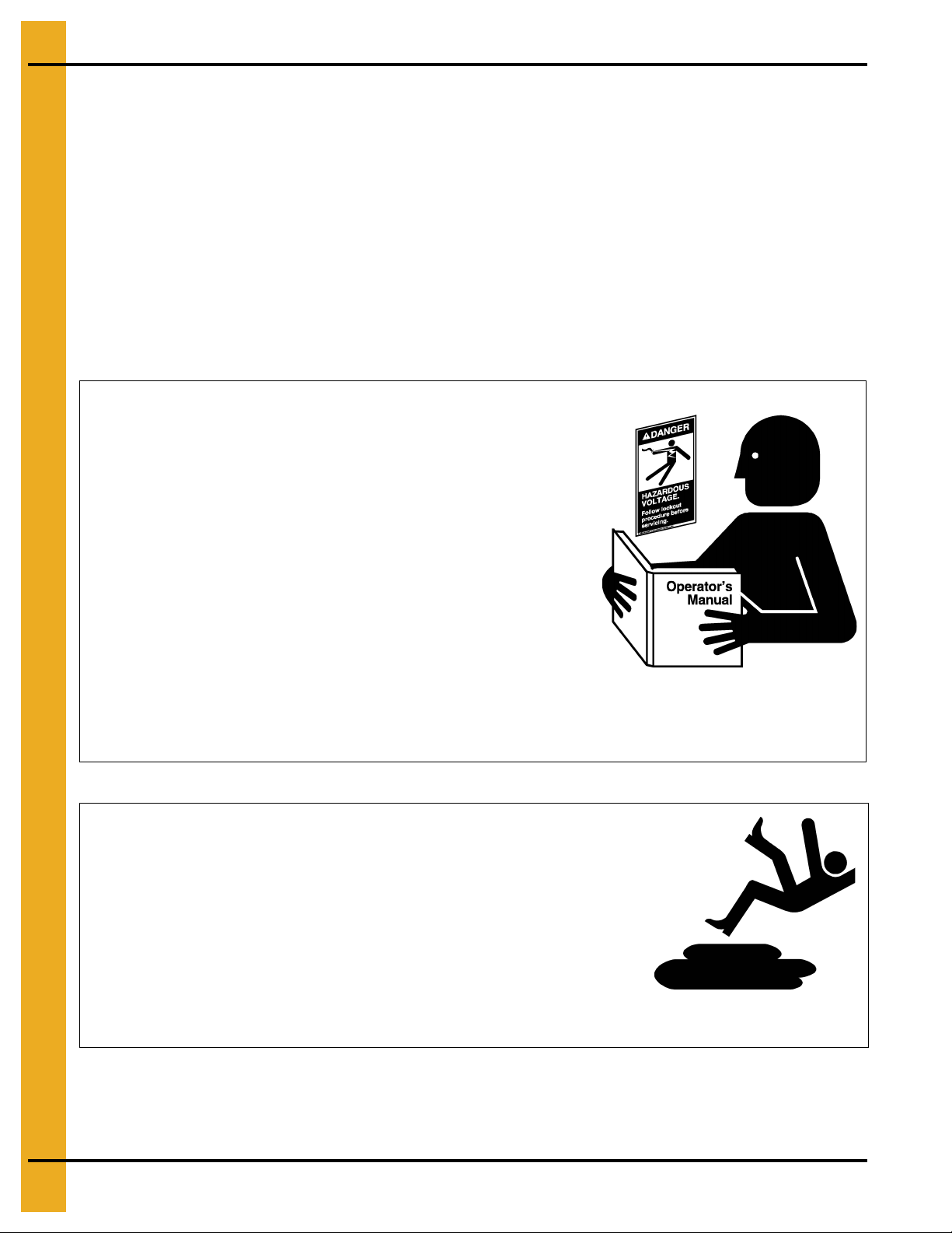
Personnel operating or working around equipment should read this manual. This manual must be
delivered with equipment to its owner. Failure to read this manual and its safety instructions is a
misuse of the equipment.
PNEG-1460 6', 7' and 9' Bulk Feed Tank BFT Series and GHT Series 7
Page 8
2. Safety
Follow Safety Instructions
Carefully read all safety messages in this manual and
safety signs on your machine. Keep signs in good
condition. Replace missing or damaged safety signs. Be
sure new equipment components and repair parts include
the current safety signs. Replacement safety signs are
available from the manufacturer.
Learn how to operate the machine and how to use controls
properly. Do not let anyone operate without instruction.
Keep your machinery in proper working condition.
Unauthorized modifications to the machine may impair
the function and/or safety and affect machine life.
If you do not understand any part of this manual or need
assistance, contact your dealer.
Read and Understand Manual
Practice Safe Maintenance
Understand service procedures before doing work. Keep area
clean and dry.
Never lubricate, service, or adjust machine while it is in operation.
Keep hands, feet, and clothing away from rotating parts.
Keep all parts in good condition and properly installed. Fix
damage immediately . Replace worn or broken p arts. Remove any
built-up grease, oil, and debris.
Maintain Equipment
and Work Area
Safety Instructions
Our foremost concern is your safety and the safety of others associated with this equipment. We want to
keep you as a customer. This manual is to help you understand safe operating procedures and some
problems that may be encountered by the operator and other personnel.
As owner and/or operator, it is your responsibility to know what requirements, hazards, and precautions
exist, and to inform all personnel associated with the equipment or in the area. Safety precautions may be
required from the personnel. Avoid any alterations to the equipment. Such alterations may p roduce a very
dangerous situation where SERIOUS INJURY or DEATH may occur.
This equipment shall be installed in accordance with the current installation codes and applicable
regulations, which should be carefully followed in all cases. Authorities having jurisdiction should be
consulted before installations are made.
8 PNEG-1460 6', 7' and 9' Bulk Feed Tank BFT Series and GHT Series
Page 9
2. Safety
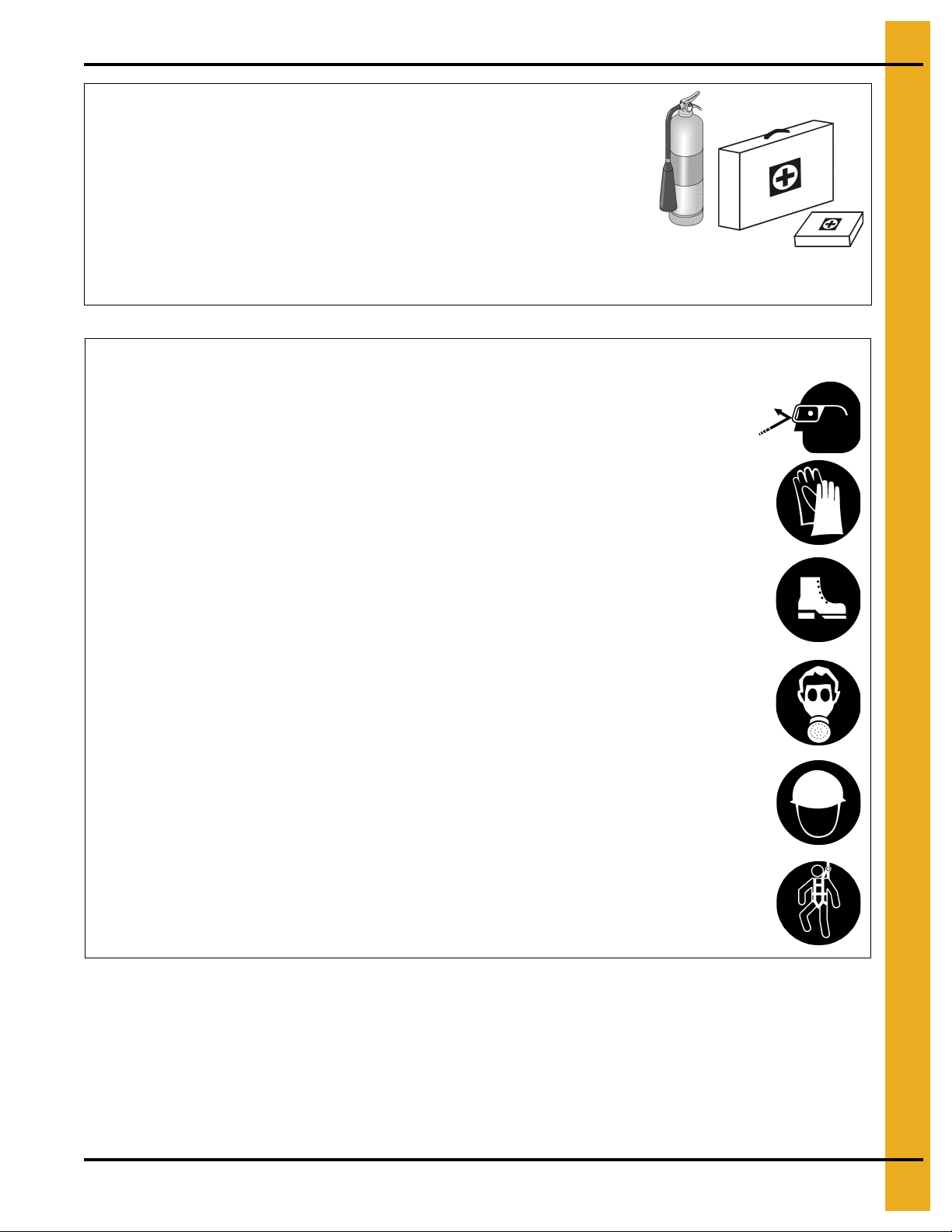
Prepare for Emergencies
Be prepared if fire starts.
Keep a first aid kit and fire extinguisher handy.
Keep emergency numbers for doctors, ambulance service,
hospital, and fire department near your telephone.
Keep Emergency Equipment
Quickly Accessible
Wear Protective Clothing
Wear close-fitting clothing and safety equipment appropriate
to the job.
Remove all jewelry.
Tie long hair up and back.
Wear safety glasses at all times to protect eyes from debris.
Wear gloves to protect your hands from sharp edges on
plastic or steel parts.
Wear steel toed-boots to help protect your feet from falling
debris. Tuck in any loose or dangling shoestrings.
A respirator may be needed to prevent breathing potentially
toxic fumes and dust.
Wear a hard hat to help protect your head.
Wear appropriate fall protection equipment when working at
elevations greater than six feet (6').
Eye Protection
Gloves
Steel-Toed Boots
Respirator
Hard Hat
Fall Protection
PNEG-1460 6', 7' and 9' Bulk Feed Tank BFT Series and GHT Series 9
Page 10

2. Safety
Safety Sign-Off Sheet
As a requirement of O.S.H.A., it is necessary for the employer to train the employee in the safe operating
and safety procedures for this equipment. This sign-off sheet is provided for your convenience and
personal record keeping. All unqualified persons are to stay out of the work area at all times. It is strongly
recommended that another qualified person who knows the shut down procedure be in the area in the
event of an emergency.
Date Employee Name Supervisor Name
10 PNEG-1460 6', 7' and 9' Bulk Feed Tank BFT Series and GHT Series
Page 11

2. Safety
Proper Storage of Grain Bin/Silo Materials Prior to Construction
Wet storage stain (rust) will develop when closely packed bundles of galvanized material, such as sidewall
and roof sheets, have moisture present. Inspect roof and sidewall bundles on arrival for any moisture. If
moisture is present, it must not be allowed to remain between the sheets. Separate the sheets or panels
immediately and wipe them down. Spray with a light oil or diesel fuel.
If possible, sidewall bundles, roof sheets and other closely packed galvanized materials should be stored
in a dry, climate controlled building. If outdoor storage is unavoidable, the materials should be stored so
that they are raised above the ground and vegetation. Any stacking and spacing materials should not be
corrosive or wet. Be sure to protect materials from the weather, but permit air movement around the
bundles if possible.
Storing roof bundles and sidewall sheets at a slight incline can also help minimize the presence of
moisture. Storing the bundles with the center of the dome up (like an arch) is one option for minimizing
moisture during storage. Sidewall bundles can also be stored on edge but must be secured so that they
do not fall over and cause injury.
If “white rust” or “wet storage stain” occurs, contact the manufacturer immediately about ways to minimize
the adverse effect upon the galvanized coating.
PNEG-1460 6', 7' and 9' Bulk Feed Tank BFT Series and GHT Series 11
Page 12
3. Decals
GSI Decals
1004 E. Illinois St.
Assumption, IL. 62510
Phone: 1-217-226-4421
For replacement decals, contact:
DC-2307GSI Group, 217-226-4421
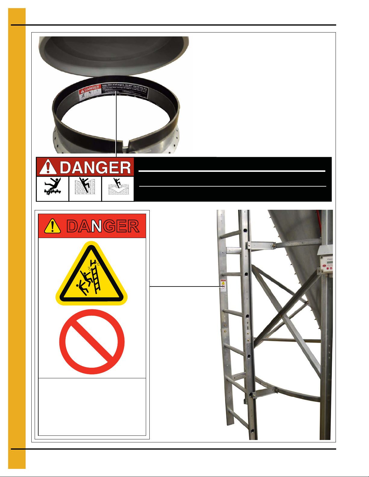
DANGER
DO NOT EXCEED LADDER
LOAD LIMIT
Load limit = 300 LBS (136 kg)
Excessive load will damage
ladder resulting in injury or death.
> 300 lbs
(136 kg)
Rotating flighting will
kill or dismember.
Flowing material will
trap and suffocate.
Crusted material will
collapse and suffocate.
Keep clear of all augers. DO NOT ENTER this bin!
Failure to heed these warnings will result in serious injury or death.
If you must enter the bin:
1. Shut off and lock out all power.
2. Use a safety harness and safety line.
3. Station another person outside the bin.
4. Avoid the center of the bin.
5. Wear proper breathing equipment or respirator.
DC-2123
12 PNEG-1460 6', 7' and 9' Bulk Feed Tank BFT Series and GHT Series
Page 13

4. General Information
Bulk Feed Tank Assembly Manual General Instructions
This product is intended for the use of storing feed only. Any other use is a misuse of the product.
While every effort has been made to keep the edges from being sharp, please wear the proper protective
clothing while erecting the Bulk Feed Tank.
Our company recommends that you contact the local power company and have a representative review
the installation so the wiring will be compatible with their system and so that you will have adequate power
supplied to the unit.
A Bulk Feed Tank weighs a minimum of 444 lbs. (201kg). All precautions should be taken when raising
the tank to its feet. Follow the instructions given later in this manual.
The safety pages show you where you can find the safety decals. The photographs show exactly
where the decals should be. If a decal has been damaged or is missing contact our company for a
free replacement.
First, read the assembly manual completely before starting to assemble your Bulk Feed Tank. Check the
shipment with the packing list to be sure there are no shortages.
1. Decal protective mask must be removed when assembling tank. Mask may become difficult to
remove if left exposed to sunlight.
2. Vertical seams must be staggered on all sidewall rings.
3. When legs extend up 2 rings, the leg holes must be in alignment in the bottom 2 rings.
4. All hopper seams and the hopper collar use truss head bolts. The heads of the bolts must be on the
inside of the tank.
5. Hex head bin bolts are used on all sidewall and roof seams with the bolt heads on the outside of
the bin.
6. Hex head bolts are to be used on all leg to sidewall connections with the bolt heads on the inside of
the tank.
7. All bolts are to be tightened from the nut side only. Do not allow bolt heads to spin.
8. 7' Diameter sidewall sheets must be bolted together so there is 65-5/8" between leg holes.
(See Page 88.)
9. Drift punches can be used to align holes.
10. All vertical sidewall sheet seams must be overlapped in the same direction.
11. A hole spacing of 3-1/8" is used at the top of all top sidewall sheets and at the bottom of all bottom
sidewall sheets.
Selecting the Proper Site
The selected site should be level, firm and free from underlying debris. The tank can be installed
satisfactorily on slopes, but as the slope increases, additional labor and materials are required for the
foundation. The concrete foundation surfaces must be level
and tamped thoroughly to prevent uneven settling from the weight of the tank. Good water dra inage should
be provided to prevent water collecting under or aro und the tank. The site must allow convenient access
for loading and unloading and provide additional space for future units. Also, consider the positioning of
handling equipment, availability of electricity, etc.
PNEG-1460 6', 7' and 9' Bulk Feed Tank BFT Series and GHT Series 13
. If some fill is required, it should be watered
Page 14

4. General Information
Tools
Tools recommended for assembly of Bulk Feed Tanks.
1. Assorted sizes of combination wrenches
2. Hammer
3. 3-12" Long drift punches
4. 1 Large flathead screwdriver
5. 1 Pair of slip joint pliers
6. Two (2) adjustable wrenches
7. Ratchet and sockets
8. Impact wrenches and sockets (if available)
14 PNEG-1460 6', 7' and 9' Bulk Feed Tank BFT Series and GHT Series
Page 15
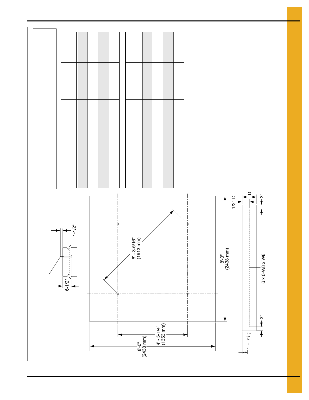
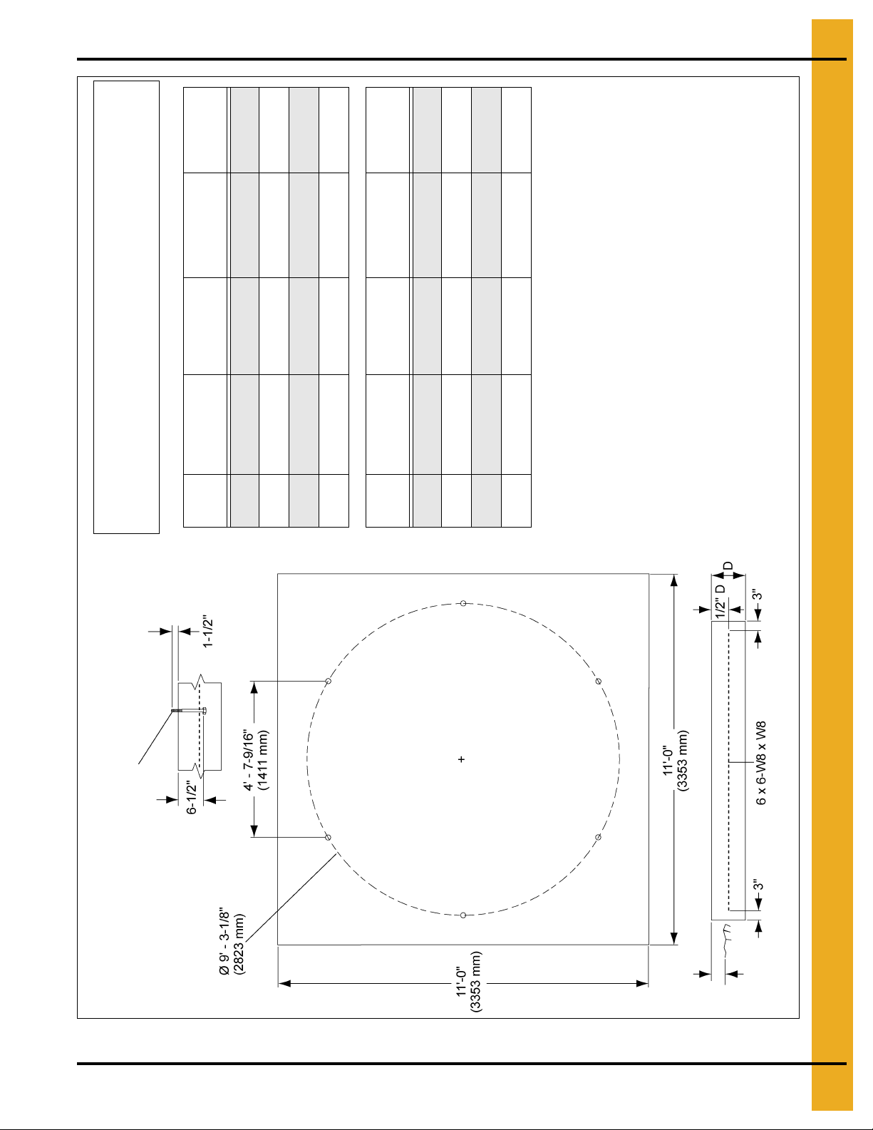
5. Foundation
# of
Rings
Slab
Thickness (D)
Concrete
Volume
Wire Mesh
Area
# of Column
Legs
1-5 11" 2.2 Cu. Yards 60 Sq. Ft. 4
6 13" 2.6 Cu. Yards 60 Sq. Ft. 4
7 15" 3.0 Cu. Yards 60 Sq. Ft. 4
8 18" 3.6 Cu. Yards 60 Sq. Ft. 4
# of
Rings
Slab
Thickness (D)
Concrete
Volume
Wire Mesh
Area
# of Column
Legs
1-5 279 mm 1.68 Cu. Meters 5.57 Sq. Meters 4
6 330 mm 1.99 Cu. Meters 5.57 Sq. Meters 4
7 381 mm 2.29 Cu. Meters 5.57 Sq. Meters 4
8 457 mm 2.75 Cu. Meters 5.57 Sq. Meters 4
All instructions shall be construed as recommendations only. The actual
installation may vary according to local conditions. The GSI Group assumes
no liability for results arising from the use of such recommendations.
GENERAL NOTES:
1. Foundation recommendations are based on 3500 lbs./ft.^2 allowable
soil bearing capacity.
2. Foundation recommendations are based on a minimum compressive
strength of 3000 PSI at 28 days.
3. The foundation site must be well drained and free of vegetation
and debris.
4. The foundation should be level within 1/4" overall and within
± 1/8" in any 10' length along the anchor bolt circle.
5. Material estimates do not include allowance for shrinkage and waste.
6. These layouts are recommendations for GSI tanks only. Consult GSI
engineering for special tank foundations.
Anchor bolt 5/8" x 8" (203 mm) bolt with a
1/8" thick x 1-3/4" O.D. washer on head.
6" Maximum
Grade
Figure 5A 6' 1-8 Rings Square Pad
PNEG-1460 6', 7' and 9' Bulk Feed Tank BFT Series and GHT Series 15
Page 16
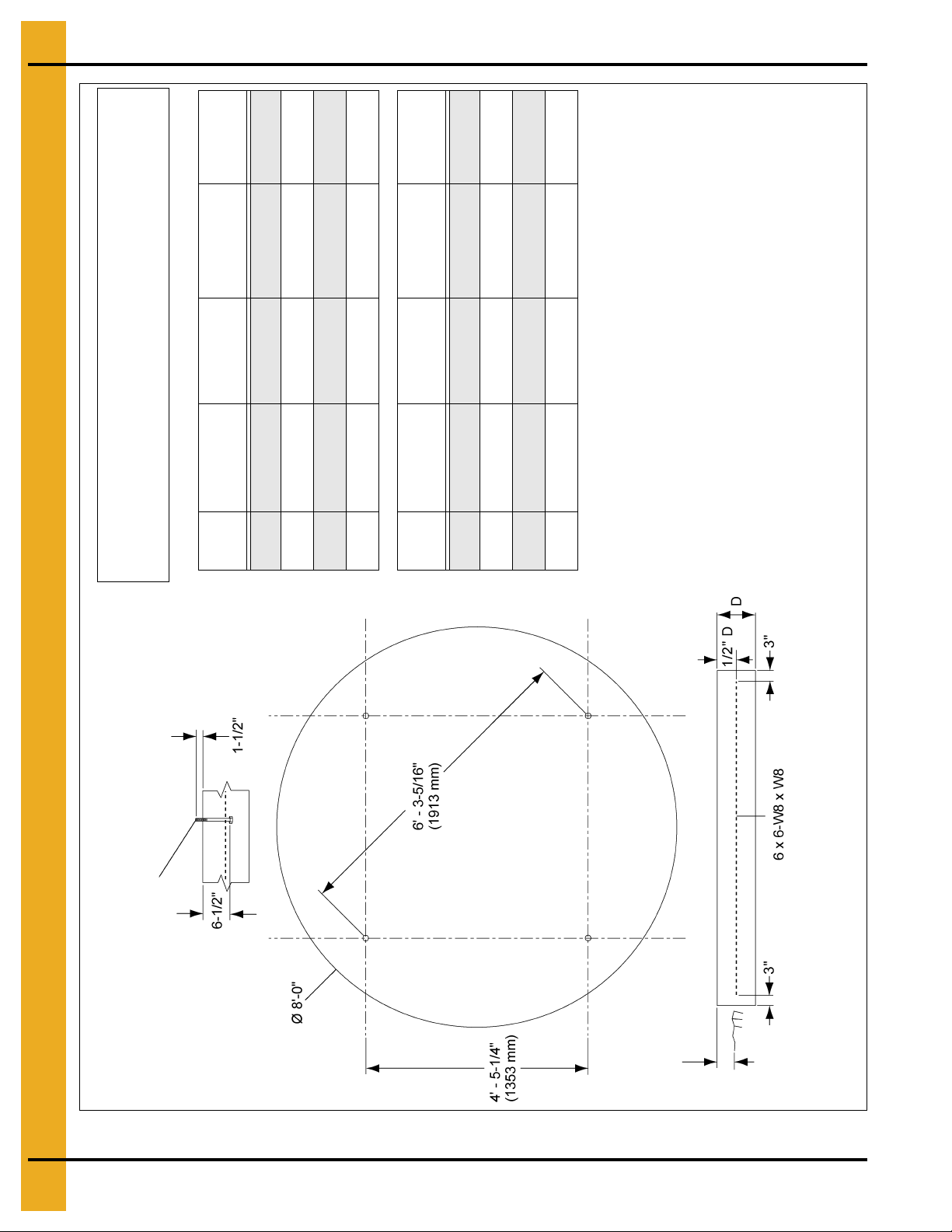
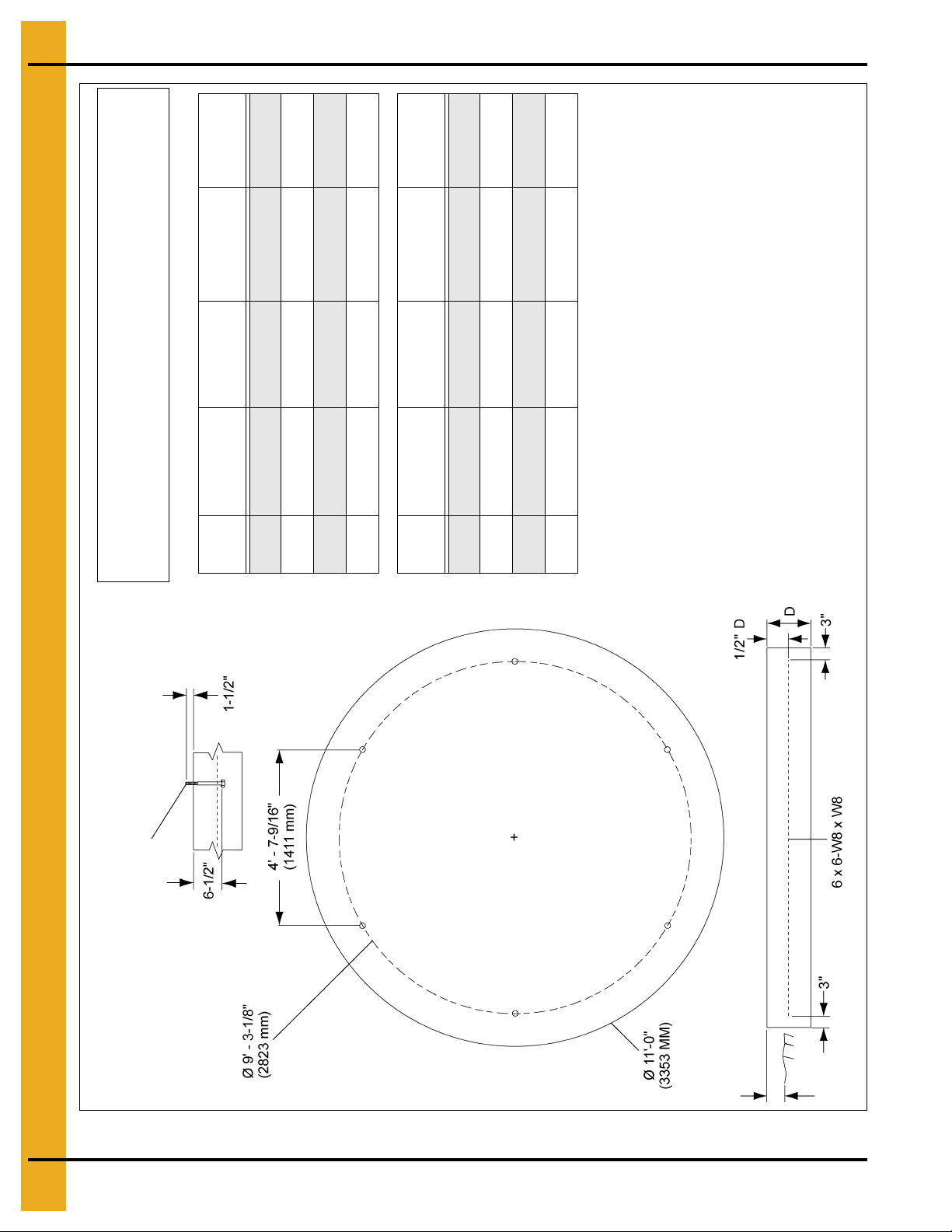
5. Foundation
# of
Rings
Slab
Thickness (D)
Concrete
Volume
Wire Mesh
Area
# of Column
Legs
1-5 11" 1.7 Cu. Yards 55 Sq. Ft. 4
6 13" 2.0 Cu. Yards 55 Sq. Ft. 4
7 15" 2.4 Cu. Yards 55 Sq. Ft. 4
8 18" 2.8 Cu. Yards 55 Sq. Ft. 4
# of
Rings
Slab
Thickness (D)
Concrete
Volume
Wire Mesh
Area
# of Column
Legs
1-5 279 mm 1.31 Cu. Meters 5.11 Sq. Meters 4
6 330 mm 1.54 Cu. Meters 5.11 Sq. Meters 4
7 381 mm 1.78 Cu. Meters 5.11 Sq. Meters 4
8 457 mm 2.13 Cu. Meters 5.11 Sq. Meters 4
All instructions shall be construed as recommendations only. The actual
installation may vary according to local conditions. The GSI Group assumes
no liability for results arising from the use of such recommendations.
GENERAL NOTES:
1. Foundation recommendations are based on 3500 lbs./ft.^2 allowable
soil bearing capacity.
2. Foundation recommendations are based on a minimum compressive
strength of 3000 PSI at 28 days.
3. The foundation site must be well drained and free of vegetation
and debris.
4. The foundation should be level within 1/4" overall and within
± 1/8" in any 10' length along the anchor bolt circle.
5. Material estimates do not include allowance for shrinkage and waste.
6. These layouts are recommendations for GSI tanks only. Consult GSI
engineering for special tank foundations.
Anchor bolt 5/8" x 8" (203 mm) bolt with a
1/8" thick x 1-3/4" O.D. washer on head.
6" Maximum
Grade
Figure 5B 6' 1-8 Rings BFT/ GHT Round Pad
16 PNEG-1460 6', 7' and 9' Bulk Feed Tank BFT Series and GHT Series
Page 17
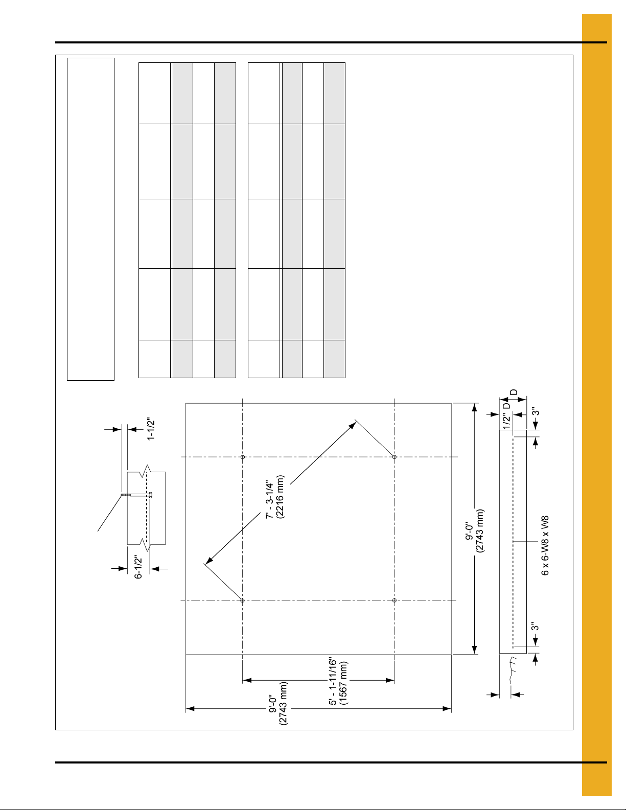
5. Foundation
# of
Rings
Slab
Thickness (D)
Concrete
Volume
Wire Mesh
Area
# of Column
Legs
1-6 13" 3.3 Cu. Yards 80 Sq. Ft. 4
7 14" 3.5 Cu. Yards 80 Sq. Ft. 4
8 17" 4.3 Cu. Yards 80 Sq. Ft. 4
# of
Rings
Slab
Thickness (D)
Concrete
Volume
Wire Mesh
Area
# of Column
Legs
1-6 330 mm 2.52 Cu. Meters 7.43 Sq. Meters 4
7 356 mm 2.68 Cu. Meters 7.43 Sq. Meters 4
8 432 mm 3.29 Cu. Meters 7.43 Sq. Meters 4
All instructions shall be construed as recommendations only. The actual
installation may vary according to local conditions. The GSI Group assumes
no liability for results arising from the use of such recommendations.
GENERAL NOTES:
1. Foundation recommendations are based on 3500 lbs./ft.^2 allowable
soil bearing capacity.
2. Foundation recommendations are based on a minimum compressive
strength of 3000 PSI at 28 days.
3. The foundation site must be well drained and free of vegetation
and debris.
4. The foundation should be level within 1/4" overall and within
± 1/8" in any 10' length along the anchor bolt circle.
5. Material estimates do not include allowance for shrinkage and waste.
6. These layouts are recommendations for GSI tanks only. Consult GSI
engineering for special tank foundations.
Anchor bolt 5/8" x 8" (203 mm) bolt with a
1/8" thick x 1-3/4" O.D. washer on head.
6" Maximum
Grade
Figure 5C 7' 1-8 Rings BFT/ GHT 45° and 67° Square Pad
PNEG-1460 6', 7' and 9' Bulk Feed Tank BFT Series and GHT Series 17
Page 18
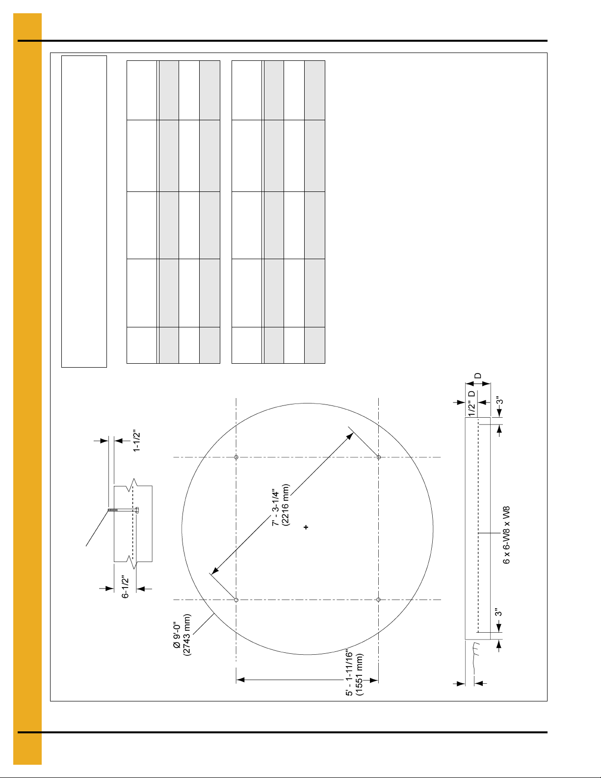
5. Foundation
# of
Rings
Slab
Thickness (D)
Concrete
Volume
Wire Mesh
Area
# of Column
Legs
1-6 13" 2.6 Cu. Yards 65 Sq. Ft. 4
7 14" 2.8 Cu. Yards 65 Sq. Ft. 4
8 17" 3.4 Cu. Yards 65 Sq. Ft. 4
# of
Rings
Slab
Thickness (D)
Concrete
Volume
Wire Mesh
Area
# of Column
Legs
1-6 330 mm 1.91 Cu. Meters 6.04 Sq. Meters 4
7 356 mm 2.10 Cu. Meters 6.04 Sq. Meters 4
8 432 mm 2.55 Cu. Meters 6.04 Sq. Meters 4
All instructions shall be construed as recommendations only. The actual
installation may vary according to local conditions. The GSI Group assumes
no liability for results arising from the use of such recommendations.
GENERAL NOTES:
1. Foundation recommendations are based on 3500 lbs./ft.^2 allowable
soil bearing capacity.
2. Foundation recommendations are based on a minimum compressive
strength of 3000 PSI at 28 days.
3. The foundation site must be well drained and free of vegetation
and debris.
4. The foundation should be level within 1/4" overall and within
± 1/8" in any 10' length along the anchor bolt circle.
5. Material estimates do not include allowance for shrinkage and waste.
6. These layouts are recommendations for GSI tanks only. Consult GSI
engineering for special tank foundations.
Anchor bolt 5/8" x 8" (203 mm) bolt with a
1/8" thick x 1-3/4" O.D. washer on head.
6" Maximum
Grade
18 PNEG-1460 6', 7' and 9' Bulk Feed Tank BFT Series and GHT Series
Figure 5D 7' 1-8 Rings BFT/ GHT 45° and 67° Round Pad
Page 19
5. Foundation
# of
Rings
Slab
Thickness (D)
Concrete
Volume
Wire Mesh
Area
# of Column
Legs
2-6 13" 4.9 Cu. Yards 125 Sq. Ft. 6
7 16" 6.0 Cu. Yards 125 Sq. Ft. 6
8 17" 6.4 Cu. Yards 125 Sq. Ft. 6
9 17" 6.4 Cu. Yards 125 Sq. Ft. 6
# of
Rings
Slab
Thickness (D)
Concrete
Volume
Wire Mesh
Area
# of Column
Legs
2-6 330 mm 4.85 Cu. Meters 11.61 Sq. Meters 6
7 406 mm 4.85 Cu. Meters 11.61 Sq. Meters 6
8 432 mm 5.14 Cu. Meters 11.61 Sq. Meters 6
9 432 mm 5.14 Cu. Meters 11.61 Sq. Meters 6
All instructions shall be construed as recommendations only. The actual
installation may vary according to local conditions. The GSI Group assumes
no liability for results arising from the use of such recommendations.
GENERAL NOTES:
1. Foundation recommendations are based on 3500 lbs./ft.^2 allowable
soil bearing capacity.
2. Foundation recommendations are based on a minimum compressive
strength of 3000 PSI at 28 days.
3. The foundation site must be well drained and free of vegetation
and debris.
4. The foundation should be level within 1/4" overall and within
± 1/8" in any 10' length along the anchor bolt circle.
5. Material estimates do not include allowance for shrinkage and waste.
6. These layouts are recommendations for GSI tanks only. Consult GSI
engineering for special tank foundations.
* Applies to 45° hopper Tank only.
*
*
Anchor bolt 5/8" x 8" (203 mm) bolt with a
1/8" thick x 1-3/4" O.D. washer on head.
6" Maximum
Grade
6 Legs
PNEG-1460 6', 7' and 9' Bulk Feed Tank BFT Series and GHT Series 19
Figure 5E 9' 2-9 Rings BFT/ GHT 45° and 60° Square Pad
Page 20
5. Foundation
# of
Rings
Slab
Thickness (D)
Concrete
Volume
Wire Mesh
Area
# of Column
Legs
2-6 13" 3.8 Cu. Yards 100 Sq. Ft. 6
7 16" 4.7 Cu. Yards 100 Sq. Ft. 6
8 17" 5.0 Cu. Yards 100 Sq. Ft. 6
9 17" 5.0 Cu. Yards 100 Sq. Ft. 6
# of
Rings
Slab
Thickness (D)
Concrete
Volume
Wire Mesh
Area
# of Column
Legs
2-6 330 mm 2.91 Cu. Meters 9.29 Sq. Meters 6
7 406 mm 3.59 Cu. Meters 9.29 Sq. Meters 6
8 432 mm 3.82 Cu. Meters 9.29 Sq. Meters 6
9 432 mm 3.82 Cu. Meters 9.29 Sq. Meters 6
All instructions shall be construed as recommendations only. The actual
installation may vary according to local conditions. The GSI Group assumes
no liability for results arising from the use of such recommendations.
GENERAL NOTES:
1. Foundation recommendations are based on 3500 lbs./ft.^2 allowable
soil bearing capacity.
2. Foundation recommendations are based on a minimum compressive
strength of 3000 PSI at 28 days.
3. The foundation site must be well drained and free of vegetation
and debris.
4. The foundation should be level within 1/4" overall and within
± 1/8" in any 10' length along the anchor bolt circle.
5. Material estimates do not include allowance for shrinkage and waste.
6. These layouts are recommendations for GSI tanks only. Consult GSI
engineering for special tank foundations.
* Applies to 45° hopper tank only.
*
*
Anchor bolt 5/8" x 8" (203 mm) bolt with a
1/8" thick x 1-3/4" O.D. washer on head.
6" Maximum
Grade
6 Legs
20 PNEG-1460 6', 7' and 9' Bulk Feed Tank BFT Series and GHT Series
Figure 5F 9' 2-9 Rings BFT/ GHT 45° and 60° Round Pad
Page 21
Tank Sidewalls
6. Sidewall Assembly
Sidewall Sheet Gauge Chart
Model Gauge
BFT 6'-1 Ring 20
BFT 6'-2 Ring 20-20
BFT 6'-3 Ring 18-20-20
BFT 6'-4 Ring 18-20-20-20
BFT 7'-1 Ring 20
BFT 7'-2 Ring 18-20
BFT 7'-3 Ring 18-20-20
BFT 7'-4 Ring 18-18-20-20
BFT 7'-5 Ring 17-17-18-20-20
BFT 7'-6 Ring 15-15-17-18-20-20
BFT 9'-1 Ring 20
BFT 9'-2 Ring 20-20
BFT 9'-3 Ring 20-20-20
BFT 9'-4 Ring 18-18-20-20
BFT 9'-5 Ring 17-17-18-20-20
BFT 9'-6 Ring 15-15-17-18-20-20
How to use charts on this page:
The chart labeled “Sidewall Sheet Gauge Chart” is for the reference when building the tank. This chart tells
you what gauges your rings of the specific tank must have. To read the chart find the tank size you are
build. For example, a 7' diameter tank with 4 rings is referred to as BFT 7'-4 ring. The side lab eled “Gauge”
will indicate which sidewall sheets to use. The sheets are color coded, simply match the gauge number
with the color. (Use “Sheet Gauge Color Code Chart” below.)
NOTE: Sidewall sheets are color coded on edges for gauge identification.
Sheet Gauge Color Code Chart
Code # Color Code
20 Red
18 Orange
17 Pink/Light Blue
16 Blue
15 Brown/Red
14 Green
13 Yellow/Blue
12 Black
11 Pink
10 Light Blue
PNEG-1460 6', 7' and 9' Bulk Feed Tank BFT Series and GHT Series 21
Page 22
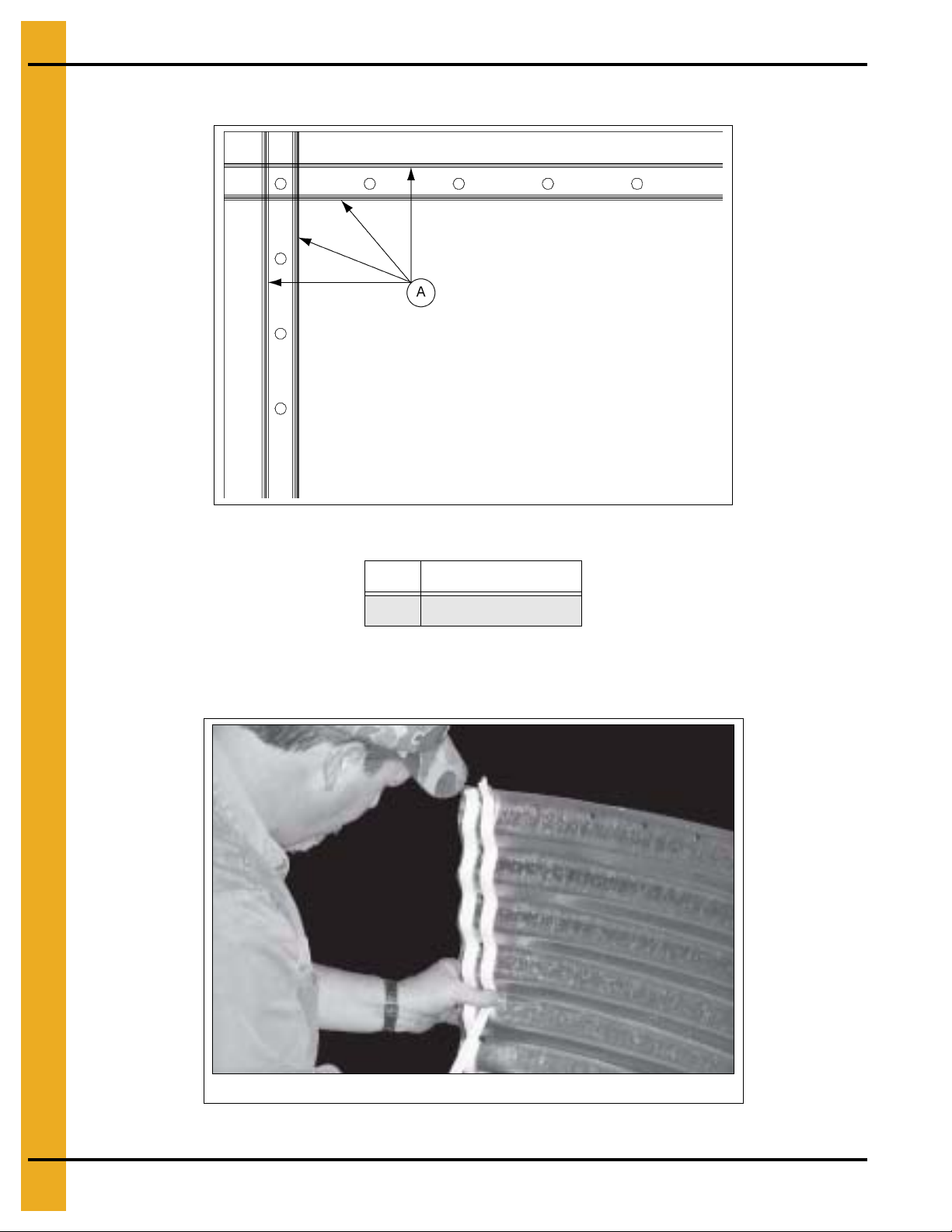
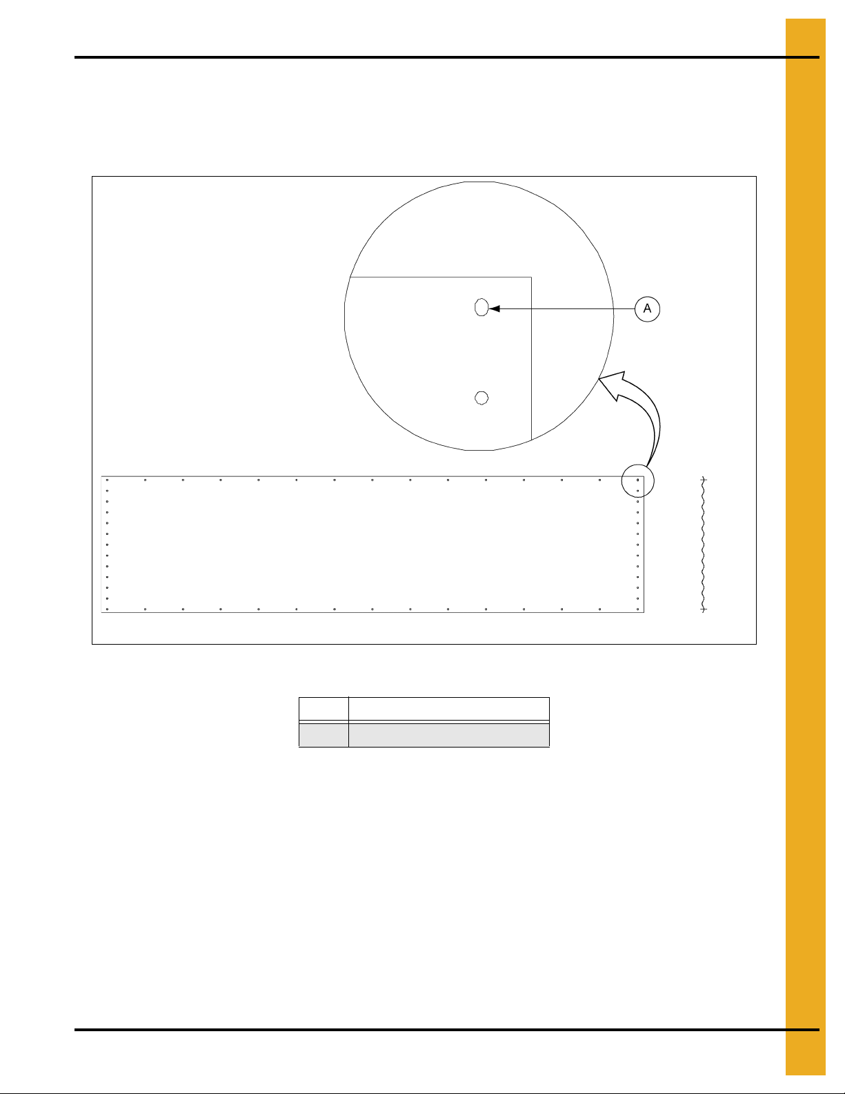
6. Sidewall Assembly
Caulking is applied to all BFT parts before assembly.
Caulking Detail
Figure 6A Caulking Detail
Ref # Description
A Caulking
NOTE: Rope caulking is applied before each sheet is assembled. Wipe sheet clean where it will be
applied. Apply caulking on each side of the holes of the vertical seams and on each side of the
horizontal row of holes.
Figure 6B
22 PNEG-1460 6', 7' and 9' Bulk Feed Tank BFT Series and GHT Series
Page 23
6. Sidewall Assembly
Slot detail
End view
Sidewall Sheet Orientation
IMPORTANT: Ple ase note sheet orientation when assembling the bin sidewall. The upper right corner will
have a slot or identifying sticker. This corner should be on the inside of the tank when
assembled. (See Figure 6C.)
Figure 6C Viewed from Inside (Sheet orientation effects how sheet overlap.)
Ref # Description
A 3/8" x 1/2" Slot (One per Sheet)
Sidewall Assembly
Start by assembling the top ring of the Bulk Feed Tank. The top row of bolt holes has 3-1/8" spacing in
the top ring. Before bolting the sidewall sheets together, check that you have the proper gauge steel for
the top ring. The higher gauge number denotes thinner materia l. For example, 20 gauge material is thinner
than 14 gauge. In assembling all Bulk Feed Tanks the thinnest material always go on top. The heaviest
corrugated sidewall sheets will be located on the bottom of the tank. Check the various gauges of the
tank with the “Sheet Gauge Color Code Chart” and “Sidewall Sheet Gauge Chart”, on Page 21. Begin
by putting the rings together on the edge of the sheets. On 7'-1 ring tanks ensure vertical leg seams
are spaced equally around tank. (See Page 88.) After the first ring is complete, the roof must be assembled
as described on Pages 24-25. After the roof is assembled, the tank can be rolled on its side for easier
sidewall assembly. (See Figure 6F on Page 25.)
Tighten all bolts from the nut side only.
PNEG-1460 6', 7' and 9' Bulk Feed Tank BFT Series and GHT Series 23
Page 24
6. Sidewall Assembly
Inside of tank
First ring assembly. Tighten
bolts from the nut side only.
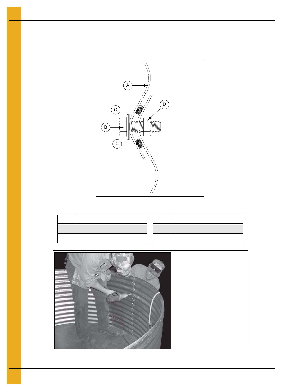
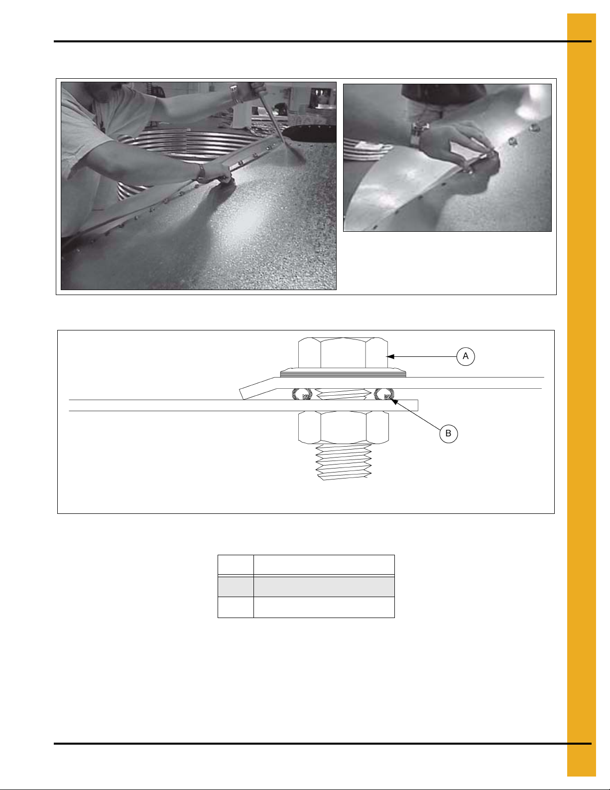
Continue to add rings with lighter gauges first, then heavier gauges. Each subsequent row of sidewall
sheets goes to the inside of the previous row of sidewall panels. Remember to place the caulking between
every ring. See Figure 6D for illustration of proper sidewall overlap and caulking detail.
Be sure to stagger all vertical seams between rows.
Figure 6D Ring Overlap Detail
Ref # Description Ref # Description
A Upper Ring C Caulking Two (2) Strips
B 5/16" x 1" Bolt
D 5/16" Nut
Figure 6E
24 PNEG-1460 6', 7' and 9' Bulk Feed Tank BFT Series and GHT Series
Page 25
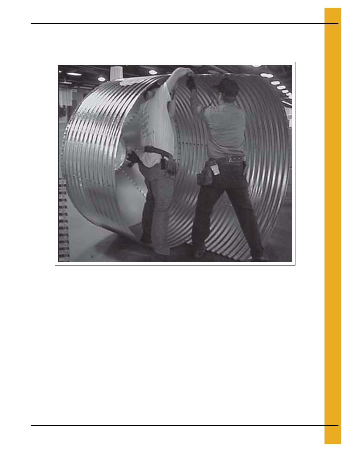
6. Sidewall Assembly
IMPORTANT: Begin bolting in the center of sheets when connecting sidewall rings to one another.
When bolting sidewall rings to one another, always begin bolting in the center of the sh eet and work toward
the outside edges (horizontal seams). This allows the sidewall to draw up evenly.
Figure 6F Sidewall Assembly
It is easier to add more sidewall sheets with the tank on its side. It can be rolled easily from side-to-side
to allow the bolts and nuts to be put in the proper holes. NOTE: The roof must be assembled on the first
ring before rolling it over to its side.
PNEG-1460 6', 7' and 9' Bulk Feed Tank BFT Series and GHT Series 25
Page 26
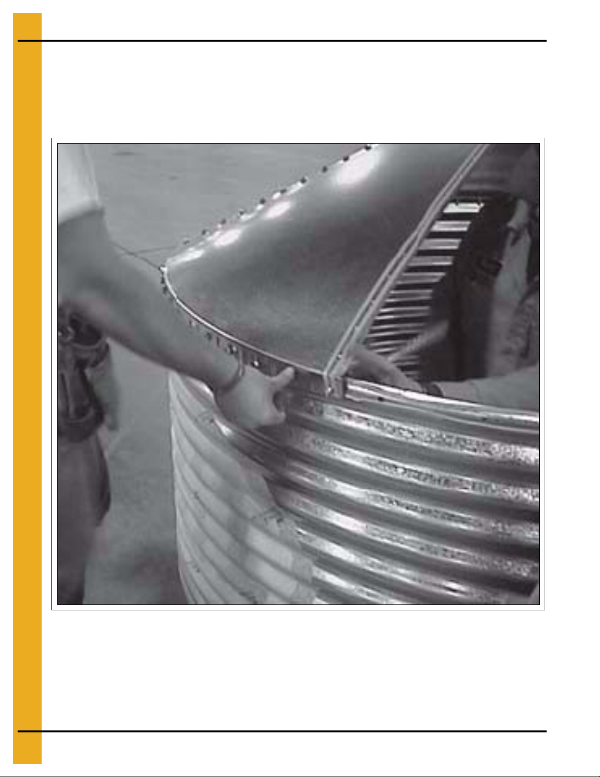
7. Roof
Sealed Roof Panels Installation
NOTE: The roof and sidewall ladders are centered between seams. When placing the roof panel, the
outside edge is bent down. This edge is to be placed on the outside of other roof panel to form a tight seal.
(See Figure 7C on Page 27.) Be sure to apply two (2) strips of caulking on all seams. Assemble roof panels
in a counterclockwise manner.
Figure 7A
On bins that will be equipped with a pneumatic fill system (See Page 81), the two (2) roof panels with fill
hole and exhaust hole must be located opposite each other on the Bulk Feed Tank.
26 PNEG-1460 6', 7' and 9' Bulk Feed Tank BFT Series and GHT Series
Page 27
Sealed Roof Panels Installation (Continued)
Inside of tank
Figure 7B Lining Up Holes and Placing Bolts
7. Roof
PNEG-1460 6', 7' and 9' Bulk Feed Tank BFT Series and GHT Series 27
Figure 7C Roof Sheet Overlap Detail
Ref # Description
A 5/16" x 1" Bin Bolt
B Caulking Two (2) Strips
Page 28
7. Roof
A
D
D
D
C
Inside of tank
Peak Ring Collar to Roof Panels
Apply two (2) strips of caulking between peak ring and roof panels, Se e Figure 7D. Note that the peak ring
goes on the outside of the roof panels.
Figure 7E
Ref # Description
A Peak Ring Collar
Figure 7D
B Roof Sheet
C 5/16" x 1" Bin Bolt
D Caulking Two (2) St rips
28 PNEG-1460 6', 7' and 9' Bulk Feed Tank BFT Series and GHT Series
Figure 7F Peak Ring Collar Detail
Page 29
8. Optional BFT Ladder Assembly
See Page 30 for proper
orientation of bracket.
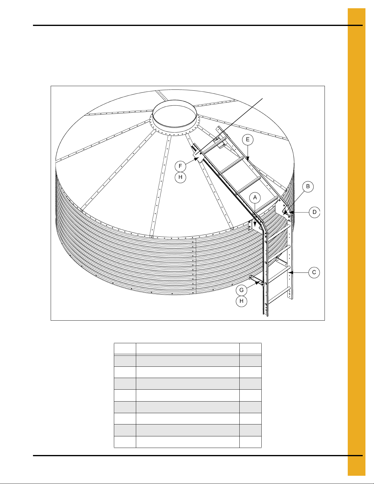
Optional BFT Ladder Assembly
The components needed to complete the eave ladder assembly are listed in the chart below and are
numbered in the order of assembly. Review the installation instructions for each component before
beginning. Failure to do so may complicate the installation and cause unnecessary field drilling.
(See Figure 8A.)
PNEG-1460 6', 7' and 9' Bulk Feed Tank BFT Series and GHT Series 29
Figure 8A
Ref # Description Qty
A L.H. Starter Bracket 1
B R.H. Starter Bracket 1
C Top 4' Ladder Section 1
D Connector Bracket 2
E Roof Ladder Section 1
F Roof Ladder Support Bracket 2
G Standoff Bracket 2
H Wedge 4
Page 30
8. Optional BFT Ladder Assembly
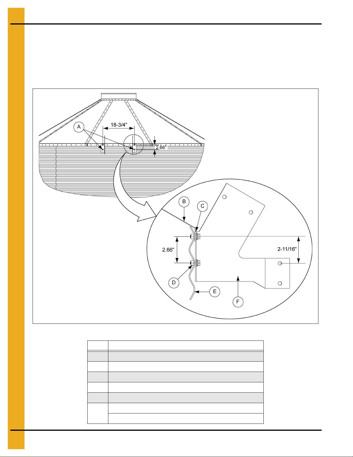
Starter Bracket Installation
The starter brackets must be centered in the roof sheet to ensure proper installation of the roof ladder
support brackets. Before the starter brackets can be installed, two (2) 3/8" holes must be drilled. The
holes must be 2.66" below and directly in line with the top row of pre-punched horizontal holes 18-3/4"
apart. Refer to Figure 8B for additional clarification of hole locations. Use 5/16" and 1" bin bolts
for connections.
Figure 8B
Ref # Description
A Two (2) 3/8" Field Drilled Holes
B Roof Panel
C Top Horizontal Seam
D 3/8" Field Drilled Holes
E Sidewall Sheet
L.H. 30° Roof (LDR-5405) and R.H. 30° Roof (LDR-5406)
F
L.H. 40° Roof (LDR-5407) and R.H. 40° Roof (LDR-5408)
30 PNEG-1460 6', 7' and 9' Bulk Feed Tank BFT Series and GHT Series
Page 31

8. Optional BFT Ladder Assembly
Failure to follow instructions may cause damage or failure of the equipment.
WARNING
Sidewall and Roof Ladder Installation
Check the sidewall ladder to make sure the ladder rung dimples face upward. Attach the ladder to the
sidewall with the starter brackets to the inside of the ladder and the connector brackets to the outside as
shown in Figure 8C. Once the sidewall ladder is installed, attach the roof ladder to the other end of the
connector brackets. All bolts should be installed with the head of the bolt to the inside of the ladder.
Use 5/16" x 1" bin bolts for all connections.
NOTE: The roof ladder must be one continuous ladder section. The roo f ladder cannot
two (2) or more smaller ladder sections spliced together. See chart below for required roof ladder
lengths vs bin diameter and roof angle.
Roof Ladder Length
Bin Diameter
30° Roof 40° Roof
6' 3' 3'
7' 3' 3'
9' 4' 5'
be assembled from
Figure 8C
Ref # Part # Description
LDR-4318 30° Connector Bracket D S-10260 5/16" x 1" Bin Bolt
A
LDR-4367 40° Connector Bracket E Sidewall Ladder
B S-845 5/16" Flat Washer F Roof Ladder
C S-7484 5/16" Nut
PNEG-1460 6', 7' and 9' Bulk Feed Tank BFT Series and GHT Series 31
Ref # Part # Description
Page 32

8. Optional BFT Ladder Assembly
Failure to follow instructions may cause damage or failure of the equipment.
Slide
Roof Ladder Support Bracket Installation
The roof ladder requires support brackets at the top of the ladder. These upper ladder support brackets
either bend in towards the center o f the ladder or bend out away from the ladder depending on the diameter
and roof angle of the tank being assembled.
brackets for the 6' 30°, 9' 30° and 9'-40° roofs.
that show brackets for 6' 40°, 7' 30° and 7' 40° roofs. Assemble the wedge and support brackets to the
ladder rail as shown in
along the ladder rails as shown in
Figure 8F and Figure 8G on Page 34
Figure 8D below and Figure 8E on Page 33
the pre-punched holes in the roof panel and attach using the existing bolts.
NOTE: The roof ladder supports must be assembled so that the maximum distances are not exceeded.
See Figure 8J on Page 36 and the “maximum distances chart” to determine maximum allowable
spacing of support brackets.
WARNING
See Figure 8D below and Figure 8H on Page 35
that show
See Figure 8E on Page 33 and Figure 8I on Page 35
. Then, slide the support bracket assemblies
until the slots match up with
Figure 8D
Ref # Part # Description
LDR-5403 30° Support Bracket
A
32 PNEG-1460 6', 7' and 9' Bulk Feed Tank BFT Series and GHT Series
LDR-5404 40° Support Bracket
Page 33

8. Optional BFT Ladder Assembly
Slide
Roof Ladder Support Bracket Installation (Continued)
Figure 8E
Ref # Part # Description
LDR-4386 30° Support Bracket
A
LDR-4387 40° Support Bracket
PNEG-1460 6', 7' and 9' Bulk Feed Tank BFT Series and GHT Series 33
Page 34

8. Optional BFT Ladder Assembly
Roof Ladder Support Bracket Installation (Continued)
Figure 8F Figure 8G
Ref # P art # Description
A LDR-4198 Wedge
B S-3550 5/16" x 1" Carriage Bolt
LDR-5403 30° Support Bracket
C
LDR-5404 40° Support Bracket
D S-10268 Flange Nut 5/16"-18 JS Grade 5
E Ladder
34 PNEG-1460 6', 7' and 9' Bulk Feed Tank BFT Series and GHT Series
Page 35

8. Optional BFT Ladder Assembly
Top view for these tanks: All 6' diameter 30° sealed roofs.
All 9' diameter 30° sealed roofs.
(Not in scale.)
All 9' diameter 40° sealed roofs.
Top view for these tanks: All 6' diameter 40° sealed roofs.
All 7' diameter 30° sealed roofs.
All 7' diameter 40° sealed roofs.
(Not in scale.)
Roof Ladder Support Bracket Installation (Continued)
Figure 8H Figure 8I
Ref # Part # Description
LDR-5403 30° Support Bracket
A
LDR-5404 40° Support Bracket
PNEG-1460 6', 7' and 9' Bulk Feed Tank BFT Series and GHT Series 35
Ref # Part # Description
LDR-4386 30° Support Bracket
A
LDR-4387 40° Support Bracket
Page 36

8. Optional BFT Ladder Assembly
Roof Ladder Support Bracket Installation (Continued)
Figure 8J Maximum Allowable Distance
Ref # Part # Description
LDR-5403 30° Support Bracket
A
LDR-5404 40° Support Bracket
Maximum Distances Chart “B” “C”
Maximum allowable distance between ladder support
bracket and the edge of the ladder at the eave.
Maximum allowable distance between ladder
support bracket and edge of ladder at peak.
50 Inches
10 Inches
36 PNEG-1460 6', 7' and 9' Bulk Feed Tank BFT Series and GHT Series
Page 37

8. Optional BFT Ladder Assembly
Ladder Standoff Installation
With the sidewall ladder in place, standoff brackets must be installed on the ladder and attached to the
sidewall at each horizontal seam (every 32"). Start by assembling the standoff bracket and wedge t o the
ladder rail as shown in Figure 8K. Then, slide the standoff assembly along the ladder rail until the standoff
is in line with the pre-punched hole in the horizontal seam and attach to the sidewall using 5/16" x 1"
bin bolts.
Figure 8K
Ref # Description
A Roof Ladder
B Connector Bracket
C Starter Bracket
D S idewall Ladder
E Standoff Bracket (Two(2) per Seam) (LDR-4314)
F Horizontal Seam
G 32" Typical
PNEG-1460 6', 7' and 9' Bulk Feed Tank BFT Series and GHT Series 37
Page 38

8. Optional BFT Ladder Assembly
NOTE: Leave bolt loose until cage
hoop half has been attached.
Top view
Ladder Section Assembly
Two (2) splice plates are required to attach each additional ladder section. The head of the bolt should be
to the inside of the ladder with the splice plate on t he outside a s shown in Figure 8L . Use 5/16" x 1" bolts
for all connections.
NOTE: With most installations, the last ladder section to reach the concrete will need to be cut to fit.
Figure 8L
Ref # Part # Description
A LDR-4317 Splice Plate (Two (2) Per Connection)
B LDR-4314 Standoff Bracket
C S-10268 Flange Nut 5/16"-18 JS Grade 5
D S-3550 5/16" x 1" Carriage Bolt
E LDR-4198 Wedge
F Ladder
G Ladder Sections
38 PNEG-1460 6', 7' and 9' Bulk Feed Tank BFT Series and GHT Series
Page 39

8. Optional BFT Ladder Assembly
Ladder Support Detail
The ladder must be secured to the leg assembly with standoff brackets using support channels as shown
in Figure 8M.
Ref # Description
A Support Channel
B Ladder Standoff Bracket (LDR-4314)
C 5/16" x 1" Hardware
Diameter Support Channel Qty
6' BLK-10147 1
7' BLK-10148 2
9' BLK-10149 2
Figure 8M
Ladder Decal Application
Apply the ladder load limit decal (DC-2307) at eye level on the inside of the ladder rail. Make sure the
ladder surface is clean and dry before application. (See Figure 8N.)
DANGER
> 300 lbs
(136 kg)
DO NOT EXCEED LADDER
LOAD LIMIT
Load limit = 300 LBS (136 kg)
Excessive load will damage
ladder resulting in injury or death.
DC-2307GSI Group, 217-226-4421
Figure 8N
PNEG-1460 6', 7' and 9' Bulk Feed Tank BFT Series and GHT Series 39
Page 40

9. Ladder Handrails
Failure to follow instructions may cause damage or failure of the equipment.
WARNING
Handrail Installation for Ladder System Without Safety Cage
Handrail Gusset and Handrail Installation
For ladder systems without safety cages, handrails are required. Begin installation by sliding a handrail bar
assembly through the top rung of the sidewall ladder and another handrail bar assembly through the second
rung of the roof ladder as shown in
must be assembled as shown in
the ladder rungs. The handrail bar assembly pieces will be bolted together when the han drail gussets and
handrails are installed. Position the left hand bottom handrail gusset so that outer most hole lines up with
the outer most hole of the handrail bar assembly. Clamp in place using the wedges, 5/16" x 1" carriage bolt
and 5/16" flange nuts as shown in
assembly as shown. Position the left hand top handrail gusset so that the outer most hole lines up with
the outer most hole of the handrail bar assembly. Clamp in place using the wedges and hardware as
shown in
Figure 9E on Page 44
installation of the handrail tubes. Repeat handrail gusset and wedge installation for the opposite side of the
ladder. Install the handrail tubes using the 5/16" hardware as shown in
wedge hardware when necessary to obtain the proper fit of the handrail tubes. Tighten all hardware to
complete the assembly.
See Figure 9G on Page 46 and Figure 9H on Page 47 for detail.
Figure 9A
Figure 9B on Page 41 and Figure 9C on Page 42
Figure 9D on Page 43
. All four (4) pieces of LDR-5421, LDR-5414 (2) and LDR-5422
and installed through
. Bolt the handrail gusset to the handrail bar
. It will be necessary to loosen the wedge hardware slightly to allow proper
Figure 9F on Page 45
loosening the
Ref # Part # Description Qty
LDR-5421
A
LDR-5414 2
LDR-5422 1
LDR-5421
B
LDR-5414 2
LDR-5422 1
C Roof Ladder
D Sidewall ladder
Handrail Bar Assembly
(See Figure 9B on Page 41.)
Handrail Bar Assembly
(See Figure 9C on Page 42.)
1
1
Figure 9A
40 PNEG-1460 6', 7' and 9' Bulk Feed Tank BFT Series and GHT Series
Page 41

9. Ladder Handrails
Exploded view
Assembled view
Handrail Installation for Ladder System Without Safety
Cage (Continued)
PNEG-1460 6', 7' and 9' Bulk Feed Tank BFT Series and GHT Series 41
Figure 9B
Ref # Part # Description
A LDR-5421 BFT Handrail Support Channel
B LDR-5422 BFT Handrail Support Channel Reinforcement 12 Gauge
C LDR-5414 BFT Handrail Support Channel Reinforcement
Page 42

9. Ladder Handrails
Exploded view
Assembled view
Handrail Installation for Ladder System Without Safety
Cage (Continued)
Figure 9C
Ref # Part # Description
A LDR-5422 BFT Handrail Support Channel Reinforcement 12 Gauge
B LDR-5414 BFT Handrail Support Channel Reinforcement
C LDR-5421 BFT Handrail Support Channel
42 PNEG-1460 6', 7' and 9' Bulk Feed Tank BFT Series and GHT Series
Page 43

9. Ladder Handrails
Handrail Installation for Ladder System Without Safety
Cage (Continued)
Figure 9D
Ref # Part # Description Ref # Part # Description
LDR-5417 Bottom Handrail Gusset L.H. E S-10268 Flange Nut 5/16"-18 JS Grade 5
A
LDR-5418 Bottom Handrail Gusset R.H. F S-3550 5/16" x 1" Carriage Bolt
B S-7484 5/16" Nut G Ladder
C S-4276 5/16" x 1-1/4" Hex Head Bolt H Handrail Bar Assembly
D LDR-4198 Ladder Standoff Wedge
PNEG-1460 6', 7' and 9' Bulk Feed Tank BFT Series and GHT Series 43
Page 44

9. Ladder Handrails
Handrail Installation for Ladder System Without Safety
Cage (Continued)
Figure 9E
Ref # Part # Description Ref # Part # Description
A LDR-4198 Wedge (Two (2) per Side) E S-7484 5/16" Nut (One Per Side)
B S-10268 5/16" Flange Nut (Two (2) per Side)
C S-3550 5/16" x 1" Carriage Bolt (Two (2) per Side) LDR-5416 Top Handrail Gusset R.H.
D S-4276 5/16" x 1-1/4" Hex Head Bolt (One per Side) G Handrail Bar Assembly
44 PNEG-1460 6', 7' and 9' Bulk Feed Tank BFT Series and GHT Series
LDR-5415 Top Handrail Gusset L.H.
F
Page 45

9. Ladder Handrails
Handrail Installation for Ladder System Without Safety
Cage (Continued)
Figure 9F
Ref # Part # Description
A LDR-5416 Top Handrail Gusset R.H.
B S-7076 5/16" x 2-1/2" Hex Head Bolt (4)
C S-7877 5/16" x 2" Hex Head Bolt (8)
LDR-5423 30° Handrail
D
LDR-5424 40° Handrail
E LDR-5418 Bottom Handrail Gusset R.H.
F LDR-5417 Bottom Handrail Gusset L.H.
G S-7484 Hex Nut 5/16"-18 JS Grade 5 (12)
H LDR-5415 Top Handrail Gusset L.H.
I Roof Ladder
J Sidewall Ladder
K Handrail Bar Assembly
PNEG-1460 6', 7' and 9' Bulk Feed Tank BFT Series and GHT Series 45
Page 46

9. Ladder Handrails
Handrail Installation for Ladder System Without Safety
Cage (Continued)
Figure 9G Handrails Fully Assembled
Ref # Part # Descriptio n
A LDR-5416 Top Handrail Gusset R.H.
LDR-5423 30° Handrail
B
LDR-5424 40° Handrail
C LDR-5418 Bottom Handrail Gusset R.H.
D LDR-5417 Bottom Handrail Gusset L.H.
E LDR-5415 Top Handrail Gusset L.H.
F Roof Ladder
G Sidewall Ladder
46 PNEG-1460 6', 7' and 9' Bulk Feed Tank BFT Series and GHT Series
Page 47

9. Ladder Handrails
Handrail Installation for Ladder System Without Safety
Cage (Continued)
Figure 9H
PNEG-1460 6', 7' and 9' Bulk Feed Tank BFT Series and GHT Series 47
Page 48

10. Safety Cage
Ladder System With Safety Cage
Extension Rail Installation
Before the safety cage can be installed, the ladder extension rails must be attached. Start by bolting
the spacer brackets through the top and bottom set of holes in the top ladder section. Then, attach the
extension rail to the spacer brackets as shown in Figu re 10 A. When installed correctly, the bottom of the
extension rail should be flush with the bottom of the top ladder section. Use 5/16" x 1" bin bolts for
all connections.
Figure 10A
Ref # Description
A 8' RFB Extension Rail
B Spacer Bracket (LDR-4403)
C Top Ladder Section
48 PNEG-1460 6', 7' and 9' Bulk Feed Tank BFT Series and GHT Series
Page 49

10. Safety Cage
Eave Adjustable Braces
The adjustable braces must be attached at this time. A large diameter tube and two (2) smaller tubes are
used to make up one adjustable brace. Slip the smaller tubes inside the larger tubes and attach one
smaller tube to the top of the ladder extension rail. Adjust the other smaller tube so the bottom of the
flattened tube reaches the roof panel. Field drill four (4) 5/16" holes through both large and small tubes
and bolt together using 1/4" x 1-1/2" bolts and nuts. This prevents the adjustable braces from slipping.
(See Figure 10B.)
Figure 10B
Ref # Description
A End Tube (LS-6616)
B Field Drill 5/16" Holes Four (4) per Brace
C 3/8" Field Drilled Hole. One per Brace
D Center Tube (LS-6615)
PNEG-1460 6', 7' and 9' Bulk Feed Tank BFT Series and GHT Series 49
Page 50

10. Safety Cage
Safety Cage Hoop Assembly
To complete the safety cage hoop installation, some pre-assembly is required. Attach four (4) safety cage
brackets to the extension rails and two (2) safety cage brackets to the second 4' ladder section as shown
in Figure 10C. See cage hoop bracket detail on Page 51 for proper installation. Next, bolt each set of safety
cage hoop halves together using 5/16" x 1" bolts with the head of the bolt to the inside of the safety cage.
You may now bolt these assemblies to the safety cage brackets. Tighten bolts as you go.
Figure 10C
Ref # Description
A 48" Typical Bottom to Bottom
B Extension Rail
C Cag e Hoop Bracket
D Safety Cage Hoo p Halves (LDR-4201)
E Ladder Section
50 PNEG-1460 6', 7' and 9' Bulk Feed Tank BFT Series and GHT Series
Page 51

Cage Hoop Bracket Detail
Top view
NOTE: Leave bolt loose until cage
hoop half has been attached.
10. Safety Cage
Figure 10D Figure 10E
Ref # Part # Description
A S-3550 5/16" x 1" Carriage Bolt
B LDR-4198 Wedge
C LDR-4199 Cage Hoop Bracket
D S-10268 Flange Nut 5/16"-18 JS Grade 5
E Extension Rail/Ladder
Ref # Part # Description
A LDR-4198 Wedge
B S-3550 5/16" x 1" Carriage Bolts
C LDR-4201 Safety Cage Hoop Half
D S-10268 Flange Nut 5/16"-18 JS Grade 5
E LDR-4199 Cage Hoop Bracket
F Extension Rail/Ladder
PNEG-1460 6', 7' and 9' Bulk Feed Tank BFT Series and GHT Series 51
Page 52

10. Safety Cage
Safety Cage Installation
Vertical Supports
After all three (3) hoop assemblies are in place, attach the 48" vertical supports from hoop assembly to
hoop assembly as shown in Figure 10F. This requires fourteen (14) supports, seven (7) between each set
of hoops. The second set of vertical supports must be bent at the flat area to allow for the tap ering of the
bottom hoop assembly. Use 5/16" x 1" bolts with the head of the bolt to the inside of the safety cage.
Figure 10F
Ref # Part # Description
A LS-6713 Safety Cage 48" Vertical Supports
52 PNEG-1460 6', 7' and 9' Bulk Feed Tank BFT Series and GHT Series
Page 53

10. Safety Cage
48" Safety Cage
Attach the vertical support pieces to the existing hoop halves above using 5/16" x 1" bolts and nuts with
the head of the bolt to the inside of the safety cage. Fasten two (2) hoop halves together and bolt to o ther
end of vertical supports. Attach cage hoop bracket to ladder. See cage hoop bracket detail on Page 51.
Once cage hoop brackets are installed, attach cage hoop halves and tight en bolts. Repeat installation for
each safety cage required.
Figure 10G
Ref # Part # Description
A LS-6713 Safety Cage 48" Vertical Support
B LDR-4201 Safety Cage Hoop Half
PNEG-1460 6', 7' and 9' Bulk Feed Tank BFT Series and GHT Series 53
Page 54

10. Safety Cage
24" Bell
48" Bell
24"-48" Safety Cage Bell Section
Attach the vertical supports to the hoop half assembly from the final safety cage installation using
5/16" x 1" bolts and nuts with the head of the bolt to the inside of the safety cage. Assemble the special
bell hoop halves and attach to the other end of the vertical supports. The vertical supports must be bent
at the flat area to allow for the angle of the bell section. Attach the safety cage brackets to the ladder as
shown in Figure 11A on Page 55. Once the safety cage brackets are installed, attach the bell safety ca ge
hoop half assembly to the safety cage brackets. Tighten bolts as you go.
Figure 10H
Ref # P art # Description
A LS-6714 24" Vertical Support
B LS-4202 Safety Cage Bell Hoop Halfs
C LS-6713 48" Vertical Support
54 PNEG-1460 6', 7' and 9' Bulk Feed Tank BFT Series and GHT Series
Page 55

11. Roof Cap and Ground Control
See Figure 11B
on Page 56.
See Figure 11F
on Page 58.
See Figure 11G
on Page 58.
IMPORTANT: Adjust chain
in this area as explained.
Roof Cap and Ground Control Instructions
Additional Tools and Materials Needed:
•Clamp
• Assorted Wrench Set
• Ratchet and Socket Set
NOTE: Roof cap ground control comes standard on 6'-60°, 7'-67° and 9'-60° Bulk Feed Tanks. Roof cap
ground control is optional on all 45° Bulk Feed Tanks. (See Figure 11A.)
PNEG-1460 6', 7' and 9' Bulk Feed Tank BFT Series and GHT Series 55
Figure 11A
Ref # Description
A
Lever Arm
B Roof Eave Bracket
Page 56

11. Roof Cap and Ground Control
F
G
1. With the lid closed, align the ho le in the lever arm with the hole in the bin lid. Insert 1/2" bolt through
the hole and fasten with the nylock nut using 3/4" wrench and ratchet. NOTE: DO NOT over tighten.
This is a pivot bolt and the lever arm must be able to pivot freely.
Ref # Description
A
Nut
B Lever Arm
C Key Rin g
DChain
E Bolt
F Mounting Brackets
G Clamp
H Bracket should extend over flange.
Figure 11 B Install Lever Arm and Chain
2. Place the lid assembly over the existing peak ring collar and rotate lid assembly such that the
lever arm and spring hinge line up with the roof eave bracket, See Figure 11A on Page 55. Use
a clamp to pull the mounting brackets together. Slide the 3/8" carriage bolt supplied through the
mounting bracket and loosely fasten with nut, See Figure 11C. Remove clamp and tighten
the bolt with 9/16" ratchet, ensuring that the vertical flange tightens past the left edge of the top,
horizontal flange, See Figure 11E on Page 57.
Figure 11C Mount Lid to Peak Ring
56 PNEG-1460 6', 7' and 9' Bulk Feed Tank BFT Series and GHT Series
Page 57

11. Roof Cap and Ground Control
F
B
H
Figure 11D
Figure 11E Tighten Bolt s Until Flush with Bracket
PNEG-1460 6', 7' and 9' Bulk Feed Tank BFT Series and GHT Series 57
Page 58

11. Roof Cap and Ground Control
NOTE: Position handle for
easy access from ground.
3. Thread the existing chain through the hole on the end of the lever arm and fasten it to the provided
key ring. (See Figure 11B on Page 56.) Ensure that the ground control chain is freely looped
through the roof eave bracket and chain holder. After removing the slack in the chain while the lid
is fully closed and in latched position, re-position the key ring 2" below the roof eave bracket.
(See Figure 11F.) Re-adjust the existing handle and key ring so the handle is positioned for easy
access from ground. (See Figure 11G.) Check to make sure that the key rings allow the cap to fully
close, but will not allow the chain enough slack on top of the cap to become wrapped around the lever
arm in a high wind condition.
Figure 11F
Figure 11G
Ref # Description Ref # Description
A Roof Eave Bracket (BLK-11950) C Chain Holder (BLK-11949)
B Key Ring
58 PNEG-1460 6', 7' and 9' Bulk Feed Tank BFT Series and GHT Series
D Handle
Page 59

11. Roof Cap and Ground Control
DC-2123
4. Install the decal DC-2123 to the inside of peak ring on the hinge side of the lid as shown in
Decal should be clearly visible when lid is open.
Figure 11H
.
Figure 11H
PNEG-1460 6', 7' and 9' Bulk Feed Tank BFT Series and GHT Series 59
Page 60

11. Roof Cap and Ground Control
BFT Collar Assembly (BLK-13062)
Figure 11I
BFT Collar Assembly (BLK-13062) Parts List
Ref # Part # Description Qty Ref # Part # Description Qty
A BLK-13059 BFT, Lid Clamp Band 1 M BLK-13048 Leverage Arm - BFT Lid 1
B BLK-13061 BFT, Lid Clamp Band Bracket - Right 1 N BLK-13068 BFT, Lid Magnet 1
C BLK-13065 BFT, Lid Clamp Band Bracket - Left 1 O BLK-13058 Retainer, Magnet, BFT Lid 1
D BLK-13038 Support, Spring BFT 2 P S-8314
E BLK-13064 BFT, Lid Pivot Tube 1 Q S-8260 Nylock Nut 1/2"-13 ZN Grade 5 1
F BLK-13053 Bumper, Reinforced Rubber Belting 1 R S-8234 Nylock Nut 7/16"-14 ZN Grad e 2 1
G BLK-13066 BFT, Lid Clamp Band Bracket - Right 1 S S-7645
H BLK-13067 BFT, Lid Clamp Band Bracket - Left 1 T S-7382 Nylock Nut 5/16"-18 ZN Grade 5 8
I BLK-13070 BFT, Lid 1 U S-9085
J BLK-13027 Spring, L.H. Rear 1 V S-7236
K BLK-13028 Spring, R.H. Rear 1 W S-7383 Nylock Nut 3/8"-16 ZN Grade 5 1
L S-10121 Bolt, HHCS 7/16"-14 x 9" ZN Grade 5 1 X S-10138 Bolt, FHSCS #10-32 x 3/8" ZN 2
Bolt, HHCS 1/2"-13 x 3-1/2"
YDP Grade 8
Carriage Bolt 5/16"-18 x 3/4" ZN
Grade 5
Carriage Bolt 3/8"-16 x 3-1/2"
ZN Grade 5
Rivet, POE 3/16" Diameter x
0.565" Long ARSM
1
8
1
7
60 PNEG-1460 6', 7' and 9' Bulk Feed Tank BFT Series and GHT Series
Page 61

12. Hopper Assembly
All 9' diameter 60° 3-6 ring and 7' diameter 67° 5 and 6 ring tank s require hopper
reinforcement angles. Angle covers entire seam (including hopper collar).
NOTE: When used for 22" (559 mm) hopper
openings, field cut brace below slot to fit properly.
Hopper Sheets
When starting to attach hopper sheets to sidewall it is recommend that the first hopper sheet seam be
positioned halfway between leg positions. Lap the hopper sheets as shown in Figure 12B on Page 62.
Apply two (2) strips of caulking on all seams at sidewall to hopper and hopper sheet to hopper sheet. Be
sure to place the head of the truss bolt on the inside
to install hopper collar. Be sure to use two (2) strips of caulking between hopper collar and hopper sheets,
then put last hopper sheet in place.
WARNING
of hopper. Leave one hopper sheet out to allow room
PNEG-1460 6', 7' and 9' Bulk Feed Tank BFT Series and GHT Series 61
Figure 12A
Ref # Description
A Hopper Reinforcement Angle
Page 62

12. Hopper Assembly
Hopper sheet to sidewall sheet
Inside of tank
Hopper Sheets (Continued)
Figure 12B
Ref # Description
A Sidewall Sheet
B Use Two (2) Strips of Caulking
C Use 5/16 " x 1" Bin Bolts
D Ho pper Sheet
62 PNEG-1460 6', 7' and 9' Bulk Feed Tank BFT Series and GHT Series
Page 63

12. Hopper Assembly
Leg
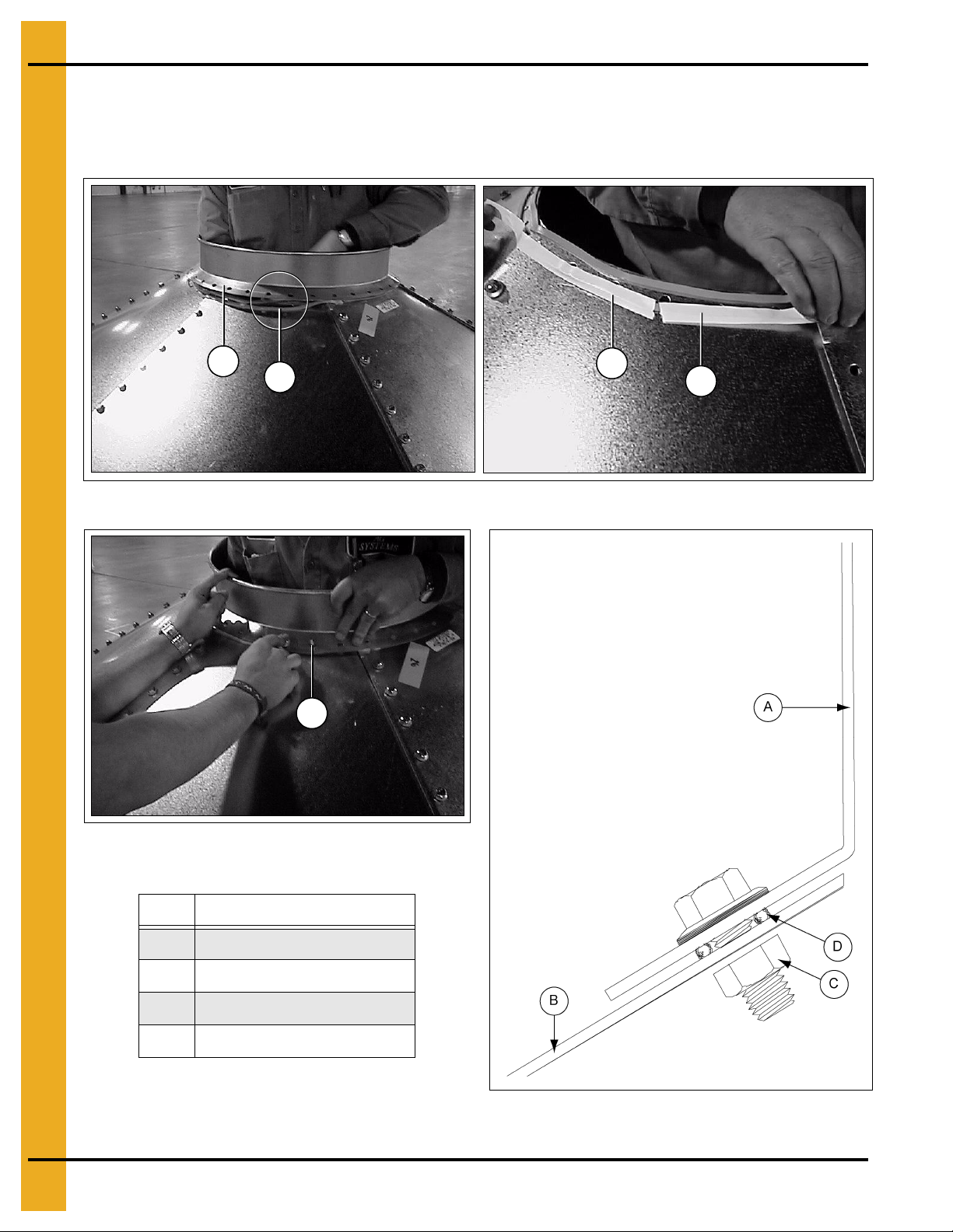
9' 60° Leg Attachment (for 9' 60° Tanks Only)
Curved washers are supplied in the hardware packages. These washers must be installed at the bottom
leg to sidewall bolt connection, to the inside of the hopper panel as shown in Figure 12C.
Apply caulking between the hopper panel and the sidewall sheet.
Figure 12C
Ref # Part # Description
A S-7484 Hex Nut 5/16"-18 JS Grade 5
B BLK-12483 10 Gauge Curved Washer
C S-10260 5/16" x 1" Bin Bolt
D Hopper Panel
E Sidewall Sheet
PNEG-1460 6', 7' and 9' Bulk Feed Tank BFT Series and GHT Series 63
Page 64

12. Hopper Assembly
Inside of tank
Inside of tank
Section A-A
Inside of tank
Reinforcement Angles
NOTE: Every hole in the hopper sheet will be utilized. Use 5/16" x 3/4" tru ss head bolt on ho pper seams.
(Truss head goes on inside of hopper.)
Only the 9' 3-6 ring, 60° and 7' 5-6 ring, 67° ring tanks use reinforcement angles.
NOTE: Last (bottom) bolt in reinforcement angle goes through hopper collar also.
Figure 12D
Figure 12E Hopper Overlap and Bolt Detail
with Reinforcement Angle
Ref # Description Ref # Description
A Reinforcement Angle D Hopper Sheet
B Hopper Panel
Figure 12F Hopper Overlap and Bolt Detail for Tanks
without Reinforcement Angle
E 5/16" x 3/4" Truss Head Bolt
C Caulking Two (2) Strips F Flange Nut
64 PNEG-1460 6', 7' and 9' Bulk Feed Tank BFT Series and GHT Series
Page 65

12. Hopper Assembly
Bolt detail hopper
extension (if used)
Bolt detail
hopper collar
Inside of tank
Inside of tank
Hopper Collar
Prior to attaching the final hopper panel, assemble the hopper extensions (if utilized) on the h opper collar.
Use 5/16" truss head bolts and caulk all joints on the assembly. Attach to the hopper panels using 5/16"
truss head bolts. Be sure to caulk between hopper extensions and hopper panels. (See Figure 12G and
Figure 12H.)
Figure 12G
Figure 12H
Ref # Description Ref # Description
A Hopper Panel E Hopper Extension
B 5/16" x 3/4" Truss Head Bolt F 16" or 22" Hopper or Hopper Extension (if Used)
C Flange Nut G 16" or 22" Hopper Collar
D Caulking
PNEG-1460 6', 7' and 9' Bulk Feed Tank BFT Series and GHT Series 65
Page 66

12. Hopper Assembly
22" Hopper Collar
45° 22" Hopper Collar (BLK-10854)
60° 22" Hopper Collar (BLK-10342)
67° 22" Hopper Collar (BLK-10341)
Install hopper collar before all hopper panels are assembled. Use 5/16" truss head bolts on all hopper
seams as shown in Figure 12I. Be sure to caulk between the hopper collar and hopper panels.
(See Figure 12I.)
Figure 12I
Ref # Description
A 22" Hopper Collar
16" Hopper Collar
6'-16" Hopper Collar 60° (BLK-10489) (24 Holes)
7'-16" Hopper Collar 67°(BLK-10488) (24 Holes)
* 9'-16" Hopper Collar 60° (BLK-11463) (27 Holes)
* NOTE: 9'-16" 60° Hopper collar (BLK-11463) is used with a 9'-16" 60° tank only. (27 Holes.)
Figure 12J
Ref # Description
A 16" Hopper Collar
66 PNEG-1460 6', 7' and 9' Bulk Feed Tank BFT Series and GHT Series
Page 67

Hopper Extension Kits
16" 45° Hopper Extension and Collar (BLK-10847) (Standard on 7' and 9' 45°)
16" 60° Hopper Extension and Collar (BLK-10587) (Optional)
16" 67° Hopper Extension and Collar (BLK-10591) (Optional)
12. Hopper Assembly
Figure 12K
Ref # Descrip t ion
A 16" Hopper Collar
B 22"-16" Hopper Extension
PNEG-1460 6', 7' and 9' Bulk Feed Tank BFT Series and GHT Series 67
Page 68

13. Legs and Leg Bracing
Leg
Tank Legs and Leg Braces
When installing legs to sidewall, reverse the normal insertion procedure for bolts. Place hex head and
neoprene washer to inside of sidewall, leaving threaded portion of bolt protruding outward. This provides
for a weather-tight seal at the leg attachment location. See Pages 68-72 for leg attachment to sidewall
sheet details.
Figure 13A
Use 5/16" x 1" bin bolts and nuts when attaching the leg to base. Make sure the washer is used on the slot
side of the leg.
Figure 13B
Ref # Part # Description
A BLK-10057 Back Leg Anchor Plate (One Tab)
B BLK-10058 Front Leg Anchor Plate (Two (2) Tabs)
68 PNEG-1460 6', 7' and 9' Bulk Feed Tank BFT Series and GHT Series
Page 69

Tank Legs and Leg Braces (Continued)
Line up leg with these holes and bolt 6' tank leg shown. (See Figure 13D.)
Inside of tank
Insert bolts inside to outside
on all leg to tank connections.
Leg
13. Legs and Leg Bracing
Figure 13C
Figure 13D
Ref # Description
A 5/16" x 1" Bin Bolt
Figure 13E
PNEG-1460 6', 7' and 9' Bulk Feed Tank BFT Series and GHT Series 69
Page 70

13. Legs and Leg Bracing
Failure to follow instructions may cause damage or failure of the equipment.
WARNING
13 Holes
10 Holes
Leg Size Chart
Tank Size Hopper # of Rings Length Leg Coverage
6' Diameter 60° 1-4 Rings 106-3/8" 1 Ring
7' Diameter 67° 1-4 Rings 140-1/2" 1 Ring
7' Diameter 67° 5-6 Rings 164-1/2" 1-3/4 Rings (56")
7' Diameter 45° 1-4 Rings 94-1/8" 1 Ring
7' Diameter 45° 5-6 Rings 120-3/4" 1-3/4 Rings (56")
9' Diameter 60° 1-5 Rings 140-1/2" 1 Ring
9' Diameter 60° 6 Rings 164-1/2" 1-3/4 Rings (56")
9' Diameter 45° 1-5 Rings 106-1/8" 1 Ring
9' Diameter 45° 6 Rings 132-3/4" 1-3/4 Rings (56")
* NOTE: 9' 5 Ring tanks must utilize 2 ring coverage legs if raising 8" (203.2 mm).
Depending on the size of the Bulk Feed Tank you are assembling, the leg will cover either the bottom
ring or 1-3/4 rings (56"). Refer to this chart to find the correct number of rings the legs will cover. Put all
legs on, but do not tighten bolts until all braces are in place. Be sure to put leg braces on properly.
(See Pages 72-75.)
1 Ring Leg 140-1/2" (3569 mm)
Figure 13F Leg Adjustment (7' (1-4 Ring) 67° and 9' (1-5 ring) 60° Only)
70 PNEG-1460 6', 7' and 9' Bulk Feed Tank BFT Series and GHT Series
Page 71

13. Legs and Leg Bracing
Failure to follow instructions may cause damage or failure of the equipment.
WARNING
22 Holes
19 Holes
Extra Clearance Leg Adjustment
In cases where extra clearance is required (on 7' 67° and 9' 60° tanks only), you may raise the tank up to
8" when installing the legs. See Figure 13G for proper positioning. Call company’s engineering for any
other special requirements.
* NOTE: If 7'-4 ring and 9'-4 ring 60° tanks are raised, they will require a safety cage ladder package.
2 Ring Leg 164-1/2" (4178 mm)
* NOTE: 9'-5 Ring tanks must utilize 2 ring coverage legs if raising 8" (203.2 mm).
Figure 13G Leg Adjustment (7' (5-6 Ring) 67° and 9' (6 Ring) 60° Only)
PNEG-1460 6', 7' and 9' Bulk Feed Tank BFT Series and GHT Series 71
Page 72

13. Legs and Leg Bracing
NOTE: 6' 60° Tanks require,
hopper braces only, no cross
ties are necessary.
NOTE: 7' 45° and 9' 45°
T anks require, hopper braces only,
no cross ties are necessary.
7' Leg 45°
9' Leg 45°
Bracing Hole Layout
For 7' 67° and 9' 60° feed tank bracing layout, See Pages 73-74.
Figure 13H 6' Leg 60° Figure 13I 7' and 9' 45° Legs
Ref # Description
A Ladder Standoff 3 Ring Tank
B 22" Hopper Brace
C 16" Hopper Brace
D La dder Standoff 4 Ring Tank
E Ladder Standoff 1-2 Ring Tank
F Anchor
72 PNEG-1460 6', 7' and 9' Bulk Feed Tank BFT Series and GHT Series
Ref # Description
A Ladder Standoff
B 22" Hopper Brace
C 1 6" Hopper Brace
D Ladder Standoff
E Anchor
Page 73

13. Legs and Leg Bracing
7' 67° 1-6 Ring
Figure 13J has been modified for clarity (not to scale). For 7' and 9' bracing notes, See Page 72.
Dimensions shown are measured from center of attachment holes in legs to bottom of leg. Use 3/8" nuts
and bolts to attach cross ties to each other and to leg. Hopper braces are attached to legs with 3/8" nuts
and bolts and to hopper collar with 5/16" hardware. Ladder standoffs are attached to legs with 5/16" nuts
and bolts. Do not tighten hardware until all bracing is in place.
Ref # Description
A 22" Hopper Brace 7/16" Diameter Hole
B Ladder Standoff 1-3-5 Rings 3/8" Diameter Hole
16" Hopper Brace (Raising Tank 8")
C
7/16" Diameter Hole
D Cross Tie Brace 7/16" Diameter Hole
E Ladder Standoff (All) 3/8" Diameter Hole
F Ladder Standoff 2-4-6 Rings 3/8" Diameter Hole
G 38.483" Between Hopper Braces
Figure 13J
PNEG-1460 6', 7' and 9' Bulk Feed Tank BFT Series and GHT Series 73
Page 74

13. Legs and Leg Bracing
9' 60° 2 Through 6 Ring Tank
Figure 13K has been modified for clarity (not to scale). For 7' and 9' bracing notes, See Page 72.
NOTE: 9' 5 Ring tanks must use 6 ring legs when raising 8" (203.2 mm).
Dimensions shown are measured from center of attachment holes in legs to bottom of leg. Use 3/8" nuts
and bolts to attach cross ties to each other and to leg. Hopper braces are attached to legs with 3/8" nuts
and bolts and to hopper collar with 5/16" hardware. Ladder standoffs are attached to legs with 5/16" nuts
and bolts. Do not tighten hardware until all bracing is in place.
Ref # Description
A 38-7/16" Between Hopper Braces
B Cross Tie Brace 7/16" Diameter Hole
C La dder Standoff 1-3-5 Rings 3/8" Diameter Hole
D 16" Hopper Brace 3/8" Diameter Hole
E Ladder Standoff 2-4-6 Rings 3/8" Diameter Hole
F 22" Hopper Brace 7/16" Diameter Hole
16" Hopper Brace (Raising Ta nk 8")
G
7/16" Diameter Hole
H La dder Standoff (All) 3/8" Diameter Hole
Figure 13K
74 PNEG-1460 6', 7' and 9' Bulk Feed Tank BFT Series and GHT Series
Page 75

13. Legs and Leg Bracing
Hopper to Leg Horizontal Bracing
BFT Brace Quantity
Tank Hopper Inside Cross Outside Cross
Description Brace Tie Brace Tie Brace
6' Diameter 60° Hopper 4 0 ** 0 **
7' Diameter 67° Hopper 4 4 4
7' Diameter 45° Hopper 4 0 ** 0 **
9' Diameter60° Hopper 6 6 6
9' Diameter 45° Hopper 6 0 ** 0 **
** NOTE: 6' 60°, 7' 45° and 9' 45° Tanks do not require cross tie braces.
All 6' 60°, all 7' 67° and all 9' 60° tanks utilize hopper bracing. Braces attach horizontally to the legs with
3/8" hardware and to the hopper with 5/16" hardware. (See Figure 13L and Figure 13M.)
Figure 13L
Figure 13M
Ref # Description
A Leg C 3/8" x 1" Bolt
B Hopper D 5/16" x 3/4" Truss Head Bolt (Head to Inside)
PNEG-1460 6', 7' and 9' Bulk Feed Tank BFT Series and GHT Series 75
Ref # Description
Page 76

13. Legs and Leg Bracing
Tank Legs and Leg Braces (Continued)
Figure 13N
Hopper braces are required on all hopper tanks and should be spaced equally around the tank. Refer to
chart below for the quantities required the tank.
T ank 16" Hopper 22" Hopper
Description Brace Part # Qty Brace Part # Qty
6' Diameter 60° Hopper BLK-12146 4 BLK-12147 4
7' Diameter 67° Hopper BLK-12107 4 BLK-12108 4
7' Diameter 45° Hopper BLK-12105 4 BLK-12106 4
9' Diameter 60° Hopper BLK-12109 6 BLK-12110 6
9' Diameter 45° Hopper BLK-12111 6 BLK-12112 6
NOTE: Hopper braces attach between the legs and the collar/hopper horizontal seam. Never bolt the
braces directly to the hopper seam above the collar. Use 16" braces with 16" collar and 22" braces
with 22" collars.
76 PNEG-1460 6', 7' and 9' Bulk Feed Tank BFT Series and GHT Series
Page 77

14. Raising Bin
Do not raise tank near power lines. Electrocution could occur if the tank came into
contact with live power lines.
WARNING
Bottom end view
Raising Bin to Set on Foundation
Preparing Bin
Just before standing the bin upright, peel protective mask off the decal while it is easy to reach. Mask may
become difficult to remove if left exposed to sunlight.
Check for all possible overhead obstructions, power line, etc., BEFORE standing the bin on
the foundation.
To prevent damage to legs when raising bin, brace them with 2" x 4" (50 mm x 100 mm) pieces of wood
as shown in Figure 14A. See the chart below for the correct length.
Bin Size 2" x 4" Length
6' Diameter (1829 mm) 51-3/8" (1305 mm)
7' Diameter (2134 mm) 59-7/8" (1521 mm)
9' Diameter (2743 mm) 52-1/8" (1324 mm)
PNEG-1460 6', 7' and 9' Bulk Feed Tank BFT Series and GHT Series 77
Figure 14A
Ref # Description
A Location of Cable or Sling Wrapped Around Tank
B Anchor or Stabilize to Prevent Sliding when Raising
Page 78

14. Raising Bin
NOTE: Leg shims are not standard equipment and must be obtained locally.
Raising Bin to Set on Foundation (Continued)
Be sure that all bolts are tightened properly. Bulk Feed Tank can now be set up on foundation. Small Bulk
Feed Tanks may be set up with manpower. As the tanks get taller and heavier, other means must be
used to raise the Bulk Feed Tank. A small crane of adequate capacity attached to a cable or sling
secured around the Bulk Feed Tank just above the legs will usually do the job. Refer any questions to a
qualified rigger.
Standard Hopper Bin Anchoring
Measure between opposite legs to be sure they are an equal distance apart before securing the bin with
anchor bolts. Follow the chart shown below. Failure to do so may cause damage to the bin.
Bin Size Distance Between Opposite Legs
6' Diameter (1829 mm) 72-1/4" (1835 mm)
7' Diameter (2134 mm) 84-1/4" (2140 mm)
9' Diameter (2743 mm) 108-1/8" (2746 mm)
Figure 14B
78 PNEG-1460 6', 7' and 9' Bulk Feed Tank BFT Series and GHT Series
Page 79

14. Raising Bin
Raising Bin to Set on Foundation (Continued)
Anchoring Tank
Check all legs to see if shims are necessary to level the tank properly. After Bulk Feed Tank is level and
shimmed properly, anchor the tank down with 5/8" washers and nuts. (See Figure 14C.)
Figure 14C
Ref # Part # Description
A S-836 5/8" Nut (Not Supplied)
B S-858 5/8" Washer (Not Supplied)
PNEG-1460 6', 7' and 9' Bulk Feed Tank BFT Series and GHT Series 79
Page 80

14. Raising Bin
NOTE: Grounding rod must be placed
a minimum of 24" from concrete.
Bin Grounding Instructions
NOTE: Parts are not supplied by manufacturer. They should be purchased locally.
All bins shall have two (2) ground connections. Ground clamps must be placed at equal distances around
the bin.
Alternate Installation: Cables may be placed in the foundation or through PVC sleeve inserted in the slab
during construction.
Figure 14D
Ref # Description Ref # Description
A Cable Clamp E Number 2 Minimum (Typical)
B 5' (1524 mm) Copper Cable (Plain or Jacketed)
C Grou nd Rod Clamp G 10'-0" Minimum (3048 mm)
D Grou nd Rod 1/2" x 10' (3048 mm)
80 PNEG-1460 6', 7' and 9' Bulk Feed Tank BFT Series and GHT Series
F 12" (305 mm)
H 9'-0" Minimum (2743 mm)
Page 81

Pneumatic Fill Kit Assembly
NOTE: Inlet and exhaust parts from roof eave upward supplied with kit.
15. Pneumatic Fill Kit
Figure 15A
Ref # Description
A Fill
B Exhaust
C 5/16" Square Neck Bolt
D Hex Nut 5/16"-1 8 JS Grade 5 (S-7484)
E Cupped Washer
F Fill Tube is 4" Diameter (Available)
G Exhaust Tube is 6" Diameter
PNEG-1460 6', 7' and 9' Bulk Feed Tank BFT Series and GHT Series 81
Page 82

15. Pneumatic Fill Kit
Roof Panel
Identical pre-punched roof panels are available from the manufacturer for inlet and outlet sections of
pneumatic fill systems. Extruded lip of the panels provide for weather-tight installation. Caulking placed
between angle rings virtually eliminates all leakage problems. Rubber seal must be utilized at roof cap
area to prevent material “blow by” from pressurized systems.
To install fill kits in roof panels not pre-punched, cut 5-5/8" (143 mm) diameter holes in opposing roof
panels as shown. Caulk sufficiently to provide weather-tight seal.
Refer to PNEG-1904, that is included in the pneumatic fill kits for information on installation of the cap latch
and lid sealing components.
Figure 15B
82 PNEG-1460 6', 7' and 9' Bulk Feed Tank BFT Series and GHT Series
Page 83

1. 6' Diameter 60° Hopper Bin Specifications - (See Pages 84-85.)
2. 6' Diameter 60° Hopper Bin Hardware Specifications - (See Pages 86-87.)
3. 7' Diameter 67° Hopper Bin Specifications - (See Pages 88-89.)
4. 7' Diameter 67° Hopper Bin Hardware Specifications - (See Pages 90-91.)
5. 7' Diameter 45° Hopper Bin Specifications - (See Pages 92-93.)
6. 7' Diameter 45° Hopper Bin Hardware Specifications - (See Pages 94-95.)
7. 9' Diameter 60° Hopper Bin Specifications - (See Pages 96-97.)
8. 9' Diameter 60° Hopper Bin Hardware Specifications - (See Pages 98-99.)
16. Parts List
9. 9' Diameter 45° Hopper Bin Specifications - (See Pages 100-101.)
10. 9' Diameter 45° Hopper Bin Hardware Specifications - (See Pages 102-103.)
PNEG-1460 6', 7' and 9' Bulk Feed Tank BFT Series and GHT Series 83
Page 84

16. Parts List
6' Diameter 60° Hopper Bin Specifications
Under Collar Clearance
16" Collar 28-5/16" (719 mm)
22" Collar 32 -7/8" (837 mm)
IMPORTANT: Bolt heads are inside of bin at the leg to body attachment and on all vertical seams on
hopper panels. All bolts to be tightened from the nut side only. Refer to detail on Pa ge 22
for location of caulking. No cross tie bracing required.
84 PNEG-1460 6', 7' and 9' Bulk Feed Tank BFT Series and GHT Series
Page 85

16. Parts List
6' Diameter 60° Hopper Bin Specifications Parts List
Ref # Part # Description Qty
1 BLK-12254 6' 30° Roof Panel (20 Gauge) (Shown) 6
1 BLK-12257 6' 40° Roof Panel (20 Gauge) 6
2 6' Sidewall Sheet 2 Per Ring
2 SS40682006 20 Gauge (Top Punched Sidewall Sheet)
2 SS41632006 20 Gauge (Top Punched Decal Sidewall Sheet)
2 SS40672006 20 Gauge (Bottom/Top Leg Sidewall Sheet)
2 SS40692006 20 Gauge (Middle Punched Sidewall Sheet)
2 SS41622006 20 Gauge (Bottom/Top Leg Decal Sidewall Sheet)
2 SS40712006 20 Gauge (Bottom Leg Sidewall Sheet)
2 SS40711806 18 Gauge (Bottom Leg Sidewall Sheet)
3 BLK-11475 6' 60° Offset Hopper Panel 16" Opening (20 Gauge) (Shown) 6
3 BLK-10358 6' 60° Hopper Panel 22" Opening (20 Gauge) 6
4 BLK-12222 6' 60° Leg 106-1/16" (12 Gauge) (1-4 Ring) 4
5 BLK-12146 Hopper Brace for 16" Collar (Shown) 4
5 BLK-12147 Hopper Brace for 22" Collar 4
6 BLK-10489 16" 60° Hopper Collar (24 Holes) (Shown) 1
6 BLK-10342 22" 60° Hopper Collar (36 Holes) 1
7 BLK-11730 30° Bulk Tank Peak Ring (Shown) 1
7 BLK-12534 40° Bulk Tank Peak Ring 1
PNEG-1460 6', 7' and 9' Bulk Feed Tank BFT Series and GHT Series 85
Page 86

16. Parts List
6' Diameter 60° Hopper Bin Hardware Specifications
86 PNEG-1460 6', 7' and 9' Bulk Feed Tank BFT Series and GHT Series
Page 87

16. Parts List
* NOTE: Bolt listed first and nut second for each usage.
Hardware usage: Heads of bolts are on the outside of tank unless otherwise noted.
6' Diameter 60° Hopper Bin Hardware Specifications Parts List
Ref # Part # Description Qty
1 S-10260
1 S-7484 36
2 S-10260
2 S-7484 48
3 S-10260
3 S-7484 72
4 S-10260
4 S-7484 Varies
5 S-10260
5 S-7484 Varies
6 S-10260
6 S-7484 48
7 S-10260 Hopper Panels to Sidewall Sheet (Use 5/16" x 1" Hex Head Bin Bolts
7 S-7484 72
8 S-10267
8 S-10268 108
Bulk Tank Peak Ring to Roof Panels (Use 5/16" x 1" Hex Head Bin Bolts and
5/16" Hex Nuts.)
Roof Panel to Roof Panel (Use 5/16" x 1" Hex Head Bin Bolts and 5/16" Hex Nuts.)
Roof Panels to Top Sidewall Sheets (Use 5/16" x 1" Hex Head Bin Bolts and
5/16" Hex Nuts.)
Vertical Sidewall Sheet Seams (Use 5/16" x 1" Hex Head Bin Bolts and
5/16" Hex Nuts.)
Horizontal Sidewall Sheet Seams (Use 5/16" x 1" Hex Head Bin Bolts and
5/16" Hex Nuts.)
Leg to Sidewall Sheet (Use 5/16" x 1" Hex Head Bin Bolts and 5/16" Hex Nuts.)
(Bolt Heads to Inside of Tank.)
and 5/16" Hex Nuts.) (Bolt Head to Inside at Leg to Hopper to Sidewall
Connection Only.)
Vertical Hopper Seams (Use 5/16" x 3/4" Truss Head Bin Bolts and 5/16"
Flanged Whiz Nuts.) (Bolt Heads to Inside of Tank.)
36
48
72
Varies
Varies
48
72
108
9 S-10267
9 S-10268 24 or 36
10 S-7485
10 S-7489 4
Ref # Description Ref # Description
Hopper Collar to Hopper Panel (Use 5/16" x 3/4" Truss Head Bin Bolts and 5/16"
Flanged Whiz Nuts.) (Bolt Heads to Inside of Tank.) (16" Shown.)
Hopper Brace to Leg (Use 3/8" x 1" Flange Head Bolts and 3/8" Hex Nuts.)
A Inside G Leg
B Outside
C Roof Sheet I Hopper Sheet
D Body Sheet
E Peak Ring Collar K Hopper Brace
F Hopper Panel
H Offset Hopper Panel
J Hopper Collar
24 or 36
4
PNEG-1460 6', 7' and 9' Bulk Feed Tank BFT Series and GHT Series 87
Page 88
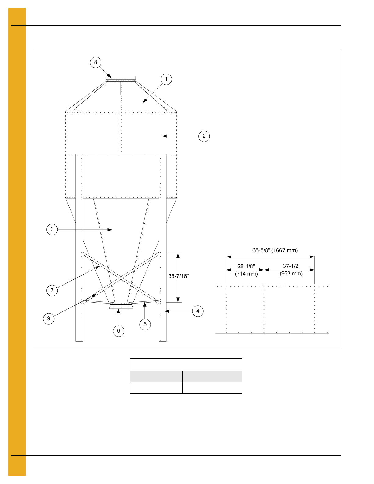
16. Parts List
Leg holes
Leg holes
7' Diameter 67° Hopper Bin Specifications
Under Collar Clearance
16" Collar 30-3/8" (771 mm)
22" Collar 36 -1/2" (927 mm)
IMPORTANT: Vertical seams of body sheets with leg holes MUST be bolted together to provide 65-5/8"
(1667 mm) between leg holes.
IMPORTANT: Bolt heads are inside of bin at the leg to body attachment and on all vertical seams on
hopper panels. All bolts to be tightened from the nut side only. Refer to detail on Pa ge 22
for location of caulking. No cross tie bracing required.
88 PNEG-1460 6', 7' and 9' Bulk Feed Tank BFT Series and GHT Series
Page 89

16. Parts List
7' Diameter 67° Hopper Bin Specifications Parts List
Ref # Part # Description Qty
1 BLK-12260 7' 30° Roof Panel (20 Gauge) (Shown) 6
1 BLK-12263 7' 40° Roof Panel (20 Gauge) 6
2 7' Sidewall Sheet 2 Per Ring
2 SS40602007 20 Gauge (Bottom/Top Leg Punched Sidewall Sheet)
2 SS41642007 20 Gauge (Bottom/Top Leg Punched Decal Sidewall Sheet)
2 SS40612007 20 Gauge (Top Punched Sidewall Sheet)
2 SS41652007 20 Gauge (Top Punched Decal Sidewall Sheet)
2 SS40462007 20 Gauge (Middle Punched Sidewall Sheet)
2 SS40461807 18 Gauge (Middle Punched Sidewall Sheet)
2 SS40461707 17 Gauge (Middle Punched Sidewall Sheet)
2 SS40641707 17 Gauge (Middle Leg Punched Sidewall Sheet)
2 SS40641507 15 Gauge (Middle Leg Punched Sidewall Sheet)
2 SS40661807 18 Gauge (Bottom Leg Punched Sidewall Sheet)
2 SS40661707 17 Gauge (Bottom Leg Punched Sidewall Sheet)
2 SS40661507 15 Gauge (Bottom Leg Punched Sidewall Sheet)
3 BLK-11476 7' 67° Offset Hopper Panel 16" Opening (18 Gauge) (Shown) 6
3 BLK-10569 7' 67° Hopper Panel 22" Opening (18 Gauge) 6
4 BLK-12039 7' Leg 140-1/2" (12 Gauge) (1-4 Rings) (Shown) 4
4 BLK-12040 7' Leg 164-1/2" (10 Gauge) (5-6 Rings) 4
5 BLK-12107 Hopper Brace for 16" Collar (Shown) 4
5 BLK-12108 Hopper Brace for 22" Collar 4
6 BLK-10488 16" 67° Hopper Collar (Shown) 1
6 BLK-10341 22" 67° Hopper Collar (36 Holes) 1
7 BLK-12056 7' Inside Cross Tie Brace (72.49") (12 Gauge) 4
7 BLK-12057 7' Outside Cross Tie Brace (72.49") (12 Gauge) 4
8 BLK-11730 30° Bulk Tank Peak Ring (Shown) 1
8 BLK-12534 40° Bulk Tank Peak Ring 1
9 BLK-12009 7' 67° Hopper Reinforcement Angle (5-6 Ring Tanks Only) 6
PNEG-1460 6', 7' and 9' Bulk Feed Tank BFT Series and GHT Series 89
Page 90

16. Parts List
7' Diameter 67° Hopper Bin Hardware Specifications
90 PNEG-1460 6', 7' and 9' Bulk Feed Tank BFT Series and GHT Series
Page 91

16. Parts List
* NOTE: Bolt listed first and nut second for each usage.
Hardware usage: Heads of bolts are on the outside of tank unless otherwise noted.
7' Diameter 67° Hopper Bin Hardware Specifications Parts List
Ref # Part # Description Qty
1 S-10260
1 S-7484 36
2 S-10260
2 S-7484 60
3 S-10260
3 S-7484 84
4 S-10260
4 S-7484 Varies
5 S-10260
5 S-7484 Varies
6 S-10260
6 S-7484 52 or 88
7 S-10260 Hopper Panels to Sidewall Sheet (Use 5/16" x 1" Hex Head Bin Bolts
7 S-7484 84
8 S-10267
8 S-10268 162
Bulk Tank Peak Ring to Roof Panels (Use 5/16" x 1" Hex Head Bin Bolts and
5/16" Hex Nuts.)
Roof Panel to Roof Panel (Use 5/16" x 1" Hex Head Bin Bolts and 5/16" Hex Nuts.)
Roof Panels to Top Sidewall Sheets (Use 5/16" x 1" Hex Head Bin Bolts and
5/16" Hex Nuts.)
Vertical Sidewall Sheet Seams (Use 5/16" x 1" Hex Head Bin Bolts and
5/16" Hex Nuts.)
Horizontal Sidewall Sheet Seams (Use 5/16" x 1" Hex Head Bin Bolts and
5/16" Hex Nuts.)
Leg to Sidewall Sheet (Use 5/16" x 1" Hex Head Bin Bolts and 5/16" Hex Nuts.)
(Bolt Heads to Inside of Tank.)
and 5/16" Hex Nuts.) (Bolt Head to Inside at Leg to Hopper to Sidewall
Connection Only.)
Vertical Hopper Seams (Use 5/16" x 3/4" Truss Head Bin Bolts and 5/16"
Flanged Whiz Nuts.) (Bolt Heads to Inside of Tank.)
36
60
84
Varies
Varies
52 or 88
84
162
9 S-10267
9 S-10268 24 or 36
10 S-7485
10 S-7489 4
11 S-7485
11 S-7489 12
Ref # Description
A Inside G Leg
B Outside
C Ro of Sheet I Leg Cross Tie
DBody Sheet
E Peak Ring Collar K Hopper Collar
F Hopper Panel
Hopper Collar to Hopper Panel (Use 5/16" x 3/4" Truss Head Bin Bolts and 5/16"
Flanged Whiz Nuts.) (Bolt Heads to Inside of Tank.) (16" Shown.)
Hopper Brace to Leg (Use 3/8" x 1" Flange Head Bolts and 3/8" Hex Nuts.)
Cross Tie Brace (Use 3/8" x 1" Flange Head Bolts and 3/8" Hex Nuts.)
Ref # Description
H Hopp er Reinforcement Angle (5-6 Rings Only)
J Offset Hopper Panel
L Hopper Brace
24 or 36
4
12
PNEG-1460 6', 7' and 9' Bulk Feed Tank BFT Series and GHT Series 91
Page 92

16. Parts List
7' Diameter 45° Hopper Bin Specifications
Under Collar Clearance
16" Collar 29-3/4" (756 mm)
22" Collar 32-5/16" (821 mm)
IMPORTANT: Bolt heads are inside of bin at the leg to body attachment and on all vertical seams on
hopper panels. All bolts to be tightened from the nut side only. Refer to detail on Pa ge 22
for location of caulking. No cross tie bracing required.
92 PNEG-1460 6', 7' and 9' Bulk Feed Tank BFT Series and GHT Series
Page 93

16. Parts List
7' Diameter 45° Hopper Bin Specifications Parts List
Ref # Part # Description Qty
1 BLK-12260 7' 30° Roof Panel (20 Gauge) (Shown) 6
1 BLK-12263 7' 40° Roof Panel (20 Gauge) 6
2 7' Sidewall Sheet 2 Per Ring
2 SS40602007 20 Gauge (Bottom/Top Leg Punched Sidewall Sheet)
2 SS41642007 20 Gauge (Bottom/Top Leg Punched Decal Sidewall Sheet)
2 SS40612007 20 Gauge (Top Punched Sidewall Sheet)
2 SS41652007 20 Gauge (To p Punched Decal Sidewall Sheet)
2 SS40462007 20 Gauge (Middle Punched Sidewall Sheet)
2 SS40461807 18 Gauge (Middle Punched Sidewall Sheet)
2 SS40461707 17 Gauge (Middle Punched Sidewall Sheet)
2 SS40641707 17 Gauge (Middle Leg Punched Sidewall Sheet)
2 SS40641507 15 Gauge (Middle Leg Punched Sidewall Sheet)
2 SS40661807 18 Gauge (Bottom Leg Punched Sidewall Sheet)
2 SS40661707 17 Gauge (Bottom Leg Punched Sidewall Sheet)
2 SS40661507 15 Gauge (Bottom Leg Punched Sidewall Sheet)
3 BLK-10693 7' 45° Offset Hopper Panel 22" Opening (18 Gauge) (Shown) 6
4 BLK-12041 7' Leg 94-1/8" (12 Gauge) (1-4 Rings) (Shown) 4
4 BLK-12042 7' Leg 120-3/4" (10 Gauge) (5-6 Rings) 4
5 BLK-12105 Hopper Brace for 16" Collar (Shown) 4
5 BLK-12106 Hopper Brace for 22" Collar 4
6 BLK-10696 16" 45° Hopper Collar (24 Holes) (Shown) 1
6 BLK-10854 22" 45° Hopper Collar (36 Holes) 1
7 BLK-11730 30° Bulk Tank Peak Ring (Shown) 1
7 BLK-12534 40° Bulk Tank Peak Ring 1
PNEG-1460 6', 7' and 9' Bulk Feed Tank BFT Series and GHT Series 93
Page 94

16. Parts List
7' Diameter 45° Hopper Bin Hardware Specifications
94 PNEG-1460 6', 7' and 9' Bulk Feed Tank BFT Series and GHT Series
Page 95

16. Parts List
* NOTE: Bolt listed first and nut second for each usage.
Hardware usage: Heads of bolts are on the outside of tank unless otherwise noted.
7' Diameter 45° Hopper Bin Hardware Specifications Parts List
Ref # Part # Description Qty
1 S-10260
1 S-7484 36
2 S-10260
2 S-7484 60
3 S-10260
3 S-7484 84
4 S-10260
4 S-7484 Varies
5 S-10260
5 S-7484 Varies
6 S-10260
6 S-7484 48 or 88
7 S-10260 Hopper Panels to Sidewall Sheet (Use 5/16" x 1" Hex Head Bin Bolts
7 S-7484 84
Bulk Tank Peak Ring to Roof Panels (Use 5/16" x 1" Hex Head Bin Bolts and
5/16" Hex Nuts.)
Roof Panel to Roof Panel (Use 5/16" x 1" Hex Head Bin Bolts and 5/16" Hex Nuts.)
Roof Panels to Top Sidewall Sheets (Use 5/16" x 1" Hex Head Bin Bolts and
5/16" Hex Nuts.)
Vertical Sidewall Sheet Seams (Use 5/16" x 1" Hex Head Bin Bolts and
5/16" Hex Nuts.)
Horizontal Sidewall Sheet Seams (Use 5/16" x 1" Hex Head Bin Bolts and
5/16" Hex Nuts.)
Leg to Sidewall Sheet (Use 5/16" x 1" Hex Head Bin Bolts and 5/16" Hex Nuts.)
(Bolt Heads to Inside of Tank.)
and 5/16" Hex Nuts.) (Bolt Head to Inside at Leg to Hopper to Sidewall
Connection Only.)
36
60
84
Varies
Varies
48 or 88
84
8 S-10267
8 S-10268 102
9 S-10267
9 S-10268 24 or 36
10 S-7485
10 S-7489 4
Ref # Description
A Inside F Hopper Panel
B Outside
C Ro of Sheet H Offset Hopper Panel
DBody Sheet
E Peak Ring Collar J Hopper Brace
Vertical Hopper Seams (Use 5/16" x 3/4" Truss Head Bin Bolts and 5/16"
Flanged Whiz Nuts.) (Bolt Heads to Inside of Tank.)
Hopper Collar to Hopper Panel (Use 5/16" x 3/4" Truss Head Bin Bolts and 5/16"
Flanged Whiz Nuts.) (Bolt Heads to Inside of Tank.) (16" Shown.)
Hopper Brace to Leg (Use 3/8" x 1" Flange Head Bolts and 3/8" Hex Nuts.)
Ref # Description
GLeg
I Hopper Collar
102
24 or 36
4
PNEG-1460 6', 7' and 9' Bulk Feed Tank BFT Series and GHT Series 95
Page 96

16. Parts List
9' Diameter 60° Hopper Bin Specifications
Under Collar Clearance
16" Collar 28-1/16" (713 mm)
22" Collar 32 -5/8" (829 mm)
IMPORTANT: Bolt heads are inside of bin at the Leg to Body attachment and on all vertical seams on
hopper panels. All bolts to be tightened from the nut side only. Refer to detail on Pa ge 22
for location of caulking.
96 PNEG-1460 6', 7' and 9' Bulk Feed Tank BFT Series and GHT Series
Page 97

16. Parts List
9' Diameter 60° Hopper Bin Specifications Parts List
Ref # Part # Description Qty
1 BLK-12266 9' 30° Roof Panel (20 Gauge) (Shown) 9
1 BLK-12269 9' 40° Roof Panel (20 Gauge) 9
2 9' Sidewall Sheet 3 Per Ring
2 SS40682009 20 Gauge (Top Punched Sidewall Sheet)
2 SS41662009 20 Gauge (Top Punched Decal Sidewall Sheet)
2 SS40692009 20 Gauge (Middle Punched Sidewall Sheet)
2 SS40691809 18 Gauge (Middle Punched Sidewall Sheet)
2 SS40691709 17 Gauge (Middle Punched Sidewall Sheet)
2 SS40701509 15 Gauge (Middle Leg Punched Sidewall Sheet)
2 SS40712009 20 Gauge (Bottom Leg Punched Sidewall Sheet)
2 SS40711809 18 Gauge (Bottom Leg Punched Sidewall Sheet)
2 SS40711709 17 Gauge (Bottom Leg Punched Sidewall Sheet)
2 SS40711509 15 Gauge (Bottom Leg Punched Sidewall Sheet)
3 BLK-12311 9' 60° Offset Hopper Panel 16" Opening (18 Gauge) (Shown) 9
3 BLK-12313 9' 60° Hopper Panel 22" Opening (18 Gauge) 9
4 BLK-12036 9' Leg 140-1/2" (12 Gauge) (2-5 Rings) (Shown) 6
4 BLK-12037 9' Leg 164-1/2" (10 Gauge) (6 Rings) 6
5 BLK-12109 Hopper Brace for 16" Collar (Shown) 6
5 BLK-12110 Hopper Brace for 22" Collar 6
6 BLK-12342 16" 60° Hopper Collar (18 Holes) (Shown) 1
6 BLK-10342 22" 60° Hopper Collar (36 Holes) 1
7 BLK-12058 9' Inside Cross Tie Brace (67.788") (12 Gauge) 6
7 BLK-12059 9' Outside Cross Tie Brace (67.788") (12 Gauge) 6
8 BLK-11730 30° Bulk Tank Peak Ring (Shown) 1
8 BLK-12534 40° Bulk Tank Peak Ring 1
9 BLK-12730 9' 60° Hopper Reinforcement Angle (3-6 Ring Tanks Only) 9
PNEG-1460 6', 7' and 9' Bulk Feed Tank BFT Series and GHT Series 97
Page 98

16. Parts List
9' Diameter 60° Hopper Bin Hardware Specifications
98 PNEG-1460 6', 7' and 9' Bulk Feed Tank BFT Series and GHT Series
Page 99

16. Parts List
* NOTE: Bolt listed first and nut second for each usage.
Hardware usage: Heads of bolts are on the outside of tank unless otherwise noted.
9' Diameter 60° Hopper Bin Hardware Specifications Parts List
Ref # Part # Description Qty
1 S-10260
1 S-7484 36
2 S-10260
2 S-7484 108
3 S-10260
3 S-7484 108
4 S-10260
4 S-7484 Varies
5 S-10260
5 S-7484 Varies
6 S-10260
6 S-7484 78 or 132
7 S-10260 Hopper Panels to Sidewall Sheet (Use 5/16" x 1" Hex Head Bin Bolts and
7 S-7484 108
8 S-10260
8 S-7484 6
8 BLK-12483 6
Bulk Tank Peak Ring to Roof Panels (Use 5/16" x 1" Hex Head Bin Bolts and
5/16" Hex Nuts.)
Roof Panel to Roof Panel (Use 5/16" x 1" Hex Head Bin Bolts and 5/16" Hex Nuts.)
Roof Panels to Top Sidewall Sheets (Use 5/16" x 1" Hex Head Bin Bolts and
5/16" Hex Nuts.)
Vertical Sidewall Sheet Seams (Use 5/16" x 1" Hex Head Bin Bolts and
5/16" Hex Nuts.)
Horizontal Sidewall Sheet Seams (Use 5/16" x 1" Hex Head Bin Bolts and
5/16" Hex Nuts.)
Leg to Sidewall Sheet (Use 5/16" x 1" Hex Head Bin Bolts and 5/16" Hex Nuts.)
(Bolt Heads to Inside of Tank.)
5/16" Hex Nuts.) (Bolt Head to Inside at Leg to Hopper to Sidewall
Connection Only.)
Leg to Body Sheet to Hopper Connection (Use 10 Gauge Washer under
5/16" x 1" Hex Head Bin Bolts and 5/16" Hex Nuts.) (Bolt Head to Inside at Leg to
Hopper to Sidewall Connection Only.)
36
108
108
Varies
Varies
78 or 132
108
6
9 S-10267
9 S-10268 216
10 S-7485
10 S-7489 18
11 S-7485
11 S-7489 6
12 S-10267
12 S-10268 27 or 36
Ref # Description Ref # Description
A Inside G Leg
B Outside
C Roof Panel I Cross Tie
D S idewall Sheet
E Peak Ring Collar K Hopper Collar
F Hopper Panel
Vertical Hopper Seams (Use 5/16" x 3/4" Truss Head Bin Bolts and 5/16"
Flanged Whiz Nuts.) (Bolt Heads to Inside of Tank.)
Cross Tie Brace (Use 3/8" x 1" Flange Head Bolts and 3/8" Hex Nuts.)
Hopper Brace to Leg (Use 3/8" x 1" Flange Head Bolts and 3/8" Hex Nuts.)
Hopper Collar to Hopper Panel (Use 5/16" x 3/4" Truss Head Bin Bolts and
5/16" Flanged Whiz Nuts.) (Bolt Heads to Inside of Tank.) (16" Shown.)
H Washer
J Offset Hopper Panel
L Hopper Brace
216
18
6
27 or 36
PNEG-1460 6', 7' and 9' Bulk Feed Tank BFT Series and GHT Series 99
Page 100

16. Parts List
9' Diameter 45° Hopper Bin Specifications
Under Collar Clearance
16" Collar 30-11/16" (779 mm)
22" Collar 33 -1/4" (844 mm)
IMPORTANT: Bolt heads are inside of bin at the leg to body attachment and on all vertical seams on
hopper panels. All bolts to be tightened from the nut side only. Refer to detail on Pa ge 22
for location of caulking. No cross tie bracing required.
100 PNEG-1460 6', 7' and 9' Bulk Feed Tank BFT Series and GHT Series
 Loading...