

Page 1
Operation
Manual
PNEG-1459
Date: 8-01-2008
L Series Dryer
Operation Manual
PNEG-1459
Page 2

2
PNEG-1459 L Series Operators
Page 3

CONTENTS
INTRODUCTION..................................................................................................................................................4
OPERATING PRECAUTIONS................................................................................................................................................4
SAFETY...............................................................................................................................................................................5
SAFETY ALERT SYMBOL....................................................................................................................................................5
EMERGENCY STOP SWITCH.............................................................................................................................................5
SAFETY DECALS.................................................................................................................................................................5
SPECIFICATIONS.................................................................................................................................................7
DRYER DIMENSIONS...........................................................................................................................................................7
SPECIFICATION CHARTS....................................................................................................................................................8
VISION CONTROL PANEL................................................................................................................................9
CONTROL POWER SWITCH...............................................................................................................................................9
FAN SWITCH........................................................................................................................................................................9
HEATER SWITCH.................................................................................................................................................................9
LOAD AUGER SWITCH.....................................................................................................................................................10
UNLOAD SWITCH..............................................................................................................................................................10
OUTSIDE LIGHT SWITCH.................................................................................................................................................10
START SWITCH...................................................................................................................................................................10
STOP SWITCH.....................................................................................................................................................................10
VISION TOUCH SCREEN DISPLAY...............................................................................................................11
BOOT SCREEN....................................................................................................................................................................11
DEFAULT OPERATION SCREEN......................................................................................................................................11
OPTIONAL OPERATION SCREEN....................................................................................................................................12
SETTING THE TIMERS......................................................................................................................................................13
SETTING THE TEMPERATURES........................................................................................................................................13
THE SETUP SCREEN..........................................................................................................................................................14
VIEWING THE OWNERS MANUALS ON THE DISPLAY SCREEN...............................................................................16
VIEWING THE DRYER SHUTDOWN HISTORY...............................................................................................................16
TEST FIRING.......................................................................................................................................................17
DRYER PRESEASON CHECKS..........................................................................................................................................17
INSPECT THE METERING ROLLS....................................................................................................................................17
ELECTRICAL POWER........................................................................................................................................................17
CONTROL POWER SWITCH..............................................................................................................................................17
START SWITCH..................................................................................................................................................................17
FUEL CHECK......................................................................................................................................................................17
UNLOAD AUTO OPERATION...................................................................................................................................18
UNLOAD MANUAL OPERATION...........................................................................................................................18
METER ROLL OPERATION.......................................................................................................................................18
FAN SWITCHES.........................................................................................................................................................18
BURNER SAFETY.......................................................................................................................................................18
BURNER TEST FIRE...................................................................................................................................................18
DRYER SHUTDOWN..................................................................................................................................................19
EMERGENCY..............................................................................................................................................................19
DRYER OPERATION - START-UP...................................................................................................................20
DRYER OPERATION - BASIC MOISTURE CONTROL............................................................................22
DRYER OPERATION - INTERMEDIATE MOISTURE CONTROL..........................................................26
DRYER OPERATION - ADVANCED MOISTURE CONTROL...................................................................30
DRYING TIME TABLES.....................................................................................................................................36
ILLUSTRATIONS...............................................................................................................................................38
SERVICE..........................................................................................................................................................................44
SEASONAL INSPECTION AND SERVICE.................................................................................................................44
LUBRICATION PROCEDURE....................................................................................................................................45
SUGGESTED LUBRICATION SCHEDULE................................................................................................................45
PROPANE VAPORIZER SEASONAL INSPECTION..................................................................................................46
MAIN CONTROLS......................................................................................................................................................46
HOW TO CLEAR A JAMMED METER ROLL...........................................................................................................46
SAFETY CIRCUIT SHUTDOWN MESSAGES.........................................................................................................47
FAN HEATER GENERATED ERRORS.......................................................................................................................47
INPUT/OUTPUT GENERATED ERRORS................................................................................................................48
MASTER DISPLAY GENERATED ERRORS...............................................................................................................49
WARRANTY....................................................................................................................................................................53
PNEG-1459 L Series Operators
3
Page 4

INTRODUCTION
OPERATING PRECAUTIONS
READ THESE INSTRUCTIONS BEFORE
INSTALLATION and OPERATION.
SAVE FOR FUTURE REFERENCE.
Thank you for choosing a GSI Vision Series grain dryer. These units are among the finest grain dryers ever built;
designed to give you excellent operating performance and reliable service for many years.
This manual describes the installation and operation for all standard production model dryers. These dryers are
available with liquid propane or natural gas fuel supply, single phase 230 volt, three phase 230 or 460 volt (60Hz) electrical
power.
USE CAUTION IN THE OPERATION OF THIS
EQUIPMENT
The design and manufacture of this dryer is directed toward operator safety. However, the very nature of a grain dryer
having a gas burner, high voltage electrical equipment and high speed rotating parts does present a hazard to personnel which
cannot be completely safeguarded against without interfering with efficient operation and reasonable access to components.
Use extreme caution in working around high speed fans, gas-fired heaters, augers and auxiliary conveyors which may
start without warning when the dryer is operating on automatic control.
Continued safe dependable operation of automatic equipment depends, to a great degree, upon the owner. For a safe
and dependable drying system, follow the recommendations within the manual and make it a practice to regularly inspect the
operation of the unit for any developing problems or unsafe conditions.
Take special note of the Operating Precautions listed below before attempting to operate the dryer.
Keep the dryer clean. Do not allow fine material to accumulate in the plenum chamber.
A CAREFUL OPERATOR IS THE BEST INSURANCE AGAINST AN ACCIDENT.
OPERATING PRECAUTIONS
1. Read and understand the operation manual before attempting to operate the unit.
2. Keep ALL guards, safety decals, and safety devices in place. Never operate dryer while guards are removed.
3. Keep visitors, children and untrained personnel away from dryer at all times.
4. Never attempt to operate the dryer by jumping or otherwise bypassing any safety devices on the unit.
5. Always set the main power supply disconnect switch to OFF and lock it in the OFF position using a padlock before
performing any service or maintenance work on the dryer or the auxiliary conveyor equipment.
6. Before attempting to remove and reinstall the fan blade, make certain to read recommended procedure listed within the
SERVICING section of the manual.
7. Keep the dryer and wet holding equipment CLEAN. Do not allow fine material to accumulate.
8. Set pressure regulator to avoid excessive gas pressure applied to a burner during ignition and when burner is in operation.
See page 19 for operating gas pressures. Do not exceed maximum recommended drying temperatures.
9. Do not operate the dryer if any gas leak is detected. Shut down and repair before further operation.
10. Clean grain is safer and easier to dry. Fine material can be highly combustible, and it also requires removal of extra
moisture.
11. Use CAUTION in working around high-speed fans, gas burners, augers, and auxiliary conveyors which can start
automatically.
12. Be certain that capacities of auxiliary conveyors are matched to dryer auger capacities.
13. Do not operate in an area where combustible material will be drawn into the fan.
14. The operating and safety recommendations in this manual pertain to the common cereal grains as indicated. When drying
any other grain or products, consult the factory for additional recommendations.
15. Routinely check for any developing gas plumbing leaks. Check LP vaporizer for contact with burner vanes.
4
PNEG-1459 L Series Operators
Page 5
SAFETY
SAFETY ALERT SYMBOL
The symbol shown is used to call your attention to instructions concerning your personal safety. Watch for this symbol; it points
out important safety precautions. It means "ATTENTION", "WARNING", "CAUTION", and "DANGER". Read the message
and be cautious to the possibility of personal injury or death.
WARNING! BE ALERT!
Personnel operating or working around electric fans should read this manual. This manual must be delivered
with the equipment to its owner. Failure to read this manual and its safety instructions is a misuse of the
equipment.
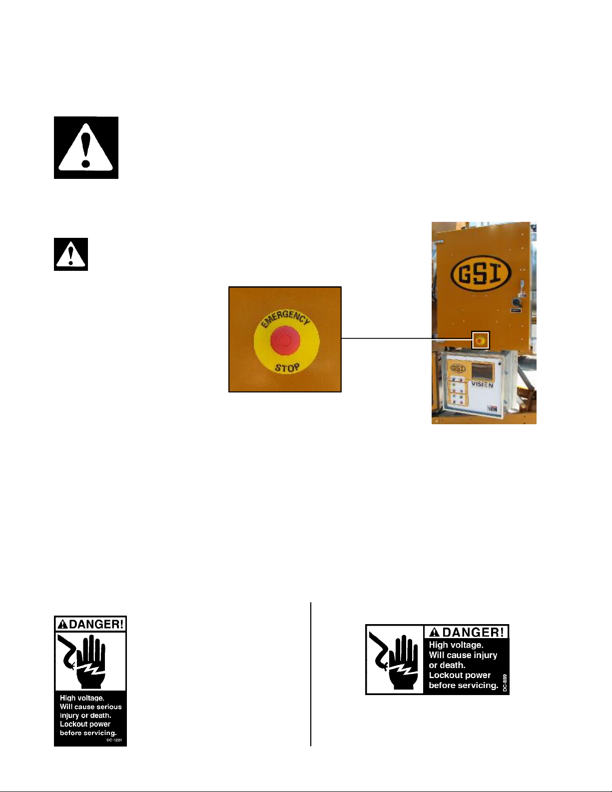
EMERGENCY STOP SWITCH
The emergency stop switch is located on the upper control box door. Pushing the emergency stop switch will interrupt the control
power and stop all dryer functions.
WARNING: Pushing the emergency stop switch does not
interrupt the main power to the upper control box panel.
SAFETY DECALS
The GSI Group, Inc. recommends contacting your local power company, and having a representative survey your installation so the
wiring is compatible with their system, and adequate power is supplied to your unit. Safety decals should be read and understood by
all people in the grain handling area.
If a decal is damaged or is missing contact:
The GSI Group, Inc.
1004 E. Illinois St.
Assumption, IL 62510
217-226-4421
A free replacement will be sent to you.
Decal: DC-1224
Decal DC-1224 is located in two places on
the fan/heater control box. One on the lid and one
on the front of the fan heater control box. Another location for this decal is inside the upper
control box for the dryer.
Decal: DC-889
Decal DC-889 has two locations. One inside the fan/heater
control box and another on the dryer upper control box door
next to the main power disconnect.
PNEG-1459 L Series Operators
5
Page 6
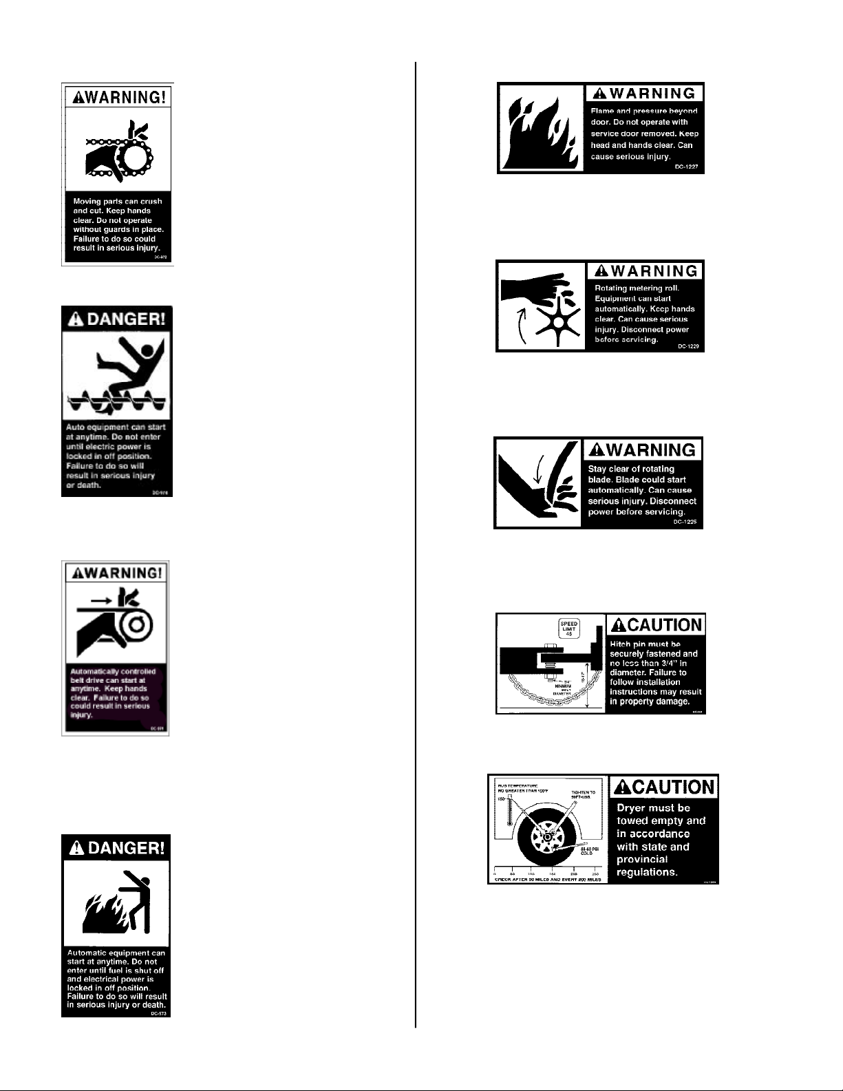
Decal: DC-972
SAFETY
Decal DC-972 is located on the bottom
auger belt guard and the front bearing plate
(which is visible when then bottom auger belt
guard is removed). An alternate location
would be at the rear of the dryer for portable
dryers equipped with the Front Discharge
Option.
Decal: DC-1227
Decal DC-1227 is located on the fan/heater access door.
Decal: DC-1229
Decal: DC-974
Decal: DC-971
Decal DC-974 has several different locations. Two are located on the front end
panel below the fan/heater. Two are located
on the rear end panel below the rear access
door. Two are located on the auger discharge
box (one on the outside top and one on the
inside of the flapper lid next to the discharge
mercury switch). One more of these decals
is located inside the plenum on the rear plenum closure door just inside the rear access
door.
Decal DC-971 is located on the bottom
auger belt guard and the front bearing plate
(which is visible when then bottom auger belt
guard is removed). An alternate location
would be at the rear of the dryer for portable
dryers equipped with the Front Discharge
Option.
Another location for decal DC-971 is
the top auger belt guard (one on the belt guard
cover and one inside on the belt guard body
visible when the belt guard cover is remove).
Decal DC-1229 is located on each of the meter roll access
doors.
Decal: DC-1225
Decal DC-1225 is located on the fan/heater access door.
Decal: DC-388
Decal DC-388 is located on the hitch tongue.
Decal: DC-1249
Decal: DC-973
6
Decal DC-973 is located on the rear ple-
num access door (inside and outside).
Decal DC-1249 is located on the hitch tongue.
PNEG-1459 L Series Operators
Page 7
SPECIFICATIONS
Models 3020L, 4026L, 6034L,
7534L, and 1038L for Dry & Cool:
Designed for drying in the top 2/3 of
the grain column and vacuum cooling
in the lower 1/3 of the grain column,
thus reclaiming the heat in the grain
to preheat the drying air.
Field Conversion: Converter packages are available to permit conversion from Full Heat to Dry & Cool
(pressure or vacuum cooling).
GRAIN COLUMNS: Two 14" galvanized steel grain columns. Solid column dividers every two feet. Grain
movement through columns is controlled by advanced electronic variable speed metering roll drive control.
AUGERS: Automatically controlled
top leveling auger. Bottom auger
unloads grain discharged from metering rolls. Heavy-duty construction.
MOISTURE CONTROL: Automatic
moisture control system uses control
computer to modulate meter roll
speed.
AUTOMATIC CONTROL: Automatic
control of loading, drying, cooling,
and discharge functions. Full safety
control system; automatic shutdown
on wet grain outage, grain Hi-Limit,
and discharge safety shutoff.
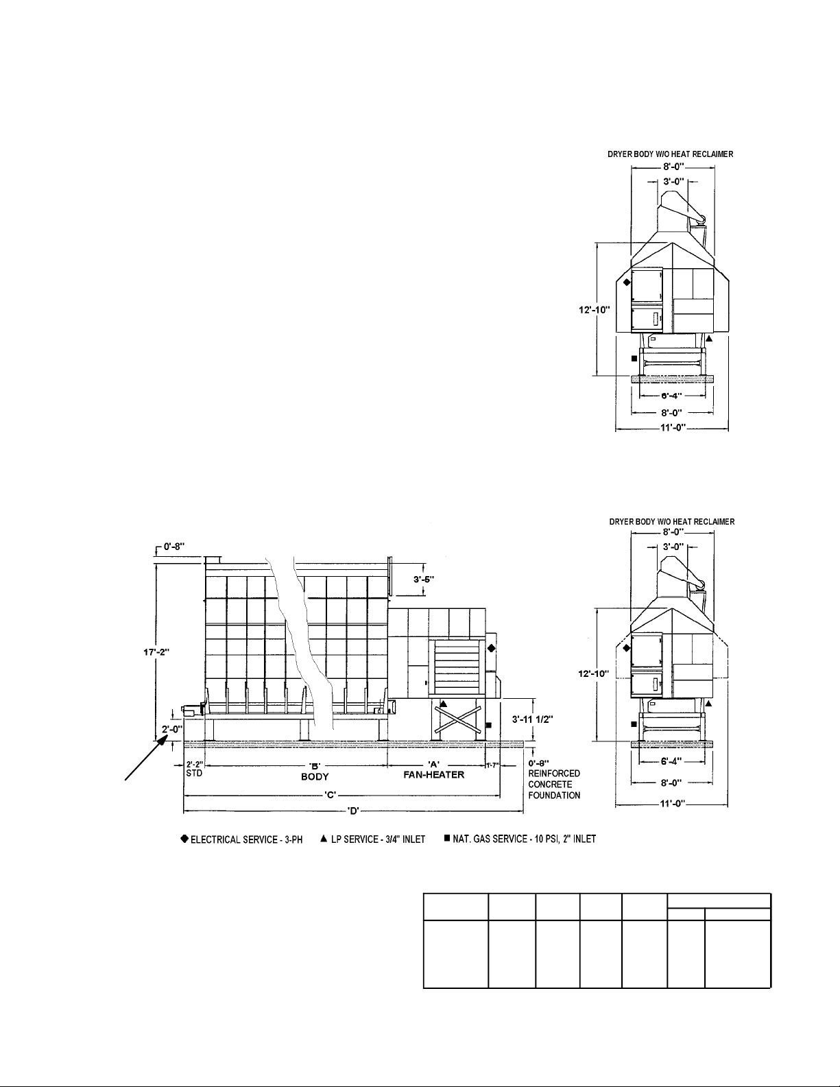
Section1: SPECIFICATIONS
SEE
NOTE 1
NOTE 1:
2’ LEG HEIGHT IS STANDARD.
OTHER HEIGHTS ARE AVAILABLE.
*
ALL MODELS:
DRYER BODY EXPANDS FROM
8’ TO 11’ WITH HEAT RECLAIMER
Fig. 1-1 Centrifugal dryer dimensions
PNEG-1459 L Series Operators
Model
3020L
4026L
6034L
7534L
1038L
‘A'
9'-6"
9'-6"
10'-11"
10'-11"
10'-11"
‘B'
20'-0"
26'-0"
34'-0"
34'-0"
38'-0"
‘C'
33'-3"
39'-3"
48'-8"
48'-8"
52'-8"
‘D'
37'-0"
43'-0"
52'-0"
52'-0"
56'-0"
Leg Pairs Required
Body Fan-Heater
32
42
52
52
52
7
Page 8
SPECIFICATIONS
SPECIFICATIONS CHART
TABLE 1-1 C-2100B SERIES SPECIFICATIONS
Basic Construction
Grain Column by Length
Grain Column Width
Total Holding Capacity
Wet Bin Capacity
Dry Section
Cool Section
Transport Dimensions:
Body Module
Length w/ Hitch
Width
Height
Fan Module
Length
Width
Height
Installed Dimensions
Grain Section Length
Fan-Heater Section
Length
Total Length
Width - w/ Heat
Reclaiming
Max. Width - w/o Heat
Reclaiming
Overall Height
Centrifugal Fan Type
Fan Motor
Burner - Max. Capacity
(Millions)
Top Auger
Capacity
Bottom Auger
2
Capacity
Meter Roll Drive
Electrical Load - Dryer
Only (3-PH)
Drying Capacity Shelled Corn
3
4
Dry & Cool 20-15%
Dry & Cool 25-15%
Full Heat 20-15%
Full Heat 25-15%
3020L
One module
with two zones
20 ft.
14 in.
595 bu.
135 bu.
307 bu.
153 bu.
29'-2"
8'-0"
12'-10"
11'-1"
8'-0"
8'-10"
20'
11'-1"
33'-3"
11'-0"
8'-0"
1
17'-2"
DIDW
30 HP
7 M Btu/Hr.
8", 7.5 HP
2800 BPH
8", 7.5 HP
1360 BPH
3/4 HP, SCR
117A @ 230V
59A @ 460V
595 BPH
350 BPH
945 BPH
550 BPH
4026L
One module
with two zones
26 ft.
14 in.
775 bu.
175 bu.
400 bu.
200 bu.
35'-2"
8'-0"
12'-10"
11'-1"
8'-0"
8'-10"
26'
11'-1"
39'-3"
11'-0"
8'-0"
1
17'-2"
DIDW
40 HP
9 M Btu/Hr.
8", 10 HP
2800 BPH
8", 10 HP
1770 BPH
3/4 HP, SCR
155A @ 230V
78A @ 460V
774 BPH
455 BPH
1220 BPH
720 BPH
6034L
One module
with two zones
34 ft.
14 in.
1010 bu.
229 bu.
521 bu.
260 bu.
43'-2"
8'-0"
12'-10"
12'-6"
8'-0"
8'-10"
34'
12'-6"
48'-9"
11'-0"
11'-0"
1
17'-2"
DIDW
60 HP
12 M Btu/Hr.
8", 10 HP
2800 BPH
8", 10 HP
2315 BPH
3/4 HP, SCR
205A @ 230V
103A @ 460V
1010 BPH
585 BPH
1610 BPH
940 BPH
7534L
One module
with two zones
34 ft.
14 in.
1010 bu.
229 bu.
521 bu.
260 bu.
43'-2"
8'-0"
12'-10"
12'-6"
8'-0"
8'-10"
34'
12'-6"
48'-9"
11'-0"
11'-0"
1
17'-2"
DIDW
75 HP
12 M Btu/Hr.
8", 10 HP
2800 BPH
8", 10 HP
2315 BPH
3/4 HP, SCR
240A @ 230V
120A @ 460V
1070 BPH
620 BPH
1680 BPH
980 BPH
1038L
One module
with two zones
38 ft.
14 in.
1129 bu.
256 bu.
582 bu.
291 bu.
47'-2"
8'-0"
12'-10"
12'-6"
8'-0"
8'-10"
38'
12'-6"
52'-9"
11'-0"
11'-0"
1
17'-2"
DIDW
100 HP
12 M Btu/Hr.
8", 15 HP
2800 BPH
8", 10 HP
2585 BPH
3/4 HP, SCR
310A @ 230V
155A @ 460V
1210 BPH
700 BPH
1900 BPH
1100 BPH
Dryer Specs
8
1.Overall height includes 24" high foundation supports, less 8" hopper.
2.Actual discharge rate is controlled by meter roll speed adjustment, at 5% to 100% of maximum rate.
3.Excludes auxiliary load and unload conveyor equipment.
4.Capacities listed are wet bushels at listed input moisture content and are estimates based on drying
principles, field results, and computer simulation. Variances may occur due to the grain's physiological
factors (kernel size, chemical composition, variety, maturity), excessive fines, adverse weather
conditions, etc.
PNEG-1459 L Series Operators
Page 9
Heater Switches
Fan Switches
Load Auger Switch
Unload Auger
Switch
Operator Light
Switch
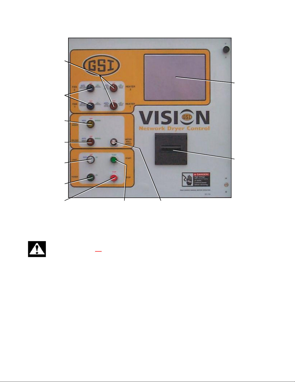
VISION CONTROL PANEL
Vision Control Panel Layout
Touch Screen
Moisture Manager
Printer (Optional)
Control Power Switch
Stop Switch
Start Switch Meter Roll Speed
CONTROL POWER SWITCH
The control power to energize the Vision Control System is turned on or off with this switch.
Note: This switch does not disconnect the power that is present at the breakers, contactors, transformer(s),
fuses or other electrical components found in the upper and lower control boxes. Turn the Main Disconnect
Handle to the OFF position prior to servicing any of the installed components.
FAN SWITCH
Each fan is turned on or off with this switch. The on position operates the fan continuously during staged batch and continuous
flow modes. The auto position operates the fan in staged batch during the dry and cool cycle but the fan will not operate during
the unload cycle. The switch will light up whenever the air pressure switch is sensing air pressure and the dryer is full of grain.
Note: The bottom fan on your dryer is always Fan 1.
HEATER SWITCH
Each burner is turned on or off with this switch. The auto position operates the burner in staged batch during the dry cycle only.
The on position will operate the burner only when the fan is running. The switch will light up only when the flame sensor
detects the flame.
Note: The bottom burner on your dryer is always Burner 1.
PNEG-1459 L Series Operators
9
Page 10

VISION CONTROL PANEL
LOAD AUGER SWITCH
This is used to select the operation of the fill auger. In both the auto and manual position the load auger will operate if the dryer
is low on grain and will automatically shut off when the dryer is full. In the auto position only the dryer will shut down after a
preset period of time set on the out of grain timer if grain flow is interrupted to the dryer. The load delay is disabled when the
load auger switch is in the manual position. The switch will light whenever the load auger is operating.
Note: If the load auxiliary controls are being used, this switch will also control the operation of the auxiliary equipment.
UNLOAD SWITCH
The unload switch turns the metering rolls and discharge auger on or off, and selects the operation of the metering rolls. In the
manual position the meter rolls will operate in 1 speed only. In the auto position the meter rolls switch to a multi-speed mode
for moisture control operation. The switch will light whenever the load auger is operating.
Note: If the unload auxiliary controls are being used, this switch will also control the operation of the auxiliary equipment.
OUTSIDE LIGHT SWITCH
The dryers outside service light is turned on or off here. It also may be set on auto, which turns the light on while the dryer is
running and off if a shutdown occurs.
START SWITCH
This switch starts and operates the dryer based on switch settings. If other switch settings are in the off position, individual
dryer components can be operated by turning the drying mode switch to continuous flow, pressing the dryer power run button
and then turning on the desired dryer component.
STOP SWITCH
This switch stops all dryer functions. If an automatic dryer shutdown occurs, first determine and correct the cause of the
shutdown. Then, press the dryer power stop button to reset the dryer before restarting.
10
PNEG-1459 L Series Operators
Page 11
VISION TOUCH SCREEN DISPLAY
THIS SECTION SHOULD BE READ FIRST TO FAMILIARIZE YOURSELF WITH THE VISION CONTROL
COMPUTER. THE DRYER OPERATION SECTION OF THIS MANUAL WILL REFER TO INSTRUCTIONS IN
THIS SECTION.
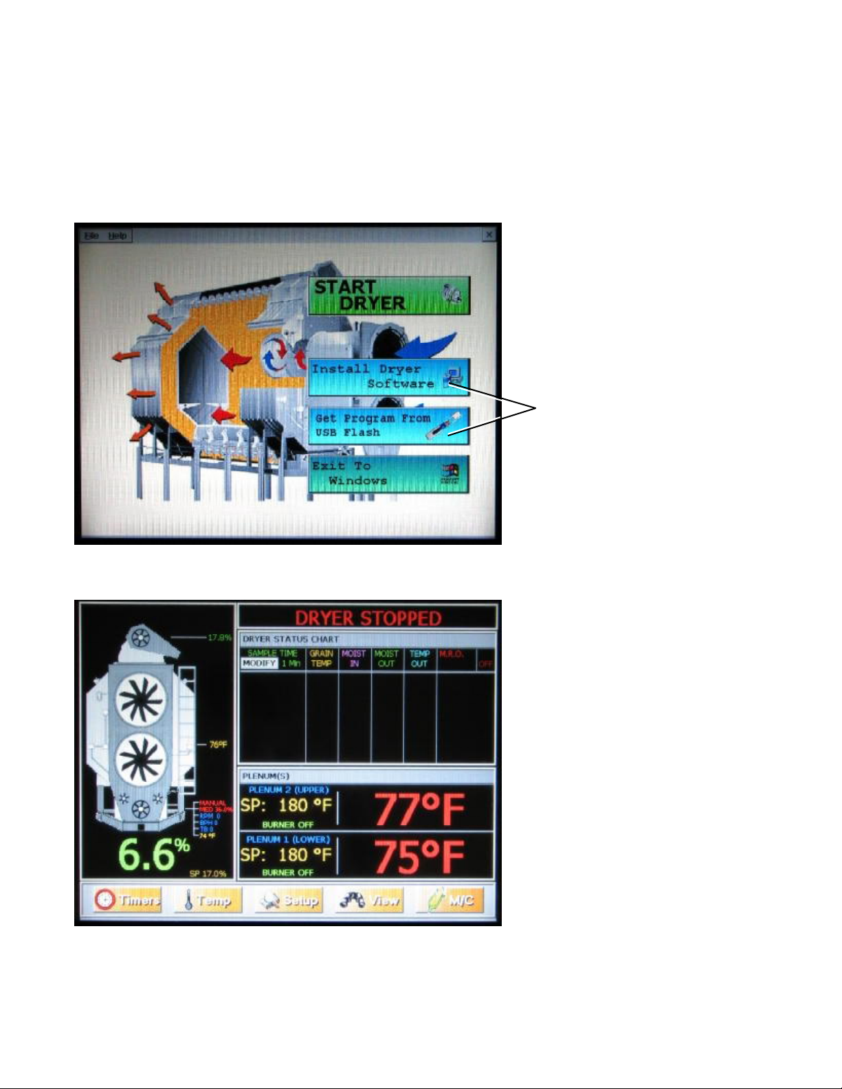
BOOT SCREEN
With the Power Switch in the on position, pushing the Start Switch will start the Vision computer. The first screen to appear will
be the boot screen (see image above). Notice that there are three “buttons” on the boot screen. The Update / Change Program
and Look For New Program On Flash Card buttons are only used for program updates that may be released at a later date.
Touching the Start Dryer button will display the Default Operation Screen.
These two buttons are used
to update software.
(See PNEG-1506 Vision
Programming Manual)
DEFAULT OPERATION SCREEN
As you can see the Operation Screen is divided
into five sections.
1.) Dryer operation animation: Located on
the left side of the Operation Screen the
operation animation shows the status of the fan/
heaters, load and unload augers and meter rolls.
It will also display the grain temp., moisture
content, M/C setpoint, and bushel counter.
2.) Dryer Status: Located at the very top of
the right side of the Operation Screen the Dryer
Status will tell you if the dryer is stopped,
started, loading, or unloading.
3.) Dryer Status Chart: Located directly
below Dryer Status. This chart will show the
grain temperature, moisture in/out, temperature
out and Meter Roll Output (M.R.O.) over a
period of time.
4.) Plenum(s): Located directly below Dryer
Status Chart. This will show the plenum temperature set point (SP), actual plenum temperature and burner status.
5.) Setup Buttons: Located across the bottom of the Operation Screen. By touching these buttons the timers, temperature set
points, dryer model and moisture control can be set up.
PNEG-1459 L Series Operators
11
Page 12
VISION TOUCH SCREEN DISPLAY
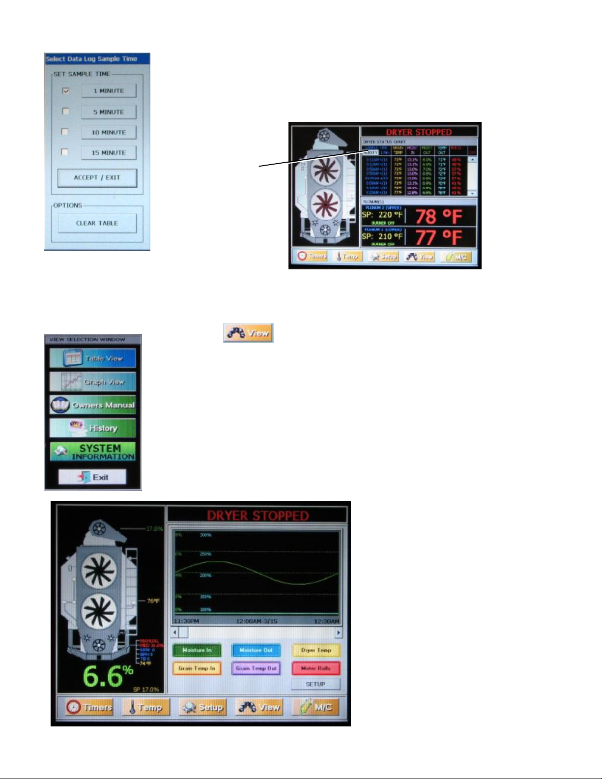
SELECT DATA LOG SAMPLE TIME
Notice the Modify button in the upper left hand side of the Dryer Status Chart. By touching this
button the sample time can be changed from 1 minute to 5, 10 or 15 minutes. Select the desired
sample time and touch Accept/Exit button to exit. Also notice that the chart can be cleared by
selecting the Clear Table button at the bottom.
Modify button
OPTIONAL OPERATION SCREEN
An optional Operation Screen can be selected that shows a graph instead of the chart view.
Touching thebutton at the bottom of the display will bring up the View Selection Window. Notice that you have four selections to choose from.
1.) Table View: This is the Default Operation Screen view (described on previous page).
2.) Graph View: This is the Optional Operation Screen view (shown below).
3.) Owners Manual: This option is described in greater detail on page 16.
4.) History: This option is described in greater detail on page 16.
5.) System Information: Touching this button will display the current software version your dryer
is running, and the time and date.
Touch the Graph View button then touch the
Exit button. The Optional Operation Screen
will appear. Notice that the Dryer Status Chart
and the Plenum(s) sections have been replaced
by the graph view (see image below). You can
choose what the graph will display by touching
any of the colored buttons under the graph (i.e.
Moisture In, Moisture Out, Dryer Temperature,
Grain Temperature In, Grain Temperature Out
and Meter Rolls).
Touching these buttons once will display them
on the graph, and touching them again will
remove them from the graph.
12
The Setup button will bring up the Graph
Setup Window and allow you to choose the
length of time (1, 2, 4 or 8 hours) for the
horizontal scale.
PNEG-1459 L Series Operators
Page 13
VISION TOUCH SCREEN DISPLAY
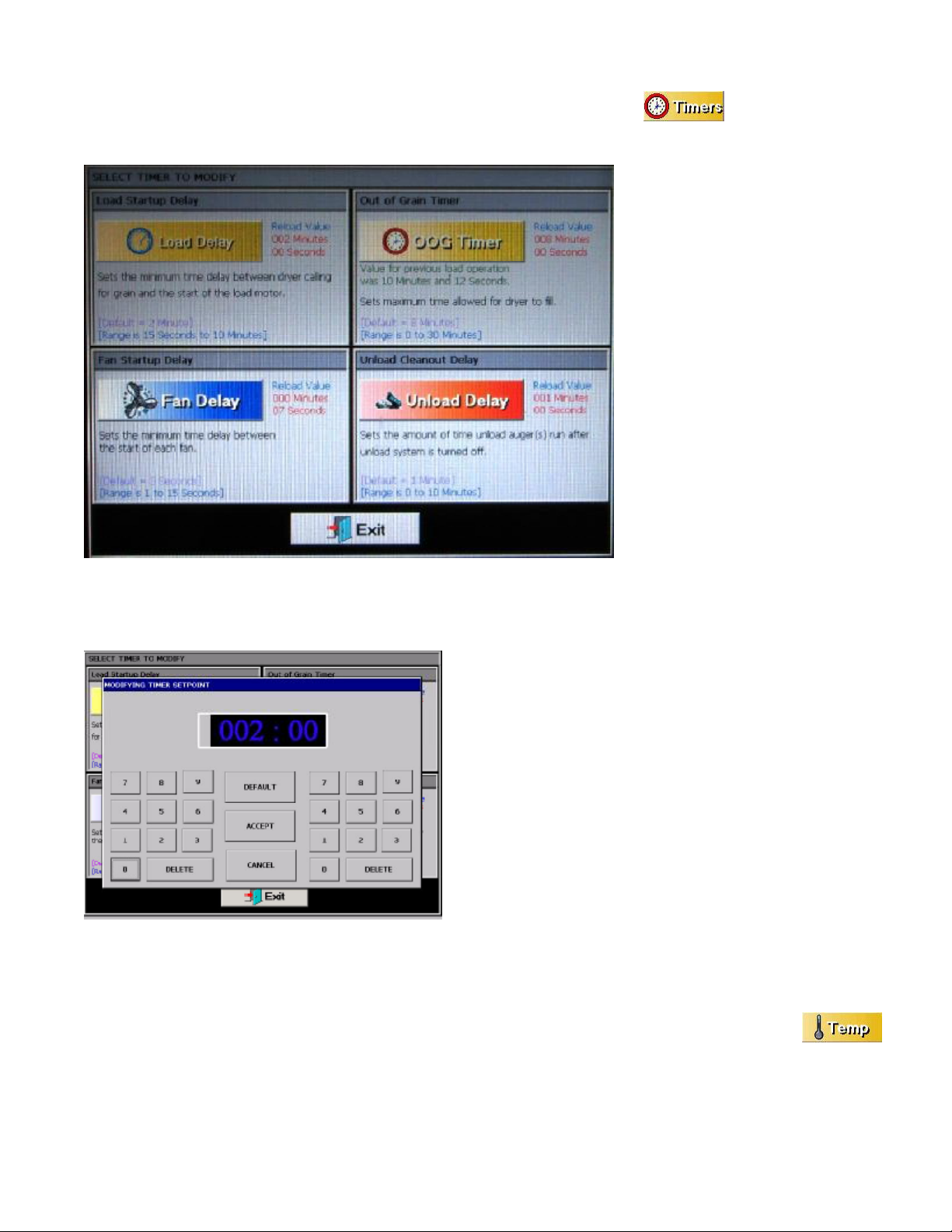
SETTING THE TIMERS
Setting the timers for the dryer is a simple procedure. To set the timers touch the buttonat the bottom of
Operation Screen. A new screen will appear called the Select Timers to Modify screen (shown on the left). As you can see there
are 4 timers that you can modify:
1.) Load Delay: (Default setting - 2
minutes)This delay is used to delay the
starting of the load auger when the
dryer is unloading to prevent the load
auger from cycling to often. The load
delay is active only when the load auger
switch in the auto position.
2.) Out of Grain (OOG) Timer:
(Default setting - 8 minutes)The OOG
timer should be set to the maximum
time it takes for your dryer to refill
during continuous or batch drying
modes. Note that the computer will
display the time required to fill your
dryer on the previous load operation to
aid you in setting an accurate time. If
the dryer runs out of grain while the
load auger switch is in the auto position, the OOG timer automatically shuts
off the dryer after the period of time
preset on the timer.
3.) Fan Delay: (Default setting - 3 seconds) The Fan Sequence Delay timer controls the amount of time between each fan startup to reduce the dryer start-up amperage.
4.) Unload Delay: (Default setting - 1 minute)The Unload Delay
timer is used to control the amount of time the unload auger runs
after the metering rolls stop to allow the unload auger to clean itself
out.
To setup a timer touch the button of the timer you wish to modify.
The Modify Timer Setpoint screen will then be displayed (see
image at left). Note that there are two number pads on this modify
screen. The left number pad is used to modify the minutes and the
right number pad will modify the seconds. Touching the Default
button will automatically set the timer to the default setpoint for
that timer. The Accept button will save the timer setpoint displayed
in the time display. Touching Cancel will exit the Modify Timer
Setpoint screen without saving any changes and the timer will stay
at the currently saved setpoint.
Once you have the timer setpoints set touching the Exit button at the bottom of the Modify Timer Setpoint screen will return you
to the Operation Screen.
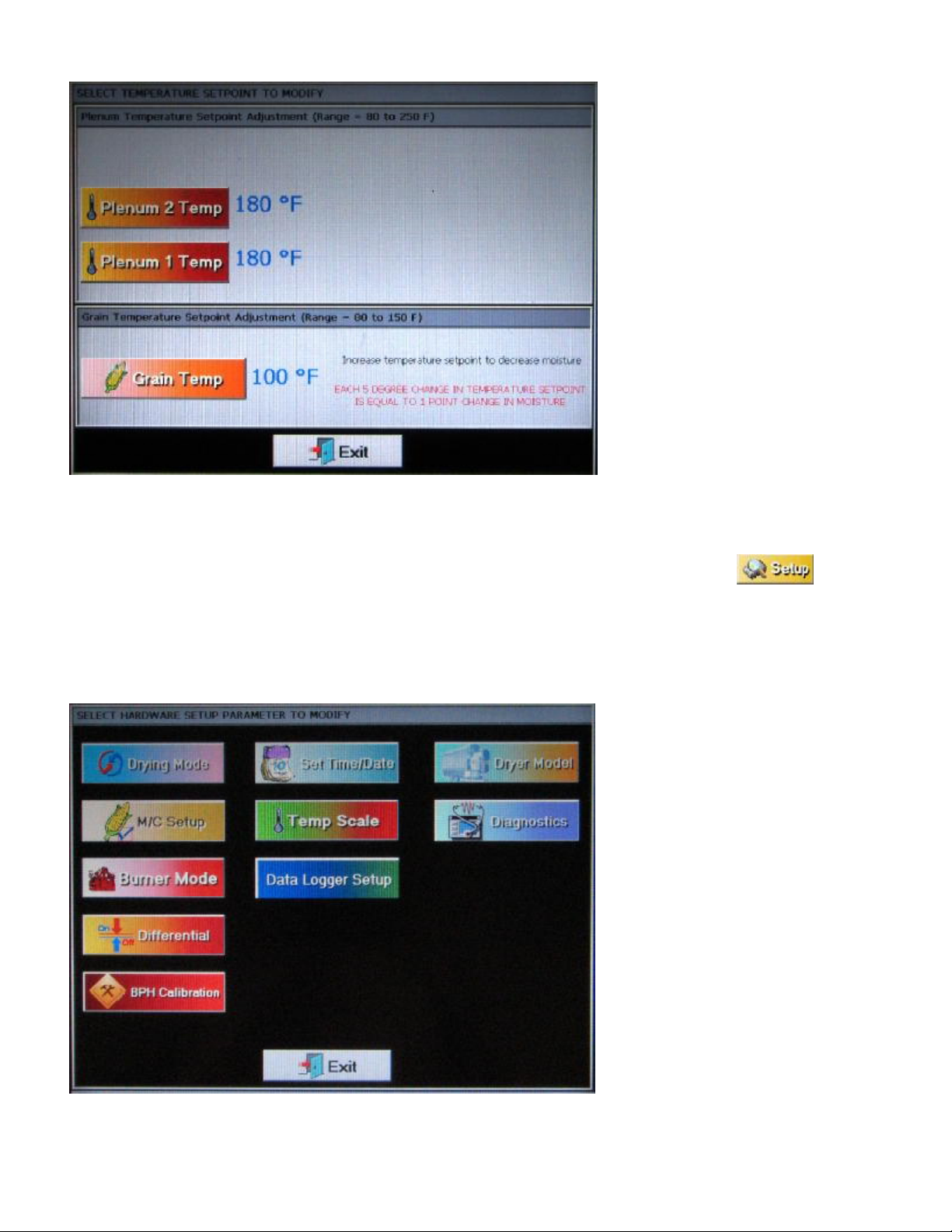
SETTING THE TEMPERATURES
Setting the temperature setpoints for the dryer is a simple procedure. To adjust the temperture setpoints touch the
button at the bottom of Operation Screen. A new screen will appear called the Select Temperature Setpoint to Modify screen
(shown at the top of the next page). As you can see you modify the setpoint for each of the plenums by touching the desired
plenum button.
NOTE: Plenum one is the bottom plenum and plenum two is the top plenum for a two fan dryer. Use plenum one for a single
fan dryer.
PNEG-1459 L Series Operators
13
Page 14
VISION TOUCH SCREEN DISPLAY
The plenum temperature setpoint range
is 80oF - 250oF, and the current temperature setpoint for each plenum is displayed next to the corresponding
plenum button.
The grain temperature setpoint range is
80oF - 150oF, and the current temperature setpoint for the grain temperature is
displayed next to the Grain Temp.
button.
Modifying a temperature setpoint is
much like setting a timer described on
the previous page. Touch the desired
button of the setpoint you wish to
change. The Modify Temperature
Setpoint screen will appear. Enter the
desired temperature using the displayed
number pad then touch the Accept
button. Touching the Exit button at the
bottom of the Select Temperature Setpoint to Modify screen will return you to the Operators Screen.
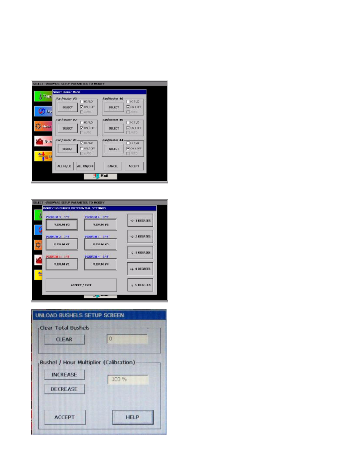
THE SETUP SCREEN
The Setup Screen will allow you to setup other parameters of your dryer. To use the Setup Screen touch thebutton. The Select Hardware Setup Parameter To Modify screen will now be displayed. As you can see there several different
parameters that can be modified on this screen:
1.) Drying Mode: Touching the Drying Mode button will display the Select Drying Mode window. Touch the desired drying
mode button (Continuous Flow or Staged Batch). A check mark is displayed next to the currently selected drying mode.
2.) Set Time/Date: Touching the Set
Time/Date button will display the Set
Time/Date window. Use the up and
down buttons to change each of the
parameters for date and time. Touch
Accept / Exit to save settings and return
to the Select Hardware Parameter To
Modify screen.
3.) Dryer Model: Touching the Dryer
Model button will display the Dryer
Hardware Setup window. In order for
your dryer operate properly the following items must be entered correctly:
a) Number Fan/Heaters
b) Load System
c) Dryer Length (ft.)
d) Number Modules
e) Fuel
Touch the select button until a check
mark appears next to the parameter
corresponding to your dryer model.
4.) M/C Setup: The M/C Setup operations are described in greater detail in the dryer operation section of this manual.
14
PNEG-1459 L Series Operators
Page 15
VISION TOUCH SCREEN DISPLAY
5.) Temp Scale: Touch the Temp. Scale button to choose either English units or SI units temperature scales. Depending what
temperature scale you now operating in touching this button will display a popup window asking if you want to switch to SI
(Celsius, metric tons, etc..) or English units (Fahrenheit, bushels, etc..)
6.) Diagnostics: The Diagnostics operations are described in greater detail in the service section of this manual.
7.) Burner Mode: Touching the Burner Mode button will display
the Select Burner Mode screen (see image at left).
NOTE: The bottom fan heater on a two fan dryer is always fan
heater one.
The Select Burner Mode screen will allow the operator to select
the type of burner operation for each burner. In the HI/LO mode
the burner will switch from high heat to low heat when the plenum
temperature setpoint has been reached. In the ON/OFF mode the
burner will shut off when the upper temperature setpoint has been
reached. To select either the HI/LO or ON/OFF modes touch the
Select button for the fan heater you wish to change. Touching the
All HI/LO button will set all burners to HI/LO mode and touching
All ON/OFF will set all burners to ON/OFF mode. Touch the
Accept button to save any changes and return to the setup screen
or touch Cancel to return to setup screen without saving any
changes to the burner modes.
8.) Differential: Touching the Differential button will display the
Modify Burner Differential Settings screen (see image at left).
Adjusting the burner differential settings allows the operator to
keep the plenum temperature within a certain range. For example:
If you have the temperature setpoint at 180 degrees and you select
+/- 3 degrees as the burner differential, then the burner will switch
to low heat at 183 degrees and back to high heat at 177 degrees.
To modify a burner differential setting first touch the plenum
button you wish to modify, then select one of the five differential
setting button on the right side of the Modify Burner Differential
Settings screen. Touch the Accept / Exit button to save settings
and return to the Select Hardware Setup Parameter To Modify
screen.
9.) BHP Calibration: Touching the BHP Calibration button will
display the Unload Bushels Setup screen (see image at left). As
you can see the bushel counter can be cleared by touching the
CLEAR button. However if the bushel counter is out of calibration
it can be calibrated by touching the INCREASE and DECREASE
buttons.
Example: If you ran 1000 bushels through the dryer but the
bushel counter on the dryer reads 900 bushels then touch the
DECREASE button until the calibration reads 90%, or if you ran a
1000 bushels and the counter reads 1100 bushels then touch the
INCREASE button until the calibration reads 110%.
PNEG-1459 L Series Operators
When you are finished with the calibration or clearing the bushel
counter touch the ACCEPT button to return to the Hardware Setup
Parameter screen.
15
Page 16
VISION TOUCH SCREEN DISPLAY
10.) Meter Roll Reverse: Touch the Meter Roll Reverse button to reverse the metering rolls. Reversing the metering rolls aids
in cleaning out the fine material that builds up over the course of the drying season. Just touching this button will toggle
between normal meter roll operation and reversed meter roll operation.
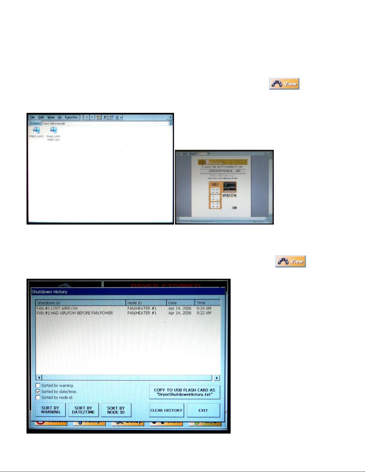
VIEWING THE OWNERS MANUALS ON THE DISPLAY SCREEN
The operators and parts manuals can be viewed on the display screen. To view a manual touch thebutton.
When the View Selection Window appears touch the Owners Manual button. A new display will appear called an explorer
window (shown below). The explorer window will show the manuals that are stored in the computer memory. In this case they
are PNEG-1403 (2 Fan Vision Parts), and PNEG-1456 (1 & 2
Fan Vision Operators). To select a manual to view you must
“double tap” the desired manual icon. Much like double
clicking a mouse on your computer. Once selected it may take
a few seconds for the manual to be displayed. Once the manual
is displayed use the scroll bars on the right to scroll through the
pages of the manual.
To exit the manual
and return to the
Operation Screen
touch the X button in
the upper right corner
of the screen.
VIEWING THE DRYER SHUTDOWN HISTORY
The dryer will keep track of all safety shutdown warnings. To view the Shutdown History touch thebutton.
When the View Selection Window appears touch the History button. A new window called Shutdown History will appear. A list
of all shutdown warnings are listed.
This list can be sorted by:
1.) Warning
2.) Date/Time
3.) Node
by touching any of the three sort by
buttons.
The whole list can be copied to a USB
flash drive and transferred to a personal
computer as a text file by touching the
Copy To USB Flash Card button.
The list can also be cleared to start a
new list by touching the Clear History
button.
To return to the Operators Screen touch
the Exit button.
16
PNEG-1459 L Series Operators
Page 17
TEST FIRING
DRYER PRESEASON CHECKS
This section gives a series of checks to be carried out on the dryer before starting for the first time in the drying
season. If any of the checks fail to produce the stated result, you should consult your dealer.
YOU SHOULD NOT ATTEMPT TO USE THE DRYER UNLESS ALL THE PRE-START CHECKS HAVE
BEEN SUCCESSFULLY COMPLETED.
BEFORE ATTEMPTING TO
OPERATE THE DRYER MAKE SURE ALL SAFETY SHIELDS ARE IN PLACE, ALL BOT-
TOM CLEAN OUT AND REAR ACCESS DOORS ARE CLOSED AND ALL PERSONNEL ARE
CLEAR OF THE DRYER
INSPECT THE METERING ROLLS
Open all metering roll access doors and inspect each compartment for any bolts, nuts or other foreign material, that may
cause possible jamming of the metering rolls.
CHECK CONTROL PANEL SWITCHES
Before applying electrical power to the dryer, be sure that all switches on the dryer control panel are in the OFF position.
ELECTRICAL POWER
Turn on the electrical power supply to the dryer, set all circuit breakers to on, including the safety disconnect handle mounted
on front of the dryer power panel.
CONTROL POWER SWITCH
Turn the control power switch to on. At this point the controller will lock out all other dryer functions. Once the Boot
Screen appears (see page 12), touch the START DRYER button and the dryer will perform a safety circuit check. If a fault is
found, the cause will be displayed on the Main Screen. If all are found safe, the controller will supply power to the electronic
fuel shut-off valve (Maxon), if so equipped, and the start switch will light up, indicating that the dryer is ready to be started.
START SWITCH
Push the dryer start switch, and all the selector switches on the control panel will be activated.
FUEL CHECK
If using LP gas, make sure the tank has plenty of fuel and that the tank does not have a regulator mounted on the liquid line.
Slowly open the main fuel supply valve at the tank. Then, open the electronic shut off valve (Maxon valve), if so equipped, or
open the manual shut off valve on the dryer to allow fuel flow to the dryer.
If using natural gas, make sure an adequate supply is available. Turn on the valve along the supply line. Then, open the electronic shut off valve (Maxon valve). Inspect all gas lines and connections for possible leaks.
Any gas leaks must be fixed immediately!
LOAD AUGER
With the grain supply shut off, quickly bump the load auger switch to manual, and see if the load auger rotates clockwise as
viewed from the drive end, or counterclockwise if the dryer is a front load model. If the wet grain supply auxiliary is wired to
the dryer it should also rotate in the correct direction at this time.
Turn the load auger switch to the auto position. The top auger and wet grain supply auxiliary should run for eight (8) min-
PNEG-1459 L Series Operators
17
Page 18

TEST FIRING
utes, and then the dryer will shutdown leaving the safety shutdown message (out of grain warning) displayed. Press the dryer
power stop button to reset the panel, then press the start button.
UNLOAD AUTO OPERATION
To check auto operation place the unload switch in the auto setting. Turn the meter roll dial until the meter rolls start rotating. The bottom auger should rotate counterclockwise as viewed from the drive end. The meter roll drive motor should rotate clockwise as viewed from the drive end of the gear box. If the dry grain take away auxiliary is wired to the dryer, it
should start and rotate in the proper direction.
UNLOAD MANUAL OPERATION
To check manual operation move the unload switch to the manual position. Turn the meter roll dial until the meter rolls start
rotating. The bottom auger should rotate counterclockwise as viewed from the drive end. The meter roll drive motor should
rotate clockwise as viewed from the drive end of the gear box. If the dry grain take away auxiliary is wired to the dryer, it
should start and rotate in the proper direction.
METER ROLL OPERATION
To check the meter roll operation turn the knob clockwise, and the meter roll speed should increase. Turning the knob counterclockwise will decrease the speed. When the meter rolls are set to maximum (1000) the meter roll speed should be 17.5
RPM for 8” (20 cm) discharge augers. Make sure the drive chain tension is properly adjusted and all sections of the meter
rolls rotate. Turn the unload switch off after these checks are complete. The bottom auger will continue to run for 60 seconds (default clean out delay setting) after the switch is turned off to allow for clean out.
Note: Due to the nature of the DC drive motor used on the meter rolls, it is possible for the brushes inside the motor
to become corroded if the dryer has not been operated for several months. This will cause the meter rolls not to function. To fix this problem, use a rubber mallet or a piece of wood to tap the DC drive motor. The shock is usually all
the motor needs to start working again. You should not have any more problems with this during the rest of your
drying season.
FAN SWITCHES
Momentarily turn each fan switch to on and observe the fan rotation. The fan should run counterclockwise. Sometimes on
three phase models all motors will run backwards. They can easily be reversed by interchanging two of the three power supply wires. All power should be switched and locked off before attempting to reverse the connections. Reverse the two outside wires, L1 and L3, and leave the middle one in the same position.
BURNER SAFETY
To check the burner safety function, first make sure the main gas valve is off. Turn the fan switch on and allow the fan to
start. Then, turn the heater switch on for that fan. The dryer will shut down after 20 seconds. The safety message, “Ignition
Failure Fan #” will appear. Reset the dryer and repeat for the other fan/heater(s).
BURNER TEST FIRE
To perform this test the dryer will need to be full of grain or the air switch need to be disabled. Test fire each burner by starting the fan. Turn on the fuel supply then, turn the burner switch to on and the burner should ignite after a short purge delay
of approximately 10 seconds. Gas pressure should be shown on the gauge. At this time adjust the plenum set point to 200°F
(93°C), causing the burner to operate on hi-fire. Observe the gas pressure on the gauge, and lower the plenum set point until
it causes the burner to cycle into lo-fire. When the plenum temperature set point is met, the gas pressure should show a noticeable drop, indicating that the cycle solenoid is closed and the burner is being supplied with less gas through the cycle solenoid bypass port. At this time set the hi-fire and lo-fire pressure settings. Use the pressure regulator (for LP models) or the
supply line ball valve (for nat. gas models) for hi-fire and the ball valve on the lo-fire bypass line for lo-fire (see images on page
39 for help). The computer should cycle the burners between high and low, approximately 1 to 3 times per minute.
Only use pressure required to obtain desired temperature.
18
PNEG-1459 L Series Operators
Page 19

TEST FIRING
Approximate settings should be:
LP GasHi-Fire 6-15 PSI (41-102 kPa)
Lo-Fire 2-6 PSI (14-41 kPa)
Natural GasHi-Fire 6-10 PSI (41-69 kPa)
Lo-Fire 1-3 PSI (7-20 kPa)
If the burner remains on hi-fire and does not cycle, increase the regulator setting on the propane models, or the supply valve
on the natural gas models in order to reach the plenum set point. If the burner remains in lo-fire and does not cycle, slightly
decease gas pressure with the lo-fire adjustment screw on the cycle solenoid. If the gas pressure is decreased too much a
popping or fluttering sound will be heard. This popping and fluttering should not be allowed to continue or damage to the
burner will occur. Also, anytime the high pressure side is adjusted, the low pressure side needs to be checked. Repeat the test
for each fan/heater unit.
Note: If the flame sensor fails to detect a burner flame or is defective and signals a dryer shutdown all systems will shut
down except for the blower motor. This is to prevent wear on the blower motor curcuit from repeated start ups and shut downs.
DRYER SHUTDOWN
To shut down the dryer,
1. Close the fuel supply valve at the tank or valve along the fuel line.
2. If the burner is operating, let the dryer run out of fuel, and it will shut down automatically due to loss of flame.
3. Close the fuel valve at the dryer, and press the dryer power stop button.
4. Turn off the control power.
5. Turn off the safety disconnect handle on the front of the power box, and turn off the main power to the dryer.
EMERGENCY
In case of emergency push the dryer stop button or the emergency stop button. This will interrupt power to the control panel
and the fan, burner and all augers will stop immediately.
PNEG-1459 L Series Operators
19
Page 20

DRYER OPERATION - START-UP
DRYER START-UP AND OPERATION
FULL HEAT DRYING
Full Heat Operation
With this type of drying, the grain is discharged hot, with no cooling. Drying capacity is substantially higher with FULL HEAT
than the DRY AND COOL process.
Final Moisture
From 1 to 3% apparent moisture is usually removed in the cooling process, so hot shelled corn is removed from the dryer at
about 17% moisture if the final desired moisture content is 15%.
DRYING TEMPERATURES
Shelled Corn
For shelled corn with an initial moisture content of 25-30%, the recommended maximum drying temperature is 220-240o F (104116o C) for the top fan and 170-190o F (77-88o C) for the bottom fan.
Small Grain
For drying small grain (wheat, oats, milo), 150o F (66o C) is suggested.
Soybeans
Drying temperatures are critical in drying rice and soybeans. A temperature of 130o F (54o C) is recommended to keep grain
temperature low.
Drying Efficiency
The general rule for obtaining the highest drying efficiency is to use the highest possible drying temperatures which will not
adversely affect grain quality.
DRYER SHUTDOWN
Cooling Hot Grain
If the dryer is to be shut down while filled with grain, it is recommended that hot grain be cooled for 10 to 15 minutes, especially in cold weather, to prevent water vapor condensation and possible freezing of such condensate following shut down.
INITIAL SETUP PARAMETERS
Turn the control power switch to on. When the Boot Screen appears touch the START DRYER button. The computer will run a
quick check of the system network after which the Operation Screen will appear.
TIMER AND DELAY SETTINGS
Setting the timers for the Vision Dryer is a simple procedure. To set the timers touchthe button at the bottom
of Operation Screen. A new screen will appear called the Select Timers to Modify screen (see page 13 for instructions on how
to set the timer and delays).
SETTING THE TEMPERATURES
Setting the temperature setpoints for the dryer is a simple procedure. To adjust the temperture setpoints touch the
button at the bottom of Operation Screen. A new screen will appear called the Select Temperature Setpoint to Modify screen
(see page 13 for instructions on how to set the temperatures).
START-UP
Start-up Procedure
At the beginning of each harvest and before filling the dryer with grain make sure to inspect the dryer for rodent damage, proper
belt and chain tension and missing or damaged safety shields. Test operate the dryer using the pre start check procedures.
1.Before attempting to operate the dryer make sure that all safety shields are in place, all plenum bottom closure panel doors
are closed, all rear access doors are closed and all personnel are clear of the grain dryer and grain handling machinery.
2.Turn all selector switches on the control panel to the off position.
20
PNEG-1459 L Series Operators
Page 21

DRYER OPERATION - START-UP
3.Turn on the electrical power supply to the dryer, and move the safety disconnect handle mounted on the dryer’s upper
power box to on.
4.Turn the control power switch to on. The switch will light up. The control computer will boot up. At this point the controller will lock out all other dryer functions. Once the boot screen appears, touch the Start Dryer button and the dryer will perform
its safety circuit checks. If a fault is found the cause will be displayed on the Display screen (touch screen). If all safeties do not
detect a problem the controller will allow the electronic fuel shutoff valve (Maxon) to be manually opened, if so equipped. The
dryer is ready to be started.
5.Move the load auger switch to manual, and push the dryer start switch. The top auger will immediately start, and the load
auger switch will light up. If additional loading equipment is wired to the dryer it will also start immediately.
6.When the dryer is full of grain the top auger will stop automatically, and any auxiliary loading equipment wired to the dryer
will also stop.
The dryer is now ready to begin drying grain. There are three moisture control options to use in the dryer operation:
1.) Dryer Operation - Basic Moisture Control (page 22)
2.) Dryer Operation - Intermediate Moisture Control (page 26)
3.) Dryer Operation - Advanced Moisture Control (page 30)
PNEG-1459 L Series Operators
21
Page 22

DRYER OPERATION - BASIC MOISTURE CONTROL
CONTINUOUS FLOW DRYING MODE USING BASIC MOISTURE CONTROL
Full Heat-Continuous Flow Operation
This section begins with step 7 and it is assumed that steps 1 through 6 in the start-up procedure described on page 20 & 21
have been completed.
7.Touch the SETUP button at the bottom of the Dryer Operation screen. Once the Hardware Parameter screen is displayed
touch the DRYING MODE button. When the Select Drying Mode window appears touch the CONTINUOUS FLOW button to
select continuous flow drying mode. Then touch the EXIT button and return to the Hardware Parameter screen. Touch the M/C
SETUP button. When the Moisture Control Selection window appears select the BASIC : REGULATION OF GRAIN TEMPERATURE : 2 MR SETPOINTS moisture control option. Touch the EXIT button and return to the Dryer Operation screen.
8.Make sure the UNLOAD switch is OFF.
9.Open the main fuel supply valve on the tank if using LP gas, or the valve in the fuel supply line if using natural gas. Turn on
the Maxon electric shut off valve, if so equipped, or open the manual shut off valve to allow fuel flow to the dryer.
10. The dryer should already be filled with grain. Turn the LOAD AUGER switch to the AUTO position. In both the auto and
manual positions, the dryer grain level switch will automatically keep the dryer full of grain. In the auto position the dryer will
shut down after a preset time period using the out of grain timer.
11.Turn each FAN switch to ON. The fan will start, and the switch will light up when air pressure is detected.
12.Start each burner by turning the HEATER switch to ON. After purging for approximately 10 seconds the burner will fire,
and the heater switch will light up. This indicates that the flame sensing circuit is sensing burner flame. For information concerning burner adjustment see the Dryer pre start checks section of this manual. Set the plenum temperature setpoints to 180 oF.
13.Look in the Drying Charts section starting on page 36 for the FULL HEAT chart settings that correspond to your model of
dryer. You will see the settings for (Initial Moisture) (Moisture Removed) (Approx. Dry Time) (1 Speed) (2 Speed Low) (2
Speed High) pick the line that has your initial starting moisture. These are the settings we will be referring to during this start up
procedure.
14.Run the fan(s) and heater(s) for about 10% longer than the (APPROX. DRYING TIME) required for the moisture you are
trying to dry.
15.Take the remaining number of burners to be started, divide that into the total drying time required, working up, start each
burner that many minutes apart. Run them about 10% longer than the (APPROX. DRYING TIME) total required for the
moisture you are trying to dry.
16.Example: 10% removal would be about 54 minutes, 15% removal would be about 76 minutes and 20% removal would be
about 100 minutes. Add 10 minutes to insure that the grain is dry.
17.After the time in step 14 turn the UNLOAD AUGER switch to MANUAL and set the METER ROLL SPEED, (MANUAL
SPEED). To do this push on the Meter Roll Adjustment knob. When the Modify Meter Roll Setpoints window appears (see
image below) turn the Meter Roll Adjustment knob until the speed indicator is set to the speed suggested for 1 SPEED. Grain
should begin to run at this time. Run time for this is about 10% longer than the (APPROX. DRYING TIME) required for the
moisture you are trying to dry. This allows the moisture in the dryer to reach an even gradient top to bottom without having any
highs or lows in it. It will however, over dry some of the grain.
22
PNEG-1459 L Series Operators
Page 23

DRYER OPERATION - BASIC MOISTURE CONTROL
18.Increase the drying temperature to 190 deg. F for single fans or for multiple fan dryers set the heat chambers 30 to 60
degrees apart. Hottest at the top, most cool at the bottom (see Setting Temperatures on page 14).
19.DO NOT TRY TO ADJUST THE DRYER FOR MOISTURE DURING THIS PROCESS OR YOU WILL ESTABLISH
HIGH AND LOW SWINGS IN THE MOISTURE CONTROL. IT WILL TAKE SEVERAL HOURS TO WORK ITSELF
OUT.
20.After the run time in step 17 you are ready to set up the moisture control. Turn the UNLOAD switch to AUTO. Push the
Meter Roll Adjustment knob. When the Modify Meter Roll Setpoints window appears (see image at top of next page) check
that Two Speed is selected. Set the low speed by pushing the Meter Roll Speed Adjustment knob until the Low Speed Indicator
is red and then turn the knob to the desired low speed setting. When low speed is set push the Meter Roll Adjustment knob until
the High Speed Indicator is red then turn knob to the desired high speed setting (IMPORTANT: THE HIGH SPEED SET-
TING MUST BE A HIGHER VALUE THAN THE LOW SPEED). Touch the ACCEPT/EXIT button and return to the Dryer
Check two speed
operation
Operation screen.
21.Now that the UNLOAD AUGER switch is in the AUTO position the moisture control is active. Now touch the M/C button
at the bottom of the Dryer Operation screen. When the Modify Temperature Setpoint window appears set the temperature to
about 105o F (see image below). Let the dryer run on these settings before trying to adjust moisture or meter roll settings. These
settings will not have your grain moisture adjusted exactly where you want it, but will be a good place to start initially. A little
different moisture at the bottom of the storage bin is not usually a problem as long as you have full floor aeration.
M/C button
22.After the run time in step 21 you are ready to adjust the moisture control, and the meter roll speeds if required. Each time
you make an adjustment to the moisture control it will take about the time shown in the drying charts to see the results of this
adjustment. For every 5 degrees change in temperature, moisture will change by 1 point.
PNEG-1459 L Series Operators
23
Page 24

DRYER OPERATION - BASIC MOISTURE CONTROL
Dry and Cool-Continuous Flow Operation
This section begins with step 7 and it is assumed that steps 1 through 6 in the start-up procedure described on page 22 have been
completed.
7.Touch the SETUP button at the bottom of the Dryer Operation screen. Once the Hardware Parameter screen is displayed
touch the DRYING MODE button. When the Select Drying Mode window appears touch the CONTINUOUS FLOW button to
select continuous flow drying mode. Then touch the EXIT button and return to the Hardware Parameter screen. Touch the M/C
SETUP button. When the Moisture Control Selection window appears select the BASIC : REGULATION OF GRAIN TEMPERATURE : 2 MR SETPOINTS moisture control option. Touch the EXIT button and return to the Dryer Operation screen.
8.Make sure the UNLOAD switch is OFF.
9. Open the main fuel supply valve on the tank if using LP gas, or open the fuel supply line if using natural gas. Turn on the
Maxon electric shut off valve, if so equipped, or open the manual shut off valve to allow fuel flow to the dryer.
10. The dryer should already be filled with grain. Turn the LOAD AUGER switch to the AUTO position. In both the auto and
manual positions, the dryer grain level switch will automatically keep the dryer full of grain. In the auto position the dryer will
shut down after a preset time period on the out of grain timer.
11.Turn each FAN switch to ON. The fan will start, and the switch will light up when air pressure is detected.
12.Start each burner by turning the HEATER switch to ON. After purging for approximately 10 seconds the burner will fire,
and the heater switch will light up. This indicates that the flame sensing circuit is sensing burner flame. For information concerning burner adjustment see the Dryer pre start checks section of this manual. Set the plenum temperature setpoints to 180 oF.
13.Look in the Drying Charts section starting on page 36 for the DRY AND COOL chart settings that correspond to your
model of dryer. You will see the settings for (Initial Moisture) (Moisture Removed) (Approx. Dry Time) (1 Speed) (2 Speed
Low) (2 Speed High) pick the line that has your initial starting moisture. These are the settings we will be referring to during
this start up procedure.
14.Run the bottom fan(s) and heater(s) (to be used for cooling later) for about 20 minutes. This will start the bottom drying so
we can cool it before we begin to discharge grain.
15.Take the remaining number of burners to be started, divide that into the total drying time required, working up, start each
burner that many minutes apart. Run them about 10% longer than the (APPROX. DRYING TIME) total required for the
moisture you are trying to dry.
16.Example: 10% removal would be about 60 minutes, 15% removal would be about 85 minutes, and 20% removal would be
about 110 minutes. Add 10 minutes to insure that the grain is dry.
17.20 minutes before the required drying time is finished turn the bottom heater OFF but let the fan run and cool this section
for about . Set the upper plenum thermostats to the decreed temperature (190°-230°F).
18.Turn the UNLOAD AUGER switch to MANUAL and set the METER ROLL SPEED, (MANUAL SPEED). To do this push
on the Meter Roll Adjustment knob. When the Modify Meter Roll Setpoints window appears turn the Meter Roll Adjustment
knob until the speed indicator is set to the speed suggested for 1 SPEED (see image below). Grain should begin to run at this
time. Run time for this is about 10% longer than the (APPROX. DRYING TIME) required for the moisture you are trying to
dry. This allows the moisture in the dryer to reach an even gradient top to bottom without having any highs or lows in it. It will
however, over dry some of the grain a little.
24
PNEG-1459 L Series Operators
Page 25

DRYER OPERATION - BASIC MOISTURE CONTROL
19.DO NOT TRY TO ADJUST THE DRYER FOR MOISTURE DURING THIS PROCESS OR YOU WILL ESTABLISH
HIGH AND LOW SWINGS IN THE MOISTURE CONTROL. IT WILL TAKE SEVERAL HOURS TO WORK ITSELF
OUT.
20.After the run time in step 18 you are ready to set up the moisture control. Turn the UNLOAD switch to AUTO. Push the
Meter Roll Adjustment knob. When the Modify Meter Roll Setpoints window appears check that Two Speed is selected (see
image below). Set the low speed by pushing the Meter Roll Speed Adjustment knob until the Low Speed Indicator turns red and
then turning the knob to the desired low speed setting. When low speed is set push the Meter Roll Adjustment knob until the
High Speed Indicator turns red then turn knob to the desired high speed setting (IMPORTANT: THE HIGH SPEED SETTING
MUST BE A HIGHER VALUE THAN THE LOW SPEED). Touch the ACCEPT/EXIT button and return to the Dryer
Operation screen.
21.Now that the UNLOAD AUGER switch is in the AUTO position the moisture control is active. Now touch the M/C button
at the bottom of the Dryer Operation screen. When the Modify Temperature Setpoint window appears set the temperature to
about 130o F (see image below). Let the dryer run on these settings before trying to adjust moisture or meter roll settings. These
settings will not have your grain moisture adjusted exactly where you want it, but will be a good place to start initially. A little
different moisture at the bottom of the storage bin is not usually a problem as long as you have full floor aeration.
22.After the run time in step 21, you are ready to adjust the moisture control and the meter roll speeds if required. Each time
you make an adjustment to the moisture control it will take about the time shown in drying charts to see the results of this
adjustment. For every 5 degrees change in temperature, moisture will change by 1 point.
PNEG-1459 L Series Operators
25
Page 26

DRYER OPERATION - INTERMEDIATE MOISTURE CONTROL
CONTINUOUS FLOW DRYING MODE USING INTERMEDIATE MOISTURE CONTROL
Full Heat-Continuous Flow Operation
This section begins with step 7 and it is assumed that steps 1 through 6 in the start-up procedure described on page 22 have been
completed.
7.Touch the SETUP button at the bottom of the Dryer Operation screen. Once the Hardware Parameter screen is displayed
touch the DRYING MODE button. When the Select Drying Mode window appears touch the CONTINUOUS FLOW button to
select continuous flow drying mode. Then touch the EXIT button and return to the Hardware Parameter screen.
8.Touch the M/C SETUP button. When the Moisture Control Selection window appears select the INTERMEDIATE :
REGULATION OF MOISTURE : 3 SPEED moisture control option. Now touch the EXTENDED SETUP button. When the
Set Unload Rate Limits window appears set the MAXIMUM Unloading Rate to a value lower than the rated BPH of any
auxiliary unloading equipment connected to the dryer. Next set the MINIMUM Unloading Rate. The minimum unloading rate
is used so that any auxiliary unloading equipment does run empty. By setting a minimum unloading rate the dryer unloading
system will never completely stop. This saves wear and tear on any auxiliary unloading equipment. Once the values have been
changed to the desired rate, press the “ACCEPT” button.
Intermediate: Regulation
of Moisture: 3 MR
Setpoints button
Extended Setup button:
Touching this button
will bring up the SETTING UNLOAD RATE
LIMITS window
Set Max. Unload Rate
Set Min. Unload Rate
26
PNEG-1459 L Series Operators
Page 27

DRYER OPERATION - INTERMEDIATE MOISTURE CONTROL
9.You should now be back in the Moisture Control Selection window. Touch the BIN # / GRAIN TYPE button. When the
Storage Parameters window appears select the type of grain that is to be dried and select the storage bin to be used (The bin
number is for reference only and has nothing to do with the control of moisture). Then touch the EXIT button and return to the
Moisture Control Selection window.
10.The printer can also be enabled or disabled by touching the PRINTER SETUP button. After you have made your selection,
press the exit button to accept and exit.
Printer Setup
Bin # / Grain Type
Calibrate Sensors
11.You will also see a button to calibrate the moisture sensors. Do not calibrate the sensors at this time.
12.Now press the exit button at the bottom of the screen and return to the Dryer Operation screen.
The setup is almost complete and you are now ready to begin drying using the Intermediate moisture control system. The
following steps start the flow of grain through your dryer, and finish setting up the moisture control.
13.Make sure the UNLOAD switch is OFF.
14.Open the main fuel supply valve on the tank if using LP gas, or the valve in the fuel supply line if using natural gas. Turn on
the Maxon electric shut off valve, if so equipped, or open the manual shut off valve to allow fuel flow to the dryer.
15. The dryer should already be filled with grain. Turn the LOAD AUGER switch to the AUTO position. In both the auto and
manual positions, the dryer grain level switch will automatically keep the dryer full of grain. In the auto position the dryer will
shut down after a preset time period using the out of grain timer.
16.Look in the Drying Charts section starting on page 36 for the FULL HEAT chart settings that correspond to your model of
dryer. You will see the settings for (Initial Moisture) (Moisture Removed) (Approx. Dry Time) (1 Speed) (2 Speed Low) (2
Speed High) pick the line that has your initial starting moisture. These are the settings we will be referring to during this start up
procedure.
17.Turn each FAN switch to ON. The fan will start, and the switch will light up when air pressure is detected.
18.Start each burner by turning the HEATER switch to ON. After purging for approximately 10 seconds the burner will fire,
and the heater switch will light up. This indicates that the flame sensing circuit is sensing burner flame. For information
concerning burner adjustment see the Dryer pre start checks section of this manual. Set the plenum temperature setpoints to
180 oF.
PNEG-1459 L Series Operators
27
Page 28

DRYER OPERATION - INTERMEDIATE MOISTURE CONTROL
19.Run the fan(s) and heater(s) for about 10% longer than the (APPROX. DRYING TIME) required for the moisture you are
trying to dry.
20.Example: 10% removal would be about 54 minutes, 15% removal would be about 76 minutes and 20% removal would be
about 100 minutes. Add 10 minutes to insure that the grain is dry.
21.After the time in step 19 turn the UNLOAD AUGER switch to MANUAL. and set the METER ROLL SPEED, (MANUAL
SPEED). Remember that Manual is a true Manual operation, with no moisture control. The meter rolls will run at the speed that
you select using the Meter Roll Speed Encoder. To do this push on the Meter Roll Adjustment knob. When the Modify Meter
Roll Setpoints window appears turn the Meter Roll Adjustment knob until the speed indicator is set to the speed suggested for
1 SPEED. Grain should begin to run at this time. Run time for this is about 10% longer than the (APPROX. DRYING TIME)
required for the moisture you are trying to dry. This allows the moisture in the dryer to reach an even gradient top to bottom
without having any highs or lows in it. It will however, over dry some of the grain a little.
22.After the run time in step 21 begin to test the moisture content with a Moisture Tester you consider to be accurate. Test at
least 3 samples for accuracy. Having determined the average discharge moisture, you may now calibrate the incoming and
outgoing moisture sensors on the dryer. To do this you will need to press the SETUP button again and return to the Hardware
Parameter screen. Press the M/C SETUP button and then press the CALIBRATE MOISTURE SENSORS button. The Moisture
Sensor Calibration window will appear (see image below). Follow the example below to adjust the dryer to your moisture tester.
Example: Your moisture tester gives you an average moisture of 17% but the moisture sensor on the dryer is reading
18.3%. You would then calibrate the dryers moisture sensor (-1.3%), that would make the moisture screen read 17% the same
as your moisture tester.
Calibrate sensors by
touching the arrow
buttons.
28
PNEG-1459 L Series Operators
Page 29

DRYER OPERATION - INTERMEDIATE MOISTURE CONTROL
23.Once the moisture reading at the discharge is where you want it to be, turn the UNLOAD switch to AUTO.
24.Now that the UNLOAD AUGER switch is in the AUTO position the INTERMEDIATE MOISTURE CONTROL is active.
Now touch the M/C button at the bottom right of the Dryer Operation screen. When the Moisture Setpoint window appears set
the moisture setpoint to the output moisture you desire. Let the dryer run on these settings before trying to adjust moisture or
meter roll settings.
25.The dryer will immediately switch to the intermediate 3 speed moisture control. If you press the meter roll knob you will
now notice that there are three different meter roll speeds. The computer has automatically set the low and high speed setpoints
to 15% above and below the middle speed. The middle speed is the same as the manual speed that you had entered when staging
the grain for the correct exiting moisture content.
How the Intermediate Moisture Control Works
The controller continuously monitors the moisture coming in and out of the dryer, and the column grain temperature at the end
of the drying section. However, the control action is based on the dry sensor at the outlet of the dryer. If the moisture coming out
of the dryer is not right at the target, the controller will speed up or slow down the unload accordingly. How the meter rolls react
depends on the setpoint and the actual moisture coming out of the dryer. So long as the outgoing moisture is 3 tenths above or
below the setpoint, the meter rolls run on the middle speed. Once the moisture begins to drift from the setpoint by over 3 tenths
above or below the setpoint, the speed will automatically switch between middle and low, or middle and high speed. This is a
very fast response and will bring grain back towards the set point quickly.
The controller does not have enough information of the grain in the dryer in the first pass after the dryer is started. It controls the
dryer by using the manual speed setting as the starting point. In other words, the manual speed setting is most responsible for the
first pass of drying. Therefore, set the manual unloading speed as close as it should be for the grain currently in the dryer before
switching to moisture control mode. The manual speed setting does not have to be adjusted after the moisture control is
activated.
PNEG-1459 L Series Operators
29
Page 30

DRYER OPERATION - ADVANCED MOISTURE CONTROL
CONTINUOUS FLOW DRYING MODE USING ADVANCED MOISTURE CONTROL
Full Heat-Continuous Flow Operation
This section begins with step 7 and it is assumed that steps 1 through 6 in the start-up procedure described on page 22 have been
completed.
7.Touch the SETUP button at the bottom of the Dryer Operation screen. Once the Hardware Parameter screen is displayed
touch the DRYING MODE button. When the Select Drying Mode window appears touch the CONTINUOUS FLOW button to
select continuous flow drying mode. Then touch the EXIT button and return to the Hardware Parameter screen.
8.Touch the M/C SETUP button. When the Moisture Control Selection window appears select the ADVANCED : REGULATION OF MOISTURE : VARIABLE MR SPEED moisture control option. Now touch the SETUP button. When the Set
Unload Rate Limits window appears set the MAXIMUM Unloading Rate to a value lower than the rated BPH of any auxiliary
unloading equipment connected to the dryer. Next set the MINIMUM Unloading Rate. The minimum unloading rate is used so
that any auxiliary unloading equipment does run empty. By setting a minimum unloading rate the dryer unloading system will
never completely stop. This saves wear and tear on any auxiliary unloading equipment. Once the values have been changed to
the desired rate, touch the ACCEPT/EXIT button.
Intermediate: Regulation
of Moisture: 3 MR
Setpoints button
Extended Setup button:
Touching this button
will bring up the SETTING UNLOAD RATE
LIMITS window
Set Max. Unload Rate
Set Min. Unload Rate
9.You should now be back in the Moisture Control Selection window. Touch the BIN # / GRAIN TYPE button. When the
Storage Parameters window appears select the type of grain that is to be dried and select the storage bin to be used (the bin
30
PNEG-1459 L Series Operators
Page 31

DRYER OPERATION - ADVANCED MOISTURE CONTROL
number is for reference only and has nothing to do with the control of moisture). Then touch the EXIT button and return to the
Moisture Control Selection window.
10.The printer can also be enabled or disabled by touching the PRINTER SETUP button. After you have made your selection,
touch the EXIT button to accept and exit.
11.You will also see a button to calibrate the moisture sensors. Do not calibrate the sensors at this time.
Printer Setup
Bin # / Grain Type
Calibrate Sensors
12.Now touch the EXIT button at the bottom of the screen and return to the Dryer Operation screen.
The setup is almost complete and you are now ready to begin drying grain using the Advanced moisture control system. The
following steps start the flow of grain through the dryer, and finish setting up the moisture control.
13.Make sure the UNLOAD switch is OFF.
14.Open the main fuel supply valve on the tank if using LP gas, or the valve in the fuel supply line if using natural gas. Turn on
the Maxon electric shut off valve, if so equipped, or open the manual shut off valve to allow fuel flow to the dryer.
15. The dryer should already be filled with grain. Turn the LOAD AUGER switch to the AUTO position. In both the auto and
manual positions, the dryer grain level switch will automatically keep the dryer full of grain. In the auto position the dryer will
shut down after a preset time period using the out of grain timer.
16.Look in the Drying Charts section starting on page 36 for the FULL HEAT chart settings that correspond to your model of
dryer. You will see the settings for (Initial Moisture) (Moisture Removed) (Approx. Dry Time) (1 Speed) (2 Speed Low) (2
Speed High) pick the line that has your initial starting moisture. These are the settings we will be referring to during this start up
procedure.
17.Turn each FAN switch to ON. The fan will start, and the switch will light up when air pressure is detected.
18.Start each burner by turning the HEATER switch to ON. After purging for approximately 10 seconds the burner will fire,
and the heater switch will light up. This indicates that the flame sensing circuit is sensing burner flame. For information concerning burner adjustment see the Dryer pre start checks section of this manual. Set the plenum temperature setpoints to 180 oF.
19.Run the fan(s) and heater(s) for about 10% longer than the (APPROX. DRYING TIME) required for the moisture you are
trying to dry.
Example: 10% removal would be about 54 minutes, 15% removal would be about 76 minutes and 20% removal would
be about 100 minutes. Add 10 minutes to insure that the grain is dry.
20.After the time in step 19 turn the UNLOAD AUGER switch to MANUAL and set the METER ROLL SPEED, (MANUAL
SPEED). Remember that Manual is a true manual operation, with no moisture control. The meter rolls will run at the speed that
PNEG-1459 L Series Operators
31
Page 32

DRYER OPERATION - ADVANCED MOISTURE CONTROL
you select using the Meter Roll Speed Encoder. To do this push on the Meter Roll Adjustment knob. When the Modify Meter
Roll Setpoints window appears turn the Meter Roll Adjustment knob until the speed indicator is set to the speed suggested for 1
SPEED. Grain should begin to run at this time. Run time for this is about 10% longer than the (APPROX. DRYING TIME)
required for the moisture you are trying to dry. This allows the moisture in the dryer to reach an even gradient top to bottom
without having any highs or lows in it. It will however, over dry some of the grain a little.
21.After the run time in step 20 begin to test the moisture content with a Moisture Tester you consider to be accurate. Test at
least 3 samples for accuracy. Having determined the average discharge moisture, you may now calibrate the incoming and
outgoing moisture sensors on the dryer. To do this you need to touch the SETUP button again and return to the Hardware
Parameter screen. Touch the M/C SETUP then touch the CALIBRATE SENSORS button. Follow the example below to adjust
the dryer to your moisture tester.
Example: Your moisture tester gives you an average moisture of 17% but the moisture sensor on the dryer is reading
18.3%. You would then calibrate the dryers moisture sensor (-1.3%), that would make the moisture sensor read 17%
the same as your moisture tester.
Calibrate sensors by
touching the arrow
buttons.
22.Once the moisture reading at the discharge is where you want it to be, turn the UNLOAD switch to AUTO.
23.Now that the UNLOAD AUGER switch is in the AUTO position the ADVANCED MOISTURE CONTROL is active. Now
touch the M/C button at the bottom of the Dryer Operation screen. When the Moisture Setpoint window appears set the
moisture setpoint to the output moisture you desire. Let the dryer run on these settings before trying to adjust moisture or meter
roll settings.
24.The dryer will run in MANUAL for the first 30 minutes after you turn the AUTO position. This will again make sure that
the grain is flowing through the dryer on an even basis. After the 30 minute period the Moisture Control will automatically
32
PNEG-1459 L Series Operators
Page 33

DRYER OPERATION - ADVANCED MOISTURE CONTROL
switch to advanced and take full control of the dryer. There is a count down screen in the upper right hand of the main display
that shows the time remaining before the advanced moisture control begins.
Dry and Cool-Continuous Flow Operation
This section begins with step 7 and it is assumed that steps 1 through 6 in the start-up procedure described on page 22 have been
completed.
7.Touch the SETUP button at the bottom of the Dryer Operation screen. Once the Hardware Parameter screen is displayed
touch the DRYING MODE button. When the Select Drying Mode window appears touch the CONTINUOUS FLOW button to
select continuous flow drying mode. Then touch the EXIT button and return to the Hardware Parameter screen.
8.Touch the M/C SETUP button. When the Moisture Control Selection window appears select the ADVANCED : REGULATION OF MOISTURE : VARIABLE MR SPEED moisture control option. Now touch the SETUP button. When the Set
Unload Rate Limits window appears set the MAXIMUM Unloading Rate to a value lower than the rated BPH of any auxiliary
unloading equipment connected to the dryer. Next set the MINIMUM Unloading Rate. The minimum unloading rate is used so
that any auxiliary unloading equipment does run empty. By setting a minimum unloading rate the dryer unloading system will
never completely stop. This saves wear and tear on any auxiliary unloading equipment. Once the values have been changed to
the desired rate, touch the ACCEPT/EXIT button.
9.You should now be back in the Moisture Control Selection window. Touch the BIN # / GRAIN TYPE button. When the
Storage Parameters window appears select the type of grain that is to be dried and select the storage bin to be used (the bin
number is for reference only and has nothing to do with the control of moisture). Then touch the EXIT button and return to the
Moisture Control Selection window.
10.The printer can also be enabled or disabled by touching the PRINTER SETUP button. After you have made your selection,
touch the EXIT button to accept and exit.
11.You will also see a button to calibrate the moisture sensors. Do not calibrate the sensors at this time.
12.Now touch the EXIT button at the bottom of the screen and return to the Dryer Operation screen.
The setup is almost complete and you are now ready to begin drying grain using the Advanced moisture control system. The
following steps start the flow of grain through the dryer, and finish setting up the moisture control.
13.Make sure the UNLOAD switch is OFF.
14. Open the main fuel supply valve on the tank if using LP gas, or open the fuel supply line if using natural gas. Turn on the
Maxon electric shut off valve, if so equipped, or open the manual shut off valve to allow fuel flow to the dryer.
15. The dryer should already be filled with grain. Turn the LOAD AUGER switch to the AUTO position. In both the auto and
manual positions, the dryer grain level switch will automatically keep the dryer full of grain. In the auto position the dryer will
shut down after a preset time period on the out of grain timer.
16.Look in the Drying Charts section starting on page 36 for the DRY AND COOL chart settings that correspond to your
model of dryer. You will see the settings for (Initial Moisture) (Moisture Removed) (Approx. Dry Time) (1 Speed) (2 Speed
Low) (2 Speed High) pick the line that has your initial starting moisture. These are the settings we will be referring to during
this start up procedure.
17.Run the bottom fan(s) and heater(s) (to be used for cooling later) for about 20 minutes. This will start the bottom drying so
we can cool it before we begin to discharge grain.
18.Take the remaining number of burners to be started, divide that into the total drying time required, working up, start each
burner that many minutes apart. Run them about 10% longer than the (APPROX. DRYING TIME) total required for the
moisture you are trying to dry.
Example: 10% removal would be about 60 minutes, 15% removal would be about 85 minutes, and 20% removal would
be about 110 minutes. Add 10 minutes to insure that the grain is dry.
19.20 minutes before the required drying time is finished turn the bottom heater OFF but let the fan run and cool this section
for about . Set the upper plenum thermostats to the decreed temperature (190°-230°F).
20.Turn the UNLOAD to MANUAL and set the METER ROLL SPEED (MANUAL SPEED). Remember that Manual is a
true Manual operation, with no moisture control. The meter rolls will run at the speed that you select using the Meter Roll
Speed Encoder. To do this push on the Meter Roll Adjustment knob. When the Modify Meter Roll Setpoints window appears
turn the Meter Roll Adjustment knob until the speed indicator is set to the speed suggested for 1 SPEED. Grain should begin to
run at this time. Run time for this is about 10% longer than the (APPROX. DRYING TIME) required for the moisture you are
trying to
PNEG-1459 L Series Operators
33
Page 34

DRYER OPERATION - ADVANCED MOISTURE CONTROL
dry. This allows the moisture in the dryer to reach an even gradient top to bottom without having any highs or lows in it. It will
however, over dry some of the grain a little.
21.After the run time in step 20 begin to test the moisture content with a Moisture Tester you consider to be accurate. Test at
least 3 samples for accuracy. Having determined the average discharge moisture, you may now calibrate the incoming and
outgoing moisture sensors on the dryer. To do this you need to touch the SETUP button again and return to the Hardware
Parameter screen. Touch the M/C SETUP then touch the CALIBRATE SENSORS button. Follow the example below to adjust
the dryer to your moisture tester.
Example: Your moisture tester gives you an average moisture of 17% but the moisture sensor on the dryer is reading
18.3%. You would then calibrate the dryers moisture sensor (-1.3%), that would make the moisture sensor read 17%
the same as your moisture tester.
22.Once the moisture reading at the discharge is where you want it to be, turn the UNLOAD switch to AUTO.
23.Now that the UNLOAD AUGER switch is in the AUTO position the ADVANCED MOISTURE CONTROL is active. Now
touch the M/C button at the bottom of the Dryer Operation screen. When the Moisture Setpoint window appears set the
moisture setpoint to the output moisture you desire. Let the dryer run on these settings before trying to adjust moisture or meter
roll settings.
24.The dryer will run in MANUAL for the first 30 minutes after you turn the AUTO position. This will again make sure that
the grain is flowing through the dryer on an even basis. After the 30 minute period the Moisture Control will automatically
switch to advanced and take full control of the dryer. There is a count down screen in the upper right hand of the main display
that shows the time remaining before the advanced moisture control begins.
How the Advanced Moisture Control Works
The controller continuously monitors the moisture coming in and out of the dryer, and the column grain temperature at the
end of the drying section. However, the control action is mainly based on the dry sensor at the outlet of the dryer. If the
moisture coming out of the dryer is not right at the target, the controller will speed up or slow down the unload accordingly.
The wet sensor and the column grain temperature sensor are intended to detect moisture spikes coming into the dryer so that
the moisture controller can react ahead of time. For example, if the wet sensor detect a jump of moisture coming into the
dryer, the controller will start to slow down the unload speed right away. However, the controller does not act to the full scale
immediately. Instead, it slows down the dryer gradually so that the grain currently in the dryer would not get overdried.
The controller does not have enough information of the grain in the dryer in the first pass after the dryer is started. It controls the
dryer by using the manual speed setting as the starting point. In other words, the manual speed setting is most responsible for the
first pass of drying. Therefore, set the manual unloading speed as close as it should be for the grain currently in the dryer before
switching to moisture control mode. The manual speed setting does not have to be adjusted after the moisture control is
activated.
34
PNEG-1459 L Series Operators
Page 35

DRYER OPERATION - ADVANCED MOISTURE CONTROL
ADJUSTING DRYER AIRFLOW
CENTRIFUGAL DRY/VACUUM COOL DRYERS
The fresh air louvers, located on the sides of the fan-heater module, can be adjusted to balance the amount of cooling air
required. Opening the louvers wider will reduce the amount of vacuum cooling and increase the drying airflow rate. Closing
the louvers will increase the cooling airflow rate while reducing the amount of air to the drying zone.
In general, the louvers should be adjusted to create 2 to 2 1/2 inches of water column (wc) vacuum in the cooling plenum. The
louvers should be adjusted to approximately 8% open. With the Heat Reclaimer option, the louvers will be approximately 2%
open.
NOTE: As the louvers are adjusted, both drying and cooling capacities are affected. Higher static pressures will increase
cooling capacity, but decrease drying capacity. Lower static pressures will increase drying capacity but decrease cooling
capacity. Also, the unload rate can have an inpact on the louver settings. Lower unload rates can be operated at lower static
pressures since the grain is in the cooling section of the dryer for longer time periods.
When drying crops wetter than 25% moisture, dryer capacity may be improved by increasing the fresh air louver opening.
Monitor dry grain temperature for adequate cooling when making final adjustments.
The louvers can be adjusted by moving the HFWL 1/2-13 nuts located on the louver adjusting stud protruding through the dryer
floor panel on each side of the fan-heater module. Fine adjustments can be made by rotating the louver handle assembly. By
moving the louver handle assembly toward the center of the dryer, the HFWL nut will pass through the keyhole slot in the floor
panel allowing the louvers to be quickly moved to a closed position when not in use. When adjusting louvers, it is best to open
each side approximately the same.
When the dryer is shut off, the pressure guage (located on the right-hand side of the fan motor housing) should return to zero.
Over time, however, the gauge may drift out of calibration. If this occurs, rezero using the following process:
1. Unscrew the gauge cover by placing the palm of your hand over the lense and turning counterclockwise.
2. The zero adjust screw is located behind the scale (note the arrow in the photograph at the top of next page). Using a small
hex Allen wrench, adjust until the needle reads zero. Turning clockwise increases the reading, and counterclockwise decreases.
3. Reinstall the gauge cover.
PNEG-1459 L Series Operators
Adjustment screw
35
Page 36

Initial
2 Speed
2 Speed
DRYING TIME TABLES
Continuous Flow Full Heat
Moisture
Moisture1 Speed
17%2pts.16min.625317875
18%3pts.21min.476270775
19%4pts.26min.385241675
20%5pts.31.5min.317213575
21%6pts.37min.270196476
22%7pts.41.5min.241185385
23%8pts.47min.213172317
24%9pts.51min.196161270
25%10pts.54min.185150241
26%11pts.58min.172140213
27%12pts.62min.161132296
28%13pts.66.5min.150123285
Removed
Approx. Dry
Time
Low
High
36
29%14pts.71.5min.140116172
30%15pts.76min.132110161
31%16pts.81min.123104150
32%17pts.86min.116100140
33%18pts.91min.11096132
34%19pts.96min.10487123
35%20pts.100min.10082116
PNEG-1459 L Series Operators
Page 37

Initial
2 Speed
2 Speed
DRYING TIME TABLES
Continuous Flow Dry & Cool
Moisture
Moisture1 Speed
17%2pts.18min.363187650
18%3pts.24min.272163550
19%4pts.30min.218145450
20%5pts.35min.187131363
21%6pts.40min.163119272
22%7pts.45min.145109218
23%8pts.50min.131101187
24%9pts.55min.11993163
25%10pts.60min.10987145
26%11pts.65min.10182131
27%12pts.70min.9377119
28%13pts.75min.8773109
Removed
Approx. Dry
Time
Low
High
29%14pts.80min.8269101
30%15pts.85min.776593
31%16pts.90min.736187
32%17pts.95min.695782
33%18pts.100min.655377
34%19pts.105min.624973
35%20pts.110min.594569
PNEG-1459 L Series Operators
37
Page 38

ILLUSTRATIONS
Illustration 1 LP vaporizer assembly (C2130B, C2140B).
Illustration 2 LP vaporizer assembly (C2160B, C2175B).
38
PNEG-1459 L Series Operators
Page 39

ILLUSTRATIONS
Illustration 3 LP vaporizer assembly (C21100B).
Adjust high fire pressure here for
Nat. Gas models. LP models adjust
high fire pressure at pressure regulator on the vaporizer assembly.
Watch gauge for high fire pressure.
Illustration 4 Fuel Manifold.
PNEG-1459 L Series Operators
Adjust low fire pressure here
for Nat. Gas and LP models.
Watch guage for low fire pressure.
39
Page 40

Illustration 5 Upper Control Box.
Fan Motor Soft-
start Module or
Overload and
Contactor
Load, Unload,
and Auxiliary
Motor Over-
loads and
Contactors
Power Trans-
former
Air Switch
ILLUSTRATIONS
Soft-Start
Transformer
Fan Motor Cir-
cuit Breaker
Load, Unload,
and Auxiliary
Motor Circuit
Breakers
Upper Terminal
Strip
Fan-Heater
Board
Lower Terminal
Strip
SCR Trans-
former
Ignition Trans-
former
Power Distribu-
tion Block
Honeywell
Burner Control
Main Circuit
Breaker
40
Dryer Network
I/O Board
SCR Circuit
Board
SCR Contactor
and Circuit
Breakers
PNEG-1459 L Series Operators
Page 41

Display I/O
Board and Dis-
play Computer
Moisture Con-
trol Printer
Module
(Optional)
ILLUSTRATIONS
Illustration 6 Control Panel (Rear).
Control Panel
Switches
Power Supply
Module
PNEG-1459 L Series Operators
Moisture Con-
trol Circuit
Board
41
Page 42

Discharge safety
shut-off switch
Discharge box
ILLUSTRATIONS
Illustration 7 Discharge safety switch.
Metering roll
speed sensor
(see detailed photo
below)
Discharge bearing
plate
Meter Roll Speed
Sensor
Illustration 8 Meter roll speed sensor.
Meter Roll Timing
Gear
42
PNEG-1459 L Series Operators
Page 43

Illustration 9 Top auger drive.
ILLUSTRATIONS
Top Auger Drive Belt Retension after several hours
of initial operation. Check
periodically thereafter.
PNEG-1459 L Series Operators
43
Page 44

SERVICE
Before starting any repairs or maintenance on your dryer, observe the following safety steps:
1. Isolate the whole system from the electrical supply by switching off the power isolator and locking it.
2. Isolate the dryer from the gas supply by shutting off the main gas valve (if necessary lock the valve).
3. Keep the keys in your possession.
4. Augers and drives to augers may be under some degree of tension. Avoid touching these parts with your hands until you
are sure that they are free.
5. Do not reconnect the power supply until all work is completed and all guards are correctly refitted.
SEASONAL INSPECTION AND SERVICE
The dryer is made of weather resistant material, and is designed to require a minimum of service. However, each season we
recommend the following items be checked before the unit is used, and any damaged or questionable parts replaced. These
checks will help eliminate possible failures, and assure dependable operation of the equipment.
1.Shut off electrical power. Open power box and control box, and inspect for moisture, rodent damage or accumulated foreign material. Remove any foreign material present. Inspect and tighten any loose terminal connections. Replace any damaged
or deteriorated wiring.
2. Check blower for freedom of rotation. It should also be inspected for dirt and grain dust, ESPECIALLY BUILD-UP ON
THE WHEEL, as any additional weight can seriously affect the balance and result in harmful vibrations and a short bearing
life. Keep inside of the housing free of dirt build-up for efficient fan performance. Check that wheel hub screws are tight before start-up. Blower wheel should be rotated at least once a month to circulate the grease in the bearings. Inspect blower
drive belt for wear, alignment and proper belt tension. Tension belts as shown in blower drives chart on page 43.
3.MAKE SURE ALL MOTOR MOUNT BOLTS AND BLOWER BEARING BOLTS ARE TIGHT.
4.Auger motor bearings should be lubricated periodically, depending on operating conditions. Under normal usage it is desirable to have the motor cleaned, checked and bearings repacked by an authorized service station every two to three seasons.
If the unit is operated continuously through most of the year, this service should be performed each year.
5.Remove and clean the gas line strainers. Make certain gas valves are closed and that gas is purged from the system before
attempting to disassemble anything.
6.Inspect the burner assembly for loose hardware and tighten as required.
7.Inspect ignitor plug and clean the electrodes. Use an ignition point file to remove carbon and rust between the electrode
surfaces. Ignitor gap should be about 1/4" (3 mm).
8.Inspect flame sensor for possible damage or poor connections. Flame sensor wires must be in good condition.
9.Inspect and manually rotate the top auger paddle assembly. The paddle unit must rotate freely without any indication of
sticking or binding.
10.Inspect the top auger and bottom auger drive lines for proper adjustment and condition. Readjust line tension as required.
11.Operate dryer clean out levers, and check clean out hatch mechanism for proper operation. With hatch open, inspect and
remove any accumulation of dirt, fines and foreign material from the bottom auger trough area.
Note: Do not allow high moisture material to collect within the trough area. It may adversely affect metal parts.
12.Inspect entire dryer for loose, worn or damaged parts. Include check of auger flighting, metering rolls and other internal
parts. Check that temperature sensors within air plenum chamber are secured within insulated clamps, and do not chafe on other
metal parts.
13.Make sure all dryer guards and warning decals are securely installed. Make certain guards do not interfere with moving
parts. If guards or warning decals are missing, contact your dealer for a free replacement.
14.Test fire the dryer several weeks ahead of the drying season. Check for possible gas leaks. See burner test fire section.
Note: If on site bearing lubrication is to be performed, see lubrication instructions for ball bearing motors. To keep
motor bearings properly lubricated, and dispel any accumulation of moisture within the windings, the fan and auger
motors should be operated for 15 to 30 minutes each month.
44
PNEG-1459 L Series Operators
Page 45

Suggested
2
2
1 year-beginning
of season
* The bearings have been lubricated at the factory, thus no lubrication should be added before start up.
Suggested Lubricant's
SERVICE
20-22 lbs @
26-29 lbs @
36-39 lbs @
36-39 lbs @
36-39 lbs @
LUBRICATION PROCEDURE
If the motors are equipped with an Alemite fitting, clean the tip of the fitting and grease with a grease gun. Use 1 or 2 full
strokes on motors in NEMA 215 frame and smaller. Use 2 to 3 strokes on NEMA 254 through NEMA 365 frame. Use 3 to 4
strokes on NEMA 404 frames and larger. On motors having drain plugs, remove drain plug and operate motor for 20 minutes
before replacing drain plug. On motors equipped with slotted head grease screw, remove screw and apply grease tube to hole.
Insert 5 to 8 cm length of grease string into each hole on motors in NEMA frame and smaller. Insert 8 to 13 cm length on larger
motors. On motors having grease drain plugs, remove plug and operate motor for 20 minutes before replacing drain plug.
Note: All of the auger and metering roll bearings are lifetime lubricated and do not require service lubrication.
Suggested Lubrication Schedules*
Hours of Service per YearHP RangekW Range
1
/8 to 7 1/
500010 to 407.5 to 29.83 years
50 to 15037.3 to 111.91 year
1
/8 to 7 1/
Continuous Normal Applications10 to 407.5 to 29.83 years
50 to 15037.3 to 111.99 years
Seasonal Service (motor is idle for 6 months or more)AllAll
1
Continuous high ambient temperatures, dirty or moist
locations, high vibrations or when shaft gets hot
/8 to 40
50 to 15037.3 to 111.93 months
Insulation ClassConsistencyTypeGreaseFrame Type
A & BMediumPolyureaShell Dolium R215T & Smaller
A & BMediumPolyureaShell Dolium R254 & Larger
F & HMediumPolyureaShell Dolium RAll
.1 to 5.65 years
.1 to 5.61 year
.1 to 29.86 months
Lube Interal
BLOWER DRIVES
3020L4026L6034L7534L1038L
1750 rpm 3ph Motor
HP30406075100
Blower
SizeAF330 DWDIAF330 DWDIAF402 DWDIAF402 DWDIAF402 DWDI
RPM12211322106311671272
Motor Sheave
Bushing017-1576-2717-1437-2MHC00362717-1404-2717-1291-3
Blower Sheave
Bushing017-1578-8017-1578-8017-1578-8017-1578-8017-1574-7
Belt
Belt tension
PNEG-1459 L Series Operators
002-1214-2002-1274-6002-1275-3702-1006-7702-1003-4
069-1183-8069-1184-6069-1210-9069-1210-9069-1210-9
Class IClass IIClass IIClass IIClass II
717-1304-4017-1583-8017-1580-4017-1579-6017-1573-9
017-1577-0017-1577-0017-1581-2717-1345-7717-1470-3
MHC00594MHC00594017-1582-0MHC00056MHC00056
11/16"
11/16"
13/16"
13/16"
13/16"
DEFLECTION
(inches)
FORCE
APPLIED (LBS)
BELT TENSION DIAGRAM
45
Page 46

SERVICE
PROPANE VAPORIZER SEASONAL INSPECTION
LQUID PROPANE MODELS ONLY - Liquid propane fueled dryers are equipped with a vaporizer that operates at relatively
high pressure. Since leakage can result in release of liquid propane, it is extremely important to maintain the condition of all
components to provide safe operation. Vaporizers should be inspected and serviced prior to each season of operation, including the following:
1.Carefully inspect the surfaces of the vaporizer coil and the liquid inlet and vapor outlet pipes for evidence of severe corrosion or abrasion of metal which could cause subsequent leakage of liquid propane, gross overheating, and fire hazard.
Insecure mounting of either the vaporizer or its plumbing due to loosened bolts can cause erosion of the pipe metal at the
point of maintained contact. If there has been significant abrasion of the steel vaporizer pipe, it must be replaced.
2. Inspect the fuel train components: Liquid solenoid valve, pressure relief valves, pressure regulator, Vapor Hi-limit Thermostat, and the fuel lines and fittings.
MAIN CONTROLS
1. SCR speed control: The metering roll speed pots on the front of the control box regulate the speed of the DC motor
which drives the metering rolls. The scale of adjustment is from 0 to 999 which represents the flow of grain past the metering
rolls as a percent of the maximum grain discharge rate for the dryer.
Note: When the control is set to the maximum discharge rate (999), the metering roll speed should be 17.5 RPM for 8"
discharge auger.
2. DC electric motor: The direct current (DC) motor provides the drive for the metering roll, and is located on the front
left hand side of standard model dryers. The output shaft of the motor is connected directly to the gear box assembly. The
DC motor requires no operational adjustment as it is completely controlled from the control box.
3. Speed reducer gear box: The direct drive gear box provides the required speed reduction, and transmits power to the
metering rolls through a drive chain arrangement. The gear box does not require adjustment. The drive chain should also be
periodically lubricated and tightened as necessary.
4. Unload auger time delay: The delay controls the bottom auger system and causes the unload auger (and any connected
auxiliary unloading conveyors) to continue operating for a programmed amount of time, even after the metering rolls stop.
This feature permits the clean out of grain within the unloading equipment at the end of all discharge cycles.
5.If a foreign object becomes lodged in the metering rolls and jams the system, the unloading auger will stay in motion.
However, the metering roll drive will stop and the DC motor should stall out. The Vision Control System will shut down the
dryer after a two minute period.
To determine if the metering problem is from blockage, perform the following test with the power off. Remove the drive
chain by loosening the motor mounting bolts. Refer to photo, and place a pipe wrench on the hub of the roller chain sprocket,
on the left hand metering roll at the drive end of the dryer. Apply up to 100 ft.lbs. of force, and attempt to rotate the roll toward the inside of the dryer. If the metering roll will turn, then repeat for right hand side. If the metering roll will turn, it can
be assumed that no blockage exists, and the problem is from some other cause. Check for a break in the power train, chain,
drive key, pin, etc.
CAUTION: Keep hands away from sprocket teeth to avoid injury from chain backlash, as a result of torsion build up
in the system caused by the jam.
HOW TO CLEAR A JAMMED METERING ROLL
Place a pipe wrench on the hub of the sprocket of the jammed metering roll and turn the roll. First, backward, and then, forward several times in an attempt to dislodge the object, and clear it through the roll. If this is not successful, have an assistant
turn the metering roll, and attempt to locate the jam by sound. Shut down the fan/heater, and eliminate any other noise when
making this check. Once the location is determined, the roll can be reached from the outside by opening the access door to remove the foreign object causing the jam (before opening doors see below). The service tool must be inserted before opening
doors. First, swing open the plenum bottom closure panel. Insert the service tool above the metering roll.
46
PNEG-1459 L Series Operators
Page 47

Shutdown warning window:
Touch the HELP button to
display the Shutdown Help
Window (shown below).
SAFETY CIRCUIT SHUTDOWN MESSAGES
Shutdown Help Window will display
a picture a picture of the part,
that may have caused the shutdown
FAN AND HEATER GENERATED ERRORS
The following is a list of errors that are generated with the fan and heater controller. Each fan and heater has there own set of
safeties which are listed below. You will need to inspect the controller associated with the error. Example: If you get the
warning shown above, touching the HELP button will display the Shutdown Help window
Air Switch x Stuck
The air switch contacts have closed prior to the fan starting, indicating a freewheeling blade or improper setting of the air
switch. The message will distinguish between which fan caused the shutdown. This indicates that 12VDC has been lost to
terminal J4-04 on the Fan/Heater board.
Fan x Loss of Airflow
This error message is displayed when airflow (air pressure) has been established but was lost for some reason. This could
happen if while during the dryers operation the grain has settled or shrinkage in the grain columns causing a loss of air pressure
in the plenum chamber.
Fan x No Airflow
Contacts in the air switch have never opened due to the fan not turning, or the air switch may need adjustment. The message will
distinguish between which fan caused the shutdown.
PNEG-1459 L Series Operators
47
Page 48

SAFETY CIRCUIT SHUTDOWN MESSAGES
Flame Loss x
The flame sensor has failed to detect a burner flame which had been established but was lost for some reason and there is a
problem with the flame sensing circuitry or the dryer is not getting burner fuel. The message will distinguish between which
burner caused the shutdown. The reference to the number one (1) is telling you that it is burner number 1 which is the bottom
most fan.
Grain Temp Short x
This error indicates there is a shorted condition with one of the grain temperature sensors located inside the left or right grain
columns. This could be a shorted sensor or the sensor wires could be shorted.
Grain x Overheat
An over temperature condition has occurred in one of the grain columns causing the control to shutdown the dryer. This control
is set at 210°F (99°C) and automatically resets itself when cool. This can be caused from a grain column plugged with trash or
your meter rolls may be adjusted to slow. Feel the grain columns to determine which one may be causing the problems. If all
the columns are hot to the touch then you will probably need to check your meter roll settings. If not, then examine the column
that feels hot, make sure you can see the grain moving down the column screens. For more information on service see Meter
Roll Servicing.
Housing x High Limit
The temperature high limit located on the fan/burner housing has opened, indicating an over temperature condition has occurred
towards the rear of the fan/heater housing. This control is set at 200°F (93°C) and must be manually reset. The message will
distinguish between which fan housing caused the shutdown. The reference to the number one (1) is telling you that it is fan
number 1 which is the bottom most fan.
Ignition Failure x
This condition happens during the initial ignition of the burner. If the burner fails to light, check to make sure that your gas has
been turned on and/or the maxon valve has been turned on. The reference to the number one (1) is telling you that it is burner
number 1 which is the bottom most fan.
Illegal Flame x
This message is displayed when the flame detection circuit of your heater is sensing flame when the burner is supposed to be off.
Example, if you shut down the dryer and the heater continues to burn due to a solenoid stuck in an open state, it will generate
this type of error.
Motor Overload x
One of the thermal overloads on either the fan, load, unload or auxiliary motors has opened, indicating an over current condition. The overloads must be manually reset. The message will distinguish between which fan overload caused the shutdown.
The reference to the number one (1) is telling you that it is fan number 1 which is the bottom most fan.
Vapor x High Limit
The LP gas vapor temperature sensor located in the gas pipe train downstream from the vaporizer, has opened indicating that the
vaporizer is running too hot and must be readjusted. This sensor is set at 200°F (93°C) and automatically resets itself when
cool. The message will distinguish between which burner caused the shutdown. The reference to the number one (1) is telling
you that it is burner number 1 which is the bottom most fan/heater unit, is where the malfunction is located. Try adjusting the
vaporizer coils farther away from the burners flame. You may also want to try switching the burner mode from Hi/Lo to On/Off,
especially on warmer days.
INPUT/OUTPUT GENERATED ERRORS
The following is a list of errors that are generated with the Input/Output board located in the upper control box.
Air System Failure
A shutdown has occurred due to a air system that was installed with an integral safety switch that was in the unit. The air system
safety connections are located in the upper control box on the terminal strip. This can occur if this safety looses 12VDC to
terminal J1-10 on the I/O board. This input is jumpered on the terminal strip when it leaves the factory and is usually installed in
the field by a qualified electrician.
48
PNEG-1459 L Series Operators
Page 49

SAFETY CIRCUIT SHUTDOWN MESSAGES
Aux Load Overload
The motor overload relay has tripped on the Aux Load Motor circuit located in the upper control box. This can occur if this
safety looses 12VDC to terminal J1-05 on the I/O board. Push the red button on the overload to reset this error. This is caused
from the motor operating with to much of a work load, which in turn uses more current (amperage). If the problem reoccurs
then check the motor to make sure it is not being overworked. You may need to call an electrician to measure the motors full
load amps (FLA).
Aux Unload Overload
The motor overload relay has tripped on the Aux Unload Motor circuit located in the upper control box. This can occur if this
safety looses 12VDC to terminal J1-04 on the I/O board. Push the red button on the overload to reset this error. This is caused
from the motor operating with to much of a work load, which in turn uses more current (amperage). If the problem reoccurs
then check the motor to make sure it is not being overworked. You may need to call an electrician to measure the motors full
load amps (FLA).
Grain Discharge Warning
The lid on the grain discharge box has opened, indicating that either the grain is not being taken away fast enough from the
discharge box or the take away auger system connected to the dryer may be causing the problem. This can also occur if this
safety looses 12VDC to terminal J1-08 on the I/O board.
Load Motor Overload
The motor overload has tripped on the Load Motor Overload located in the upper control box. This can occur if this safety
looses 12VDC to terminal J1-03 on the I/O board. Push the red button on the overload to reset this error. This is caused from
the motor operating with to much of a work load, which in turn uses more current (amperage). If the problem reoccurs then
check the motor to make sure it is not being overworked. You may need to call an electrician to measure the motors full load
amps (FLA).
Meter Rolls Failed
If you have the meter roll speed adjustment turned too low (not turning), this will cause this error message. It also could indicate
that you have a defective meter roll sensor, the metering roll drive system has failed to turn or broken chain or jammed metering
roll is a possibility. This can occur if the input is not receiving a 5 volt pulse on terminal J4-04 on the I/O board.
Out of Grain
The dryer has run low on grain, and the out of grain timer has timed out, shutting the dryer down. The unload auger will
continue to run so it can clean out the remaining grain before shutting down.
Unload Motor Overload
The motor overload has tripped on the Unload Motor Overload located in the upper control box. This indicates that 12VDC has
been lost to terminal J1-02 on the I/O board. Push the red button on the overload to reset this error. This is caused from the
motor operating with to much of a work load, which in turn uses more current (amperage). If the problem reoccurs then check
the motor to make sure it is not being overworked. You may need to call an electrician to measure the motors full load amps
(FLA).
User Safety
A shutdown has occurred due to a user installed safety switch that was installed on the dryer. The user installed safety connections are located in the upper control box on the terminal strip. This also indicates that 12VDC has been lost to terminal J2-01
on the I/O board. This input is jumpered on the terminal strip when it leaves the factory and is usually installed in the field by a
qualified electrician.
MASTER DISPLAY GENERATED ERRORS
The following is a list of errors that are generated with the Master Display board located in the lower control box.
Cont-Batch Mode Chng
This error occurs when you switch the dryer mode switch from the Cont. Flow to the Staged Batch position while the dryer is
running in the Continuous Flow Mode. To avoid this shutdown, stop the dryer before switching modes. Press Stop to clear the
error.
PNEG-1459 L Series Operators
49
Page 50

SAFETY CIRCUIT SHUTDOWN MESSAGES
Network Failed FH x
This error is generated whenever Fan/Heater board has lost its communications link with the Input/Output board (upper control
panel) and the Master Display board (lower control panel). Check the ethernet cable jacks to make sure they are plugged in
tightly. An ethernet cable is a computer communication cable that looks like the phone cable in your home (see image below)
The reference to the number one (FH1) is telling you that it is fan number 1 which is the bottom most fan.
Network Failed I/O
This error is generated whenever Input/Output board (upper control panel) has lost its communications link with the master
(lower control panel door) and the fan/heater boards. Check the ethernet cable jacks to make sure they are plugged in tightly.
There are 3 LED lights next to this plug, one indicates power and the other two indicate data being transmitted. These two
labeled RXD and TXD, should be flashing randomly back and forth indicating network activity.
Network Failed Mast
This error is generated whenever Master Display board (lower control panel) has lost its communications link with the Input/
Output board (upper control panel door) and the fan/heater boards. Check the ethernet cable jacks to make sure they are
plugged in tightly.
Plenum Temp Open x
This error indicates there is a open condition with the plenum temperature sensor located inside the plenum chamber. This could
be a open sensor or the sensor wires could have a open connection.
Plenum Temp Short x
This error indicates there is a shorted condition with the plenum temperature sensor located inside the plenum chamber. This
could be a shorted sensor or the sensor wires could be shorted.
Plenum x Overheat
An over temperature condition has occurred inside the dryer plenum. This control is a 300°F (149°C) limit and automatically
resets itself when cool. The message will distinguish between which plenum caused the shutdown.
50
PNEG-1459 L Series Operators
Page 51

PNEG-1459 L Series Operators
51
Page 52

52
PNEG-1459 L Series Operators
Page 53

LimitedWarranty
TheGSIGroup,LLC.(“GSI”) warrantsproductswhichitmanufacturestobefreeofdefectsinmaterials
andworkmanshipundernormalusageandconditionsforaperiodof12monthsaftersaletotheoriginal end
userorifaforeignsale,14 monthsfromarrivalatportofdischarge,whicheverisearlier.The enduser’ssole
remedy(and GSI’sonlyobligation)istorepairorreplace,atGSI’soptionandexpense,productsthatin
GSI’sjudgment,containamaterialdefect inmaterialsorworkmanship.Expensesincurred byoronbehalf
oftheenduserwithoutpriorwrittenauthorizationfrom the GSIWarrantyGroupshallbethesole
responsibilityoftheenduser.
Warranty Extensions: TheLimitedWarrantyperiodisextendedforthefollowingproducts:
APFansand
Flooring
Cumberland
Feeding/Watering
Systems
GrainSystems
Product WarrantyPeriod
PerformerSeriesDirectDrive
FanMotor
3Years
AllFiberglassHousings Lifetime
AllFiberglassPropellers Lifetime
ApexFlooring 10Years*
FeederSystemPanAssemblies 5Years**
FeedTubes(1.75"&2.00") 10Years*
CenterlessAugers 10Years*
WateringNipples 10Years*
GrainBinStructuralDesign 5Years
PortableDryers 2Years
PortableDryerFrames,Screens
and InternalInfrastructure†
5Years
*Warrantyproratedfromlistprice:
0to3years– nocosttoenduser
3to5years– enduserpays25%
5to7years– enduserpays50%
7to10years– enduserpays75%
**Warrantyproratedfromlistprice:
0to3years– nocosttoenduser
3to5years– enduserpays50%
†Motors,burnercomponentsand
movingparts notincluded
ConditionsandLimitations:
THEREARENOWARRANTIESTHATEXTENDBEYONDTHELIMITEDWARRANTYDESCRIPTION
SETFORTH ABOVE.SPECIFICALLY,GSIMAKESNOFURTHERWARRANTYOFANYKIND,EXPRESS
ORIMPLIED,INCLUDING,WITHOUTLIMITATION,WARRANTIESOFMERCHANTABILITYOR
FITNESSFORAPARTICULARPURPOSEORUSEINCONNECTIONWITH:(i) PRODUCT
MANUFACTUREDORSOLDBYGSIOR(ii)ANYADVICE,INSTRUCTION,RECOMMENDATIONOR
SUGGESTIONPROVIDEDBYANAGENT,REPRESENTATIVEOREMPLOYEEOFGSIREGARDINGOR
RELATEDTOTHECONFIGURATION,INSTALLATION,LAYOUT,SUITABILITYFORAPARTICULAR
PURPOSE,ORDESIGNOFSUCHPRODUCTS.
GSIshallnotbe liableforany direct, indirect,incidentalorconsequentialdamages,including,withoutlimitation,
lossofanticipated profitsorbenefits. Thesoleandexclusiveremedyissetforthinthe Limited Warranty,which
shallnotexceedtheamountpaidfortheproductpurchased. Thiswarrantyisnottransferableandappliesonlytothe
originalenduser. GSIshallhavenoobligationorresponsibilityforanyrepresentationsorwarrantiesmadebyoron
behalfofanydealer,agentordistributor.
GSIassumesnoresponsibilityforclaimsresultingfromconstructiondefectsorunauthorizedmodificationsto
productswhichitmanufactured. Modificationstoproductsnotspecificallydelineatedinthemanualaccompanying
theequipmentatinitialsalewillvoidthe LimitedWarranty.
This LimitedWarrantyshallnotextendtoproductsorpartswhichhavebeendamagedbynegligentuse,misuse,
alteration,accidentorwhichhavebeenimproperly/inadequatelymaintained. ThisLimitedWarrantyextendssolely
to productsmanufacturedbyGSI.
Priortoinstallation,the enduserhastheresponsibilitytocomplywithfederal,stateandlocalcodeswhichapplyto
thelocationandinstallationofproductsmanufacturedorsoldbyGSI.
9101239_1_CR_rev5.DOC (revisedApril 2009)
Page 54

This Equipment shall be installed in accordance
with the current installation codes and applicable
regulations which should be carefully followed in
all cases. Authorities having jurisdiction should be
consulted before installation occurs.
The GSI Group, Inc.
1004 E. Illinois St.
Assumption, IL 62510-0020
Phone: 217-226-4421
Fax: 217-226-4420
e-mail: gsisales@grainsystems.com
internet: http://www.grainsystems.com
Copyright © 2006 by The GSI Group
Printed in the USA
 Loading...