

Page 1
PNEG-1451
Ladder, Safety Cage and
Platform Assembly for
GSI Hopper Tanks
Installation Manual
PNEG-1451
Date: 03-17-11
Page 2

2 PNEG-1451 Ladder, Safety Cage and Platform for Hopper Tanks
Page 3

Table of Contents
Contents
Chapter 1 Introduction ..........................................................................................................................................5
Chapter 2 Safety .....................................................................................................................................................6
Safety Guidelines ...... ... ... .... .................................................................................................................. 6
Safety Instructions ..................... ... .... ............................................. ... ... ... .... ... ... ..................................... 7
Chapter 3 Safety Decals ........................................................................................................................................9
Roof Damage Warning and Disclaimer ................................................................................................. 9
Chapter 4 General Detail Information ................................................................................................................12
Extension Rail Installation ......... ... .... ... ... ... .......................................................................................... 12
Ladder Section Assembly ................................................................................................................... 13
Ladder Standoff Detail ........................................................................................................................ 14
Extension Angle Hole Detail ................................................................................................................ 15
Cage Hoop Bracket Assembly ............................................................................................................ 16
Chapter 5 2.66" Corrugated Commercial Hopper Tank 4-9 Rings ...................................................................20
2.66" Commercial Hopper Tank (NCHT) Ladder and Platform Layout 4-9 Rings ............................... 20
NCHT Ladder, Safety Cage and Platform Instructions 4-9 Rings ....................................................... 22
Eave Starter Bracket Installation .....................................................................................................22
Location of Field Drilled Holes for Eave Ladder Starter Brackets ...................................................23
Eave Starter Bracket and Ladder Assembly with Safety Cage .......................................................24
Eave Adjustable Braces ..................................................................................................................26
Eave Platform Mounting Angle Installation ......................................................................................27
Right Hand Platform and Platform Support Assembly ........................................................................ 28
Eave Safety Cage Hoop Assembly ..................................................................................................... 29
Adapter Assembly Detail ..................................................................................................................... 30
Vertical Supports ................................. ... ... ... .... ... ... ............................................. .... ... ... ...................... 31
32" and 48" Safety Cage .................................. ............................................. ... ... .... ... ... ... ... ................ 31
Access Door Platform Mounting Angle Installation ............................................................................. 32
Left Hand Platform and Platform Support Assembly ........................................................................... 33
Access Door Safety Cage Hoop Assembly ......................................................................................... 34
24"-48" Safety Cage Bell Sections ...................... ... ... .... ... ... ... .... ... ... ... ... ............................................. 35
Ladder Support Detail ......................................................................................................................... 36
Chapter 6 2.66" Corrugated Commercial Hopper Tank 10-22 Rings ...............................................................38
2.66" Commercial Hopper Tank (NCHT) Ladder and Platform Layout 10-22 Rings ........................... 38
NCHT Ladder, Safety Cage and Platform Instructions 10-22 Rings ................................................... 42
Eave Starter Bracket Installation .....................................................................................................42
Location of Field Drilled Holes for Eave Ladder Starter Brackets ...................................................42
Eave Starter Bracket and Ladder Assembly with Safety Cage .......................................................43
Eave Adjustable Braces ..................................................................................................................45
Eave Platform Mounting Angle Installation ......................................................................................46
Right Hand Platform and Platform Support Assembly ........................................................................ 47
Eave Safety Cage Hoop Assembly ..................................................................................................... 48
Adapter Assembly Detail ..................................................................................................................... 49
Vertical Supports ................................. ... ... ... .... ... ... ............................................. .... ... ... ..
48" Safety Cage ........................ ... .... ... ............................................. ... ... .... ......................................... 50
24"-48" Safety Cage Bell Sections ...................... ... ... .... ... ... ... .... ... ... ... ... .... ... ... ... ................................ 51
Intermediate Platform Mounting Angle Installation .............................................................................. 52
Location of Field Drilled Holes for Intermediate Ladder Starter Brackets ........................................... 53
.................... 50
PNEG-1451 Ladder, Safety Cage and Platform for Hopper Tanks 3
Page 4

Table of Contents
Intermediate Starter Bracket and Ladder Assembly with Safety Cage ............................................... 54
Intermediate and Base Safety Cage Hoop Assembly ......................................................................... 55
Base Platform Mounting Angle Installation ......................................................................................... 56
Location of Field Drilled Holes for Base Ladder Starter Brackets ....................................................... 57
Base Starter Bracket and Ladder Assembly with Safety Cage ........................................................... 58
Access Door Platform Mounting Angle Installation ............................................................................. 59
Left Hand Platform and Platform Support Assembly ........................................................................... 60
Access Door Safety Cage Hoop Assembly ......................................................................................... 61
Ladder Support Detail ...... .... ... ... ... .............................................. ... ... ... ... .... ... ..................................... 62
Chapter 7 4.00" Corrugation Farm Commercial Hopper Tanks (FCHT) 4-6 Rings .........................................64
4.00" Farm Commercial Hopper Tank Ladder and Platform Layout 4-6 Rings ................................... 64
FCHT Ladder, Safety Cage and Platform Instructions 4-6 Rings ....................................................... 66
Eave Starter Bracket Installation .....................................................................................................66
Location of Field Drilled Holes for Eave Ladder Starter Brackets ................................................ ...67
Eave Starter Bracket and Ladder Assembly with Safety Cage .......................................................68
Eave Adjustable Braces ..................................................................................................................70
Eave Platform Mounting Angle Installation ................................... ...................................................71
Right Hand Platform and Platform Support Assembly ........................................................................ 72
Eave Safety Cage Hoop Assembly .................................................................................................73
Adapter Assembly Detail ..................................................................................................................... 74
Vertical Supports ................................................................................................................................. 75
44" and 48" Safety Cage ......................... ............................................................. ............................... 75
Access Door Platform Mounting Angle Installation ............................................................................. 76
Left Hand Platform and Platform Support Assembly ........................................................................... 77
Access Door Safety Cage Hoop Assembly ......................................................................................... 78
24"-48" Safety Cage Bell Sections ...................................................................................................... 79
Ladder Support Detail ...... .... ... ... ... .............................................. ... ... ... ... .... ... ..................................... 80
Chapter 8 4.00" Corrugation Farm Commercial Hopper Tank (FCHT) 7-9 Rings ........... ....................... .........82
4.00" Farm Commercial Hopper Tank (FCHT) Ladder and Platform Layout ...................................... 82
FCHT Ladder, Safety Cage and Platform Instructions 7-9 Rings ....................................................... 83
Eave Starter Bracket Installation .....................................................................................................83
Location of Field Drilled Holes for Eave Ladder Starter Brackets ................................................ ...83
Eave Starter Bracket and Ladder Assembly with Safety Cage .......................................................84
Eave Adjustable Braces ..................................................................................................................86
Eave Platform Mounting Angle Installation ................................... ...................................................87
Eave Platform and Platform Support Assembly .......................... ... ... ... ... .... ... ..................................... 88
Eave Safety Cage Hoop Assembly ................................ ... ... ... .... ... ... ... ... .... ... ... ... ............................... 89
Adapter Assembly Detail ..................................................................................................................... 90
Vertical Supports ................................................................................................................................. 91
48" Safety Cage .................................................................................................................................. 91
24"-48" Safety Cage Bell Sections ...................................................................................................... 92
Access Door/Base Platform Mounting Angle Installation .................................................................... 93
Location of Field Drilled Holes for Base/Access Door Ladder Starter Brackets .................................. 94
Base/Access Door Starter Bracket and Ladder Assembly with Safety Cage ...................................... 95
Access Door Platform and Platform Support Assembly ...................................................................... 96
Base Platform and Platform Support Assembly .......................... ... ... ... ... .... ... ..................................... 97
Access Door/Base Safety Cage Hoop Assembly .... ... .... ............................................. ... ... ... .... ... ... ... .. 98
Access Door/Base Platform Vertical Supports .................................................................................... 99
Ladder Support Detail ...... .... ... ... ... .............................................. ... ... ... ... .... ... ................................... 100
Chapter 9 Warranty ............................................................................................................................................101
4 PNEG-1451 Ladder, Safety Cage and Platform for Hopper Tanks
Page 5

1. Introduction
READ THIS MANUAL carefully to learn how to properly use and install equipment. Failure to do so could
result in personal injury or equipment damage.
INSPECT the shipment immediately upon arrival. The customer is responsible for ensuring that all
quantities are correct. The customer should report and note any damage or shortage on the bill of
lading to justify their claim to the transport company.
THIS MANUAL SHOULD BE CONSIDERED a permanent part of your equipment and should be easily
accessible when needed.
This warranty provides you the assurance that the company will back its products when defects appear
within the warranty period. In some circumstances, the company also provides field improvements, often
without charge to the customer, even if the product is out of warranty. Should the equipment be abused,
or modified to change its performance beyond the factory specifications, the warranty will become void
and field improvements may be denied.
PNEG-1451 Ladder, Safety Cage and Platform for Hopper Tanks 5
Page 6
2. Safety
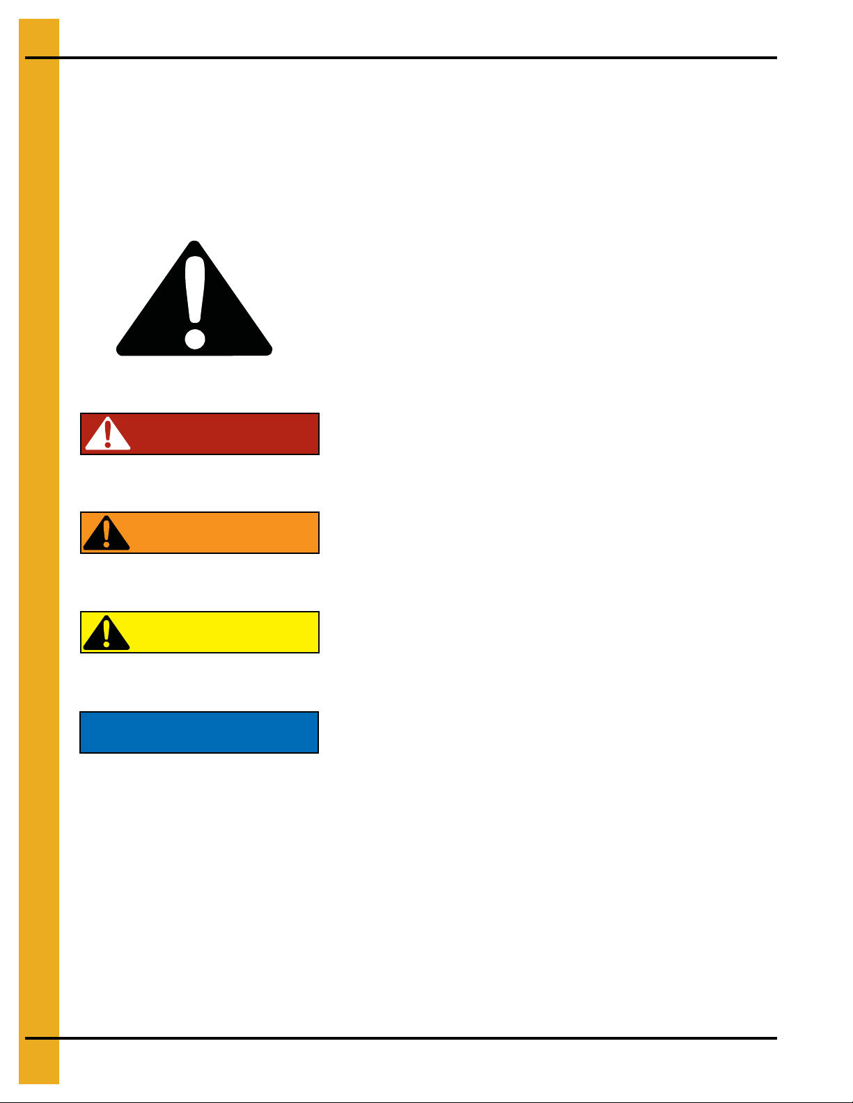
This is the safety alert symbol. It is used to alert you
to potential personal injury hazards. Obey all safety
messages that follow this symbol to avoid possible
injury or death.
WARNING indicates a hazardous situation which, if not
avoided, could result in death or serious injury.
CAUTION, used with the safety alert symbol, indicates a
hazardous situation which, if not avoided, could result in
minor or moderate injury.
NOTICE is used to address practices not related to
personal injury.
DANGER indicates a hazardous situation which, if not
avoided, will result in death or serious injury.
Safety Guidelines
This manual contains information that is important for you, the owner/operator, to know and understand.
This information relates to protecting personal safety and preventing equipment problems. It is the
responsibility of the owner/operator to inform anyone operating or working in the area of this equipment
of these safety guidelines. To help you recognize this information, we use the symbols that are defined
below. Please read the manual and pay attention to these sections. Failure to read this manual and its
safety instructions is a misuse of the equipment and may lead to serious injury or death.
DANGER
WARNING
CAUTION
NOTICE
6 PNEG-1451 Ladder, Safety Cage and Platform for Hopper Tanks
Page 7
2. Safety
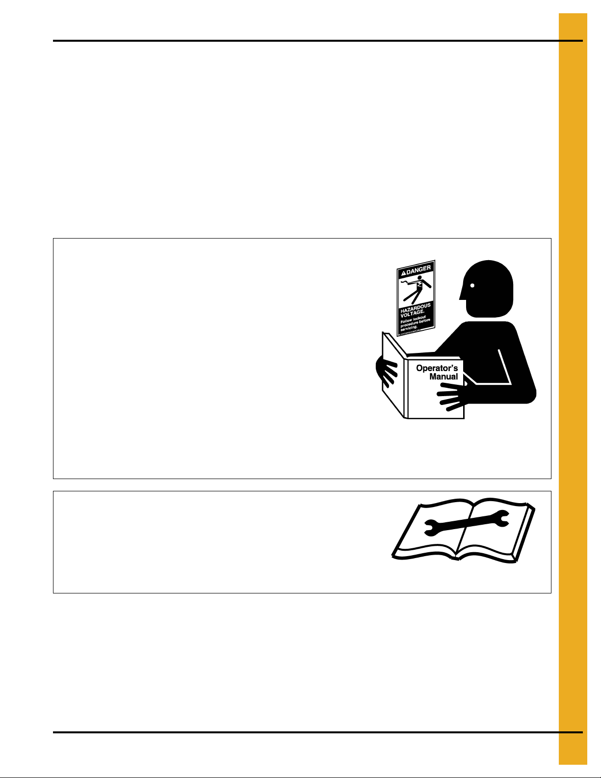
Follow Safety Instructions
Carefully read all safety messages in this manual and
safety signs on your machine. Keep signs in good
condition. Replace missing or damaged safety signs. Be
sure new equipment components and repair parts include
the current safety signs. Replacement safety signs are
available from the manufacturer.
Learn how to operate the machine and how to use controls
properly. Do not let anyone operate without instruction.
Keep your machinery in proper working condition.
Unauthorized modifications to the machine may impair
the function and/or safety and affect machine life.
If you do not understand any part of this manual or need
assistance, contact your dealer.
Read and Understand Manual
Install Equipment Properly
This equipment shall be installed in accordance with the
current installation codes and applicable regulations which
should be carefully followed in all cases. Authorities having
jurisdiction should be consulted before installations
are made.
Follow Building Codes
Safety Instructions
Our foremost concern is your safety and the safety of others associated with this equipment. We want to
keep you as a customer. This manual is to help you understand safe operating procedures and some
problems which may be encountered by the operator and other personnel.
As owner and/or operator, it is your responsibility to know what requirements, hazards and precautions
exist, and to inform all personnel associated with the equipment or in the area. Safety precautions may be
required from the personnel. Avoid any alterations to the equipment. Such alterations may produce a very
dangerous situation, where SERIOUS INJURY or DEATH may occur.
This equipment shall be installed in accordance with the current installation codes and applicable
regulations which should be carefully followed in all cases. Authorities having jurisdiction should be
consulted before installations are made.
PNEG-1451 Ladder, Safety Cage and Platform for Hopper Tanks 7
Page 8
2. Safety
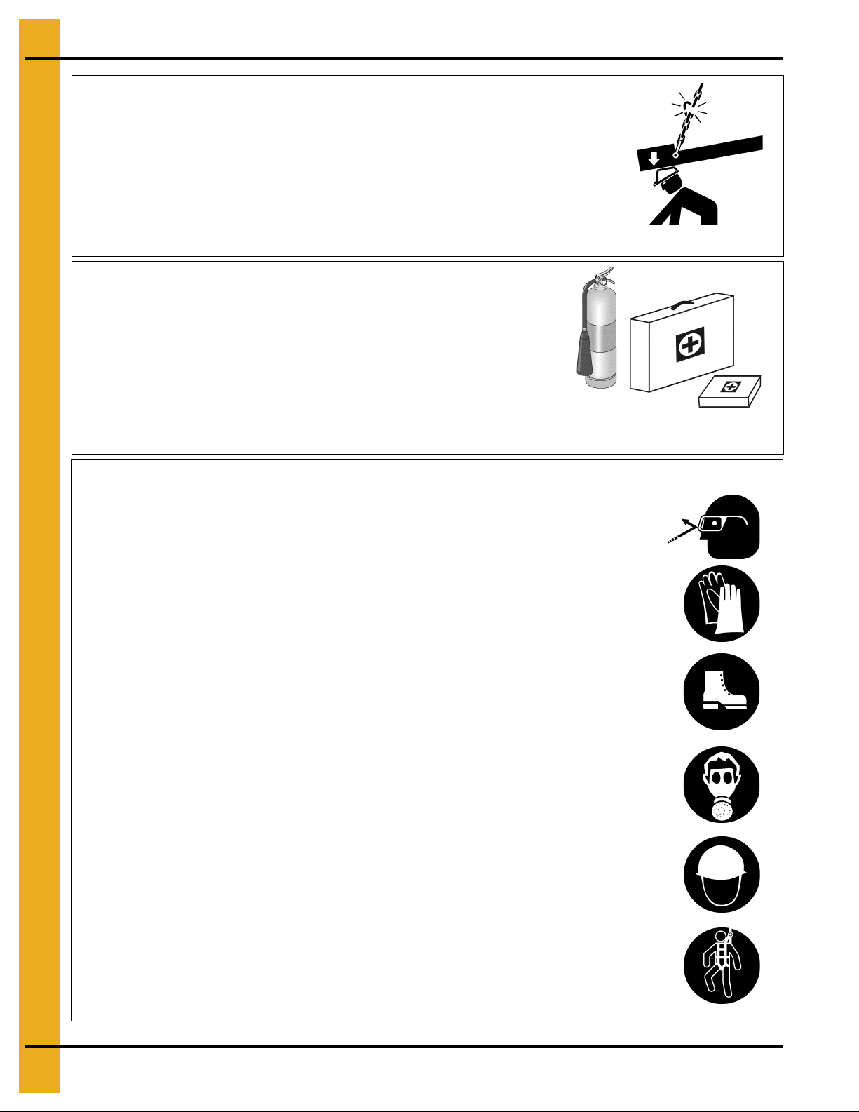
Stay Clear of Hoisted Equipment
Always use proper lifting/hoisting equipment when
assembling or disassembling equipment.
Do not walk or stand under hoisted equipment.
Always use sturdy and stable supports when needed
for installation.
Crush Hazard
Prepare for Emergencies
Be prepared if fire starts.
Keep a first aid kit and fire extinguisher handy.
Keep emergency numbers for doctors, ambulance service,
hospital and fire department near your telephone.
Keep Emergency Equipment
Quickly Accessible
Wear Protective Clothing
Wear close fitting clothing and safety equipment appropriate
to the job.
Remove all jewelry.
Long hair should be tied up and back.
Safety glasses should be worn at all times to protect eyes
from debris.
Wear gloves to protect your hands from sharp edges on
plastic or steel parts.
Wear steel toe boots to help protect your feet from falling
debris. Tuck in any loose or dangling shoe strings.
A respirator may be needed to prevent breathing potentially
toxic fumes and dust.
Wear hard hat to help protect your head.
Wear appropriate fall protection equipment when working at
elevations greater than six feet (6').
Eye Protection
Gloves
Steel Toe Boots
Respirator
Hard Hat
Fall Protection
8 PNEG-1451 Ladder, Safety Cage and Platform for Hopper Tanks
Page 9
3. Safety Decals
The manufacturer does not warrant any roof damage caused by excess ive v acuum or internal
pressure from fans or other air moving systems. Adequate ventilation and/or “makeup air”
devices should be provided for all powered air handling systems. The manufacturer does not
recommend the use of downward flow systems (suction). Severe roof damage can result from
any blockage of air passages. Running fans durin g high humidity/cold weather conditions can
cause air exhaust or intake ports to freeze.
Roof Damage Warning and Disclaimer
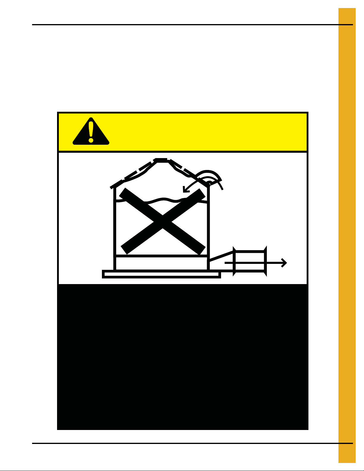
CAUTION!
Excessive vacuum (or pressure) may
damage roof. Use positive aeration
system. Make sure all roof vents are
open and unobstructed. Start roof
fans when supply fans are started.
Do not operate when conditions exist
that may cause roof vent icing.
DC-969
PNEG-1451 Ladder, Safety Cage and Platform for Hopper Tanks 9
Page 10
3. Safety Decals
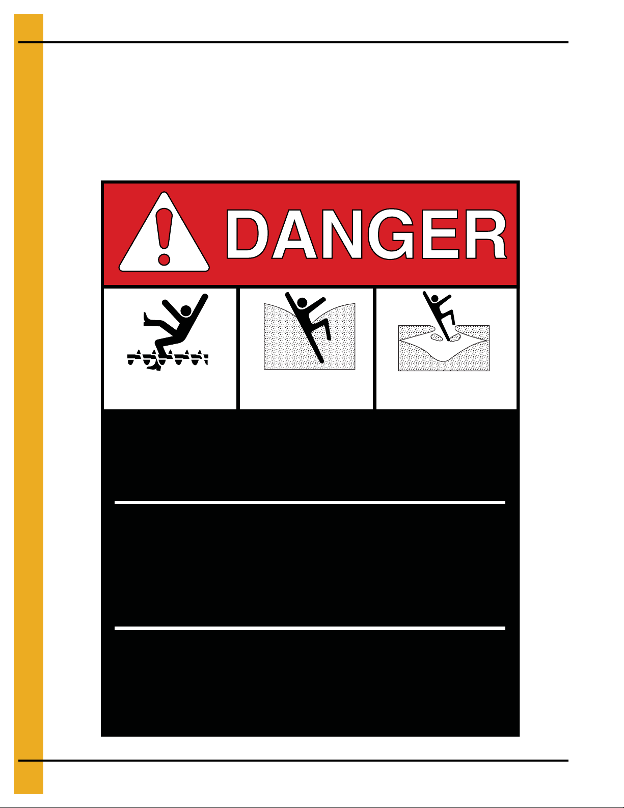
Rotating flighting will
kill or dismember.
Flowing material will
trap and suffocate.
Crusted material will
collapse and suffocate.
Keep clear of all augers.
DO NOT ENTER this bin!
Failure to heed these
warnings will result in
serious injury or death.
If you must enter the bin:
1. Shut off and lock out all power.
2. Use a safety harness and safety line.
3. Station another person outside the bin.
4. Avoid the center of the bin.
5. Wear proper breathing equipment or respirator.
DC-GBC-1A
ATTENTION: The decal shown below should be present on the outside of t he door cover of the 2 ring on
the 24" porthole door cover, and on the roof manway cover. If a decal has been damaged or is missing in
any of these locations, contact the manufacturer for a free replacement decal.
GSI Decals
1004 E. Illinois St.
Assumption, IL. 62510
Phone: 1-217-226-4421
10 PNEG-1451 Ladder, Safety Cage and Platform for Hopper Tanks
Page 11
3. Safety Decals
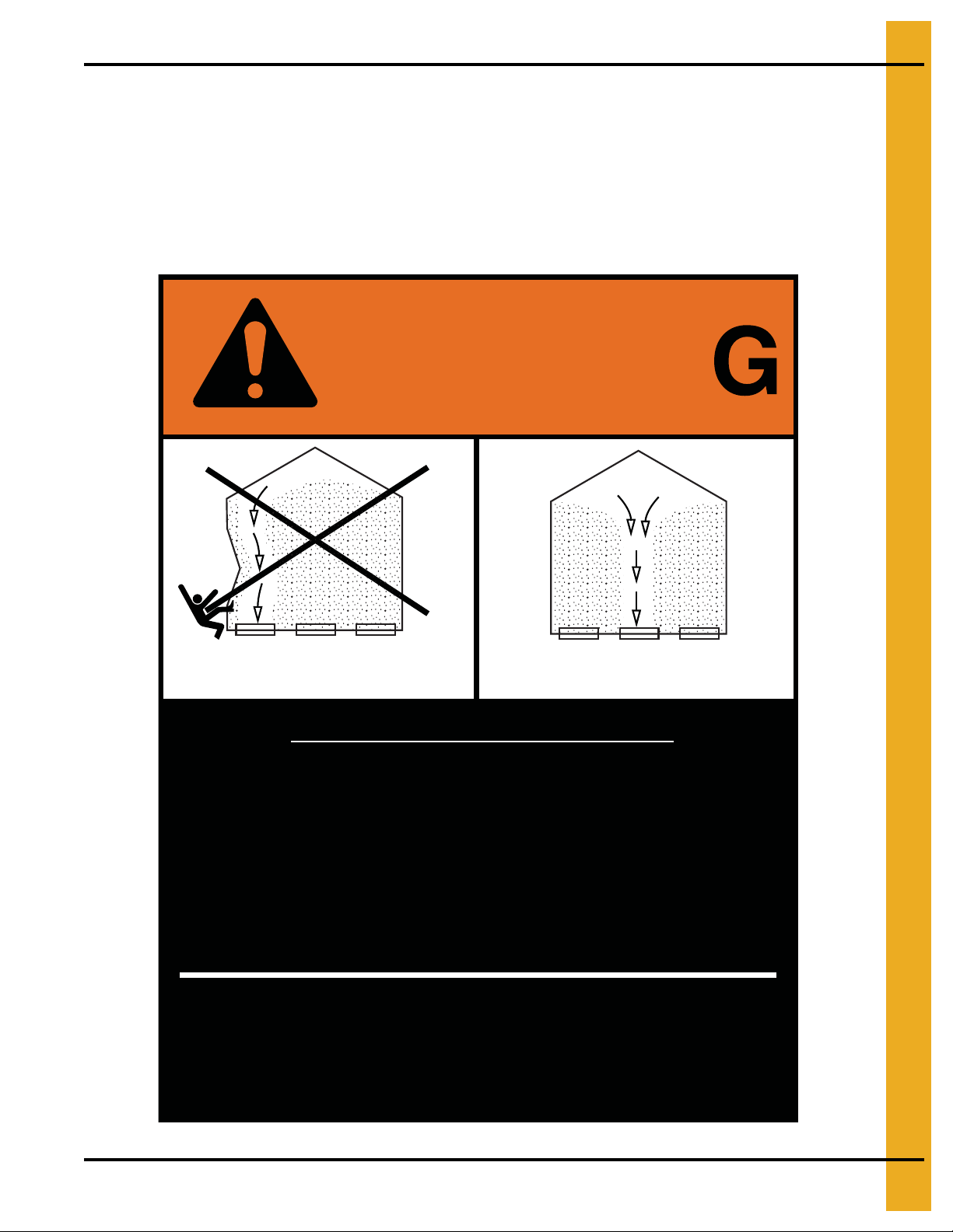
Failure to heed these warnings
could result in serious injury, death,
structural damage or collapse of tank.
1. Use CENTER FLOOR OUTLET ONLY until NO grain
remains above this outlet.
2. Side floor outlets to be used ONLY when above
condition is satisfied.
3. Lock all side floor outlets to avoid accidental
premature use.
4. See manufacturers instructions for proper use of
factory supplied sidedraw (wall) discharge systems.
UNLOADING INSTRUCTIONS:
DC-GBC-2A
WARNIN
DON’T
DO
ATTENTION: The decal shown below should be present on the outside of the door cover of the 2 ring on
the 24" porthole door cover, and on the roof manway cover. If a decal has been damaged or is missing in
any of these locations, contact the manufacturer for a free replacement decal.
GSI Decals
1004 E. Illinois St.
Assumption, IL. 62510
Phone: 1-217-226-4421
PNEG-1451 Ladder, Safety Cage and Platform for Hopper Tanks 11
Page 12
4. General Detail Information
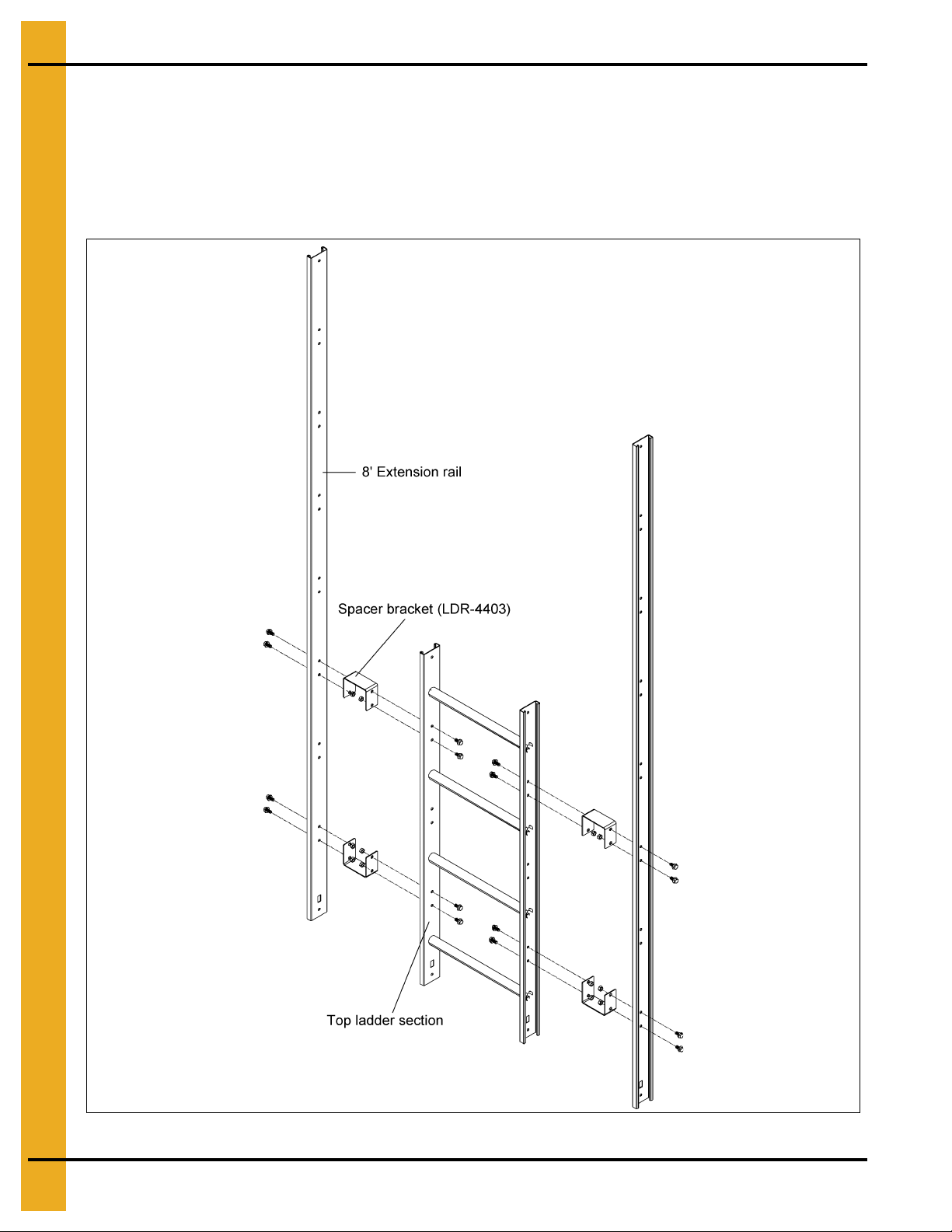
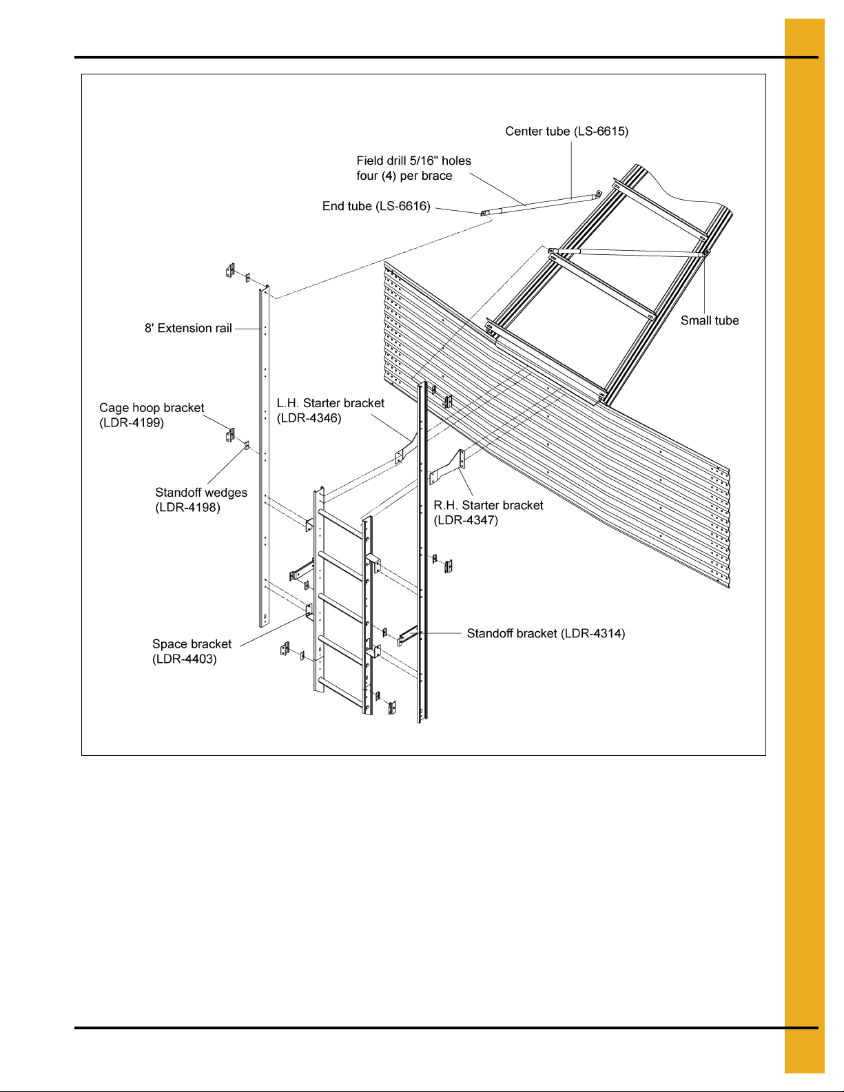
Extension Rail Installation
All ladder systems that include a safety cage must also include ladder extension rails attached to the top
four foot (4') ladder section. Start by bolting the spacer brackets through the top and bottom set of holes
in the top ladder section. Then, attach the extension rails to the spacer brackets as shown in Figure 4A.
When installed correctly, the bottom of the extension rail should be flush with the bottom of the top ladder
section. Use 5/16" x 3/4" bin bolts for all connections.
Figure 4A Ladder Extension
12 PNEG-1451 Ladder, Safety Cage and Platform for Hopper Tanks
Page 13
4. General Detail Information
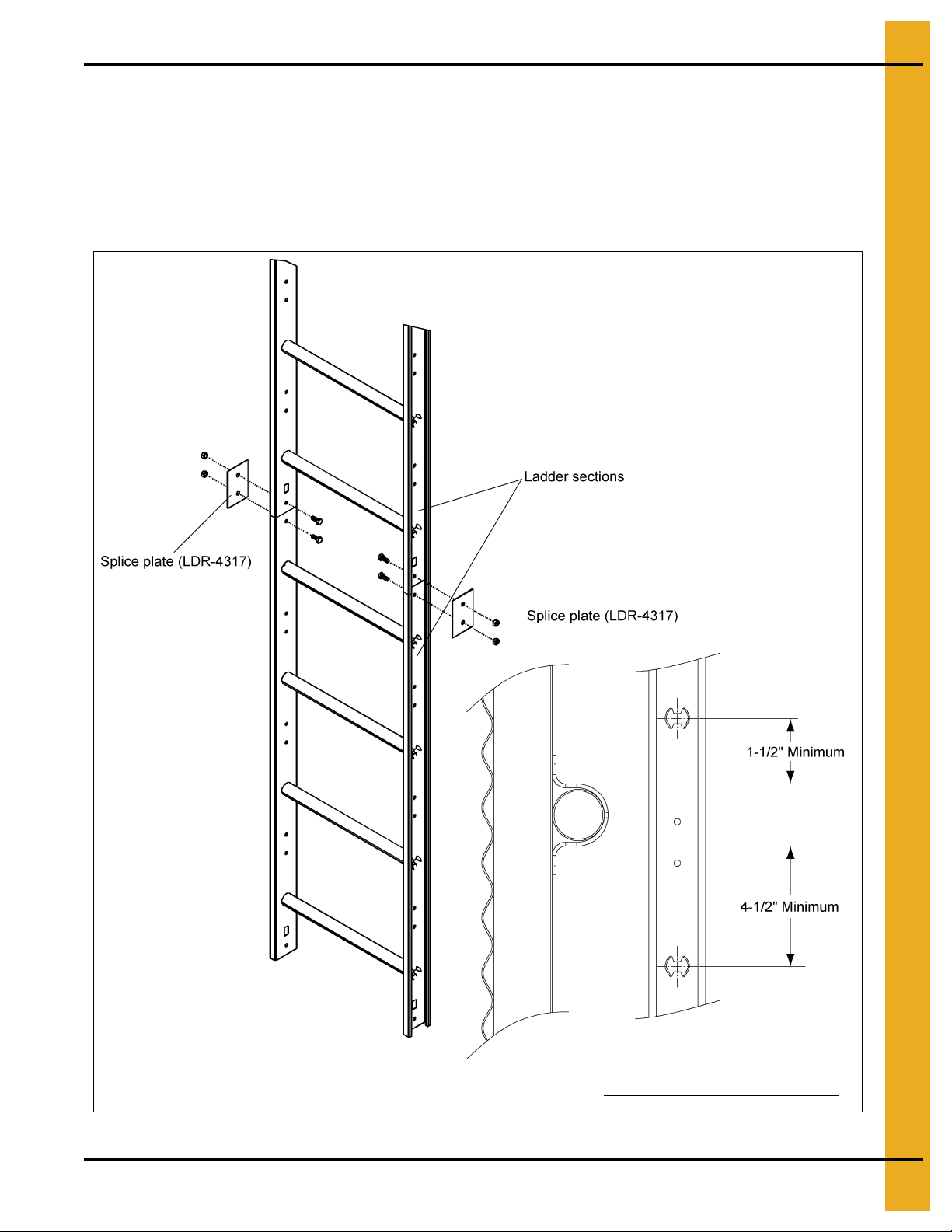
Wind rings must be installed in relation to the ladder rungs as
shown here, to insure compliance with O.S.H.A. regulations.
Ladder Section Assembly
Two (2) splice plates (LDR-4317) are required to attach each ladder section. The head of the bolt
should be to the inside of the ladder with the splice plate on the outside as shown in Figure 4B.
Use 5/16" x 3/4" bolts for all connections.
NOTE: With most installations, the last ladder section installed to reach the ground, the base or the
intermediate platform should be cut to fit.
PNEG-1451 Ladder, Safety Cage and Platform for Hopper Tanks 13
Figure 4B
Page 14
4. General Detail Information
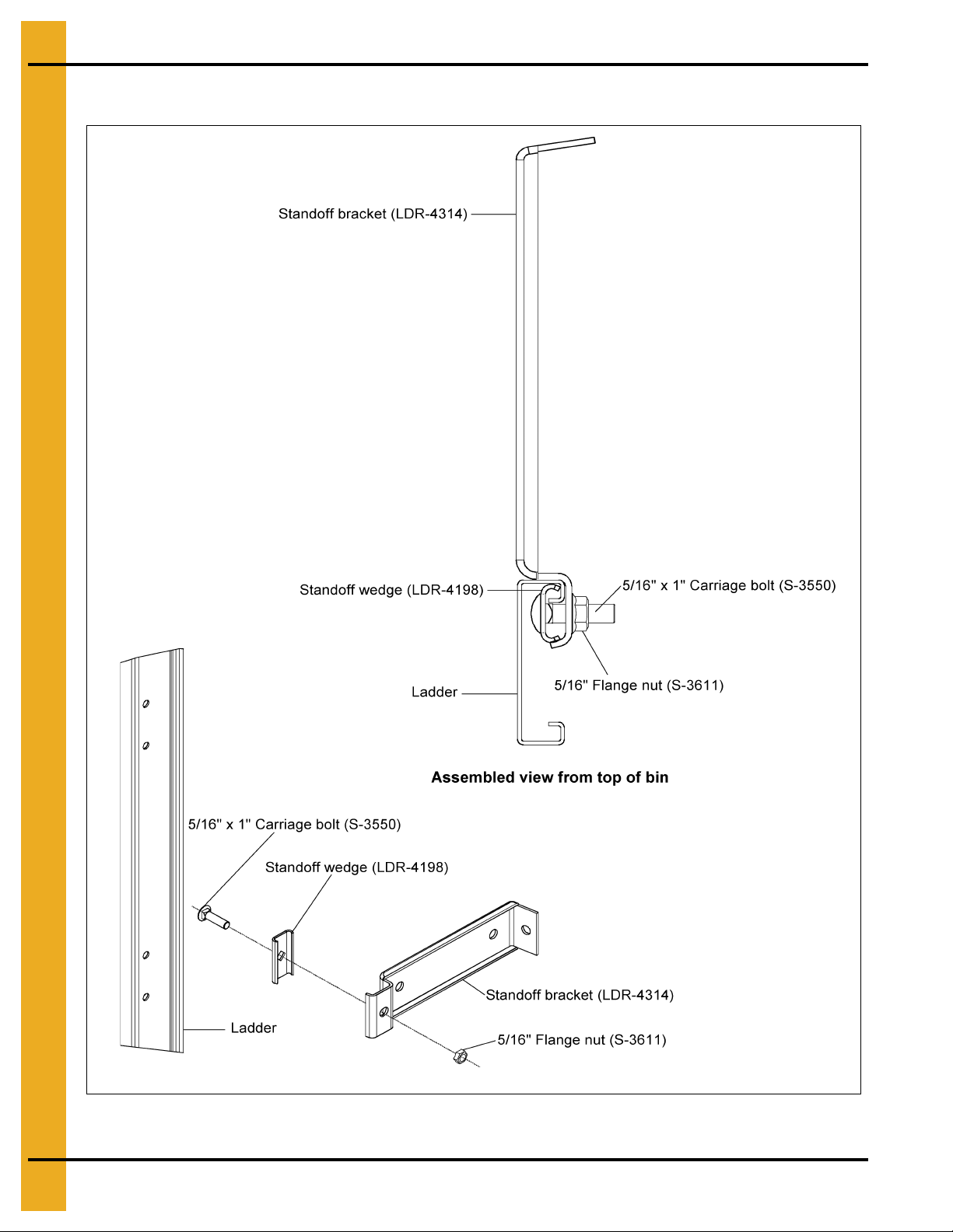
Ladder Standoff Detail
Figure 4C
14 PNEG-1451 Ladder, Safety Cage and Platform for Hopper Tanks
Page 15
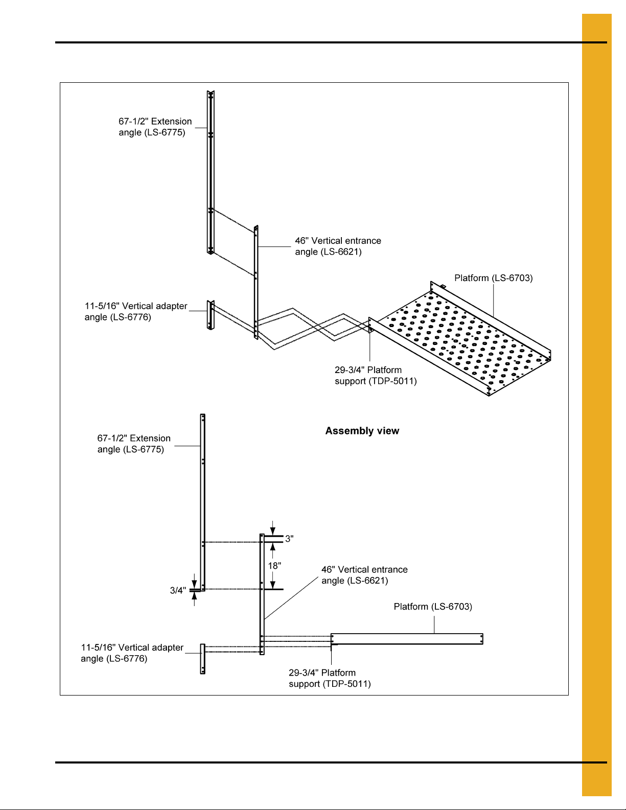
Extension Angle Hole Detail
4. General Detail Information
Figure 4D
NOTE: Platform and platform support shown for reference only. See platform assembly detail on Pa ge 47
for complete installation instructions for these parts.
PNEG-1451 Ladder, Safety Cage and Platform for Hopper Tanks 15
Page 16
4. General Detail Information
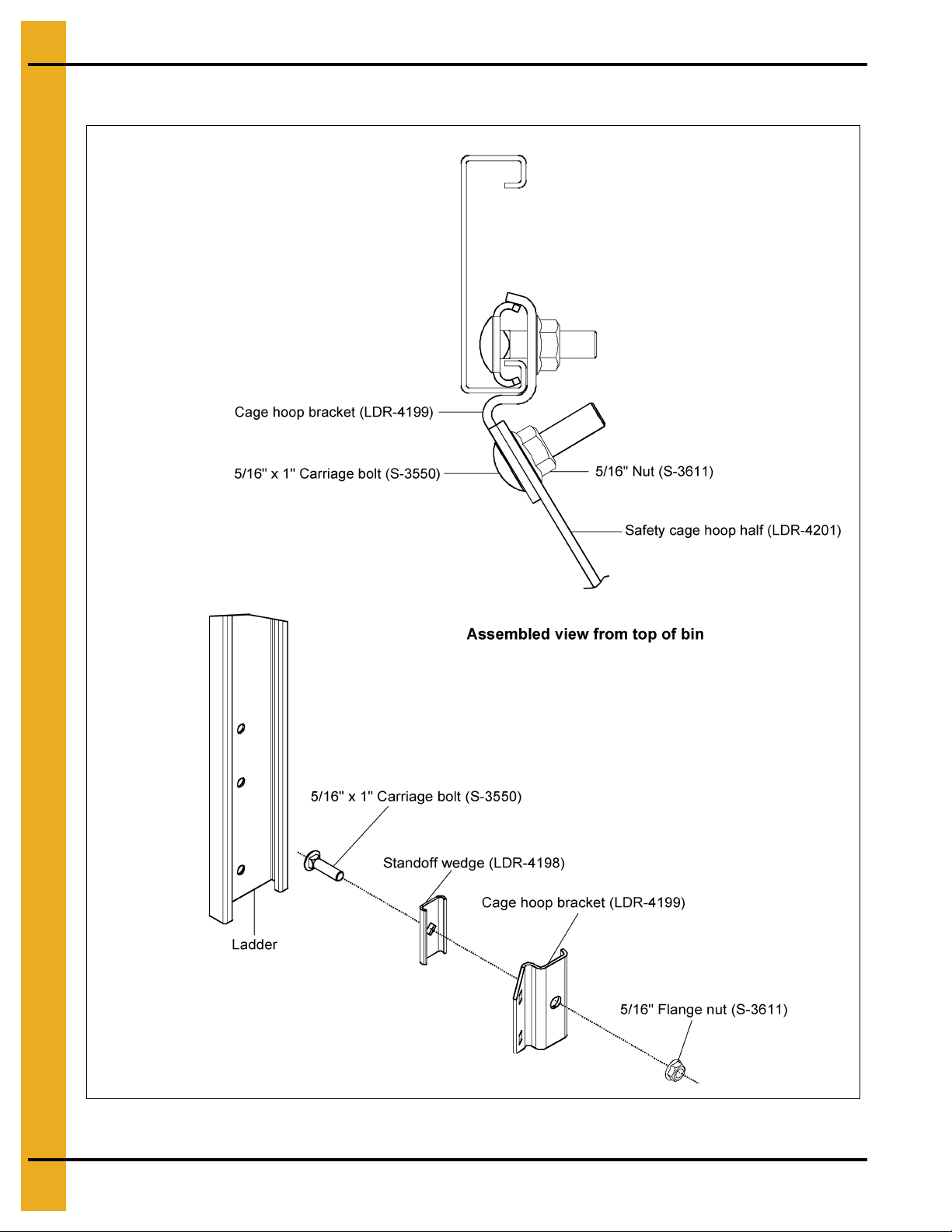
NOTE: Leave bolt loose until cage
hoop half has been attached.
Cage Hoop Bracket Assembly
Figure 4E
16 PNEG-1451 Ladder, Safety Cage and Platform for Hopper Tanks
Page 17
4. General Detail Information
Figure 4F
PNEG-1451 Ladder, Safety Cage and Platform for Hopper Tanks 17
Page 18

NOTES
18 PNEG-1451 Ladder, Safety Cage and Platform for Hopper Tanks
Page 19

PNEG-1451 Ladder, Safety Cage and Platform for Hopper Tanks 19
2.66" Corrugated
Commercial Hopper
Tank 4-9 Rings
®
Page 20
5. 2.66" Corrugated Commercial Hopper Tank 4-9 Rings
32" Safety cage
sections (See note
on page 21.)
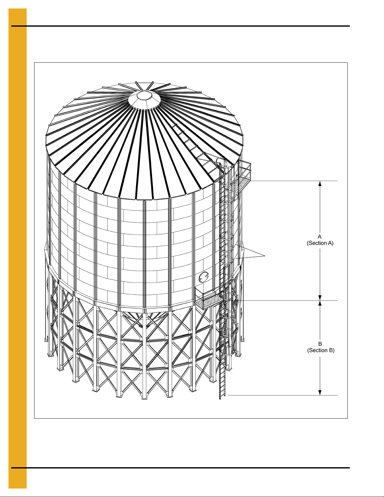
2.66" Commercial Hopper Tank (NCHT) Ladder and Platform
Layout 4-9 Rings
Figure 5A 9 Rings
See Page 21 for platform locations and section listings.
20 PNEG-1451 Ladder, Safety Cage and Platform for Hopper Tanks
Page 21
5. 2.66" Corrugated Commercial Hopper Tank 4-9 Rings
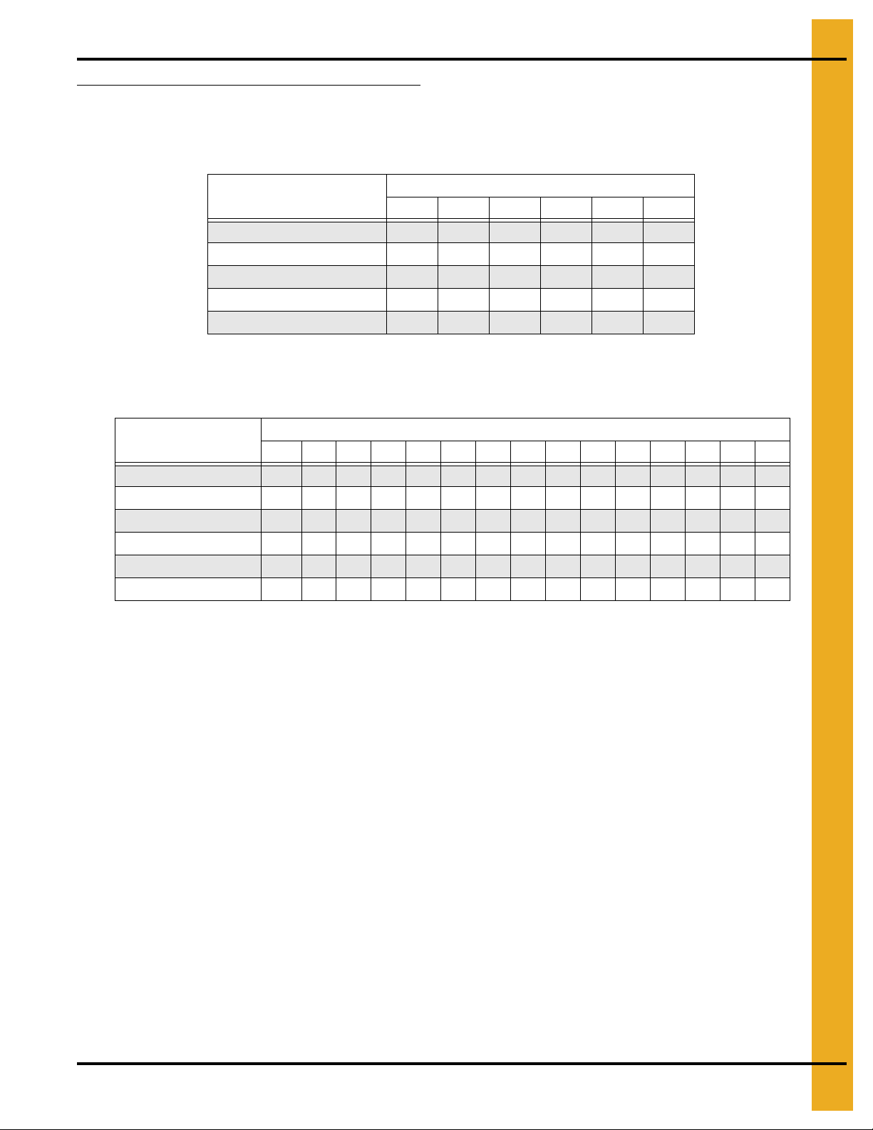
Ladder, Safety Cage and Platform Location Chart
For Section A, find the proper ring grain bin and use the number of ladders and safety cages indicated.
See Chart below (Section A). For Section B, find the proper diameter grain bin and hopper slope, then use
the number of ladders and safety cages indicated. See Chart below (Section B).
Rings
456789
Platform Located in Ring: 2 2 2 2 2 2
4' Ladder Section 3 4 4 5 6 6
Safety Cage 32" Section 0 1 2 0 1 2
Safety Cage 48" Section 000222
Section A
Dimension A 96" 128" 160" 192" 224" 256"
NOTE: The 32" safety cage section must be installed in Section A of the ladder system. DO NOT install
the 32" verticals in the eave or access door safety cage hoop assembly. The eave and access door
safety cage hoop assembly use the 48" verticals.
Diameter
12' 12' 15' 15' 18' 18' 21' 21' 24' 27' 27' 30' 30' 36' 36'
Hopper Slope: 45 60 45 60 45 60 45 60 45 40 45 40 45 40 45
4' Ladder Section 4 55657576566767
Bell Safety Cage 0 1 0 1 1 1 1 1 1 1 1 1 1 1 1
Safety Cage 48" Section0 00101020010112
Section B
Bell Safety Cage Size N/A 24" N/A 24" 24" 48" 48" 24" 48" 48" 24" 48" 48" 48" 48"
Dimension B 91" 128" 108" 167" 128" 198" 144" 229" 162" 142" 179" 156" 195" 187" 236"
PNEG-1451 Ladder, Safety Cage and Platform for Hopper Tanks 21
Page 22

5. 2.66" Corrugated Commercial Hopper Tank 4-9 Rings
NCHT Ladder, Safety Cage and Platform Instructions 4-9 Rings
All grain bin packages, from 4 ring to 9 ring and 12' to 35' diameter, contain the correct components for
assembly. Read and follow the complete instructions for correct placement of parts. Be sure and use the
charts to determine the appropriate number and size parts to be used based upon the number of rings in
the bin. Failure to do so may result in an improper fit or shortage of parts. Pay particular attention to the
location of ladders and platforms as they relate to the other equipment and structures in the area.
Eave Starter Bracket Installation
Correct placement of the eave ladder starter bracket is critical to assure proper fit of all ladder co mponents
and to assure the correlation is correct between the platforms for proper installation of the access door
platform. If the eave starter brackets are mislocated, standard installation of the access door platform will
not be possible.
22 PNEG-1451 Ladder, Safety Cage and Platform for Hopper Tanks
Page 23
5. 2.66" Corrugated Commercial Hopper Tank 4-9 Rings
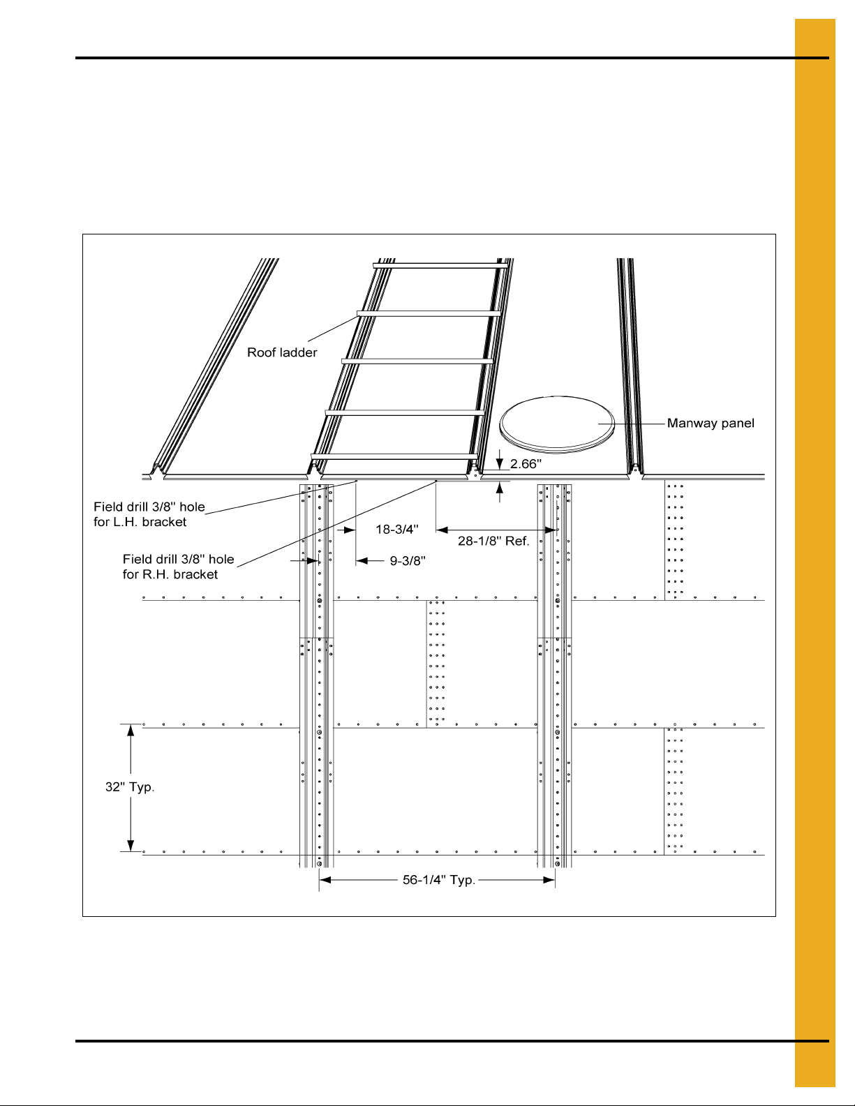
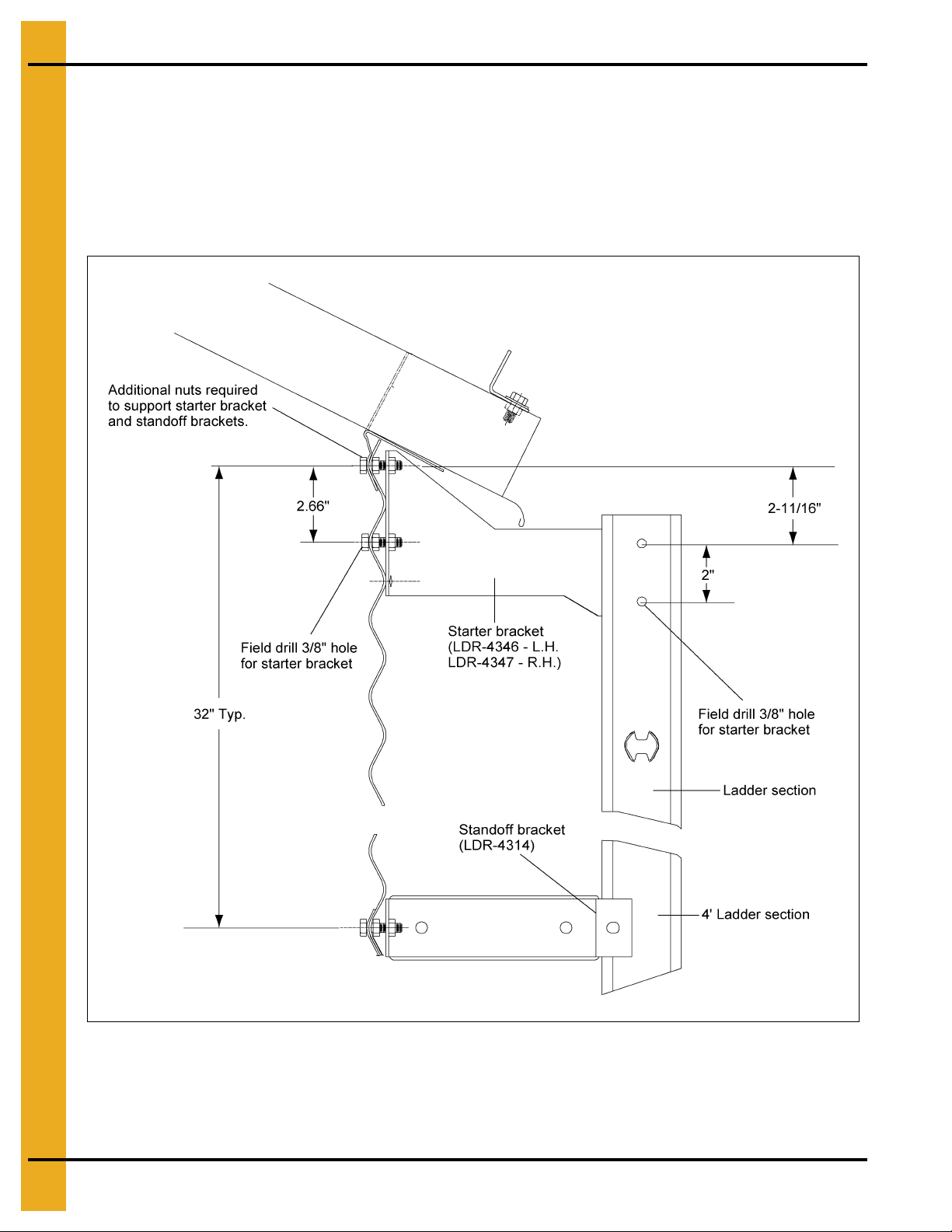
Location of Field Drilled Holes for Eave Ladder Starter Brackets
The starter brackets must be located directly below the roof ladder. Before the starter brackets can be
installed, two (2) 3/8" holes must be field drilled 2.66" below and directly in line with the top row of
pre-punched horizontal holes. The first hole, required for the left hand starter bracket, must be located
9-3/8" from the center of the stiffener to the center of the hole as shown in Figure 5B. The second
hole, required for the right hand bracket, must be located 18-3/4" from the center of the first hole. Refer to
Figure 5B for the proper location of the two (2) 3/8" field drilled holes required to install the starter brackets.
Figure 5B
PNEG-1451 Ladder, Safety Cage and Platform for Hopper Tanks 23
Page 24
5. 2.66" Corrugated Commercial Hopper Tank 4-9 Rings
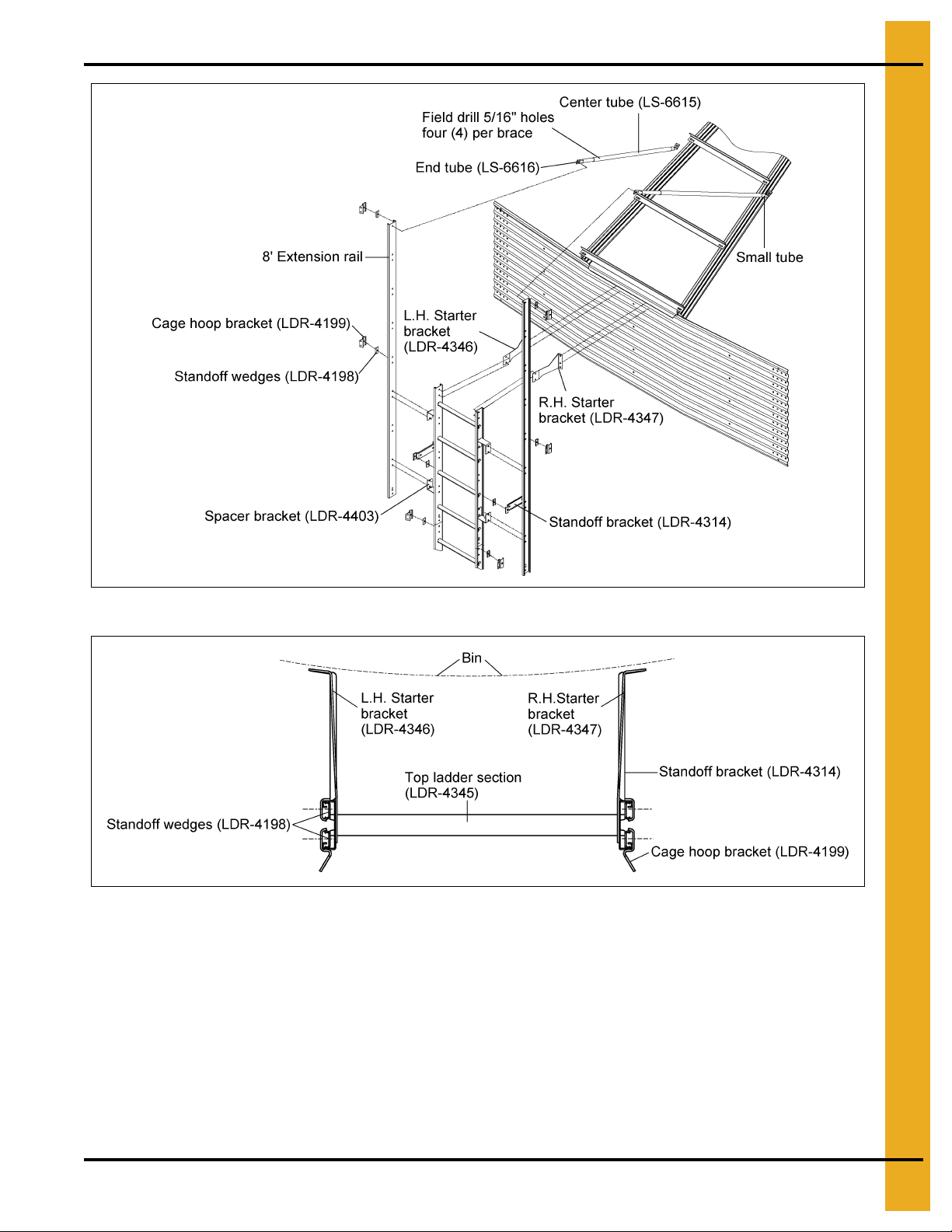
Eave Starter Bracket and Ladder Assembly with Safety Cage
Once the two (2) 3/8" holes have been field drilled, attach the starter brackets to the sidewall as shown in
Figure 5C. Check the top ladder section to make sure the ladder rung dimples are to the top. Attach starter
brackets to the top of the ladder. See Figure 4B on Page 13 for the pro per installation of addit ional ladder
sections required. Standoff brackets must be installed on the ladder sections an d attached to the sidewall
at each horizontal seam and repeated every 32". Use 5/16" x 3/4" bin bolts for all connections. It is also
necessary to field drill a 3/8" hole on the ladder section for each starter bracket (L.H. and R.H.).
Figure 5C
NOTE: Refer to general detail information on Page 12 for additional d etails for sta ndoff bracket to ladde r
assembly and also, 8' extension rail installation (omitted in detailed figure above for clarity).
24 PNEG-1451 Ladder, Safety Cage and Platform for Hopper Tanks
Page 25
5. 2.66" Corrugated Commercial Hopper Tank 4-9 Rings
Figure 5D
Figure 5E Ladder and Bracket as Viewed from Top of Bin
PNEG-1451 Ladder, Safety Cage and Platform for Hopper Tanks 25
Page 26
5. 2.66" Corrugated Commercial Hopper Tank 4-9 Rings
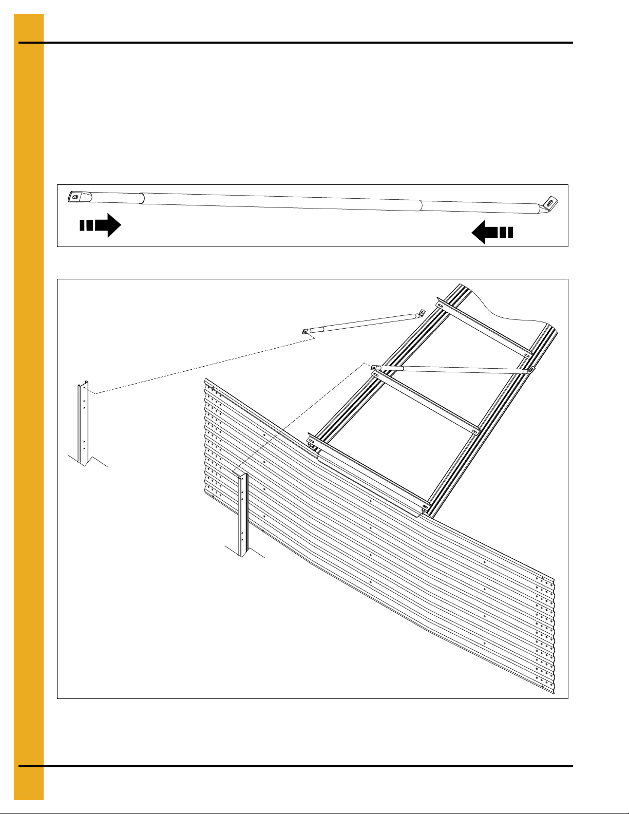
Eave Adjustable Braces
The eave adjustable braces must be attached at this time. An eave adjustable brace is comprised of
one large diameter tube and two (2) smaller diameter tubes. (See Figure 5F.) Slide the smaller tubes
inside the larger tubes and attach one smaller tube to the top of the ladder extension rail. Adjust the other
smaller tube so the bottom of the flattened tube reaches the roof panel. Field drill four (4) 5/16" holes
through both large and small tubes and bolt together using 1/4" x 1-1/2" bolts and nuts. This will prevent
the adjustable braces from slipping. (See Figure 5G.)
NOTE: Refer to Page 24 for proper location of ladder starter brackets.
Figure 5F
Figure 5G
NOTE: Refer to Figure 4A on Page 12 for additional details for standoff bracket to ladder assembly and
cage hoop bracket to ladder.
26 PNEG-1451 Ladder, Safety Cage and Platform for Hopper Tanks
Page 27
5. 2.66" Corrugated Commercial Hopper Tank 4-9 Rings
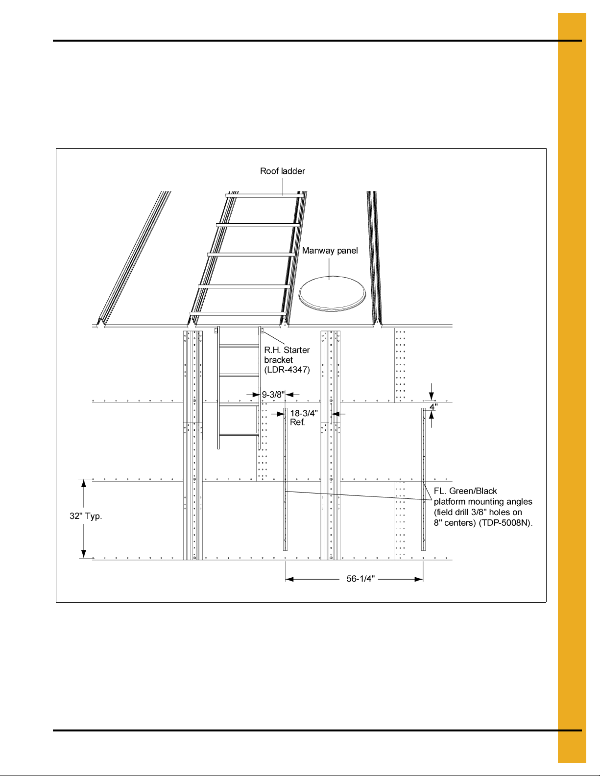
Eave Platform Mounting Angle Installation
Figure 5H shows the location of the platform mounting angles. Each angle must be mounted starting
4" below the top horizontal seam of the second ring with the first mounting angle offset 9-3/8" from the
right hand starter bracket. The second mounting angle must be located 56-1/4" from the first mounting
angle. The dimensions and locations of these angles are critical for proper fit of all parts. Using the platform
mounting angels as guides, field drill 3/8" holes in the sidewall every 8". (See Figure 5H.)
Figure 5H
PNEG-1451 Ladder, Safety Cage and Platform for Hopper Tanks 27
Page 28
5. 2.66" Corrugated Commercial Hopper Tank 4-9 Rings
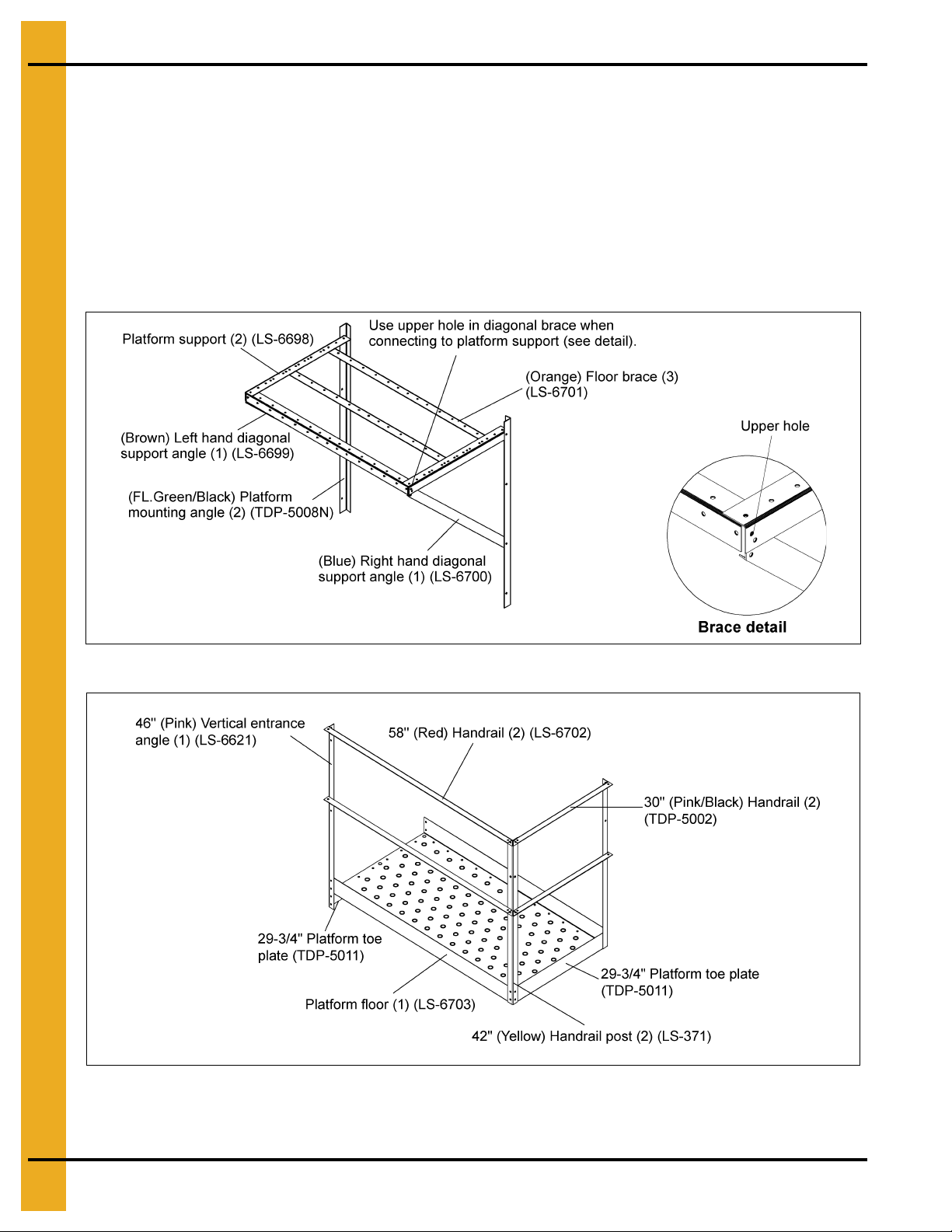
Right Hand Platform and Platform Support Assembly
NOTE:
Assemble the platform support frame using 5/16" x 3/4" truss head bolts and nuts. (See Figure 5I.) Wh en
attaching the platform mounting angles to the sidewall, locate the mounting angles according to the
instructions on previous pages. Align holes on the platform floor with the holes on the platform supports
and bolt together using 5/16" x 3/4" truss head bolts and nuts. Attach platform toe plates at the same time
as attaching the platform floor. The vertical entrance angle bolts to the platform floor, toe plate and
platform support. The handrail post bolts to the platform floor and toe plate as shown in Figure 5J.
Mount the platform supports on the bin first. Next, assemble the platform floor onto the support
frame. Do not tighten platform support to floor brace bolts until the floor and toe plates are secure.
Figure 5I Right Hand Platform Support Assembly
Figure 5J Right hand platform
28 PNEG-1451 Ladder, Safety Cage and Platform for Hopper Tanks
Page 29
5. 2.66" Corrugated Commercial Hopper Tank 4-9 Rings
67-1/2" Extension angles (LS-6775)
(See extension angle hole detail
on Page 15 for proper installation.)
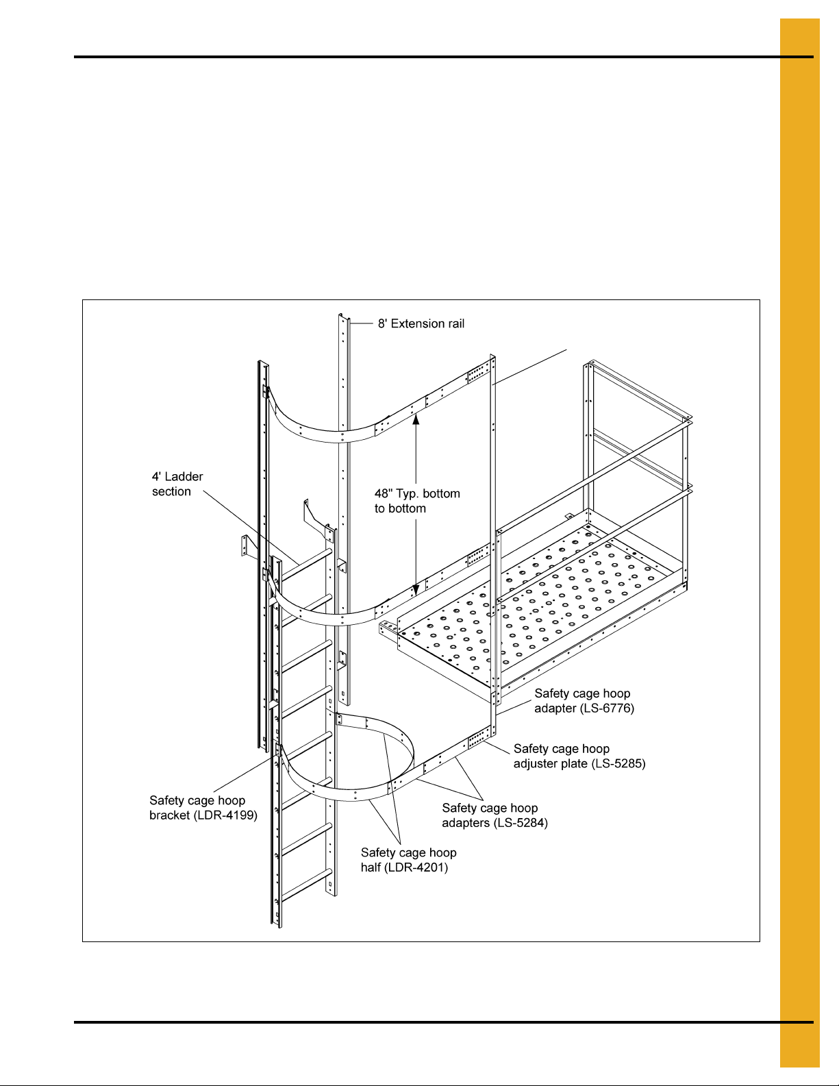
Eave Safety Cage Hoop Assembly
Before attaching any pieces to the ladders or platform, some pre-assembly is required. Attach two (2)
safety cage brackets to the 8' extension rail and one safety cage bracket to the second 4' ladder section
as shown in Figure 5K. Bolt the safety cage hoop adjuster plates onto the extension angle as shown in
Figure 5K. Using the proper configuration depending on the bin diameter (see adapter assembly detail
on Page 30), bolt the safety cage hoop adapters together and attach to the safety cage hoop halves.
Be sure to use the 5/16" x 3/4" bolt with the head of the bolt to the inside of the safety cage. Bolt these
assemblies to the safety cage brackets and hoop adjuster plates (See connection detail on Page 30 for
proper hole location). Tighten bolts as you go. The bottom asse mbly requires two (2) hoop halves and will
be positioned just below the platform as shown in Figure 5K. Use the safety cage hoop adjuster angle to
secure the two (2) hoop half assemblies to the vertical entrance angle on the platform assembly.
NOTE: 48" Vertical supports removed in Figure 5K for clarity.
PNEG-1451 Ladder, Safety Cage and Platform for Hopper Tanks 29
Figure 5K
Page 30
5. 2.66" Corrugated Commercial Hopper Tank 4-9 Rings
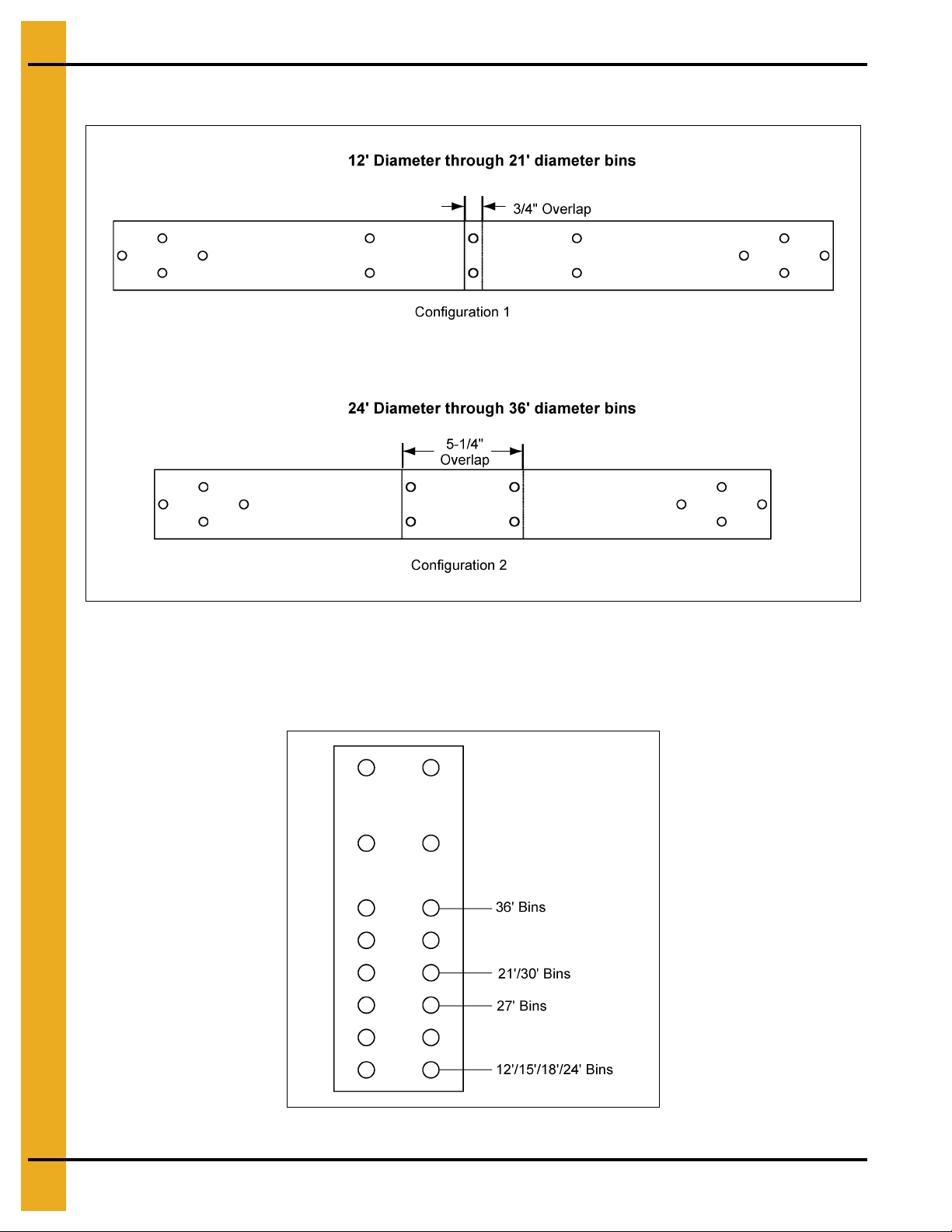
Adapter Assembly Detail
Connection Detail
Use
Figure 5M
to determine the proper holes to use when attaching the hoop adapter to the adjuster plate.
Figure 5L
Figure 5M
30 PNEG-1451 Ladder, Safety Cage and Platform for Hopper Tanks
Page 31

5. 2.66" Corrugated Commercial Hopper Tank 4-9 Rings
Vertical Supports
After all three (3) hoop assemblies
are in place, attach the 48" vertical
supports from hoop assembly to hoop
assembly, as shown in Figure 5N.
This requires ten (10) supports, five (5)
between each set of hoops. The second
set of vertical supports must be bent at
the flat area to allow for the tapering
of the bottom hoop assembly. Use
5/16" x 3/4" bolts (unless otherwise
noted) with the head of the bolt to the
inside of the safety cage.
Figure 5N Vertical Supports
32" and 48" Safety Cage
Attach the vertical support pieces to the existing hoop halves using the 5/16" x 3/4" bolts and nuts (with
the heads on the inside of the cage). Fasten two (2) hoop halves together and bolt to other end of vertical
supports. Attach cage hoop brackets to ladder, Refer to Figure 5K on Page 29 for proper attachment.
Once cage hoop brackets have been installed, attach cage hoop halves and tighten bolts. Repeat
installation for each safety cage required.
Figure 5O 32" Safety Cage
PNEG-1451 Ladder, Safety Cage and Platform for Hopper Tanks 31
Figure 5P 48" Safety Cage
Page 32

5. 2.66" Corrugated Commercial Hopper Tank 4-9 Rings
Access Door Platform Mounting Angle Installation
Figure 5Q
32 PNEG-1451 Ladder, Safety Cage and Platform for Hopper Tanks
Page 33

5. 2.66" Corrugated Commercial Hopper Tank 4-9 Rings
Left Hand Platform and Platform Support Assembly
NOTE: Mount the platform mounting angles on the columns first. Next, assemble the platform floor onto
the support frame. Do not tighten platform support to floor brace bo lts until the floor and toe plates
are secure.
Assemble the platform support frame using 5/16" x 3/4" truss head bolts and nuts. Align holes on the
platform floor with the holes on platform supports and bolt together using 5/16" x 3/4" truss head bolts and
nuts. Attach platform toe plates at the same time as attaching the platform floor. Vertical entrance angle
bolts to the platform floor, toe plate and platform support. Handrail post b olts to the pla tform floor and toe
plate as shown in Figure 5S.
Figure 5R Left Hand Platform Support Assembly
Figure 5S Left Hand Platform
PNEG-1451 Ladder, Safety Cage and Platform for Hopper Tanks 33
Page 34

5. 2.66" Corrugated Commercial Hopper Tank 4-9 Rings
Left hand platform
assembly (See Page 32
for assembly details.)
Extension angle (LS-6775) (See general detail
information on Page 12 for proper installation.)
32" Safety cage assemblies shown
for reference only. See Page 32 for
installation details.
Access Door Safety Cage Hoop Assembly
Before attaching any pieces to the ladder or platform, some pre-assembly is required. Attach the safety
cage brackets to the ladder section.
onto the extension angle as shown in
adapters and safety cage hoop half together using the proper holes, based upon the bin diameter.
(See Page 30.)
Be sure to use the 5/16" x 3/4" bolt with the head of the bolt to the inside of the safety
cage. Bolt this assembly to the safety cage bracket and hoop adjuster plate, tighten as you go. The bottom
assembly requires two (2) hoop halves and will be positioned just below the platform as shown in
Use the safety cage hoop adjuster angle to secure the two (2) hoop half assemblies to the vertical entrance
angle on the platform assembly. To finish the installation, secure the access door platform assembly to the
existing safety cage assembly using the safety cage hoop adapters as shown in
NOTE: See Pages 31 and 35 for vertical supports, safety cage installation an d bell safety cage installation
details to complete the ladder assembly.
(See Figure 5K on Page 29.)
Figure 5T
. For the middle hoop assembly, bolt the safety cage hoop
Bolt the safety cage hoop adjuster plates
Figure 5T
Figure 5T
.
.
Figure 5T
34 PNEG-1451 Ladder, Safety Cage and Platform for Hopper Tanks
Page 35

5. 2.66" Corrugated Commercial Hopper Tank 4-9 Rings
24"-48" Safety Cage Bell Sections
Attach the vertical supports to the hoop half assembly from the final safety cage installation using
5/16" x 3/4" bolts and nuts (with the heads on the inside of the cage). Assemble the special bell safety
cage hoop halves and attach to other end of vertical supports. The vertical support must be bent at the flat
area to allow for the angle of the bell section. Attach the safety cage brackets to the ladder as shown in
the Figure 5K on Page 29. Once the safety cage brackets are installed, attach the bell safety cage hoop
half assembly to the safety cage brackets and tighten bolts.
NOTE: The safety cage bell section is to be used at the poi nt of termination of the safety cage an d should
be just above the concrete (generally 7' to 8').
Figure 5U 24" Bell
Figure 5V 48" Bell
PNEG-1451 Ladder, Safety Cage and Platform for Hopper Tanks 35
Page 36

5. 2.66" Corrugated Commercial Hopper Tank 4-9 Rings
Ladder Support Detail
The ladder must be secured to the hopper support columns with ladder standoff brackets using support
channels and ladder brackets as shown in Figure 5W.
Figure 5W
Tank Diameter Hopper Slope No. of Support Channels Hopper Ladder Brackets
12' 45 3 6
12' 60 4 8
15' 45 3 6
15' 60 5 10
18' 45 4 8
18' 60 6 12
21' 45 4 8
21' 60 7 14
24' 45 5 10
27' 40 4 8
30' 40 4 8
36' 40 5 10
36' 45 7 14
36 PNEG-1451 Ladder, Safety Cage and Platform for Hopper Tanks
Page 37

PNEG-1451 Ladder, Safety Cage and Platform for Hopper Tanks 37
2.66" Corrugated
Commercial Hopper
Tank 10-22 Rings
®
Page 38

6. 2.66" Corrugated Commercial Hopper Tank 10-22 Rings
2.66" Commercial Hopper Tank (NCHT) Ladder and Platform
Layout 10-22 Rings
Figure 6A 17 Rings
38 PNEG-1451 Ladder, Safety Cage and Platform for Hopper Tanks
Page 39

6. 2.66" Corrugated Commercial Hopper Tank 10-22 Rings
Ladder, Safety Cage and Platform Location Chart
For Section A through C, find the proper ring grain bin and use the number of ladders and safety cages
as shown in the Chart below. For Section D, find the proper diameter grain bin and hopper slope and use
the number of ladders and safety cages as shown in the Chart on Page 41.
Rings
10 11 12 13 14 15 16 17 18 19 20 21 22
Platform Located in Ring: 2 2 2 2 2 2 2 2 2 2 2 2 2
4' Ladder Section 56678891046667
Bell Safety Cage 1 1 1 1 1 1 1 1 1 1 1 1 1
Section A
Safety Cage 48" Section1223445602223
Bell Safety Cage Size 48" 24" 48" 48" 24" 48" 48" 24" 48" 48" 48" 48" 48"
Dimension A 192" 224" 256" 288" 320" 352" 384" 416" 160" 256" 256" 256" 288"
Platform Located in Ring: 8 9 10 11 12 13 14 15 16 17 18 19 20
4' Ladder Section 4444444444444
Bell Safety Cage 0 0 0 0 0 0 0 0 0 0 0 0 0
Section B
Safety Cage 48" Section0000000000000
Dimension B 96" 96" 96" 96" 96" 96" 96" 96" 96" 96" 96" 96" 96"
Platform Located in Ring: 7 10 10 10 11
4' Ladder Section 8 7 8 8 8
Bell Safety Cage 1 1 1 1 1
Safety Cage 48" Section 3 2 2 3 3
Section C
Bell Safety Cage Size 48" 24" 48" 48" 48"
Dimension C 288" 224" 256" 288" 288"
Diameter
12' 12' 15' 15' 18' 18' 21' 21' 24' 27' 27' 30' 30' 36' 36'
Hopper Slope: 45 60 45 60 45 60 45 60 45 40 45 40 45 40 45
4' Ladder Section 4 55657576566767
Bell Safety Cage 0 1 0 1 1 1 1 1 1 1 1 1 1 1 1
Safety Cage 4' Section 0 00101020010112
Section D
Bell Safety Cage Size N/A 24" N/A 24" 24" 48" 48" 24" 48" 48" 24" 48" 48" 48" 48"
Dimension D 91" 128" 108" 167" 128" 198" 144" 229" 162" 142" 179" 156" 195" 187" 236"
PNEG-1451 Ladder, Safety Cage and Platform for Hopper Tanks 39
Page 40

6. 2.66" Corrugated Commercial Hopper Tank 10-22 Rings
2.66" Commercial Hopper T ank (NCHT) Ladder and Plat form Layout
10-22 Rings (Continued)
Figure 6B 22 Rings
40 PNEG-1451 Ladder, Safety Cage and Platform for Hopper Tanks
Page 41

6. 2.66" Corrugated Commercial Hopper Tank 10-22 Rings
Ladder, Safety Cage and Platform Location Chart
For Section A through C, find the proper ring grain bin and use the number of ladders and safety cages
as shown in the Chart below. For Section D, find the proper diameter grain bin and hopper slope and use
the number of ladders and safety cages as shown in the Chart on Page 41.
Rings
10 11 12 13 14 15 16 17 18 19 20 21 22
Platform Located in Ring: 2 2 2 2 2 2 2 2 2 2 2 2 2
4' Ladder Section 56678891046667
Bell Safety Cage 1 1 1 1 1 1 1 1 1 1 1 1 1
Section A
Safety Cage 48" Section1223445602223
Bell Safety Cage Size 48" 24" 48" 48" 24" 48" 48" 24" 48" 48" 48" 48" 48"
Dimension A 192" 224" 256" 288" 320" 352" 384" 416" 160" 256" 256" 256" 288"
Platform Located in Ring: 8 9 10 11 12 13 14 15 16 17 18 19 20
4' Ladder Section 4444444444444
Bell Safety Cage 0 0 0 0 0 0 0 0 0 0 0 0 0
Section B
Safety Cage 48" Section0000000000000
Dimension B 96" 96" 96" 96" 96" 96" 96" 96" 96" 96" 96" 96" 96"
Platform Located in Ring: 7 10 10 10 11
4' Ladder Section 8 7 8 8 8
Bell Safety Cage 1 1 1 1 1
Safety Cage 48" Section 3 2 2 3 3
Section C
Bell Safety Cage Size 48" 24" 48" 48" 48"
Dimension C 288" 224" 256" 288" 288"
Diameter
12' 12' 15' 15' 18' 18' 21' 21' 24' 27' 27' 30' 30' 36' 36'
Hopper Slope: 45 60 45 60 45 60 45 60 45 40 45 40 45 40 45
4' Ladder Section 4 55657576566767
Bell Safety Cage 0 1 0 1 1 1 1 1 1 1 1 1 1 1 1
Safety Cage 4' Section 0 00101020010112
Section D
Bell Safety Cage Size N/A 24" N/A 24" 24" 48" 48" 24" 48" 48" 24" 48" 48" 48" 48"
Dimension D 91" 128" 108" 167" 128" 198" 144" 229" 162" 142" 179" 156" 195" 187" 236"
PNEG-1451 Ladder, Safety Cage and Platform for Hopper Tanks 41
Page 42

6. 2.66" Corrugated Commercial Hopper Tank 10-22 Rings
NCHT Ladder, Safety Cage and Platform Instructions 10-22 Rings
All grain bin packages, from 10 ring to 22 ring and 12' to 36' diameter, contain the correct components for
assembly. Be sure and use the charts to determine the appropriate number and size parts to be used
based upon the number of rings in the bin. Read and follow the complete instructions for correct placement
of parts. Failure to do so may result in an improper fit or shortage of parts. Pay particular attention to the
location of ladders and platforms as they relate to the equipment and other structures in the area.
Eave Starter Bracket Installation
Correct placement of the eave ladder starter bracket is critical to assure proper fit of all ladder parts and
also to assure the correlation between the platforms is correct for proper installation of the access door
platform. If the eave starter brackets are mislocated, standard installation of the access door platform will
not be possible.
Location of Field Drilled Holes for Eave Ladder Starter Brackets
The starter brackets must be located directly below the roof ladder. Before the starter brackets can be
installed, two (2) 3/8" holes must be field drilled 2.66" below and directly in line with the top row of
pre-punched horizontal holes. The first hole, required for the left hand starter bracket, must be located
9-3/8" from the center of the stiffener to the center of the hole. The second hole, required for the
right hand bracket, must be located 18-3/4" from the center of the first hole. Refer to Figure 6C for the
proper location of the two (2) 3/8" field drilled holes required to install the starter brackets.
Figure 6C
42 PNEG-1451 Ladder, Safety Cage and Platform for Hopper Tanks
Page 43

6. 2.66" Corrugated Commercial Hopper Tank 10-22 Rings
Eave Starter Bracket and Ladder Assembly with Safety Cage
Once the two (2) 3/8" holes have been field drilled, attach the starter brackets to the sidewall as shown in
Figure 6D. Check the top ladder section to make sure the ladder rung dimples are to the top. Attach starter
brackets to the top of the ladder. It will be necessary to field drill a 3/8" hole in the ladder section for the
starter bracket as well. (See Figure 6F on Page 44.) See F igure 4B on Page 13 for the proper installation
of additional ladder sections required. Standoff brackets must be installed on the ladder sections and
attached to the sidewall at each horizontal seam and repeated every 32". Use 5/16" x 3/4" bin bolts for
all connections.
Figure 6D
NOTE: Refer to Figure 4A on Page 12 for additional details for standoff bracket to ladder assembly and
8' extension rail installation (omitted in detailed image above for clarity).
PNEG-1451 Ladder, Safety Cage and Platform for Hopper Tanks 43
Page 44

6. 2.66" Corrugated Commercial Hopper Tank 10-22 Rings
Figure 6E
NOTE: Refer to Figure 6D on Page 43 for proper location of ladder starter brackets.
Figure 6F Ladder and Brackets as Viewed from Top of Bin
44 PNEG-1451 Ladder, Safety Cage and Platform for Hopper Tanks
Page 45

6. 2.66" Corrugated Commercial Hopper Tank 10-22 Rings
Eave Adjustable Braces
The eave adjustable braces must be attached at this time. An eave adjustable brace is comprised of one
large diameter tube and two (2) smaller tubes. (See Figure 6G.) Slide the smaller tubes inside the larger
tubes and attach one smaller tube to the top of the ladder extension rail. Adjust the other smaller tube so
the bottom of the flattened tube reaches the roof panel. Field drill four (4) 5/16" holes through both large
and small tubes and bolt together using 1/4" x 1-1/2" bolts and nuts. This prevent the adjustable braces
from slipping. (See Figure 6H.)
NOTE: Refer to Page 43 for proper location of ladder starter brackets.
Figure 6G
Figure 6H
NOTE: Refer to Figure 4A on Page 12 for additional details for standoff bracket to ladder assembly and
cage hoop bracket to ladder.
PNEG-1451 Ladder, Safety Cage and Platform for Hopper Tanks 45
Page 46

6. 2.66" Corrugated Commercial Hopper Tank 10-22 Rings
Eave Platform Mounting Angle Installation
Figure 6I shows the location of the platform mounting angles. Each angle must be mounted starting
4" below the top horizontal seam of the second ring with the first mounting angle offset 9-3/8" from the
right hand starter bracket. The second mounting angle must be located 56-1/4" from the first mounting
angle. The dimensions and locations of these angles are critical for proper fit of all parts. Using the platform
mounting angels as guides, field drill 3/8" holes in the sidewall every 8". (See Figure 6I.)
Figure 6I
46 PNEG-1451 Ladder, Safety Cage and Platform for Hopper Tanks
Page 47

6. 2.66" Corrugated Commercial Hopper Tank 10-22 Rings
Right Hand Platform and Platform Support Assembly
NOTE: Mount the platform supports on the bin first. Next, assemble the platform floor onto the support
frame. Do not tighten platform support to floor brace bolts until the floor and toe plates are secure.
Assemble the platform support frame using 5/16" x 3/4" truss head bolts and nuts. (See Figure 5I
on Page 28.) When attaching the platform mounting angles to the sidewall, locate the mounting angles
according to the instructions on previous pages. Align holes on the platform floor with the holes on the
platform supports and bolt together using 5/16" x 3/4" truss head bolts and nuts. Attach platform toe plates
at the same time as attaching the platform floor. The vertical entrance angle bolts to the platform floor,
toe plate and platform support. The handrail post bolts to the platform floor and toe plate as shown
in Figure 6K.
Figure 6J Right Hand Platform Support Assembly
Figure 6K Right Hand Platform
PNEG-1451 Ladder, Safety Cage and Platform for Hopper Tanks 47
Page 48

6. 2.66" Corrugated Commercial Hopper Tank 10-22 Rings
67-1/2" Extension angles (LS-6775)
(See extension angle hole detail
on Page 15 for proper installation.)
Eave Safety Cage Hoop Assembly
Before attaching any pieces to the ladders or platform, some pre-assemb ly is required. Attach two (2) safety
cage brackets to the 8' extension rail and one safety cage bracket to the second 4' ladder section a s shown
in
Figure 6L
Using the proper configuration depending on the bin diameter (see adapter assembly detail
bolt the safety cage hoop adapters toge ther and attach to the safety cage hoop halves. Be sure to use the
5/16" x 3/4" bolt with the head of the bolt to the inside of the safety cage. Bolt thes e assemblies to the safety
cage brackets and hoop adjuster plates. (See conne ction detail
bolts as you go. The bottom assembly requires two (2) hoop halves and will be positioned just below the
platform as shown in
assemblies to the vertical entrance angle on the platform assembly.
. Bolt the safety cage hoop adjuster plates onto the extension angle as shown in
Figure 6L
on Page 49
. Use the safety cage hoop adjuster angle to se cure the two (2) hoop half
for proper hole location.) Tighten
Figure 6L
on Page 49
.
),
Figure 6L
NOTE: 48" Vertical supports removed in Figure 6L for clarity.
48 PNEG-1451 Ladder, Safety Cage and Platform for Hopper Tanks
Page 49

6. 2.66" Corrugated Commercial Hopper Tank 10-22 Rings
Adapter Assembly Detail
Connection Detail
Use
Figure 6N
to determine the proper holes to use when attaching the hoop adapter to the adjuster plate.
Figure 6M 18' Diameter through 21' Diameter Bins
Figure 6N
PNEG-1451 Ladder, Safety Cage and Platform for Hopper Tanks 49
Page 50

6. 2.66" Corrugated Commercial Hopper Tank 10-22 Rings
Vertical Supports
After all three (3) hoop assemblies are
in place, attach the 48" vertical supports
from hoop assembly to hoop assembly,
as shown in Figure 6O. This requires
ten (10) supports, five (5) between each
set of hoops. The second set of vertical
supports must be bent at the flat area
to allow for the tapering of the bottom
hoop assembly. Use 5/16" x 3/4" bolts
(unless otherwise noted) with the
head of the bolt to the inside of the
safety cage.
48" Safety Cage
Attach the vertical support pieces to the
existing hoop halves above using the
5/16" x 3/4" bolts and nuts (with the
heads on the inside of the cage). Fasten
two (2) hoop halves together and bolt to
other end of vertical supports. Attach
cage hoop brackets to ladder (See
general detail information on Page 12
for proper attachment.) Once cage hoop
brackets have been installed, attach cage
hoop halves and tighten bolts. Repeat
installation for each safety cage required.
Figure 6O Vertical Supports
Figure 6P 48" Safety Cage
50 PNEG-1451 Ladder, Safety Cage and Platform for Hopper Tanks
Page 51

6. 2.66" Corrugated Commercial Hopper Tank 10-22 Rings
24"-48" Safety Cage Bell Sections
Attach the vertical supports to the hoop half assembly from the final safety cage installation using
5/16" x 3/4" bolts and nuts (with the heads on the inside of the cage). Assemble the special bell safety
cage hoop halves and attach to other end of vertical supports. The vertical support will have to be bent at
the flat area to allow for the angle of the bell section. Attach the safety cage brackets to the ladder as
shown in the general detail information on Page 12. Once the safety cage brackets are installed, attach
the bell safety cage hoop half assembly to the safety cage brackets and tighten bolts.
NOTE: The safety cage bell section is to be used at the poi nt of termination of the safety cage an d should
be just above the intermediate or base platform (generally 7' to 8').
Figure 6Q 24" Bell
Figure 6R 48" Bell
PNEG-1451 Ladder, Safety Cage and Platform for Hopper Tanks 51
Page 52

6. 2.66" Corrugated Commercial Hopper Tank 10-22 Rings
Refer to chart on
page 41 for distance
between platform
mounting angles
(Section A) and ring
location (Section C).
Eave platform mounting
angles shown for reference
only. (See Page 38 for
installation details.)
Intermediate Platform Mounting Angle Installation
For bins with 18-22 rings, an intermediate platform is required. Figure 6S shows the location of the
intermediate platform mounting angles. Each angle must be mounted starting 4" below the top horizontal
seam of the ring specified in the Chart on Page 41, with the first mounting angle directly in line with the left
hand eave mounting angle. The second mounting angle must be located 56-1/4" to the left of the first
mounting angle. Pay careful attention when installing these angle s. The dimensions and locations of these
angles are critical to assure proper fit of all parts. Using the platform mounting angels as guides, field drill
3/8" holes in the sidewall every 8". (See Figure 6I on Page 46.)
Figure 6S
52 PNEG-1451 Ladder, Safety Cage and Platform for Hopper Tanks
Page 53

6. 2.66" Corrugated Commercial Hopper Tank 10-22 Rings
Intermediate
platform mounting
angles. (See Page 52
for proper installation.)
Location of Field Drilled Holes for Intermediate Ladder
Starter Brackets
Before installing the starter brackets, field drill two (2) 3/8" holes located 2.66" below and directly in
line with the top horizontal seam holes located in the third ring up from the intermediate platform mounting
angles. The first hole, required for the right hand starter bracket, must be located 9-3/8" from the center of
the left hand intermediate platform mounting angle to the center of the hole. The second hole, required for
the left hand bracket, must be located 18-3/4" from the center of the first hole. Refer to Figure 6T for the
proper location of the two (2) 3/8" field drilled holes required to install the starter brackets.
PNEG-1451 Ladder, Safety Cage and Platform for Hopper Tanks 53
Figure 6T
Page 54

6. 2.66" Corrugated Commercial Hopper Tank 10-22 Rings
Intermediate Starter Bracket and Ladder Assembly with
Safety Cage
After drilling the two (2) 3/8" holes, attach the starter brackets to the sidewall as shown in Figure 6U. Check
the top ladder section to make sure the ladder rung dimples are to the top surface and attach to the starter
brackets using the holes located 1" from the top of the ladder. See general detail information on Page 12
for proper installation of additional ladder sections required. Standoff brackets must be installed on the
ladder sections and attached to the sidewall at each horizontal seam (repeating every 32") until reaching
the base platform. (Use 5/16" x 3/4" bin bolts for all connections.) In add ition to the two (2) field drilled holes
in the sidewall for the starter bracket, it is also be necessary to field drill a 3/8" hole in the ladder section
for the starter bracket. Refer to the section in these instructions that references the location of the
base platforms.
Figure 6U
54 PNEG-1451 Ladder, Safety Cage and Platform for Hopper Tanks
Page 55

6. 2.66" Corrugated Commercial Hopper Tank 10-22 Rings
Right hand platform assembly
(See Page 47 for assembly details.)
LS-6775 Extension angles
(See general detail information
on Page 12 for proper installation.)
Vertical entrance angle (See
platform assembly on Page 47.)
Cage hoop bracket (See general
detail information on Page 12 for
proper installation.)
Intermediate and Base Safety Cage Hoop Assembly
Before attaching any pieces to the ladders or platform, some pre-assembly is required. Attach the safety
cage brackets to the ladder section. (See general detail information on Page 12.) Bolt the safety cage hoop
adjuster plates onto the extension angle as shown in Figure 6V. Bolt the safety cage hoop adapters
and safety cage hoop halves together using the proper holes based on the diameter of the grain bin.
(See Page 49.) Be sure to use the 5/16" x 3/4" bolt with the head of the bolt to the inside of the safety cage.
Bolt these assemblies to the safety cage brackets and hoop adjuster plates, tighten bolts as you go. The
bottom assembly requires two (2) hoop halves and will be positioned just below the platform as shown in
Figure 6V. Use the safety cage hoop adjuster angle to secure the two (2) hoop half assemblies to the
vertical entrance angle on the platform assembly.
NOTE: See Pages 50 and 51 for vertical supports, safety cage and bell cage installation details to
complete the intermediate ladder assembly.
PNEG-1451 Ladder, Safety Cage and Platform for Hopper Tanks 55
Figure 6V
Page 56

6. 2.66" Corrugated Commercial Hopper Tank 10-22 Rings
Eave mounting brackets (10-17 rings)
or intermediate mounting brackets
(18-22 rings) shown for reference only.
See Page 52 for installation details.
Base Platform Mounting Angle Installation
Figure 6W shows the location of the base platform mounting angles. Each angle must be mounted starting
4" below the top horizontal seam of the third ring from the bottom of the tank with the first mounting angle
directly in line with the left hand eave or intermediate mounting angle (if applicable). The second mounting
angle must be located 56-1/4" to the left of the first mounting angle. Pay careful attention when installing
these angles. The dimensions and locations of these angles are critical to assure proper fit of all parts and
integration with the access door platform.
Figure 6W
56 PNEG-1451 Ladder, Safety Cage and Platform for Hopper Tanks
Page 57

6. 2.66" Corrugated Commercial Hopper Tank 10-22 Rings
Base platform
mounting angles.
See Page 56 for
installation details.
Location of Field Drilled Holes for Base Ladder Starter Brackets
Before installing the starter brackets, field drill two (2) 3/8" holes 2.66" below and directly in line with the
top horizontal seam holes located in the sixth ring from the bottom of the tank. The first hole, for the
right hand starter bracket, must be located 9-3/8" from the cen ter of the left ha nd base platform mounting
angle to the center of the hole. The second hole, for the left hand bracket, must be located 18-3/4" from
the center of the first hole. Refer to Figure 6X for the proper location of the two (2) 3/8" field drilled holes
required to install the starter brackets.
PNEG-1451 Ladder, Safety Cage and Platform for Hopper Tanks 57
Figure 6X
Page 58

6. 2.66" Corrugated Commercial Hopper Tank 10-22 Rings
Base Starter Bracket and Ladder Assembly with Safety Cage
Once the two (2) 3/8" holes have been field drilled, attach the starter brackets to the sidewall as shown in
Figure 6Y. Check the top ladder section to make sure the ladder rung dimples are to the top. Attach to the
starter brackets using the holes located 1" from the top of the ladder. It will also be necessary to field drill
a 3/8" hole in the ladder section. Drill this hole 2" below the pre-drilled hole 1" from the top of the ladder.
(See Figure 6Y.) See general detail information on Page 12 for proper installation of additional ladder
sections required. Now, standoff brackets must be installed on the ladder sections and attached to the
sidewall at each horizontal seam and repeated every 32" until reaching the bottom of the tank. Use
5/16" x 3/4" bin bolts for all connections.
NOTE: See Page 55 for safety cage hoop assembly, Page 47 for platform assembly and Page 50 for
vertical support installation. DO NOT install any safety cages or safety cage bells at this time. The
access door platform assembly must be installed first.
Figure 6Y
58 PNEG-1451 Ladder, Safety Cage and Platform for Hopper Tanks
Page 59

6. 2.66" Corrugated Commercial Hopper Tank 10-22 Rings
Access Door Platform Mounting Angle Installation
Figure 6Z
PNEG-1451 Ladder, Safety Cage and Platform for Hopper Tanks 59
Page 60

6. 2.66" Corrugated Commercial Hopper Tank 10-22 Rings
Left Hand Platform and Platform Support Assembly
NOTE: Mount the platform mounting angles supports on the column first. Next, assemble the platfo rm floor
onto the support frame. Do not tighten platform support to floor brace bolts until the floor and toe
plates are secure.
Assemble the platform support frame using 5/16" x 3/4" truss head bolts and nuts. Align holes on the
platform floor with the holes on platform supports and bolt together using 5/16" x 3/4" truss head bolts and
nuts. Attach platform toe plates at the same time as attaching the platform floor. The vertical entrance
angle bolts to the platform floor, toe plate and platform support. The handrail post bolts to the platform floor
and toe plate as shown in Figure 6AB.
Figure 6AA Left Hand Platform Support Assembly
Figure 6AB Left Hand Platform
60 PNEG-1451 Ladder, Safety Cage and Platform for Hopper Tanks
Page 61

6. 2.66" Corrugated Commercial Hopper Tank 10-22 Rings
Extension angle (LS-6775)
(See general detail information
on Page 12 for proper installation.)
Base platform safety cage assembly shown for
reference only. See Page 59 for installation details.
Left hand platform
assembly (See Page 60
for assembly details.)
Access Door Safety Cage Hoop Assembly
Before attaching any pieces to the ladder or platform, some pre-assembly is required. Attach the safety
cage brackets to the ladder section. (See general detail information
instructions.) Bolt the safety cage hoop adjuster plates onto the extension angle as shown in
For the middle hoop assembly, bolt the safety cage hoop adapters and safety cage hoop half together using
the proper holes, based upon the bin diameter.
(See Page 49.)
head of the bolt to the inside of the safety cage. Bolt this assembly to the safety cage bracket and hoop
adjuster plate, tighten as you go. The bottom assembly requires two (2) hoop halves and will be positioned
just below the platform as shown in
Figure 6AC
. Use the safety cage hoop adjuster angle to secure the
two (2) hoop half assemblies to the vertical entrance angle on the platform assembly. To finish the
installation, secure the access door platform assembly to the base platform assembly using the safety cage
hoop adapters as shown in
Figure 6AC
.
NOTE: See Pages 50 and 51 for vertical support, safety cage and bell cage installation details to complete
the ladder assembly.
on Page 12
for proper installation
Figure 6AC
Be sure to use the 5/16" x 3/4" bolt with the
.
PNEG-1451 Ladder, Safety Cage and Platform for Hopper Tanks 61
Figure 6AC
Page 62

6. 2.66" Corrugated Commercial Hopper Tank 10-22 Rings
Ladder Support Detail
The ladder must be secured to the hopper support columns with ladder standoff brackets using support
channels and ladder brackets as shown in Figure 6AD.
Figure 6AD
T ank Diameter Hopper Slope # of Support Channels Hopper Ladder Brackets
12' 45 3 6
12' 60 4 8
15' 45 4 8
15' 60 6 12
18' 45 4 8
18' 60 7 14
21' 45 5 10
21' 60 8 16
24' 45 5 10
27' 40 5 10
30' 40 5 10
36' 40 6 12
36' 45 8 16
62 PNEG-1451 Ladder, Safety Cage and Platform for Hopper Tanks
Page 63

PNEG-1451 Ladder, Safety Cage and Platform for Hopper Tanks 63
4.00" Corrugated
Farm-Com Hopper
Tanks (FCHT)
4-6 Rings
®
Page 64

7. 4.00" Corrugation Farm Commercial Hopper Tanks (FCHT) 4-6 Rings
44" Safety cage
see note below.
4.00" Farm Commercial Hopper Tank Ladder and Platform Layout
4-6 Rings
Figure 7A 6 Rings
NOTE: The 44" safety cage sections must be installed in Section A of th e ladder system. DO NOT install
the 44" verticals in the eave or access door safety cage hoop assembly.
64 PNEG-1451 Ladder, Safety Cage and Platform for Hopper Tanks
Page 65

7. 4.00" Corrugation Farm Commercial Hopper Tanks (FCHT) 4-6 Rings
Ladder, Safety Cage and Platform Location Chart
For Section A, find the proper ring grain bin and use the number of ladders and safety cages. See Chart
below (Section A). For Section B, find the proper diameter grain bin and hopper slope and use the number
of ladders and safety cages. See Chart below (Section B).
Rings
456
Platform Located in Ring: 1 1 1
4' Ladder Section 3 4 5
Bell Safety Cage 0 0 0
44" Safety Cage 0 1 2
Section A
Bell Safety Cage Size 0 0 0
Dimension A 96" 140" 184"
Rings
18' 21' 24'
Hopper Slope: 45 45 45
4' Ladder Section 6 6 7
Bell Safety Cage 1 1 1
Safety Cage 48" Section 1 1 1
Section B
Bell Safety Cage Size 24" 48" 48"
Dimension B 176" 192" 204"
PNEG-1451 Ladder, Safety Cage and Platform for Hopper Tanks 65
Page 66

7. 4.00" Corrugation Farm Commercial Hopper Tanks (FCHT) 4-6 Rings
FCHT Ladder, Safety Cage and Platform Instructions 4-6 Rings
All grain bin packages, from 4 ring to 6 ring and 18' to 24' diameter, contain the correct components for
assembly. Read and follow the complete instructions for correct placement of parts. Be sure and use the
charts to determine the appropriate number and size parts to be used based upon the number of rings in
the bin. Failure to do so may result in an improper fit or shortage of parts. Pay particular attention to the
location of ladders and platforms as they relate to the equipment and other structures in the area.
Eave Starter Bracket Installation
Correct placement of the eave ladder starter bracket is critical to assure proper fit of all ladder co mponents
and to assure the correlation is correct between the platforms for proper installation of the access door
platform. If the eave starter brackets are mislocated, standard installation of the access door platform will
not be possible.
66 PNEG-1451 Ladder, Safety Cage and Platform for Hopper Tanks
Page 67

7. 4.00" Corrugation Farm Commercial Hopper Tanks (FCHT) 4-6 Rings
Location of Field Drilled Holes for Eave Ladder Starter Brackets
The starter brackets must be located directly below the roof ladder. Before the starter brackets can be
installed, two (2) 3/8" holes must be drilled 4" below and directly in line with the top row of pre-punched
horizontal holes. The first hole, for the left hand starter bracket, must be located 9-3/8" from the cen ter of
the stiffener to the center of the hole. The second hole, for the right hand bracket, must be located
18-3/4" from the center of the first hole. Refer to Figure 7B for the proper location of the two (2) 3/8" field
drilled holes required to install the starter brackets.
Figure 7B
PNEG-1451 Ladder, Safety Cage and Platform for Hopper Tanks 67
Page 68

7. 4.00" Corrugation Farm Commercial Hopper Tanks (FCHT) 4-6 Rings
Eave Starter Bracket and Ladder Assembly with Safety Cage
Once the two (2) 3/8" holes have been field drilled, attach the starter brackets to the sidewall as shown in
Figure 7C. Check the top ladder section to make sure the ladder rung dimples are to the top. Attach starter
brackets to the top of the ladder. It will also be necessary to field drill a 3/8" hole on the ladder section for
the starter bracket. Field drill this hole 2" below the pre-drilled hole that is 1" from the top of the ladder.
See general detail information on Page 12 for the proper installation of additional ladder sections required.
Standoff brackets must be installed on the ladder sections and attached to the sidewall at each horizontal
seam and repeated every 44". Use 5/16" x 3/4" bin bolts for all connections.
Figure 7C
NOTE: Refer to general detail information on Page 12 for additional d etails for sta ndoff bracket to ladde r
assembly and also, 8' extension rail installation (omitted in detail for clarity).
68 PNEG-1451 Ladder, Safety Cage and Platform for Hopper Tanks
Page 69

7. 4.00" Corrugation Farm Commercial Hopper Tanks (FCHT) 4-6 Rings
Figure 7D
Figure 7E Ladder and Brackets as Viewed from top of Bin
PNEG-1451 Ladder, Safety Cage and Platform for Hopper Tanks 69
Page 70

7. 4.00" Corrugation Farm Commercial Hopper Tanks (FCHT) 4-6 Rings
Eave Adjustable Braces
The eave adjustable braces must be attached at this time. An eave adjustable brace is comprised of one
larger diameter tube and two (2) smaller tubes. (See Figure 7F.) Slip the smaller tubes inside the larger
tubes and attach one smaller tube to the top of the ladder extension rail. Adjust the other smaller tube so
the bottom of the flattened tube reaches the roof panel. Field drill four (4) 5/16" holes through both large
and small tubes and bolt together using 1/4" x 1-1/2" bolts and nuts. This prevent the adjustable braces
from slipping. (See Figure 7G.)
NOTE: Refer to Page 68 for proper location of ladder starter brackets.
Figure 7F
Figure 7G
NOTE: Refer to general detail information on Page 12 for additional d etails for sta ndoff bracket to ladde r
assembly and cage hoop bracket to ladder.
70 PNEG-1451 Ladder, Safety Cage and Platform for Hopper Tanks
Page 71

7. 4.00" Corrugation Farm Commercial Hopper Tanks (FCHT) 4-6 Rings
Eave Platform Mounting Angle Installation
Figure 7H shows the location of the platform mounting angles. Each angle must be mounted starting
8" above the top horizontal seam of the second ring with the first mounting angle offset 9-3/8" from the
right hand starter bracket. The second mounting angle must be located 56-1/4" from the first mounting
angle. The dimensions and locations of these angles are critical for proper fit of all parts. Using the platform
mounting angels as guides, field drill 3/8" holes in the sidewall every 8". (See Figure 7H.)
Figure 7H
PNEG-1451 Ladder, Safety Cage and Platform for Hopper Tanks 71
Page 72

7. 4.00" Corrugation Farm Commercial Hopper Tanks (FCHT) 4-6 Rings
Right Hand Platform and Platform Support Assembly
NOTE: Mount the platform supports on the bin first. Next, assemble the platform floor onto the support
frame. Do not tighten platform support to floor brace bolts until the floor and toe plates are secure.
Assemble the platform support frame using 5/16" x 3/4" truss head bolts and nuts. When attaching the
platform mounting angles to the sidewall, locate the mounting angles according to the instructions on
previous pages. Align holes on the platform floor with the holes on platform supports and bolt together
using 5/16" x 3/4" truss head bolts and nuts. Attach platform toe plates at the same time as attaching the
platform floor. The vertical entrance angle bolts to the platform floor, toe plate and platform support.
The handrail post bolts to the platform floor and toe plate as shown in Figure 7I.
Figure 7I Right Hand Platform
Figure 7J Right Hand Platform Support Assembly
72 PNEG-1451 Ladder, Safety Cage and Platform for Hopper Tanks
Page 73

7. 4.00" Corrugation Farm Commercial Hopper Tanks (FCHT) 4-6 Rings
67-1/2" Extension angles (LS-6775)
(See extension angle hole detail on
Page 15 for proper installation.)
Eave Safety Cage Hoop Assembly
Before attaching any pieces to the ladders or platform, some pre-assembly is required. Attach two (2)
safety cage brackets to the 8' extension rail and one safety cage bracket to the second 4' ladder section
as shown in Figure 7K. (See Page 48 for assembly details.) Bolt the safety cage hoop adjuster plates onto
the extension angle as shown. Using the proper configuration depending on the bin diameter (see adapter
assembly detail on Page 74), bolt the safety cage hoop adapters together and attach to the safety cage
hoop halves. Be sure to use the 5/16" x 3/4" bolt with the head of the bolt to the inside of the safety cage.
Bolt these assemblies to the safety cage brackets and hoop adjuster plates. (See connection detail
on Page 74 for proper hole location.) Tighten bolts as you go. The bott om assembly requires two (2) hoop
halves and will be positioned just below the platform as shown in Figure 7K. Use the safety cage hoop
adjuster angle to secure the two (2) hoop half assemblies to the vertical entrance angle on the
platform assembly.
NOTE: 48" Vertical supports removed in Figure 7K for clarity.
PNEG-1451 Ladder, Safety Cage and Platform for Hopper Tanks 73
Figure 7K
Page 74

7. 4.00" Corrugation Farm Commercial Hopper Tanks (FCHT) 4-6 Rings
Adapter Assembly Detail
Figure 7L 18' Diameter through 21' Diameter Bins
Connection Detail
Use Figure 7M to determine the proper holes to use when attaching the hoop adapter to the adjuster plate.
Figure 7M
74 PNEG-1451 Ladder, Safety Cage and Platform for Hopper Tanks
Page 75

7. 4.00" Corrugation Farm Commercial Hopper Tanks (FCHT) 4-6 Rings
Vertical Supports
After all three (3) hoop assemblies
are in place, attach the 48" vertical
supports from hoop assembly to hoop
assembly, as shown in Figure 7N.
This requires ten (10) supports, five
(5) between each set of hoops. The
second set of vertical supports must
be bent at the flat area to allow for
the tapering of the bottom hoop
assembly. Use 5/16" x 3/4" bolts
(unless otherwise noted) with the
head of the bolt to the inside of the
safety cage.
Figure 7N Vertical Supports
44" and 48" Safety Cage
Attach the vertical support pieces to the existing hoop halves above using the 5/1 6" x 3/4" bolt s and nu ts
(with the heads on the inside of the cage). Fasten two (2) hoop halves together and bolt to other end of
vertical supports. Attach cage hoop brackets to ladder, See general detail information on Page 12 for
proper attachment. Once cage hoop brackets have been installed, attach cage hoop halves and tighten
bolts. Repeat installation for each safety cage required.
Figure 7O 44" Safety Cage Figure 7P 48" Safety Cage
PNEG-1451 Ladder, Safety Cage and Platform for Hopper Tanks 75
Page 76

7. 4.00" Corrugation Farm Commercial Hopper Tanks (FCHT) 4-6 Rings
Eave platform mounting angles shown
for reference only. See Page 71 for
proper installation.
Access Door Platform Mounting Angle Installation
Figure 7Q shows the location of the access door platform mounting angles. Each angle must be mounted
starting 16" above the top horizontal seam of the bottom ring and installed in the stiffeners located on each
side of the access door. When installed correctly, these angles should be offset from the eave platform
mounting angles 37-1/2". Pay careful attention when installing these angles. The dimensions and
locations of these angles are very critical to assure proper fit of all parts.
Figure 7Q
76 PNEG-1451 Ladder, Safety Cage and Platform for Hopper Tanks
Page 77

7. 4.00" Corrugation Farm Commercial Hopper Tanks (FCHT) 4-6 Rings
Left Hand Platform and Platform Support Assembly
NOTE: Mount the platform supports on the bin first. Next, assemble the platform floor onto the support
frame. Do not tighten platform support to floor brace bolts until the floor and toe plates are secure.
Assemble the platform support frame using 5/16" x 3/4" truss head bolts and nuts. When attaching the
platform mounting angles to the stiffeners, locate the mounting angles according to the instructions on
previous pages. Align holes on the platform floor with the holes on platform supports and bolt together
using 5/16" x 3/4" truss head bolts and nuts. Attach platform toe plates at the same time as attaching the
platform floor. The vertical entrance angle bolts to the platform floor, toe plate and platform support. The
handrail post bolts to the platform floor and toe plate as shown in Figure 7R.
Figure 7R Left Hand Platform
Figure 7S Left Hand Platform Support Assembly
PNEG-1451 Ladder, Safety Cage and Platform for Hopper Tanks 77
Page 78

7. 4.00" Corrugation Farm Commercial Hopper Tanks (FCHT) 4-6 Rings
Safety cage assemblies shown for
reference only. See Page 76 for
installation details.
67-1/2" Extension angle (LS-6775)
(See general detail information
on Page 12 for proper installation.)
Left hand platform
assembly (See Page 76
for assembly details.)
Cage hoop bracket (See general
detail information on Page 12 for
proper installation.)
Access Door Safety Cage Hoop Assembly
Before attaching any pieces to the ladder or platform, some pre-assembly is required. Attach the safety
cage brackets to the ladder section. (See general detail information on Page 12 for proper installation
instructions.) Bolt the safety cage hoop adjuster plates onto the extension angle as shown in Figure 7T.
For the middle hoop assembly, bolt the safety cage hoop adapters and safety cage hoop half together
using the proper holes, based upon the bin diameter. (See Page 74.) Be sure to use the 5/16" x 3/4 " bolt
with the head of the bolt to the inside of the safety cage. Bolt this assembly to the safety cage bracket
and hoop adjuster plate, tighten as you go. The bottom assembly requires two (2) hoop halves and will
be positioned just below the platform as shown in Figure 7T. Use the safety cage hoop adjuster angle to
secure the two (2) hoop half assemblies to the vertical entrance angle on the platform assembly. To finish
the installation, secure the access door platform assembly to the existing safety cage assembly using the
safety cage hoop adapters as shown in Figure 7T.
NOTE: See Page 75 and 79 for vertical support, safety cage and bell cage installation details to complete
the ladder assembly.
Figure 7T
78 PNEG-1451 Ladder, Safety Cage and Platform for Hopper Tanks
Page 79

7. 4.00" Corrugation Farm Commercial Hopper Tanks (FCHT) 4-6 Rings
24"-48" Safety Cage Bell Sections
Attach the vertical supports to the hoop half assembly from the safety cage installation usin g 5/16" x 3/4"
bolts and nuts (with the heads on the inside of the cage). Assemble the special bell safety cage hoop
halves and attach to other end of vertical supports. The vertical supports will have to be bent at the flat
area to allow for the angle of the bell section. Attach the safety cage brackets to the ladder as shown in
the general detail information on Page 12. Once the safety cage brackets are installed, attach the bell
safety cage hoop half assembly to the safety cage brackets and tighten bolts.
NOTE: The safety cage bell section is to be used at the point of termination of the safety cage and should
be just above the concrete (generally 7' to 8').
Figure 7U 24" Bell
Figure 7V 48" Bell
PNEG-1451 Ladder, Safety Cage and Platform for Hopper Tanks 79
Page 80

7. 4.00" Corrugation Farm Commercial Hopper Tanks (FCHT) 4-6 Rings
Ladder Support Detail
The ladder must be secured to the hopper support columns with ladder standoff brackets using support
channels and ladder brackets as shown in Figure 7W.
Figure 7W
Tank Diameter Hopper Slope No. of Support Channels Hopper Ladder Brackets
18' 45 3 6
21' 45 4 8
24' 45 4 8
Figure 7X
80 PNEG-1451 Ladder, Safety Cage and Platform for Hopper Tanks
Page 81

PNEG-1451 Ladder, Safety Cage and Platform for Hopper Tanks 81
4.00" Corrugated
Farm-Com Hopper
Tanks (FCHT)
7-9 Rings
®
Page 82

8. 4.00" Corrugation Farm Commercial Hopper Tank (FCHT) 7-9 Rings
4.00" Farm Commercial Hopper Tank (FCHT) Ladder and
Platform Layout
Ladder, Safety Cage and Platform Location Chart
For Section A, find the proper ring grain bin and use the number of ladders and safety cages indicated.
See Chart below (Section A). For Section B, find the proper diameter grain bin and hopper slope and use
the number of ladders and safety cages indicated. See Chart below (Section B).
Rings
789
Platform Located in Ring: 1 1 1
4' Ladder Section 6 7 8
Bell Safety Cage 1 1 1
Safety Cage 4' Section 2 3 4
Section A
Bell Safety Cage Size 24" 24" 24"
Dimension A 228" 272" 316"
Diameter
18' 21' 24'
Hopper Slope: 45 45 45
4' Ladder Section 8 8 8
Bell Safety Cage 1 1 1
Safety Cage 4' Section 1 1 1
Section B
Bell Safety Cage Size 24" 48" 48"
Dimension B 176" 192" 204"
Figure 8A
82 PNEG-1451 Ladder, Safety Cage and Platform for Hopper Tanks
Page 83

8. 4.00" Corrugation Farm Commercial Hopper Tank (FCHT) 7-9 Rings
FCHT Ladder, Safety Cage and Platform Instructions 7-9 Rings
All grain bin packages, from 7 ring to 9 ring and 18' to 24' diameter, contain the correct components for
assembly. Read and follow the complete instructions for correct placement of parts. Be sure and use the
charts to determine the appropriate number and size parts to be used based upon the number of rings in
the bin. Failure to do so may result in an improper fit or shortage of parts. Pay particular attention to the
location of ladders and platforms as they relate to the equipment and other structures in the area.
Eave Starter Bracket Installation
Correct placement of the eave ladder starter bracket is critical to assure proper fit of all ladder components
and to assure the correlation is correct between the platforms for proper installation of the access door
platform. If the eave starter brackets are mislocated, standard installation of the access door platform will
not be possible.
Location of Field Drilled Holes for Eave Ladder Starter Brackets
The starter brackets must be located directly below the roof ladder. Before the starter brackets can be
installed, two (2) 3/8" holes must be field drilled 4" below and directly in line with the top row of pre-punched
horizontal holes. The first hole, for the left hand starter bracket, must be located 9-3/8" from the center of
the stiffener to the center of the hole. The second hole, for the right hand bracket, must be located 18-3/4"
from the center of the first hole.
holes required to install the starter brackets.
Refer to Figure 8B
for the proper location of the two (2) 3/8" field drilled
Figure 8B
PNEG-1451 Ladder, Safety Cage and Platform for Hopper Tanks 83
Page 84

8. 4.00" Corrugation Farm Commercial Hopper Tank (FCHT) 7-9 Rings
Eave Starter Bracket and Ladder Assembly with Safety Cage
Once the two (2) 3/8" holes have been field drilled, attach the starter brackets to the sidewall as shown in
Figure 8C. Check the top ladder section to make sure the ladder rung dimples are to the top. Attach starter
brackets to the top of the ladder. See general detail information on Page 12 for the proper installation
of additional ladder sections required. Standoff brackets must be installed on the ladder sections and
attached to the sidewall at each horizontal seam and repeated every 44". Use 5/16" x 3/4" bin bolts for all
connections. It is also necessary to field drill a 3/8" hole on the ladder section for each starter bracket
(L.H. and R.H.).
NOTE: Refer to general detail information on Page 12 for add itional d etails for sta ndoff bracket to ladde r
assembly and also, 8' extension rail installation (omitted in detail for clarity).
Figure 8C
84 PNEG-1451 Ladder, Safety Cage and Platform for Hopper Tanks
Page 85

8. 4.00" Corrugation Farm Commercial Hopper Tank (FCHT) 7-9 Rings
Figure 8D
Figure 8E Ladder and Brackets as Viewed from Top of Bin
PNEG-1451 Ladder, Safety Cage and Platform for Hopper Tanks 85
Page 86

8. 4.00" Corrugation Farm Commercial Hopper Tank (FCHT) 7-9 Rings
Eave Adjustable Braces
The eave adjustable braces must be attached at this time. An eave adjustable brace is comprised of one
larger diameter tube and two (2) smaller tubes. (See Figure 8F.) Slip the smaller tubes inside the larger
tubes and attach one smaller tube to the top of the ladder extension rail. Adjust the other smaller tube so
the bottom of the flattened tube reaches the roof panel. Field drill four (4) 5/16" holes through both large
and small tubes and bolt together using 1/4" x 1-1/2" bolts and nuts. This prevent the adjustable braces
from slipping. (See Figure 8G.)
NOTE: Refer to Page 84 for proper location of ladder starter brackets.
Figure 8F
Figure 8G
NOTE: Refer to general detail information on Page 12 for additional d etails for sta ndoff bracket to ladde r
assembly and cage hoop bracket to ladder.
86 PNEG-1451 Ladder, Safety Cage and Platform for Hopper Tanks
Page 87

8. 4.00" Corrugation Farm Commercial Hopper Tank (FCHT) 7-9 Rings
Eave Platform Mounting Angle Installation
Figure 8H shows the location of the platform mounting angles. Each angle must be mounted starting
8" above the top horizontal seam of the second ring with the first mounting angle offset 9-3/8" from the
right hand starter bracket. The second mounting angle must be located 56-1/4" from the first mounting
angle. The dimensions and locations of these angles are critical for proper fit of all parts. Using the platform
mounting angles as guides, field drill 3/8" holes in the sidewall every 8". (See Figure 8H.)
Figure 8H
PNEG-1451 Ladder, Safety Cage and Platform for Hopper Tanks 87
Page 88

8. 4.00" Corrugation Farm Commercial Hopper Tank (FCHT) 7-9 Rings
Eave Platform and Platform Support Assembly
NOTE: Mount the platform mounting angles on the bin first. Next, assemble the platform floor onto
the support frame. Do not tighten platform support to floor brace bolts until the floor and toe plates
are secure.
Assemble the platform support frame using 5/16" x 3/4" truss head bolts and nuts. When attaching the
platform mounting angles to the sidewall, locate the vertical supports according to the instructions on
previous pages. Align holes on the platform floor with the holes on platform supports and bolt together
using 5/16" x 3/4" truss head bolts and nuts. Attach platform toe plates at the same time as attaching the
platform floor. The vertical entrance angle bolts to the platform floor, toe plate and platform support. The
handrail post bolts to the platform floor and toe plate as shown in Figure 8I.
Figure 8I Eave Platform
Figure 8J Eave Platform Support Assembly
88 PNEG-1451 Ladder, Safety Cage and Platform for Hopper Tanks
Page 89

8. 4.00" Corrugation Farm Commercial Hopper Tank (FCHT) 7-9 Rings
67-1/2" Extension angles (LS-6775)
(See extension angle hole detail on
Page 15 for proper installation.)
Eave Safety Cage Hoop Assembly
Before attaching any pieces to the ladders or platform, some pre-assembly is required. Attach two (2)
safety cage brackets to the 8' extension rail and one safety cage bracket to the second 4' ladder section
as shown in Figure 8K. (See Page 48 for assembly details.) Bolt the safety cage hoop adjuster plates onto
the extension angle as shown in Figure 8K. Using the proper configuration depending on th e bin diameter
(see adapter assembly detail on Page 90), bolt the safety cage hoop adapters together and attach to the
safety cage hoop halves. Be sure to use the 5/16" x 3/4" bolt with the head of the bolt to the inside of the
safety cage. Bolt these assemblies to the safety cage brackets and hoop adjuster plates. (See connection
detail on Page 90 for proper hole location.) Tighten bolts as you go. The bottom assembly requires two (2 )
hoop halves and will be positioned just below the platform as shown in Figure 8K. Use the safety cage
hoop adjuster angle to secure the two (2) hoop half assemblies to the vertical entrance angle on the
platform assembly.
NOTE: 48" Vertical supports removed in Figure 8K for clarity.
PNEG-1451 Ladder, Safety Cage and Platform for Hopper Tanks 89
Figure 8K
Page 90

8. 4.00" Corrugation Farm Commercial Hopper Tank (FCHT) 7-9 Rings
Adapter Assembly Detail
Connection Detail
Use
Figure 8M
to determine the proper holes to use when attaching the hoop adapter to th e ad juster plate .
Figure 8L 18' Diameter through 21' Diameter Bins
Figure 8M
90 PNEG-1451 Ladder, Safety Cage and Platform for Hopper Tanks
Page 91

8. 4.00" Corrugation Farm Commercial Hopper Tank (FCHT) 7-9 Rings
Vertical Supports
After all three (3) hoop assemblies
are in place, you may attach the
48" vertical supports from hoop
assembly to hoop assembly, as
shown in Figure 8N. This requires
ten (10) supports, five (5) between
each set of hoops. The second set
of vertical supports must be bent at
the flat area to allow for the tapering
of the bottom hoop assembly. Use
5/16" x 3/4" bolts (unless otherwise
noted) with the head of the bolt to
the inside of the safety cage.
Figure 8N Vertical Supports
48" Safety Cage
Attach the vertical support pieces to
the existing hoop halves above
using the 5/16" x 3/4" bolts and nuts
(with the heads on the inside of the
cage). Fasten two (2) hoop halves
together and bolt to other end of
vertical supports. Attach cage hoop
brackets to ladder, see general
detail information on Page 12 for
proper attachment. Once cage hoop
brackets have been installed, attach
cage hoop halves and tighten bolts.
Repeat installation for each safety
cage required.
Figure 8O 48" Safety Cage
PNEG-1451 Ladder, Safety Cage and Platform for Hopper Tanks 91
Page 92

8. 4.00" Corrugation Farm Commercial Hopper Tank (FCHT) 7-9 Rings
24"-48" Safety Cage Bell Sections
Attach the vertical supports to the hoop half assembly from the final safety cage installation using
5/16" x 3/4" bolts and nuts (with the heads on the inside of the cage). Assemble the special bell safety
cage hoop halves and attach to other end of vertical supports. The vertical support must be bent at the
flat area to allow for the angle of th e b ell section. Attach the safety cage brackets to the ladder as shown
in the general detail information on Page 12. Once the safety cage brackets are installed, attach the bell
safety cage hoop half assembly to the safety cage brackets and tighten bolts.
NOTE: The safety cage be ll section is to be used at the point of termination of th e safety cage and should
be just above the base platform (generally 7' to 8').
Figure 8P 24" Bell
Figure 8Q 48" Bell
92 PNEG-1451 Ladder, Safety Cage and Platform for Hopper Tanks
Page 93

8. 4.00" Corrugation Farm Commercial Hopper Tank (FCHT) 7-9 Rings
Refer to chart on page 82
for distance between
mounting angles.
Eave platform mounting angles
shown for reference only. (See
Page 87 for installation details.)
Access Door/Base Platform Mounting Angle Installation
Figure 8R shows the location of the access door platform mounting angles. All four (4) angles must be
mounted starting 16" above the top horizontal seam of the bottom ring with the first moun ting angle directly
in line with the left hand eave mounting angle. The second mounting angle must be located 56-1/4" to the
left of the first mounting angle. The remaining two (2) mounting angles will be installed in the stiffeners
located on each side of the access door. When installed correctly, there should be 37-1/2" between the
two (2) sets of mounting angles. Pay careful attention when installing these angles. The dimensions and
locations of these angles are very critical to assure proper fit of all parts.
PNEG-1451 Ladder, Safety Cage and Platform for Hopper Tanks 93
Figure 8R
Page 94

8. 4.00" Corrugation Farm Commercial Hopper Tank (FCHT) 7-9 Rings
Access door/base platform mounting
angles shown for reference only.
See Page 93 for Installation details.
Location of Field Drilled Holes for Base/Access Door Ladder
Starter Brackets
Before the starter brackets can be installed, two (2) 3/8" holes must be drille d. The holes must be located
4" below and directly in line with the top horizontal seam holes located in the 3
the tank. The first hole, required for the right hand starter bracket, must be located 9-3/8 " from the center
of the left hand base platform mounting angle to the center of the hole. The second hole, required for the
left hand bracket, must be located 18-3/4" from the center of the first hole. When located correctly, the
holes will be centered between the two (2) sets of mounting angles. Refer to Figure 8S for the proper
location of the two (2) 3/8" field drilled holes required to install the starter brackets.
rd
ring from the bottom of
Figure 8S
94 PNEG-1451 Ladder, Safety Cage and Platform for Hopper Tanks
Page 95

8. 4.00" Corrugation Farm Commercial Hopper Tank (FCHT) 7-9 Rings
Base/Access Door Starter Bracket and Ladder Assembly with
Safety Cage
Once the two (2) 3/8" holes have been drilled, attach the starter brackets to the sidewall as shown in
Figure 8T. Check the top ladder section to make sure the ladder rung dimples are to the top surface and
attach to the starter brackets using the holes located 1" from the top of the ladder. See general detail
information on Page 12 f or installation of additional ladder sections required. Now, standoff brackets must
be installed on the ladder sections and attached to the sidewall at each horizontal seam (repeating
every 44") until reaching the ground. (Use 5/16" x 3/4" bin bolts for all connections.)
Figure 8T
NOTE: Refer to general detail information on Page 12 for additional details for standoff bra cket to ladder
assembly and ladder section assembly.
PNEG-1451 Ladder, Safety Cage and Platform for Hopper Tanks 95
Page 96

8. 4.00" Corrugation Farm Commercial Hopper Tank (FCHT) 7-9 Rings
Access Door Platform and Platform Support Assembly
NOTE: The platform mounting angles should be mounted on the bin first. The platform floor should then
be assembled onto the support frame. Leave platform sup port to floor brace bolts loose until floor
and toe plates are secure.
Assemble the platform support frame using 5/16" x 3/4" truss head bolts and nuts. When attaching
platform mounting angles to stiffeners, locate the mounting angles according to the instructions
on Page 93. Align holes on the platform floor with the holes on platform supports and bo lt t ogethe r using
5/16" x 3/4" truss head bolts and nuts. Attach platform toe plates at the same time as attaching the platform
floor. The vertical entrance angle bolts to the platform floor, toe plate and platform support. The handrail
post bolts to the platform floor and toe plate as shown in Figure 8U.
Figure 8U Access Door Platform
Figure 8V Access Door Platform Support Assembly
96 PNEG-1451 Ladder, Safety Cage and Platform for Hopper Tanks
Page 97

8. 4.00" Corrugation Farm Commercial Hopper Tank (FCHT) 7-9 Rings
Base Platform and Platform Support Assembly
NOTE: The platform mounting angles should be mounted on the bin first. The platform floor should then
be assembled onto the support frame. Leave platform support to floo r brace bolts loose until floor
and toe plates are secure.
Assemble the platform support frame using 5/16" x 3/4" truss head bolts and nuts. When attaching platform
mounting angles to sidewall, locate the mounting angles according to the instructions
holes on the platform floor with the holes on platform supports and bolt together using 5/16" x 3/4" truss
head bolts and nuts. Attach platform toe plates at the same time as attaching the platform floor. the vertical
entrance angle bolts to the platform floor, toe plate and platform support. The handrail post bolts to the
platform floor and toe plate as shown in
Figure 8W
.
on Page 93
. Align
Figure 8W Base Platform
Figure 8X Base Platform Support Assembly
PNEG-1451 Ladder, Safety Cage and Platform for Hopper Tanks 97
Page 98

8. 4.00" Corrugation Farm Commercial Hopper Tank (FCHT) 7-9 Rings
Cage hoop bracket
(See general detail
information on Page 12
for assembly details.)
Extension angle (LS-6775)
(See general detail
information on Page 12
for proper installation.)
Access Door/Base Safety Cage Hoop Assembly
Before attaching any pieces to the ladder or platform, some pre-assembly is required. Attach the safety
cage brackets to the ladder section. (See general detail information
instructions). Bolt the safety cage hoop adjuster plates onto the extension angle as shown in
For the middle hoop assembly, bolt the safety cage hoop adapters and safety cage hoop half together using
the proper holes, based upon the bin diameter.
(See Page 90.)
head of the bolt to the inside of the safety cage. Bolt this assembly to the safety cage bracket and hoop
adjuster plate, tighten as you go. Use the safety cage hoop adjuster angle to secure the two (2) ho op h alf
assemblies to the vertical entrance angle on the platform assembly. To finish the installation, secure the
bottom hoop assembly to the vertical entrance angle on the platform assembly.
on Page 12
for proper installation
Figure 8Y
.
Be sure to use the 5/16" x 3/4" bolt with the
Figure 8Y
98 PNEG-1451 Ladder, Safety Cage and Platform for Hopper Tanks
Page 99

8. 4.00" Corrugation Farm Commercial Hopper Tank (FCHT) 7-9 Rings
Access Door/Base Platform Vertical Supports
After completing the safety cage frame, attach the 48" vertical supports from adapter plate to adapter plate
as shown in Figure 8Z. This will require ten (10) supports, five (5) between each set of adapter plates.
Bolts should have the head of the bolt to the inside of the safety cage. Refer to Pages 91 and 92 for safety
cage and bell cage installation to complete access door ladder assembly.
Figure 8Z
PNEG-1451 Ladder, Safety Cage and Platform for Hopper Tanks 99
Page 100

8. 4.00" Corrugation Farm Commercial Hopper Tank (FCHT) 7-9 Rings
Ladder Support Detail
The ladder must be secured to the hopper support columns with ladder standoff brackets using support
channels and ladder brackets as shown in Figure 8AA.
Figure 8AA
T ank Diameter Hopper Slope No. of Support Channels Hopper Ladder Brackets
18' 45 3 6
21' 45 4 8
24' 45 4 8
Figure 8AB
100 PNEG-1451 Ladder, Safety Cage and Platform for Hopper Tanks
 Loading...