

Page 1
Instructions
PNEG-1449
1004 East Illinois Street • Assumption, IL 62510 • 1-217-226-4421
4" and 5" Truss Kits for 40' Spans
Assembly Instructions
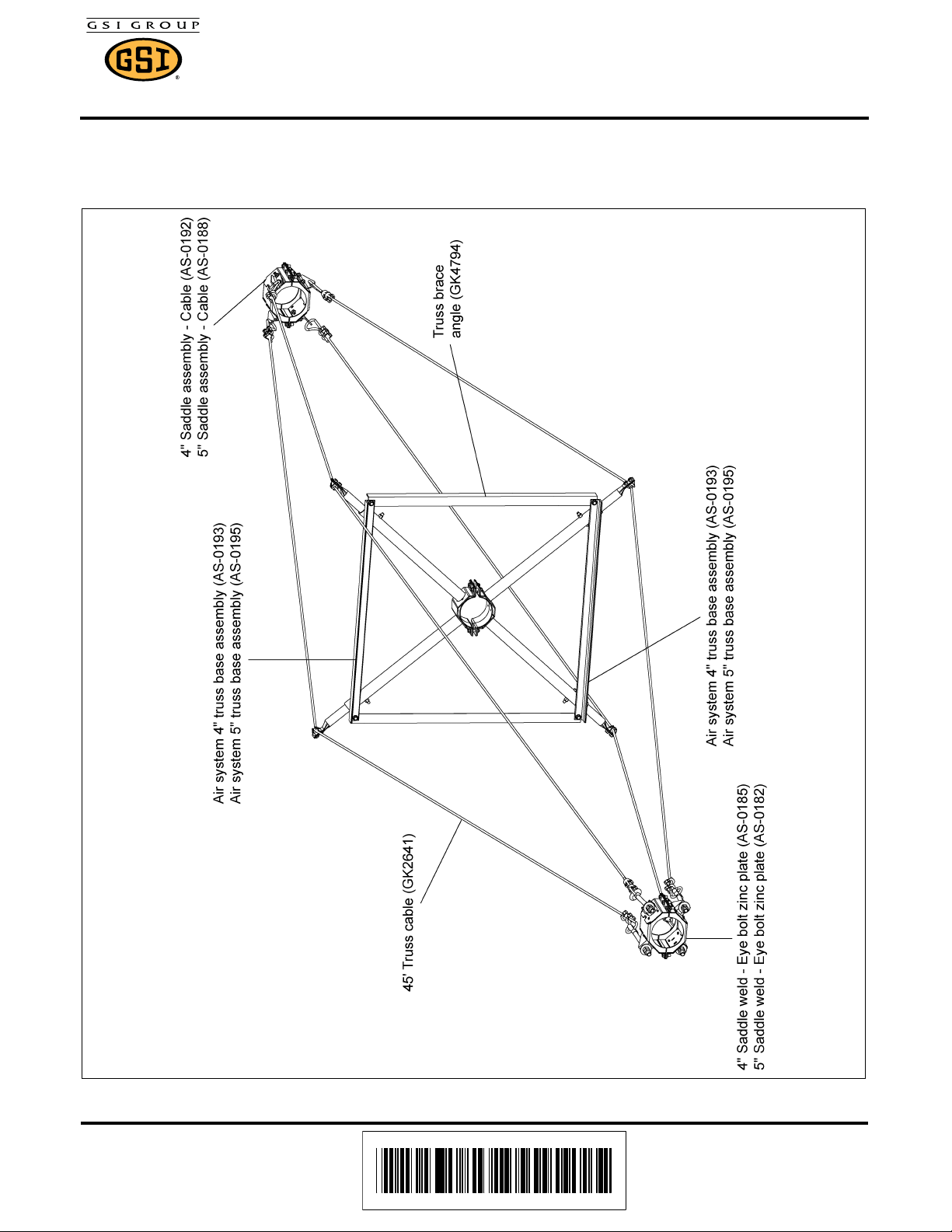
These truss kits are designed to provide support for air system tube sections up to 40' in length.
Figure 1
Date: 04-28-11 PNEG-1449
Printed in the U.S.A.
Copyright © 2011 by GSI Group
www.gsiag.com
Page 1 of 8
Page 2

4" and 5" Truss Kits for 40' Spans
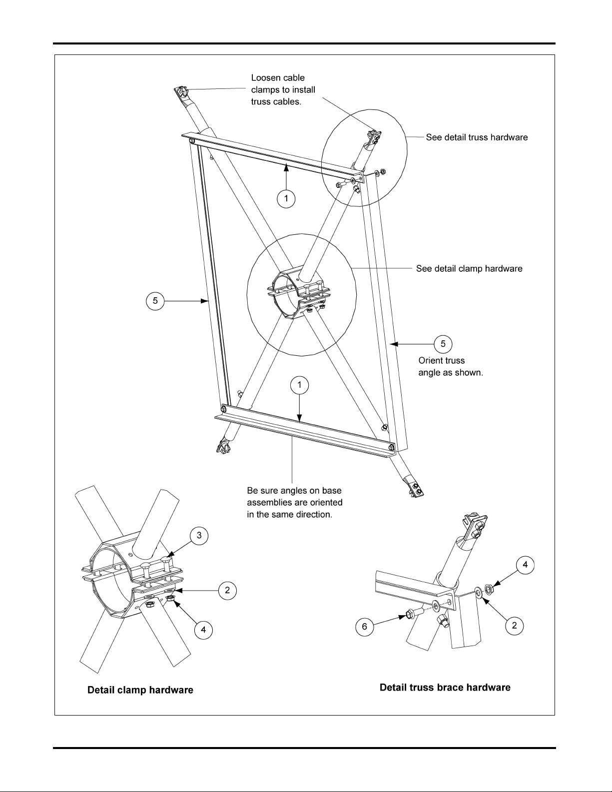
Step 1: Locate the truss base assemblies (Ref #1) in the center of the tube that is to be trussed as
shown in Figure 1 on Page 1. Be sure the angles on the base assemblies are oriented in the
same direction as noted. (See Figure 2 on Page 3.) Fasten the truss bases to the tube with
hardware Ref #2, #3 and #4. (See Figure 2 on Page 3.)
Step 2: Place truss braces (Ref #5) between the truss base assemblies and orient as shown. Attach
using hardware Ref #2, #4 and #6. (See Figure 2 on Page 3.)
Step 3: Position the cable saddle assemblies (Ref #11) and the eye bolt saddle weldments (Ref #7) on
opposite ends of the tube (See Figure 1 on Page 1) as close to the ends as possible but without
interfering with the compression couplers. Be sure to orient the saddle assemblies as shown in
Figure 3 on Page 4 and install with hardware Ref #4 and #6.
Step 4: Install the eye bolts (Ref #8) through the anchors on the eye bolt saddle weldments as shown in
Figure 3 on Page 4. Make sure the eye is pointing toward the center of the tube. Fasten the
eye bolts using hardware Ref #9 and #10. Leave hardware loose for later cable adjustment.
Step 5: Run cables through the chain connectors on the cable saddle assemblies and fasten with
two (2) 5/16" cable clamps (Ref #13) as shown in Figure 3 on Page 4.
NOTE: Secure the U-bolt of the clamps against the loose end of the cable.
Step 6: Loosen the 3/8" cable clamps on the tube base assemblies and route the cables through these
cable clamps to the eye bolt saddle weldments. DO NOT tighten 3/8" cable clamps at this time.
Step 7: Loop cables through eye bolts and fasten with two (2) 5/16" cable cla mps (Ref #13) as shown
in Figure 3 on Page 4.
NOTE: Secure the U-bolt of the clamps against the loose end of the cable.
Step 8:
Step 9: Tighten the 3/8" cable clamps that hold the cables to the tube base assemblies. Installation is
Using the eye bolts, tighten the cables to remove slack. Tighten all cables so they have the same
amount of tension.
adjustments are made, tighten the double 5/8" nuts (Ref #10) to lock the eye bolts in place.
now complete.
NOTE: Saddle assemblies should be skip welded to the tube to prevent slipping.
DO NOT
overtighten. Sight down the tube to make sure it is straight. Once
Page 2 of 8 PNEG-1449
Page 3
4" and 5" Truss Kits for 40' Spans
Figure 2 Installation of Tube Base Assemblies
PNEG-1449 Page 3 of 8
Page 4

4" and 5" Truss Kits for 40' Spans
Figure 3
Page 4 of 8 PNEG-1449
Page 5

4" and 5" Truss Kits for 40' Spans
Tube Truss Kits Parts List
Qty
Ref # Part # Description
4" 5"
1 AS-0193 Air System 4" Truss Base Assembly 2
1 AS-0195 Air System 5" Truss Base Assembly 2
2 S-248 Flat Washer 3/8" USS ZN YDP Grade 2 12 12
3 S-9082 Carriage Bolt 3/8"-16 x 2" ZN Grade 5 4 4
4 S-968 Flange Nut 3/8"-16 ZN Grade 5 20 20
5 GK4794 Truss Brace Angle 2 2
6 S-9065 Flange Bolt 3/8"-16 x 1" ZN Grade 5 16 16
7 AS-0185 4" Saddle Weld - Eye Bolt Zinc Plate 2
7 AS-0182 5" Saddle Weld - Eye Bolt Zinc Plate 2
8 S-10115 Eye Bolt 5/8"-11 x 13" Grade 2 ZN Weld 4 4
9 S-858 Flat Washer 5/8" USS ZN 4 4
10 S-7597 Hex Nut 5/8"-11 8 8
11 AS-0192 4" Saddle Assembly - Cable 2
11 AS-0188 5" Saddle Assembly - Cable 2
12 GK2641 Cable: Truss - 5/16" x 45' Long 4 4
13 GK2760 Clamp Cable 5/16" 16 16
PNEG-1449 Page 5 of 8
Page 6

4" and 5" Truss Kits for 40' Spans
Figure 4 Tube Base Assemblies
Tube Assembly Bases Parts List
Ref # Part # Description
1 AS-0177-RD Air System 4" Truss Base Weld - Red 1
1 AS-0176-RD Air System 5" Truss Base Weld - Red 1
2 GK4796 30" Truss Extension Tube 2 2
3 S-6762 Bolt, HHCS 3/8"-16 x 2-1/2" ZN Grade 5 2 2
4 S-7383 Nylock Nut 3/8"-16 ZN Grade 5 2 2
5 GK2759 Clamp Cable Assembly 3/8" 2 2
Page 6 of 8 PNEG-1449
Qty
4" 5"
Page 7

PNEG-1449 Page 7 of 8
NOTES
Page 8

This equipment shall be installed in accordance with
the current installation codes and applicable
regulations which should be carefully followed in all
cases. Authorities having jurisdiction should be
consulted before installations are made.
Copyright © 2011 by GSI Group
Printed in the USA
GSI Group
1004 E. Illinois St.
Assumption, IL 62510-0020
Phone: 1-217-226-4421
Fax: 1-217-226-4420
www.gsiag.com
 Loading...