

Page 1
Parts
Manual
1200S Network Series
Portable Dryers
PNEG-1447
Date: 09-22-10
PNEG-1447
Page 2

Page 3

Table of Contents
MAIN STRUCTURE ASSEMBLY...................................................................................5
FRAME ASSEMBLY..............................................................................................................................................................5
FRAME, LOWER BASKET, AND METERING ROLLS......................................................................................................8
PLENUM (INSIDE) SCREENS AND METER ROLL UPPER SHIELD.............................................................................12
OUTER SCREENS AND PLENUM DIVIDER...................................................................................................................14
CLEAN OUT DOORS...........................................................................................................................................................16
FRONT AND REAR PLENUM END PANELS AND REAR ACCESS DOORS................................................................18
LADDER ASSEMBLIES......................................................................................................................................................20
BOTTOM AUGER...............................................................................................................................................................22
TOP AUGER WITH WET BIN............................................................................................................................................24
AUGER AND METER ROLL DRIVE TRAINS..............................................................26
BOTTOM AUGER DRIVE..........................................................................................................................................................26
TOP AUGER DRIVE...........................................................................................................................................................28
METER ROLL DRIVE........................................................................................................................................................30
FAN HEATERS.................................................................................................................32
FAN HOUSING ASSEMBLIES.................................................................................................................................................32
FAN MOTOR, MOTOR MOUNT, AND FAN BLADE................................................................................................................34
AIR MIXERS........................................................................................................................................................................35
FLAME PROBE, IGNITOR, AND BURNER ASSEMBLIES..............................................................................................36
LP PIPE TRAIN ASSEMBLIES...........................................................................................................................................38
NG PIPE TRAIN ASSEMBLIES..........................................................................................................................................44
FAN HEATER ORIFICES.............................................................................................................................................47
LP SUPPLY LINE.......................................................................................................................................................48
NG SUPPLY LINE.......................................................................................................................................................49
DRYER ELECTRICAL CONDUITS..................................................................................50
RIGHT AND LEFT GRAIN, AND PLENUM HIGH LIMITS.......................................................................................50
LOWER JUNCTION BOXES, METER ROLL MOTOR CONDUIT, AND REAR DISCHARGE CONDUIT.................52
UPPER JUNCTION BOX, TOP AUGER MOTOR CONDUIT, AND OPERATOR LIGHT...........................................54
AIR SWITCH ASSEMBLY............................................................................................................................................55
CONTROL BOXES..........................................................................................................56
NETWORK CONTROL BOX......................................................................................................................................56
FAN HEATER CONTROL BOX..................................................................................................................................58
LOWER CONTROL BOX CONTROL PANEL...........................................................................................................60
LOWER CONTROL BOX CONTROL PANEL (INSIDE)............................................................................................61
LOWER CONTROL BOX BACK PANEL...................................................................................................................62
UPPER CONTROL BOX.............................................................................................................................................63
NOTES................................................................................................................................67
PNEG-1447
3
Page 4

4
PNEG-1447
Page 5
Frame
5 3
3
55 3
4a
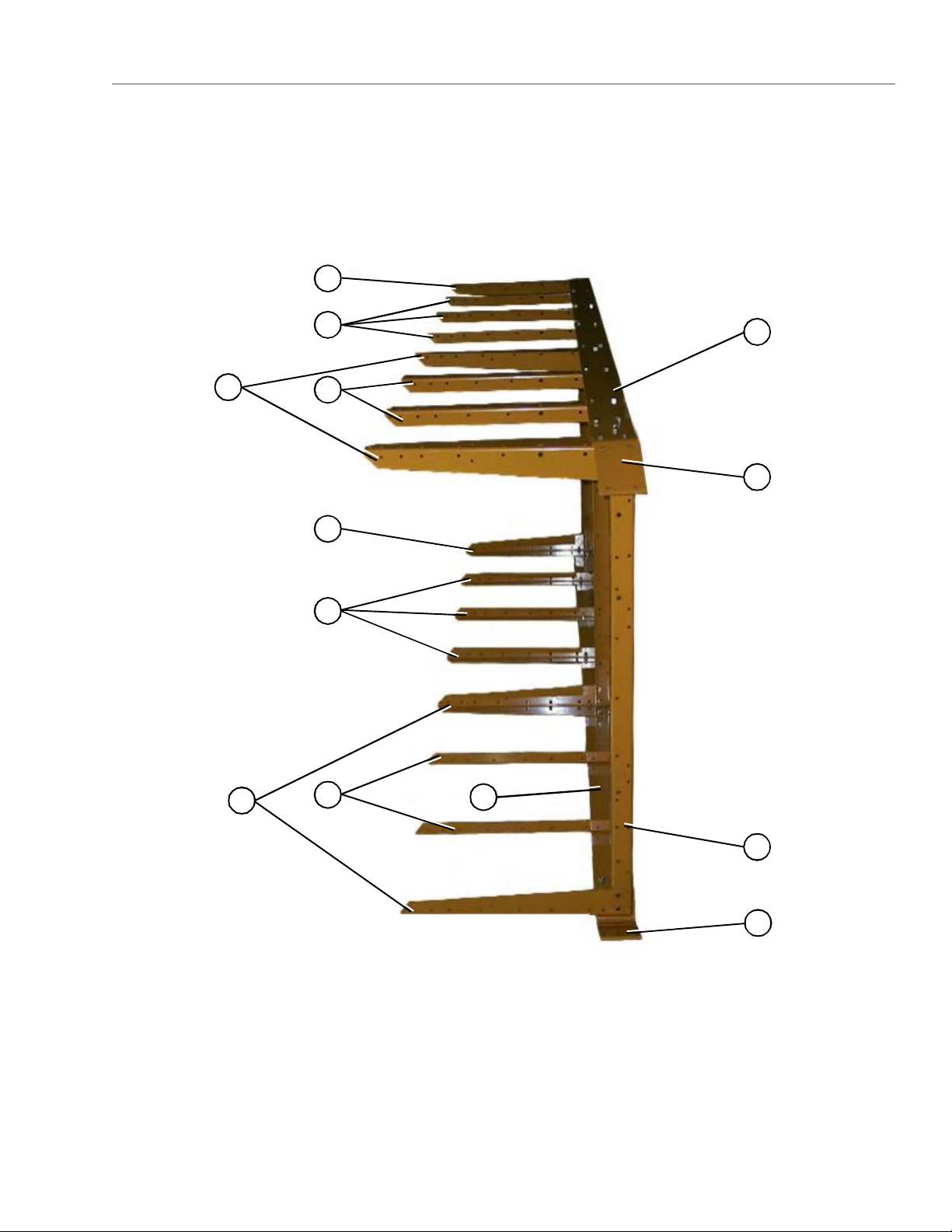
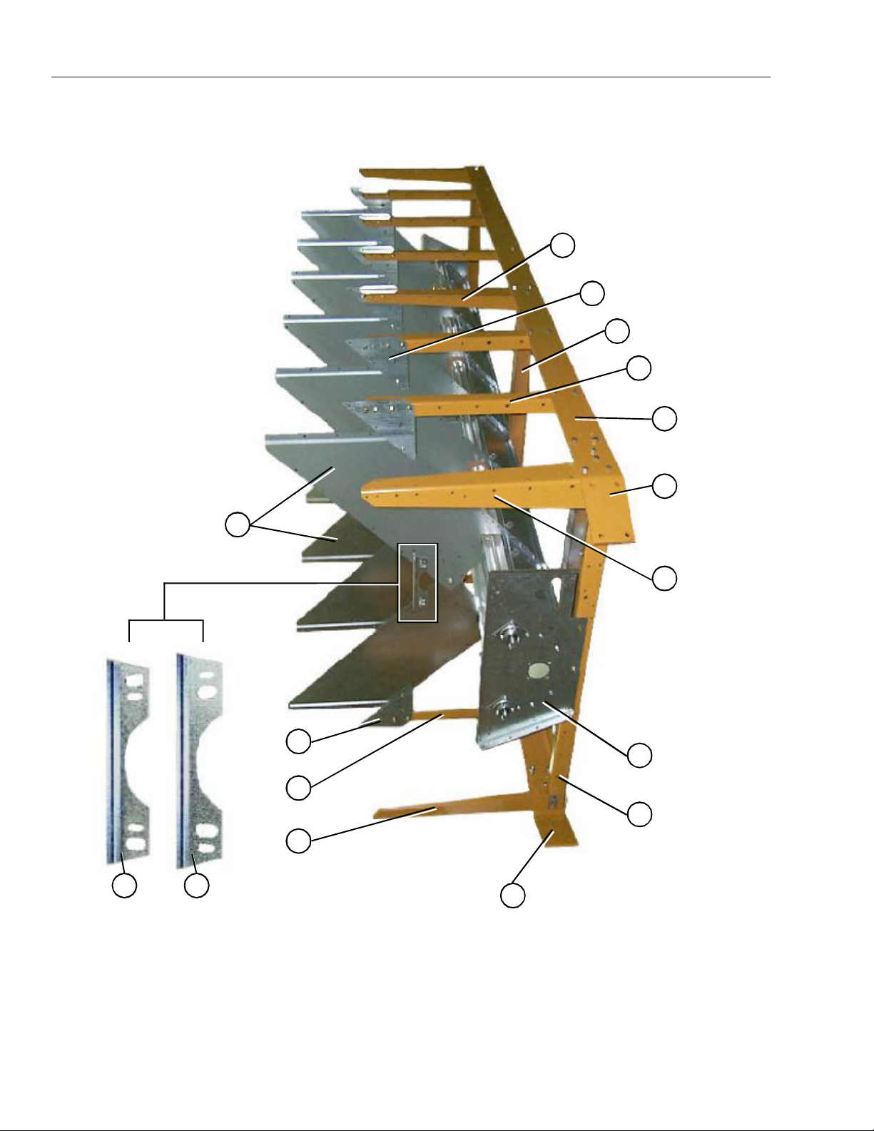
Frame Assembly (view from fan/heater end with hitch weldment removed).
PNEG-1447
3
5
4
Right side Left side
**NOTE: The parts pointed out on this page are listed on page 7.
2 1a
1
The fan heater end of the dryer is considered by GSI as the front end of the dryer (the
foreground of this photograph is the front end. Right and left sides are labeled above).
5
Page 6
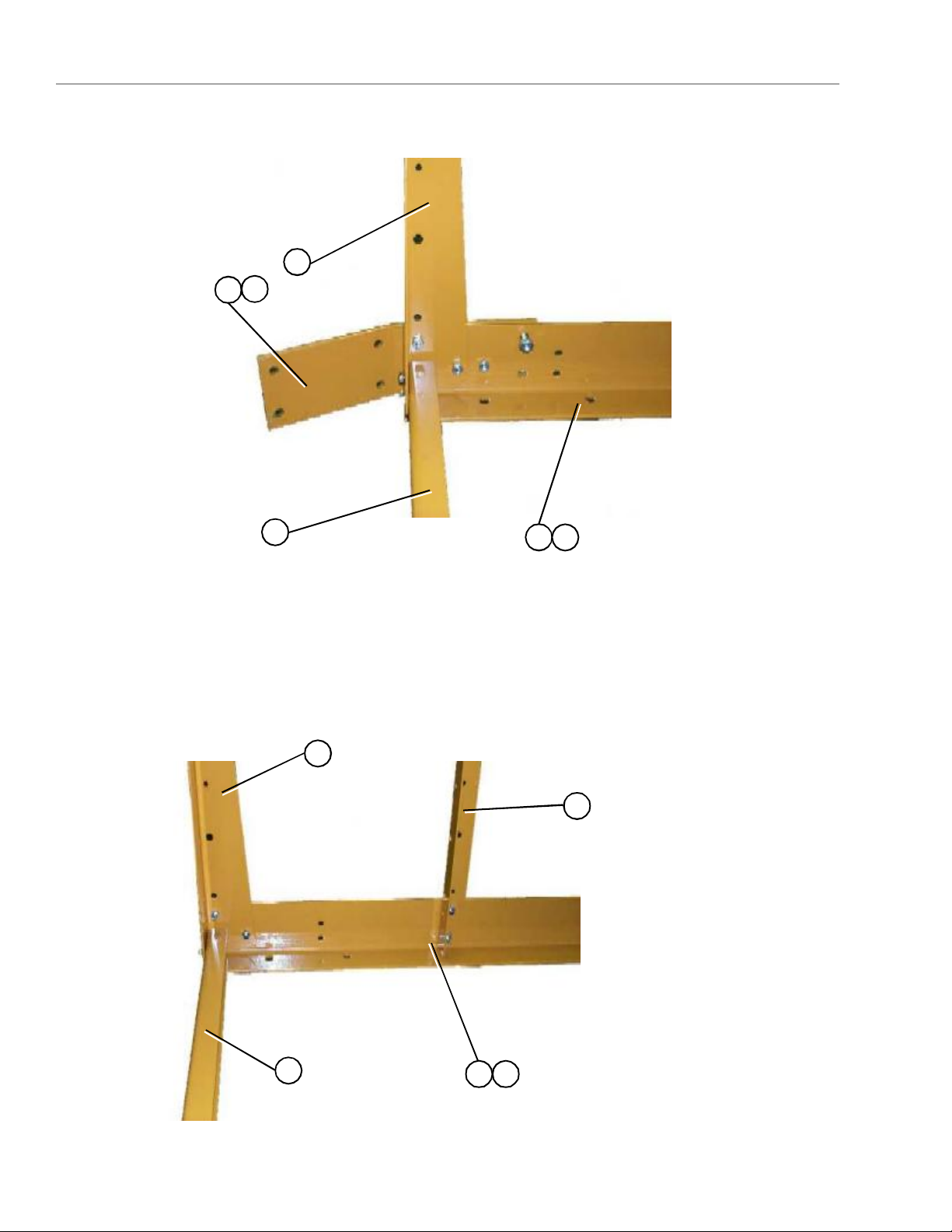
Right front corner of frame.
3
1
1a
Frame
**NOTE: The right front corner
is shown in the photo. For left
front corner all parts are the
same except for the Hitch
Bracket (use 1a for the left side),
and the Frame Rail (use 4a for
the left side).
2
Left rear corner of frame.
3
4
4a
5
**NOTE: The left rear corner is
shown in the photo. For right
rear corner all parts are the same
2
4a
4
except for the Frame Rail (use 4
for the right side).
6
PNEG-1447
Page 7
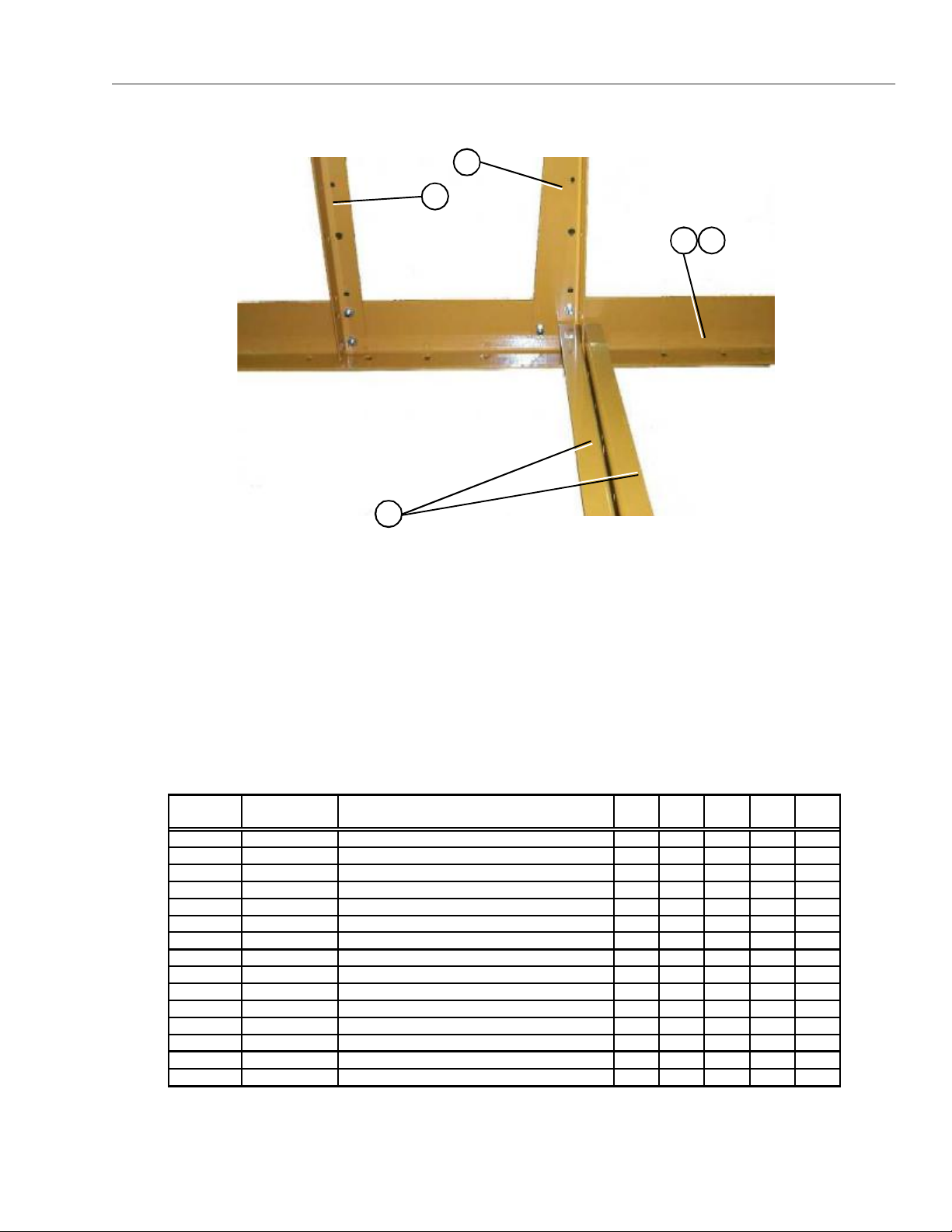
Center cross ties.
ITEM
Frame
3
5
4 4a
2
NUMBERPART NUMBER
PNEG-1447
DESCRIPTION1214S1218S1220S1222S1226S
1D01-0012HITCH BRACKET RIGHT11111
1aD01-0011HITCH BRACKET LEFT11111
2D01-0008FRONT & REAR FRAME TIE CHANNEL44466
3D01-0007CORNER LEG PORTABLE DRYER66688
4D21-0011FRAME RAIL, 14' RIGHT1
4aD21-0010FRAME RAIL, 14' LEFT1
4D31-0044FRAME RAIL, 18' RIGHT1
4aD31-0043FRAME RAIL, 18' LEFT1
4D61-0002FRAME RAIL, 20' RIGHT1
4aD61-0001FRAME RAIL, 20' LEFT1
4D101-0002FRAME RAIL, 22' RIGHT1
4aD101-0001FRAME RAIL, 22' LEFT1
4D71-0001FRAME RAIL, 26' RIGHT1
4aD71-0002FRAME RAIL, 26' LEFT1
5D01-0005SIDE LEG PORTABLE DRYER1014161620
7
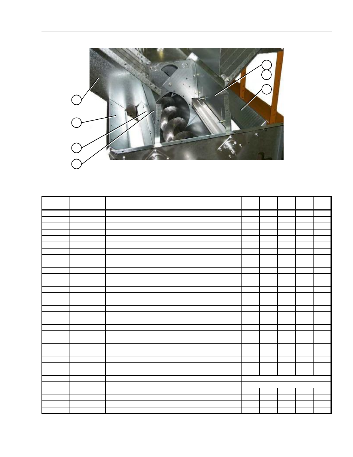
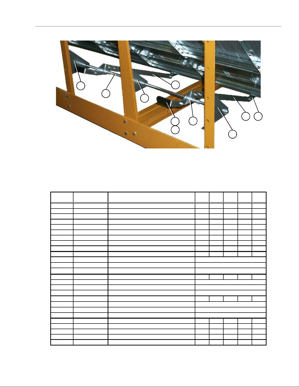
Page 8
Frame, Auger Trough, & Hopper Bulkheads
6
4
9
5
8 116
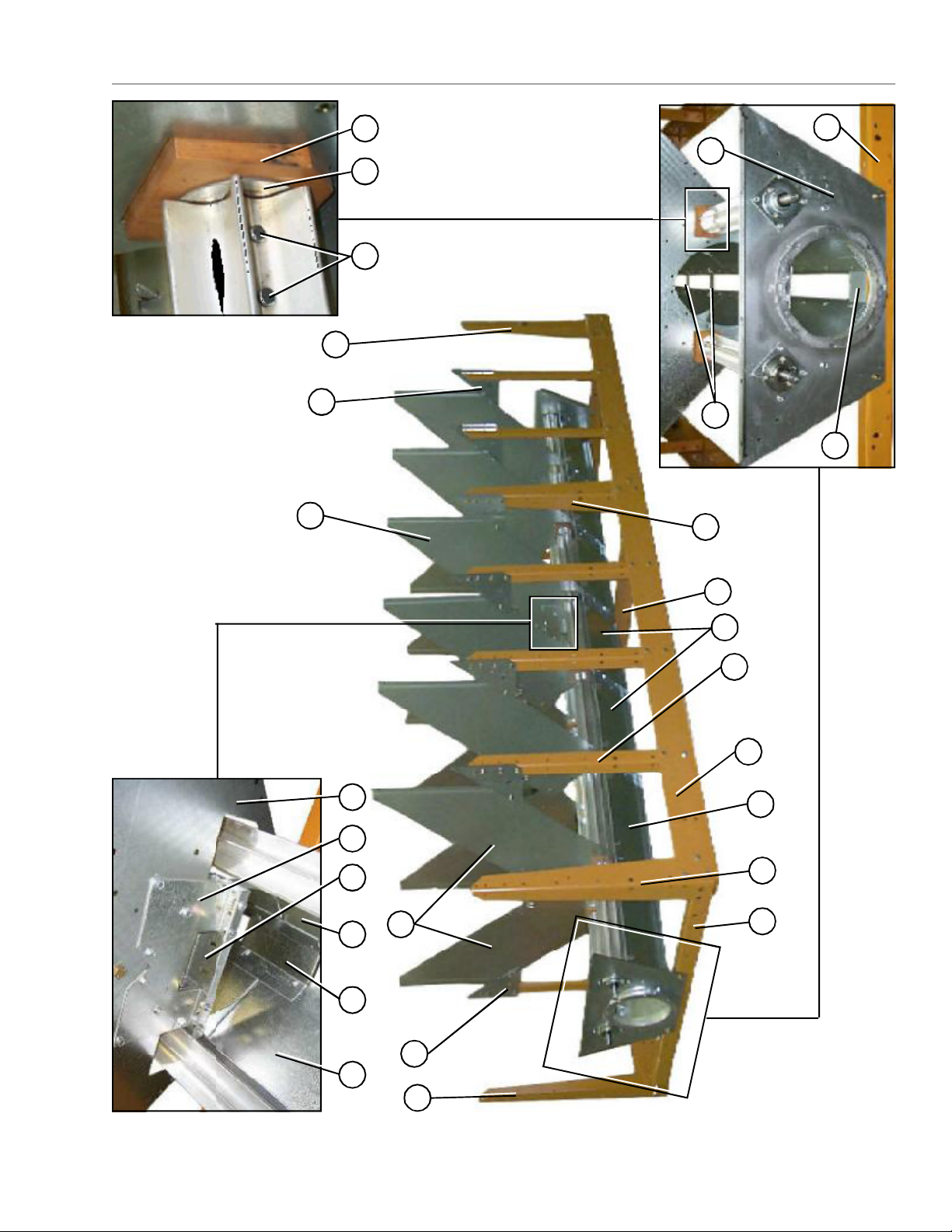
Dryer frame and lower basket assembly (view from the
front end of the dryer looking down the left side).
3
56 4
9 10
1
2
7
L.H. and R.H.
the plenum closure
distinguish between
door angles. This will
Note the hole pattern of
**NOTE: The parts pointed out on this page are listed on page 11.
8
PNEG-1447
Page 9
Frame, Auger Trough, & Hopper Bulkheads
181716
9
21
6
assembly.
4
19
20
shaft (part no. D31-0046) that
together with a meter roll splice
The meter roll sections are spliced
Wooden meter roll support bearing.
passes through the support bearing
3
Discharge bearing plate.
6
9
12
5
11a
Center hanger bearing support
and cross channel seal plate.
12
3
9 6
PNEG-1447
4
12 13 12 14 15 3
6
**NOTE: The parts pointed out on this page are listed on page 11.
Dryer frame and lower basket assembly (view from the
rear end of the dryer looking up the right side).
9
Page 10
Metering Rolls and their placement in the dryer.
NOTE: Item 22 at the rear of
dryer is a front section meter
roll that is used as a rear section
on 16 and 20 foot dryers only.
Meter Rolls and Their Placement in the Dryer
22
24
Meter Roll Bearing
See pg. 11
Items 16, 17, 18
23
23
13
19
23
Meter Roll Bearing
See pg. 11
Items 16, 17, 18
23
Meter Roll Bearing
See pg. 11
Items 16, 17, 18
10
19
22
22
This end is the front (fan/heater) end of the dryer.
PNEG-1447
Page 11

Meter Rolls and Their Placement in the Dryer
ITEM
NUMBERPART NUMBER
1D01-1136YPLENUM CLOSURE DOOR ANGLE, RH6891012
2D01-1136XPLENUM CLOSURE DOOR ANGLE, LH79101113
3D01-0109HOPPER BULKHEAD1216182024
4D01-0004GUSSET PLATE1620222428
5D01-0005SIDE LEG1014161620
6D01-0007CORNER LEG66688
7D01-0011HITCH BRACKET, LH11111
8D01-0012HITCH BRACKET, RH11111
9D01-0008FRONT & REAR FRAME TIE CHANNEL44466
10D01-2435Front Bearing Plate 200811111
11D21-0011FRAME RAIL, 14' RIGHT1
11D31-0044FRAME RAIL, 18' RIGHT1
11D61-0002FRAME RAIL, 20' RIGHT1
11D101-0002FRAME RAIL, 22' RIGHT1
11D71-0001FRAME RAIL, 26' RIGHT1
11AD21-0010FRAME RAIL, 14' LEFT1
11AD31-0043FRAME RAIL, 18' LEFT1
11AD61-0001FRAME RAIL, 20' LEFT1
11AD101-0001FRAME RAIL, 22' LEFT1
11AD71-0002FRAME RAIL, 26' LEFT1
12D01-0048TROUGH PANEL1418202226
13D01-1512PLATE, CROSS CHANNEL SEAL W/TABS11122
14D01-1291HANGER BEARING "C" CHANNEL 11122
15D01-1290HANGER BEARING "J" PLATE22244
16D02-0028CLEVIS PIN 5/16" x 1 3/4" 3240404856
17D31-0148METER ROLL WASHER1620202428
18D02-0061METER ROLL SUPPORT BEARING6881012
19D01-0177SUPPORT STRAP79101113
20D01-1511PLATE, END CHANNEL SEAL W/TAB22222
21D01-2434DISCHARGE PLATE 200811111
22D31-0031METER ROLL, FRONT22422
23D31-0030METER ROLL, INTERMEDIATE466810
24D31-0029METER ROLL, REAR22 22
DESCRIPTION1214S1218S1220S1222S1226S
PNEG-1447
The part number list above covers all parts pointed out on pages 8, 9, and 10.
11
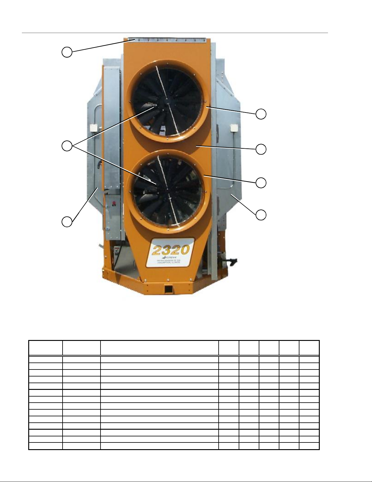
Page 12
Inside (Plenum) Screens, Plenum Closure Doors
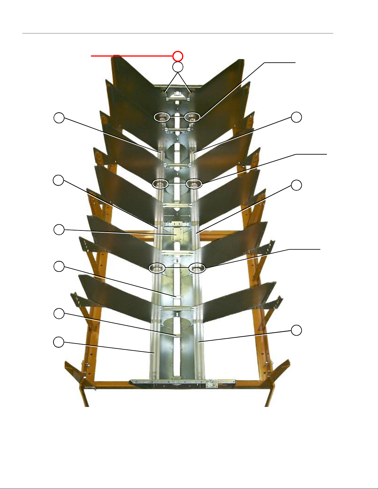
Plenum screens and bulkheads (view from front end).
3
4
3
5
6
12
5
16
7
8
10
11
13
14
18
19
12
9
10
7
15
This photograph was taken before the front
plenum end panel and outer screens where
installed in order to get a good view of the inside
20
20a
screens and bulkheads.
12
22
21
Plenum closure door. There are two different plenum closure doors. The door
shown in the photogragh is the rear plenum closure door and is the rear most
plenum closure door, item no. 20 (just inside the rear access door), all others
are item no. 20a. NOTE: Item 22 is the plenum closure door rear frame angle.
PNEG-1447
Page 13
Meter Roll Upper Shield Assembly
ITEM
Close up of of meter roll upper shield assembly.
16
17
18
19
19
18
17
NUMBERPART NUMBER
1D31-0055COLUMN BULK HEAD1216182024
2D01-0101GARNER BULKHEAD1216182024
3D31-0307COLUMN END PANEL44444
4D01-0126SCREEN,PLENUM TOP,GA,0941418202226
5D31-0012SCREEN,PLENUM WALL,GA,0941418202226
6D01-1225SCREEN,PLENUM BOTTOM,GA,0941418202226
7D01-0004GUSSET PLATE1620222428
8D21-0011FRAME RAIL, 14' RIGHT1
8D31-0044FRAME RAIL, 18' RIGHT1
8D61-0002FRAME RAIL, 20' RIGHT1
8D101-0002FRAME RAIL, 22' RIGHT1
8D71-0001FRAME RAIL, 26' RIGHT1
9D21-0010FRAME RAIL, 14' LEFT1
9D31-0043FRAME RAIL, 18' LEFT1
9D61-0001FRAME RAIL, 20' LEFT1
9D101-0001FRAME RAIL, 22' LEFT1
9D71-0002FRAME RAIL, 26' LEFT1
10D01-0007CORNER LEG PORTABLE DRYER66688
11D01-0012HITCH BRACKET RIGHT11111
12D01-0011HITCH BRACKET LEFT11111
13D01-0008FRONT & REAR FRAME TIE CHANNEL44466
14D01-2435Front Bearing Plate 200811111
15D01-0005SIDE LEG PORTABLE DRYER1014161620
16D01-0109HOPPER BULKHEAD1216182024
17D01-0050PCONNECTOR SHEET, PERFORATED1418202226
*18&19D01-1180METER ROLL UPPER SHIELD ASSY.1418202226
18D01-0431METER ROLL STRIKE OFF PLATE
19D01-1226METER ROLL SHIELD 1995 STYLE
20D01-1214PLENUM CLOSURE DOOR, REAR11111
20aD01-1134PLENUM CLOSURE DOOR 6891012
21DC-974DANGER FOOT IN AUGER DECAL22222
22D01-1217PLENUM CLOSURE DOOR REAR FRAME ANGLE11111
*ITEM NUMBERS 18 AND 19 TOGETHER MAKE UP THE METER ROLL UPPER SHIELD ASSEMBLY
DESCRIPTION1214S1218S1220S1222S1226S
1 PER ASSEMBLY
1 PER ASSEMBLY
PNEG-1447
13
Page 14
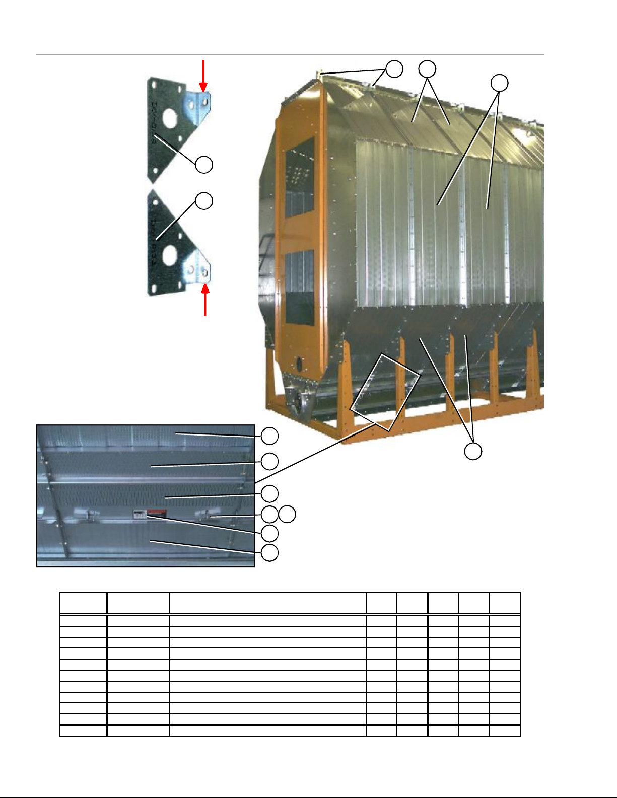
Outside Screens / Meter Roll Access Door
ITEM
*Note: Item 4 is pointing to
the top edge angle gusset.
There are two types of gusset
on the dryer. The photo right
will help distinguish the
difference between the two.
The arrows are pointing to a
tab on the gusset that makes
them different (tabs are
“bent” up in photo). Item 4a
is used in two places only; 1.)
front right of dryer 2.) rear
left of dryer, all others are
item 4.
4a
4
*
1
2
4
Meter roll access door.
NUMBERPART NUMBER
1D01-0127SCREEN,ROOF,GA,0941418202226
2D31-0013SCREEN,OUTSIDE WALL,GA,0941418202226
3D01-0128SCREEN,HOPPER,GA,0941418202226
4D01-0152LH TOP ANGLE GUSSET1216182024
4aD01-0153RH TOP ANGLE GUSSET22222
5D01-0050PCONNECTOR SHEET, PERFORATED1418202226
6D01-0045PACCESS DOOR, PERFORATED1418202226
7D01-0039DOOR LATCH2836404452
8S-6552PIN HAIR CLIP 3/32 ZN PLATED2836404452
9DC-1229DECAL, WARNING METER ROLL ROT.1418202226
10D01-0048TROUGH PANEL WELDMENT1418202226
3
3
5
6
8
7
9
10
DESCRIPTION1214S1218S1220S1222S1226S
14
PNEG-1447
Page 15
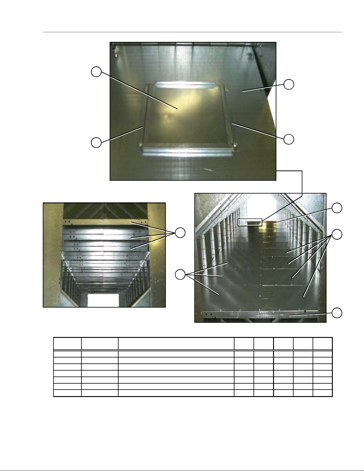
Plenum Divider
ITEM
Right rear plenum divider section with clean-out door.
1
3
2
Plenum divider support channels.
Plenum divider floor sections.
4
5
2
7
6
NUMBERPART NUMBER
1D31-0259PLENUM DIVIDER CLEAN-OUT DOOR11111
2D31-0260CLEAN-OUT DOOR GUIDE PLENUM22222
3D61-0028PLENUM DIVIDER RH: REAR11111
4D61-0024PLENUM SUPPORT CHANNEL810111214
5D61-0026PLENUM DIVIDER RH6891012
6D61-0025PLENUM DIVIDER LH6891012
7D61-0027PLENUM DIVIDER LH: REAR11111
DESCRIPTION1214S1218S1220S1222S1226S
NOTE: The quantities listed for the parts above are for one module only. The plenum divider components
shown are the same for both modules.
PNEG-1447
4
15
Page 16
Clean Out Doors
Front and rear handle mechanisms (rear shown in photo).
1
3
2
4
5
13
*Note: Items 9, 10, & 11 together create the
clean out door assembly. There are three
different clean out door assemblies that are used
on GSI Network dryers:
1.) 3 column clean out door assy. (D51-0077).
Item 8a on the part no. listing (pg 17).
2.) 4 column clean out door assy. (D11-0032).
Item 8b on the part no. listing (pg 17).
3.) 5 column clean out door assy. (D01-0349).
Item 8c on the part no. listing (pg 17).
A 5 column clean out door assy (D01-0349) is
shown in the photograph below.
11
Clean out door handle mechanism.
4
3
3a
2
Clean out door hinge.
5
9
6
7
11
10
16
9
11
10
12
13
11
PNEG-1447
Page 17
Clean Out Doors
ITEM
Center handle mechanisms (this handle mechanism stradles the center cross channels).
14
3a
1a
14
3a 11
4
2
5
14
NUMBERPART NUMBER
1D01-0264PIVOT ROD 25.188"22222
1aD31-0162PIVOT ROD 49.625"11122
2D01-0296LINKAGE BAR WELDMENT44466
3D01-0261LINKAGE BAR, 37" LONG22222
3aD01-0293LINKAGE BAR, 30" LONG22244
4D01-0294CLEAN OUT DOOR HANDLE44466
5S-4378PLASTIC GRIP44466
6S-248WASHER, FLAT 3/8 USS ZN 8881212
7S-7241COTTER PIN, 1/8 x 1 1/48881212
8aD51-0077CLEAN OUT DOOR ASSY, 3 COLUMN11
9D21-0005CLEAN OUT DOOR, 67"
10D21-0012SUPPORT CHANNEL, CLEAN OUT DOOR
11D01-0308CLEAN OUT DOOR HINGE
8bD11-0032CLEAN OUT DOOR ASSY, 4 COLUMN1122
9D31-0021CLEAN OUT DOOR, 91"
10D31-0130SUPPORT CHANNEL, CLEAN OUT DOOR
11D01-0308CLEAN OUT DOOR HINGE
8cD01-0349CLEAN OUT DOOR ASSY, 5 COLUMN121
9D01-0180CLEAN OUT DOOR, 115"
10D01-0307SUPPORT CHANNEL, CLEAN OUT DOOR
11D01-0308CLEAN OUT DOOR HINGE
12D01-0175HINGE BRACKET45667
13D01-0181CLEAN OUT EXTENSION, 119.75"242
13D31-0023CLEAN OUT EXTENSION, 90.75"2244
13D21-0006CLEAN OUT EXTENSION, 66.75"22
14D01-0299PIVOT ROD BRACKET33366
DESCRIPTION1214S1218S1220S1222S1226S
1 PER ASSEMBLY
1 PER ASSEMBLY
2 PER ASSEMBLY
1 PER ASSEMBLY
1 PER ASSEMBLY
2 PER ASSEMBLY
1 PER ASSEMBLY
1 PER ASSEMBLY
3 PER ASSEMBLY
PNEG-1447
17
Page 18
Front End Panels / Fan Support / grill guards
1
5
2
4
5
3
3
ITEM
NUMBERPART NUMBER
1D61-0023TOP ANGLE, FAN SUPPORT PANEL11111
2CD-0576GRILL GUARD: CD-28 BLACK2
2CD-0544GRILL GUARD: 36" BLACK222
2CD-0547GRILL GUARD: 40&42" BLACK2
3D31-0307COLUMN END PANEL44444
4D01-0593FRONT FAN SUPPORT 2-28"1
4D61-0041FRONT FAN SUPPORT 2-36"111
4D71-0008FRONT FAN SUPPORT 2-40"1
5F-7060-YVENTURI: 28" YEL/OCHRE2
5CD-0543-YVENTURI: 36" OCHRE222
5CD-0545-YVENTURI: 40" OCHRE2
NOT SHOWND01-0594FRONT END PANEL 2-28"1
NOT SHOWND61-0018FRONT END PANEL 2-36"111
NOT SHOWND71-0006FRONT END PANEL 2-40"1
18
DESCRIPTION1214S1218S1220S1222S1226S
PNEG-1447
Page 19
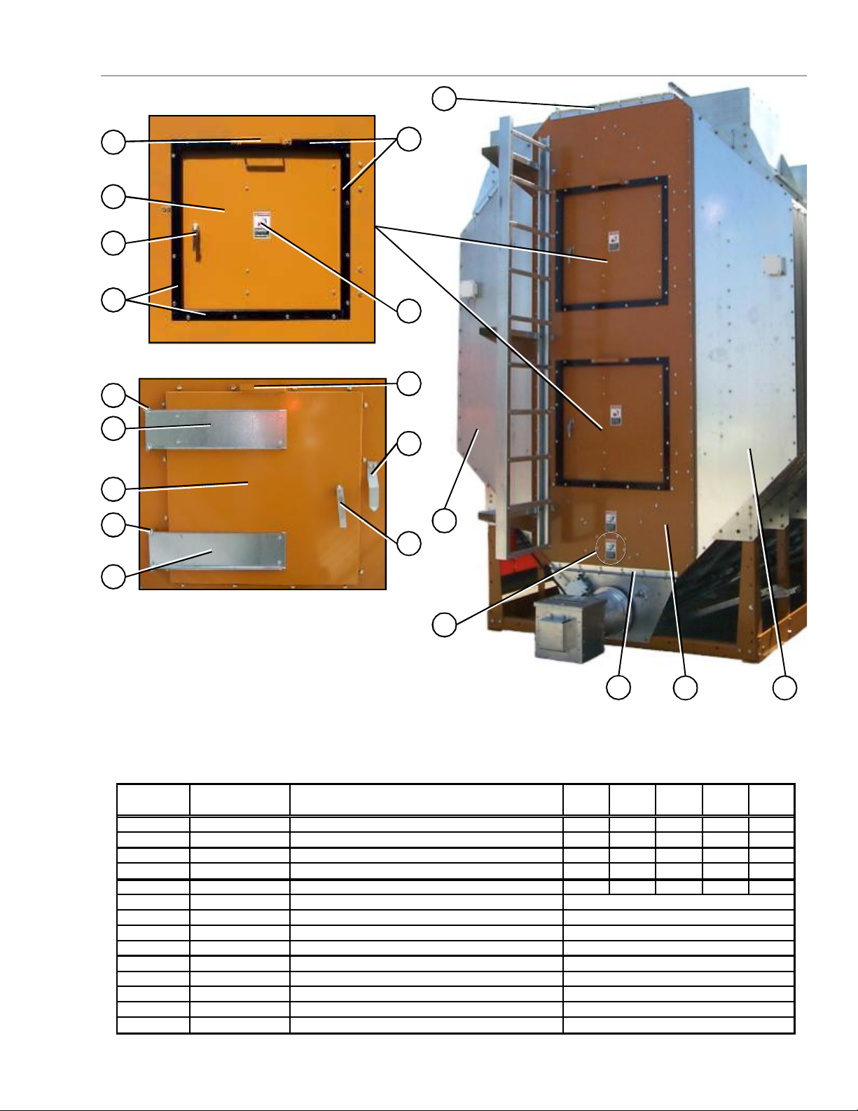
Rear End Panels / Rear Access Door
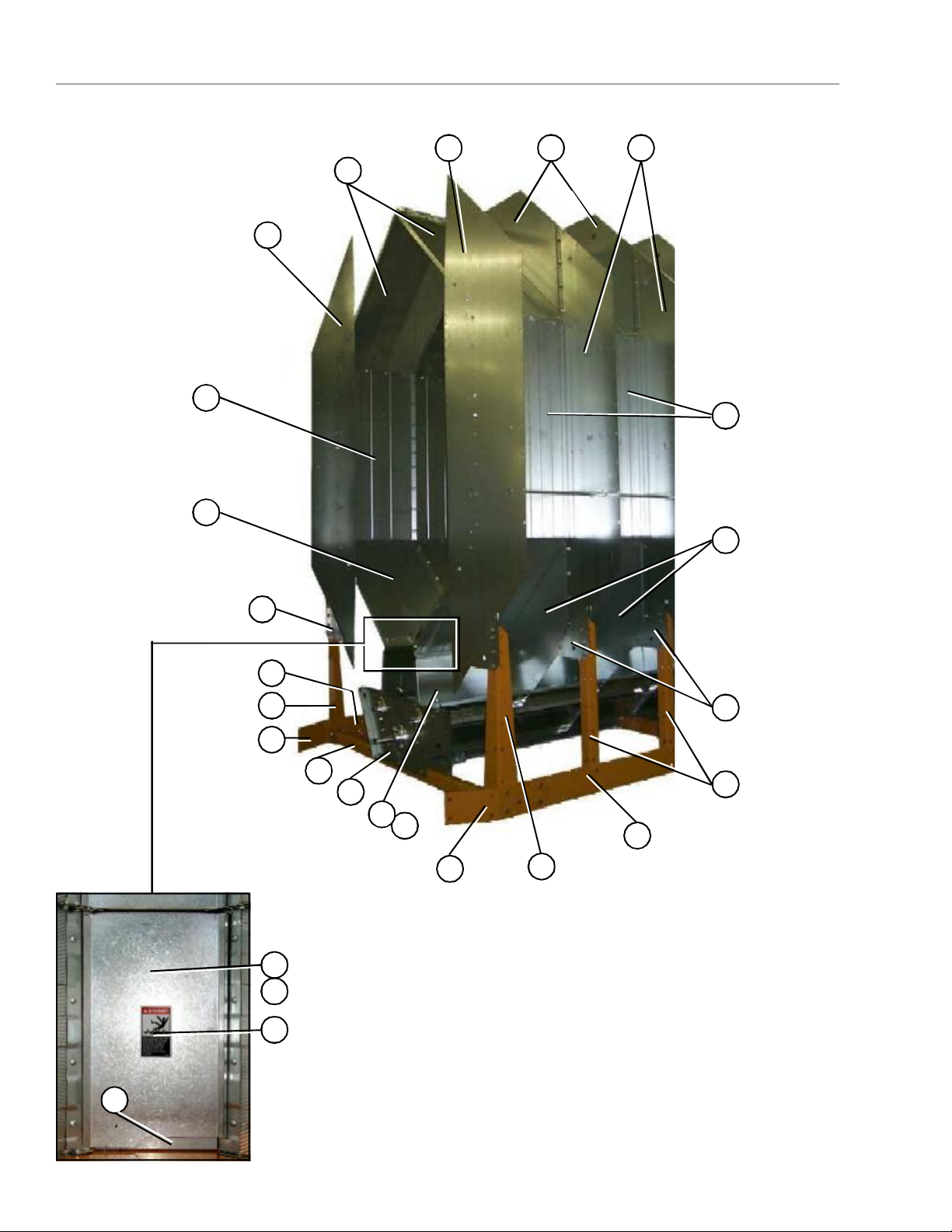
Rear access door (outside).
5
6
7
8
Rear access door (inside).
10
11
6
3
8
9
5
12
10
1
13
11
4
3
ITEM
NUMBERPART NUMBER
1D31-0307COLUMN END PANEL44444
2D01-1800-YREAR END PANEL 50/50 29" DOORS11111
3D01-0044TOP ANGLE BRACKET FRONT & REAR33333
4D01-1510ASPIRATOR END CAP11111
5-13RDA-29-YREAR DOOR ASSEMBLY 29"SQ OCHR22222
5D01-1783-YASSIST HANDLE 29" SQ. DOOR
6D01-1781-YDOOR 29" SQUARE OCHRE
7D03-0512DOOR HANDLE,LOCKING CCW
8D01-1782-BLKFRAME ANGLE 29" DOOR
9DC-973DECAL, DANGER FIRE HAZARD
10401-4630-0HINGE BRACKET-SQUARE DOOR
11401-4669-8HINGE-REAR ACCESS SQ DOOR
12D01-0397LATCH BRACKET
13D01-1792LATCH BAR 29" SQUARE DOOR
DESCRIPTION1214S1218S1220S1222S1226S
2 1
2/ASSEMBLY
1/ASSEMBLY
1/ASSEMBLY
4/ASSEMBLY
2/ASSEMBLY
2/ASSEMBLY
2/ASSEMBLY
1/ASSEMBLY
1/ASSEMBLY
PNEG-1447
19
Page 20
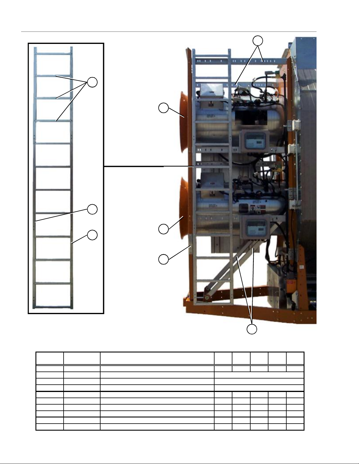
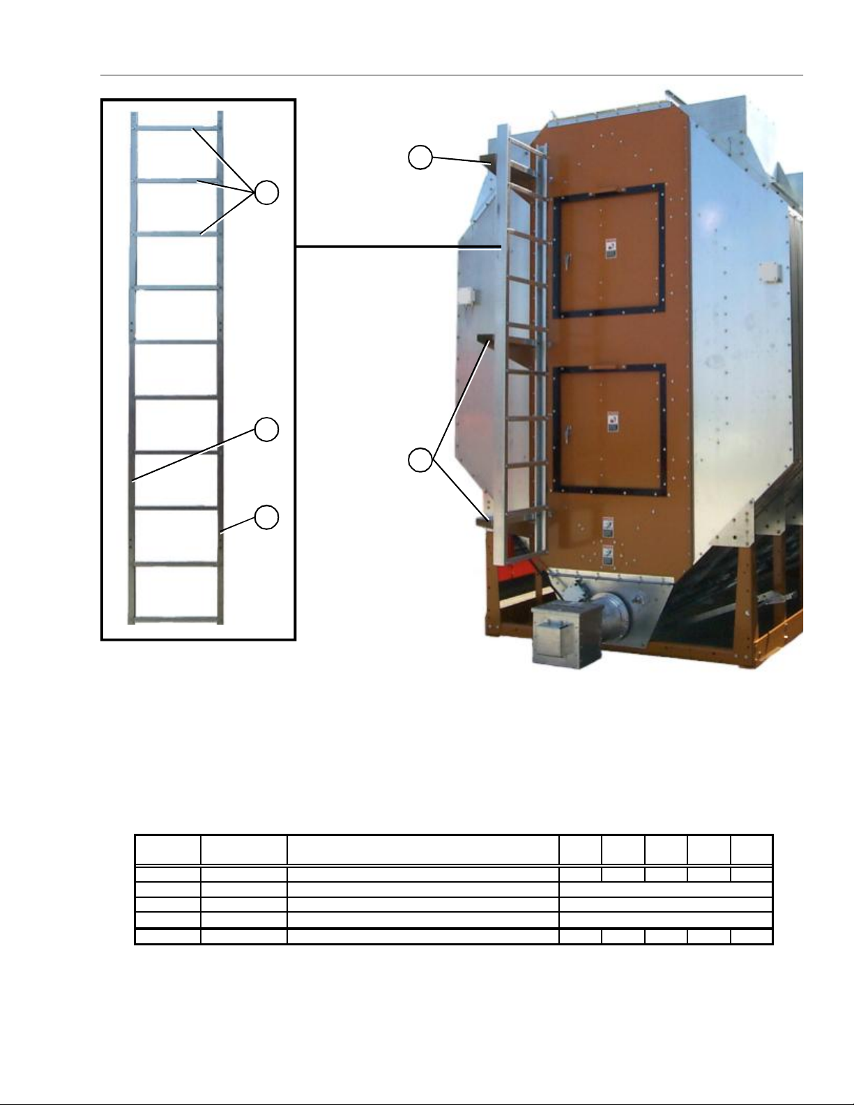
Front Ladder Assembly
ITEM
4
1
5
2
5
3
6
7
NUMBERPART NUMBER
1-3D01-1220LADDER ASSY. STACK DRYER FRONT11111
1D61-0096LADDER RUNG
2D61-0094LADDER SIDE RAIL-LH
3D61-0095LADDER SIDE RAIL-RH
4D51-0022SUPPORT, CONTROL PANEL77777
5F-7060-YVENTURI: 28" YEL/OCHRE2
5CD-0543-YVENTURI: 36" OCHRE222
5CD-0545-YVENTURI: 40" OCHRE2
6D51-0021STIFFENER, FRONT FAN SUPPORT22222
7D31-0082FRONT DIAGONAL SUPPORT CHANNEL22222
DESCRIPTION1214S1218S1220S1222S1226S
12/ASSEMBLY
1/ASSEMBLY
1/ASSEMBLY
20
PNEG-1447
Page 21
Rear Ladder Assembly
ITEM
4
1
2
4
3
NUMBERPART NUMBER
1-3D04-0388LADDER ASSEMBLY11111
1D61-0096LADDER RUNG
2D61-0092LADDER SIDE RAIL-LH
3D61-0093LADDER SIDE RAIL-RH
4D61-0097LADDER MOUNTING BRACKET, REAR33333
DESCRIPTION1214S1218S1220S1222S1226S
10/ASSEMBLY
1/ASSEMBLY
1/ASSEMBLY
PNEG-1447
21
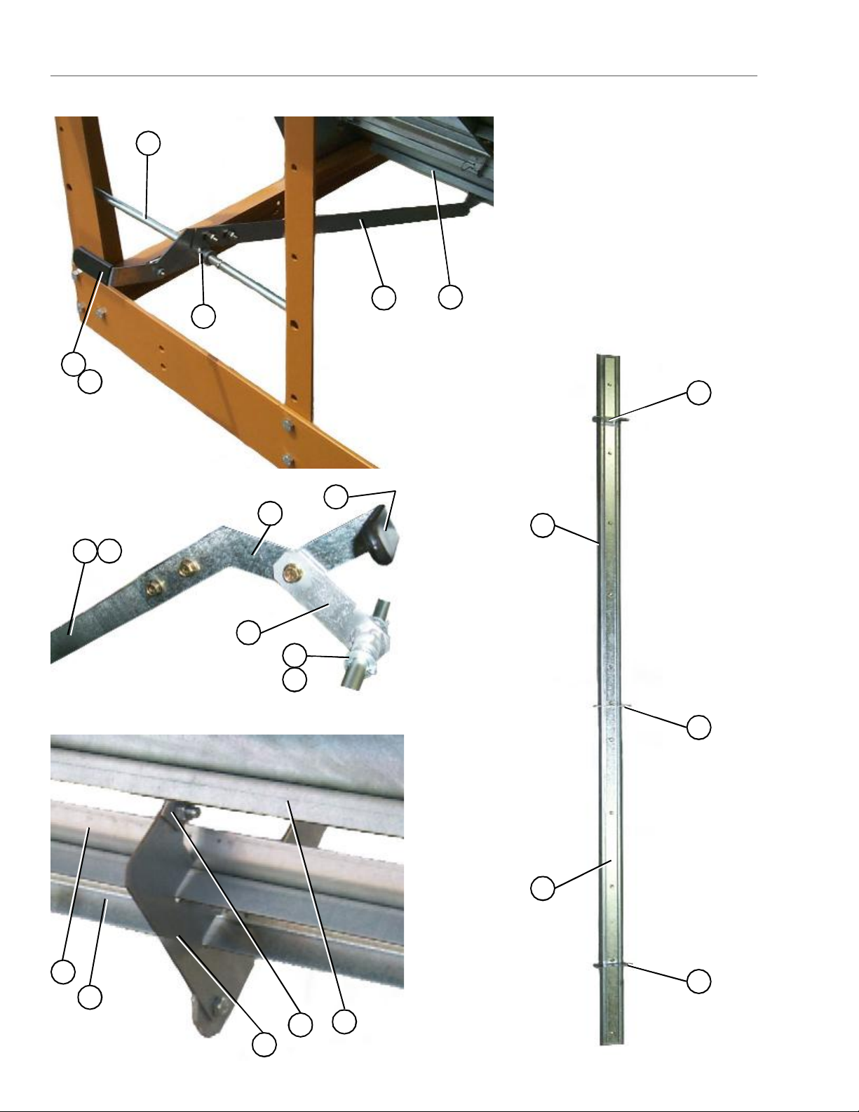
Page 22

Bottom Auger
Bottom Auger (view from center of dryer to
the forward end).
Bottom Auger (view from center of dryer to
the rear end).
1
2
2
3
2
4
Bottom Auger center bearing and support.Bottom Auger rear bearing.
22
8 75 7 6
PNEG-1447
Page 23

Bottom Auger
1
D01-1214
PLENUM CLOSURE DOOR, REAR
111112D01-1134
PLENUM CLOSURE DOOR
68910123D21-0017
AUGER BOTTOM FRONT WELDMENT
113
D31-0092
AUGER BOTTOM FRONT WELDMENT
113
D31-0092
AUGER BOTTOM FRONT WELDMENT (116 3/8" LONG)
14D31-0267
AUGER BOTTOM REAR WELDMENT
11224
D61-0184
AUGER BOTTOM REAR WELDMENT (117 7/8" LONG)
15D01-1290
HANGER BEARING BOTTOM J-PLATE
222446D01-1291
HANGER BEARING BOTTOM C-CHANNEL
111227D01-1246
HANGER BEARING ASSEMBLY (SHORT)
222338D31-0076
SHAFT, AUGER SPLICE
22233
9-19
D01-0481-MS
DISCHARGE BOX ASSEMBLY
111119D01-1884
DISCHARGE WELDMENT
10
D01-1886
MOIST. SAMPLER TUBE COVER PLATE
11
D01-0405
GRAIN SAMPLER ASSEMBLY
12
D01-1752
DISCHARGE SIDE COVER
13
D01-1751
DISCHARGE SICE PANEL MC
14
D31-0298
DISCHARGE SIDE PANEL
15
D01-1885
MOIST. SAMPLER COVER PLATE
16
D01-1650
REAR AUGER BEARING SHIELD
17
D31-0299
DISCHARGE BOX BEARING PLATE
18
D01-0466
DISCHARGE TOP PANEL
19
D01-0467
DISCHARGE TOP FLAPPER
20
D32-0001
FLANGETTE BEARING
1111121D31-0005
SHAFT, TOP & BOT AUGER STUB
11111
NOT SHOWN
D31-0079
DISCHARGE AUGER WELDMENT
11111
1/ASSEMBLY
1/ASSEMBLY
Rear Discharge Box.Auger bearing.
18 19
9
10
11
ITEM
NUMBERPART NUMBER
12
13 14 15
DESCRIPTION1214S1218S1220S1222S1226S
17
20
16
21
PNEG-1447
1/ASSEMBLY
1/ASSEMBLY
1/ASSEMBLY
1/ASSEMBLY
1/ASSEMBLY
1/ASSEMBLY
1/ASSEMBLY
1/ASSEMBLY
1/ASSEMBLY
23
Page 24

Top Auger With Wet Bin Assembly
Top Auger with wet bin (switch paddle end).
6
5
2
1
1
43
7
9
13 14
14a
8
1
3
10
11
12
8
5
9
24
Top Auger (fill end).
PNEG-1447
Page 25

Top Auger With Wet Bin Assembly
ITEM
Top Auger bearing support.Top Auger bearing support (inside view).
16
17
15
10 21 22 18
19
20
22
21
7
23
24
7
25
16
NUMBERPART NUMBER
1D01-1521WET BIN SIDE,4'SIDE GALV. PERF4424
1D01-1522WET BIN SIDE,6'SIDE GALV. PER 26466
2D01-0103MERCURY SWITCH SHAFT11111
3D21-0003TOP EDGE ANGLE 71.875"22
3D31-0004TOP EDGE ANGLE 95.875"2244
3D01-0168TOP EDGE ANGLE 119.875"242
3aD31-0003TOP EDGE ANGLE SPLICE 22244
5D01-0147TOP AUGER HOUSING HINGE L.H.22222
6D01-0167MERCURY SWITCH PADDLE WELDMENT11111
7D21-0015AUGER TOP FRONT WELDMENT11
7D31-0091AUGER TOP FRONT WELDMENT111
7D31-0267AUGER TOP & BOTTOM WELDMENT1122
7D61-0184AUGER WELDMENT 117 7/8"1
8D01-0148TOP AUGER HOUSING HINGE R.H.22222
9D01-1525WET BIN END22222
10D21-0002TOP AUGER TROUGH SIDE/6'22
10D31-0010TOP AUGER TROUGH SIDE/8'2244
10D01-0161TOP AUGER TROUGH SIDE/10'242
11D01-1650REAR AUGER BEARING COVER11111
12D31-0028TOP AUGER HOUSING END22222
13D32-0001BEARING 1 1/2" DIA W/FLANGETTE22222
14D31-0090SHAFT, TOP AUGER FRONT11111
14aD31-0005SHAFT, TOP AUGER STUB REAR11111
15D01-1123TOP AUGER COVER, 30.25"11111
15D01-1124TOP AUGER COVER, 24.25"35757
15D01-1125TOP AUGER COVER, 20.25"22244
16D31-0015TOP AUGER BEARING SUPPORT11122
17D31-0011CENTER STABILIZER BEAM11122
18D31-0009GUSSET ATTACH BRACKET22244
19D31-0001CENTER HANDRAIL GUSSET L.H.22244
20D31-0002CENTER HANDRAIL GUSSET R.H.22244
21D21-0001-YHAND RAIL-SUPPORT,1"EMTX71.75"22
21D31-0006-YHAND RAIL SUPPORT,1"EMTX95.75"2244
21D01-0151-YHAND RAIL, 1"EMT X119.75"LONG242
22D01-0140HANGER BRACKET-HANDRAIL GALV.1616162424
23D31-0008TOP AUGER TROUGH SPLICE22244
24D01-1245TOP AUGER BEARING HANGER ASSY.11122
25D31-0076SHAFT, AUGER SPLICE11122
DESCRIPTION1214S1218S1220S1222S1226S
PNEG-1447
25
Page 26

Bottom Auger drive components
Bottom Auger Drive
12
1
2
3
4
5
11
Bottom Auger motor and motor mount.
9
10
8
7
6
11
13
Rear drive tension adjustment.
13
18
16
17
Forward drive tension adjustment.
5
13
14
16
15
6
4
26
PNEG-1447
Page 27

Bottom Auger Drive
Bottom auger and metering roll drive guard.
21
19
20
22
ITEM
NUMBER PART NUMBER
1 D01-1376BOTTOM FRONT ANGLE BRACKET 11111
2 MHC00490BELT-V BX82 22222
3 2818-2 SHEAVE 2GR 3.35Dx1 1/8" 1 1
3 D62-0003 SHEAVE 2GR 4.25Dx1 3/8" 1 1 1
4 D01-0012HITCH BRACKET, RIGHT 11111
5 D01-1373BELTGUARD, UNLOAD MOTOR SHROUD 11111
6 D01-0029HITCH WELDMENT 11111
7 D01-0011HITCH BRACKET, LEFT 11111
8 D01-2435Front Bearing Plate 2008 11111
9 D03-0304SHEAVE 2GR 20" GRIPBELT 11111
10 D32-0019BUSHING Q1-1 1/2" SPLIT TAPER 11111
11 D01-0065SPACER, BEARING SHIELD 22222
*12 D03-1109 MOTOR 5HP 1PH 1800RPM 1 1
12 500-3 MOTOR 5HP 3PH 1800RPM 1 1
*12 D03-1010 MOTOR 7.5HP 1PH 1800RPM 1
12 712-3 MOTOR 7.5HP 3PH 1800RPM 1 1
12 1000-3 MOTOR 10HP 3PH 1800RPM 1
13 D01-0081MOTOR MOUNT - BOTTOM AUGER 11111
14 D01-0008FRONT & REAR FRAME TIE CHANNEL 44466
15 D01-0007CORNER LEG 66688
16 D01-0017MOTOR ADJUSTMENT BRACKET 22222
17 D21-0011 FRAME RAIL, 14' R.H. 1
17 D31-0044 FRAME RAIL, 18' R.H. 1
17 D61-0002 FRAME RAIL, 20' R.H. 1
17 D101-00 02 FRAM E RAIL , 2 2' R.H. 1
17 D71-0002 FRAME RAIL, 26' R.H. 1
18 D01-0016MOTOR MOUNT SUPPORT BRACKET 11111
19 D01-1372BELTGUARD, UNLOAD FRONT SHIELD 11111
20 PR-331PEAK CAP HANDLE 22222
21 DC-971DECAL, BELT DRIVE WARNING 22222
22 DC-972DECAL, CHAIN WARNING 22222
*ITEM 12, PART Nos D03-1109 & D03-1010 ARE SINGLE PHASE MOTORS
DESCRIPTION 1214S 1218S 1220S 1222S 1226S
PNEG-1447
27
Page 28

T op Auger Drive
1
6
1
2
3
4
Belt guard upper mount.
5
Top Auger drive components.
Top Auger belt guard cover.
28
12
13
PNEG-1447
Page 29

T op Auger Drive
7
8
9
10
11
Top Auger motor and motor mount.
ITEM
NUMBER PART NUMBER
1 D01-0453 TOP AUGER BELTGARD BODY 1 1 1 1 1
2 D52-0001 SHEAVE 2GR 16" GRIPBELT 1 1 1 1 1
3 D32-0019 BUSHING Q1-1 1/2" SPLIT TAPER 1 1 1 1 1
4 D01-0464 BELT-V BX97 2 2 2 2 2
5 2818-2 SHEAVE 2GR 3.35Dx1 1/8" BORE 1 1
5 D62-0003 SHEAVE 2GR 4.25Dx1 3/8" 1 1 1
6 D01-0155 MOUNTING BRACKET-BELT GD SPCR 1 1 1 1 1
7 D01-0424 DRYER TOP HAND HOLD 1 1 1 1 1
* 8 D03-1109 MOTOR 5HP 1PH 1800RPM 1 1
8 500-3 MOTOR 5HP 3PH 1800RPM 1 1
* 8 D03-1010 MOTOR 7.5HP 1PH 1800RPM 1
8 712-3 MOTOR 7.5HP 3PH 1800RPM 1 1
8 1000-3 MOTOR 10HP 3PH 1800RPM 1
9 D01-0173 TOP MOTOR MOUNT WELDMENT 1 1 1 1 1
10 D01-0465 TURNBUCKLE 1/2" X 6" PLATED 1 1 1 1 1
11 D01-0170 A NCHO R BRACKET-MOT OR MOUNT 1 1 1 1 1
12 D01-0452 -Y TOP AUGER BELTGUA RD CO VER OCHR 1 1 1 1 1
13 DC-971 DECAL , B EL T DRIVE WARNING 2 2 2 2 2
*ITEM 8, PART Nos D03-1109 & D03-1010 ARE SINGLE PHASE MOTORS
DESCRIPTION 1214S 1218S 1220S 1222S 1226S
PNEG-1447
29
Page 30

Metering Roll Drive
SCR Motor/Reduction drive and motor mount assembly.
1
7
2
3456
8
30
14
14
10
Meter roll drive train components.
12
9
17
15
9
11
8
12 13
14
16
PNEG-1447
Page 31

Metering Roll Drive
ITEM
Front meter roll bearing.Rear meter roll bearing.
18
19
20
NUMBERPART NUMBER
1D01-0007CORNER LEG PORTABLE DRYER66688
2D21-0010FRAME RAIL, 14' LEFT1
2D31-0043FRAME RAIL, 18' LEFT1
2D61-0001FRAME RAIL, 20' LEFT1
2D101-0001FRAME RAIL, 22' LEFT1
2D71-0002FRAME RAIL, 26' LEFT1
3D01-0016MOTOR MOUNT SUPPORT BRACKET11111
4D01-0081MOTOR MOUNT 11111
5D01-0704SCR MOTOR GEARBOX MOUNT11111
6D01-0008FRONT & REAR FRAME TIE CHANNEL44466
7D03-0232MOTOR 3/4 HP DC W/GEAR BOX 50:111111
8D01-2435Front Bearing Plate 200811111
9D02-0029SPROCKET 40H3022222
10D31-0316FRONT BOTTOM AUGER SHAFT11111
11D32-0001FLANGETTE BEARING 1 1/2"22222
12D01-0196SPROCKET IDLER ASSEMBLY22222
13D03-0257SPROCKET 4015 x 7/8" BORE W/KEYWAY11111
14S-9168KEY SQ. 1/4" x 1"33333
15S-6290CHAIN #40 ROLLER CHAIN6ft6ft6ft6ft6ft
16D02-0031#40 CHAIN CONNECTING LINK11111
17DC-972DECAL, CHAIN WARNING22222
18D01-0003ADAPTOR PLATE44444
19GK1583FLANGETTE BEARING 1", W/LOCK COLLAR44444
20D01-0006METER ROLL DRIVE SHAFT (front)22222
21D01-0272METER ROLL SHAFT STUB (rear)22222
DESCRIPTION1214S1218S1220S1222S1226S
18
19
21
PNEG-1447
31
Page 32

Fan Heater Housing Assembly
Fan Heater housing assembly. 28” burner support and collector
cup.
1
2
3
14a
13a
13
14
36”& 40” burner support and collector cup.
4
5
6
7
8
32
PNEG-1447
Page 33

Fan Heater Housing Assembly
Fan Heater
Dryer Model No.
ITEM
NUMBERPART NUMBER
1D01-1996WRAPPER, 28" FAN HEATER1
1D01-1963WRAPPER, 36" FAN HEATER11
1D01-1997WRAPPER, 40" FAN HEATER1
2D01-0529STRAIGHTENING VANE, 28" F/H11
2D01-1452STRAIGHTENING VANE, 36-42" F/H111111
3D01-0528INNER CAN, 26" & 28" F/H1
3D01-1480INNER CAN, 36" F/H11
3D01-1479INNER CAN, 40" F/H1
4401-5759-6-BACCESS DOOR-GALV FAN BLACK1111
5069-1303-2SIGHT GLASS1111
6DC-1224DECAL, DANGER HI-VOLTAGE1111
7DC-1225DECAL, WARNING ROTATING BLADE1111
8DC-1227DECAL, WARNING FIRE1111
9HF-983COLLECTOR CUP, 28" FAN HEATER1
9aD01-1484COLLECTOR CUP, 36" FAN HEATER11
9aD01-1485COLLECTOR CUP, 40" FAN HEATER1
10HF-7092SUPPORT PLATE, 28" FAN HEATER1
10aD01-1482SUPPORT BRACKET, 36" FAN HEATER11
10aD01-1483SUPPORT BRACKET, 40" FAN HEATER1
DESCRIPTION2812361236154025
PNEG-1447
Matching the right size fan heater to the model number of the dryer.
1214S1218S1220S1222S1226S
28", 10 - 12 hp(2812)x
36", 10 - 12 hp(3612)x
36", 10 - 16 hp(3615)xx
40", 25 hp(4025)x
33
Page 34

Fan Motor, Motor Mount, & Fan Blade
DESCRIPTION
Fan motor and motor mount.Fan blade and bushing.
1 2 3 4
FAN HEATER;
(Dia., HP)
28" 12Hp
36" 12Hp
36" 15Hp
40" 25Hp
PART NUMBER
ITEM NUBER
1MOTOR MOUNTD01-0530D01-0530D01-0530D01-0530D01-0530
2MOTORCD-0110CD-0239CD-0239CD-0239D03-0193
3FAN BLADED03-0302D03-0302D03-0302D03-0302D03-0302
4BUSHINGPT0778PT0778PT0778PT0778PT0778
1MOTOR MOUNTD01-1478D01-1478D01-1478D01-1478D01-1478
NOT SHOWNMOTOR MOUNT ADAPTERCD-0233CD-0233CD-0233CD-0233CD-0233
2MOTORCD-0110CD-0239CD-0239CD-0239CH-6819
3FAN BLADED01-0468D01-0468D01-0468D01-0468D01-0468
4BUSHINGFH-1009FH-1009FH-1009FH-1009FH-1009
1MOTOR MOUNTD01-1478D01-1478D01-1478D01-1478D01-1478
2MOTOR002-1073-2CH-1050CH-1050CH-1050CH-6820
3FAN BLADED82-0002D82-0002D82-0002D82-0002D82-0002
4BUSHINGFH-1009FH-6963FH-6963FH-6963FH-6963
1MOTOR MOUNTN/AD01-1477D01-1477D01-1477D01-1477
2MOTORN/AC-2049C-2049C-2049CH-6692
3FAN BLADEN/AD72-0003-25D72-0003-25D72-0003-25D72-0003-25
4BUSHINGN/ACE-00617CE-00617CE-00617CE-00617
220V 1Ph208V 3Ph220V 3Ph440V 3Ph575V Ph
34
PNEG-1447
Page 35

Air Mixer Assemblies
ITEM
Air mixer assemblies (36” air mixer shown in photo).
1
1a
2
NUMBERPART NUMBER
1-2D01-0955AIR MIXER ASSEMBLY, 28"1
1D01-0951AIRMIXER CAN, 28" x 15" LONG
1aD01-0950AIRMIXER CAN, 28" x 8" SHORT
2CD-0228SMALL DIA. CAN AIR MIXER VANE
1-2CD-0113AIR MIXER ASSEMBLY, 36"1
1&1aD01-1303AIRMIXER CAN, 36" W/ACCESS
2CD-0083AIR MIXER VANE
1-2CD-0117AIR MIXER ASSEMBLY, 40"1
1&1aD01-1218AIRMIXER CAN, 40" W/ACCESS
2CD-0083AIR MIXER VANE
DESCRIPTION
28" F/H36" F/H40" F/H
1/ASSEMBLY
1/ASSEMBLY
6/ASSEMBLY
2/ASSEMBLY
8/ASSEMBLY
2/ASSEMBLY
8/ASSEMBLY
PNEG-1447
35
Page 36

Flame Probe, Ignitor, Vaporizer Coil, and Burner Assemblies
10
CD-0414
VAPORIZOR COIL 26 28" 3 WRAP
110HF-7207
VAPORIZER COIL 36-42"10-17HP
1110
HF-7251
VAPORIZER 3/4" 3 WRAP 36-42"
110HF-7319
VAPOR COIL (SPIRAL) 42" 40HP
1
2
8
Ignitor
3
Flame probe
ITEMPART No.DESCRIPTION2812361236154025
Burner housing high limit switch.
9
10
Items 9 and 10 are used in LP Fan/Heaters only.
7
6
5
4
11 12 13 14 15
36
28” Fan heater burner assembly.
16
19
18
17
PNEG-1447
Page 37

1-3
TF-1559-N
FLAME PROBE ASSY NETWK
1111HH-7025
BOOT 8MM SILICONE 90DEGREE
2
THH-4179
FLAME SENSOR 6" LONG ROD
3
CD-0187
FLAME SENSOR BRACKET
4-8
TF-1558
IGNITOR ASSEMBLY
1114HF-7204
DUAL PROBE IGNITOR BRACKET
5
D01-0878
IGNITOR AIR DEFLECTOR ANGLE
6
HF-7201
IGNITOR HALF CLAMP
7
CD-0238
IGNITOR FLAME
8
TF-1876
IGNITION WIRE ASSY (includes both wires)
9
HH-7054
CONE 26/28" BURNER S.S.
19HH-7056
CONE 36/42" BURNER S.S.
111011THH-4064
UNILET TYPE LRL CONDUITBX1/2"
11112027-1006-9
THERMOSTAT - HI LIMIT 200F AUT
11113D01-1473
HOUSING HI LIMIT PLATE
11114No Number
LID FOR LRL CONDUIT BOX IS PART OF ITEM 11
15
TFC-0076
NEOPRENE GASKET, CONDUIT BODY
111
15-18
BA-28
28" BURNER ASSEMBLY
115HF-7629
DIVERTER WELDMENT 28"
16
THF-3144
FLAME SPREADER 28"
17
THF-3141
HEATER GUN MACHINED 28"
18
THF-3113
28" DIVERTER BRACKET
19-23
BA-36
36" BURNER ASSEMBLY
119THF-3038
DIVERTER BRACKET 36" & 40"
20
THF-3038P
DIVERTER BRACKET 36" & 40" PERFED
21
THF-3039
DIVERTER BRACKET 36" & 40" W/HOLE
22
THF-3057
FLAME SPREADER 36-42"
23
CD-0091
BURNER WELDMENT CD 36" & 40"
24-27
BA-40-2
40" BURNER ASSEMBLY
124CD-0448P
DIVERTER BRACKET 42" PERFD
25
CD-0448
DIVERTER BRACKET 42"
26
CD-0208
BURNER WELDMENT CD 42"
27
THF-3057
FLAME SPREADER 36-42"
1/ASSEMBLY
1/ASSEMBLY
1/ASSEMBLY
1/ASSEMBLY
1/ASSEMBLY
Flame Probe, Ignitor, Vaporizer Coil, and Burner Assemblies
36” Fan heater burner assembly.40” &42” Fan heater burner assembly.
19
20
ITEMPART NUMBER
24
2321
DESCRIPTION
SEE CHART ON PAGE 36
27
2522
28" F/H36" F/H40" F/H
1/ASSEMBLY
1/ASSEMBLY
1/ASSEMBLY
1/ASSEMBLY
2/ASSEMBLY
2/ASSEMBLY
NOT APPLICABLE
26
PNEG-1447
1/ASSEMBLY
1/ASSEMBLY
1/ASSEMBLY
3/ASSEMBLY
4/ASSEMBLY
1/ASSEMBLY
1/ASSEMBLY
4/ASSEMBLY
4/ASSEMBLY
1/ASSEMBLY
37
Page 38

LP Pipe Train Assemblies
26” & 28” Fan heater LP pipe train assembly.
24 25 26
1
11
2 3 4 5 6 7 8 9
10
4
23 24
21
22
18
191720
26” & 28” Vaporizer coil connection and adjustment
brackets.
1213
14
121617
15
2
11
38
29
27
28
PNEG-1447
Page 39

LP Pipe Train Assemblies
ITEM
NUMBERPART NUMBER
1THH-4120ELBOW, 3/4" - 90 DEG SCH 401
2THH-4121NIPPLE, 3/4" CLOSE SCH 402
3007-1048-3BALL VALVE, 3/4" W/LEVER HANDLE 1
4THH-4125NIPPLE, 3/4" x 2 SCH 402
5THH-4154TEE, 3/4" x 3/4" x 1/4" SCH 401
6HH-2984GUAGE, PRESSURE 0-30# LP1
7THH-4136NIPPLE, 3/4" x 3" SCH 401
8056-2223-8VALVE, SOLENOID 3/4"NPT 115V DIN1
9056-2228-7VALVE, SOLENOID 3/4"NPT 115V BYP1
10THH-4066ELBOW 3/4-90 STREET SCH 401
11THH-4149ELBOW, 3/4"-1/2" REDUCER SCH 401
12HH-2029NIPPLE, 1/2" x 1 1/2" SCH 402
13HH-1453TEE, 1/2" x 1/2" x 1/2" SCH 401
14HH-7013SWITCH SCREW-IN VAPOR HI-LIMIT1
15THH-4071ELBOW 1/2"-90 SCH 401
16TFC-0023-50REGULATOR, 1/2" NPT 50PSI1
17D07-0019NIPPLE, 1/2" x 1 1/2" SCH 802
18031-1008-7PRESSURE RELIEF VALVE 300PSI1
19HH-4846TEE, 1/2" x 1/2" x 1/4" SCH 801
20HH-1251STRAINER, 1/2" "Y" SCH 801
21HH-1932ELBOW, 1/2" PIPE - 1/2" FLARE BRASS1
22TFC-0095HOSE, 1/2" x 24" LP GAS2
23TF-1227PIPETRAIN BRACKET FOR 36 & 42"1
24326-1047-9U-BOLT 5/16-18 X 1-3/8 X 2-3/163
25401-5503-8PLUMBG MTG BRKT1
26401-5255-5PLUMBG MTG BASE BRKT1
27HH-4847ELBOW, 1/2"-90 SCH 802
28D01-2217VAPORIZER SUPPORT PLATE BLACK
29410-1783-1-BVAPORIZER ADJUSTING WELD 1/2"
DESCRIPTION
28" FAN
1
1
PNEG-1447
39
Page 40

36” Fan heater LP pipe train assembly.
1
2 3 4 5 6 7 8 9
LP Pipe Train Assemblies
24 25 26
10
4
23 24
21
22
18
191720
36” Vaporizer coil connection and adjustment brackets.
1213
14
121617
15
2
11
40
29
27
28
PNEG-1447
Page 41

LP Pipe Train Assemblies
ITEM
NUMBER
1THH-4120ELBOW, 3/4" - 90 DEG SCH 401
2THH-4121NIPPLE, 3/4" CLOSE SCH 402
3007-1048-3BALL VALVE, 3/4" W/LEVER HANDLE 1
4THH-4125NIPPLE, 3/4" x 2 SCH 402
5THH-4154TEE, 3/4" x 3/4" x 1/4" SCH 401
6HH-2984GUAGE, PRESSURE 0-30# LP1
7THH-4136NIPPLE, 3/4" x 3" SCH 401
8056-2223-8VALVE, SOLENOID 3/4"NPT 115V DIN1
9056-2228-7VALVE, SOLENOID 3/4"NPT 115V BYP1
10THH-4066ELBOW 3/4-90 STREET SCH 401
11THH-4149ELBOW, 3/4"-1/2" REDUCER SCH 401
12HH-2029NIPPLE, 1/2" x 1 1/2" SCH 402
13HH-1453TEE, 1/2" x 1/2" x 1/2" SCH 401
14HH-7013SWITCH SCREW-IN VAPOR HI-LIMIT1
15THH-4071ELBOW 1/2"-90 SCH 401
16TFC-0023-50REGULATOR, 1/2" NPT 50PSI1
17D07-0019NIPPLE, 1/2" x 1 1/2" SCH 802
18031-1008-7PRESSURE RELIEF VALVE 300PSI1
19HH-4846TEE, 1/2" x 1/2" x 1/4" SCH 801
20HH-1251STRAINER, 1/2" "Y" SCH 801
21HH-1932ELBOW, 1/2" PIPE - 1/2" FLARE BRASS1
22TFC-0095HOSE, 1/2" x 24" LP GAS2
23TF-1227PIPETRAIN BRACKET FOR 36 & 42"1
24326-1047-9U-BOLT 5/16-18 X 1-3/8 X 2-3/163
25401-5503-8PLUMBG MTG BRKT1
26401-5255-5PLUMBG MTG BASE BRKT1
27HH-4847ELBOW, 1/2"-90 SCH 802
28D01-2217VAPORIZER SUPPORT PLATE BLACK1
29410-1783-1-BVAPORIZER ADJUSTING WELD 1/2"1
PART NUMBERDESCRIPTION36" LP F/H
PNEG-1447
41
Page 42

40” LP pipe train assemblies.
1
LP Pipe Train Assemblies
2425
23
2
1
10
232
23
22
1719
40” with 25hp and larger motors vaporizer coil
connection and adjustment brackets.
4
5
6
7
8
1617182021
15
14
9
1312
2
12
11
42
29
28
28
26
27
PNEG-1447
Page 43

LP Pipe Train Assemblies
ITEM
29
HH-1082
ELBOW, 1/2"-90 DEG STREET SCH 80
2
NUMBERPART NUMBER
1THH-4115ELBOW, 1" -90 DEG SCH 402
2007-1104-4NIPPLE, CLOSE 1"4
3007-1296-8BALL VALVE, 1" WITH LEVER HANDLE1
4007-1106-9TEE, 1" x 1" x 3/4"1
5D07-0027REDUCER, 3/4"-1/4" HEX BUSHING1
6HH-2984PRESSURE GUAGE, 0-30# LP1
7THH-4037NIPPLE, 1" x 2 1/2" SCH 401
8056-2224-6VALVE, SOLENOID 1" NPT 115V DIN1
9056-2230-3VALVE, SOLENOID 1" NPT 115V BYPASS1
10007-1242-2NIPPLE, 1" x 2" SCH 401
11007-1288-5ELBOW, 1" - 1/2" SCH 401
12HH-2029NIPPLE, 1/2" x 1 1/2" SCH 402
13HH-1453TEE, 1/2" x 1/2" x 1/2" SCH 401
14HH-7013SWITCH SCREW-IN VAPOR HI-LIMIT1
15THH-4071ELBOW 1/2"-90 SCH 401
16TFC-0023-50REGULATOR, 1/2" NPT - CSA 50PSI1
17D07-0019NIPPLE, 1/2" x 1 1/2" SCH 802
18HH-4846TEE, 1/2" x 1/2" x 1/4" SCH 801
19031-1008-7PRESSURE RELIEF VALVE 300 PSI1
20HH-1251STRAINER, 1/2" "Y" SCH 801
21HH-1932ELBOW, 1/2" PIPE - 1/2" FLARE BRASS1
22TF-1227PIPETRAIN BRACKET FOR 36 & 42"1
23326-1047-9U-BOLT 5/16-18 X 1-3/8 X 2-3/163
24401-5503-8PLUMBG MTG BRKT1
25401-5255-5PLUMBG MTG BASE BRKT1
26D01-2217VAPORIZER SUPPORT PLATE BLACK1
27D01-2220VAPORIZER ADJUSTING WELD 3/4"1
28007-1930-2REDUCER, BELL 3/4" - 1/2" SCH 802
DESCRIPTION
40" LP
PNEG-1447
43
Page 44

NG Pipe Train Assemblies
26” & 28” Fan heater NG pipe train assembly.
12 13 14
1 2 3 4 5 6 7 8
1A
10
4
9
2
11
ITEM
NUMBERPART NUMBER
1THH-4120ELBOW, 3/4" -90 SCH 401
2THH-4121NIPPLE, 3/4" CLOSE SCH 402
3007-1048-3BALL VALVE, 3/4" W/LEVER HANDLE1
4THH-4125NIPPLE, 3/4" x 2" SCH 402
5THH-4154TEE, 3/4" x 3/4" x 1/4" SCH 401
6D08-0022GAUGE, PRESSURE 0-15#1
7THH-4136NIPPLE, 3/4" x 3" SCH 401
8056-2223-8VALVE, SOLENOID 3/4"NPT 115V DIN1
9056-2228-7VALVE, SOLENOID 3/4"NPT 115V BYP1
10THH-4066ELBOW, 3/4" x 90 DEG STREET SCH 401
11007-1307-3ELBOW, 1 - 3/4" REDUCER SCH 401
12326-1047-9U-BOLT 5/16-18 X 1-3/8 X 2-3/162
13401-5503-8PLUMBG MTG BRKT1
14401-5255-5PLUMBG MTG BASE BRKT1
DESCRIPTION
28" FANS
44
PNEG-1447
Page 45

36” Fan heater NG pipe train assembly.
12 13 14
1
NG Pipe Train Assemblies
2
8
7
2 3 2 4
7 9
5
6
10
11
PNEG-1447
ITEM
NUMBER
1007-1307-3ELBOW, 1" - 3/4"1
2007-1104-4NIPPLE, CLOSE 1"3
3007-1296-8BALL VALVE, 1" W/LEVER HANDLE1
4007-1106-9TEE, 1" x 1" x 3/4"1
5D07-0027REDUCER, 3/4" - 1/4" HEX BUSHING1
6D08-0022GAUGE, PRESSURE 0-15#1
7007-1242-2NIPPLE, 1" x 2" SCH 402
8THH-4115ELBOW, 1"-90 DEG. SCH 401
9056-2224-6VALVE, SOLENOID 1"NPT 115V DIN1
10056-2230-3VALVE, SOLENOID 1"NPT 115V W/BYP1
11THH-4164ELBOW, 1"-90 DEG. STREET SCH 401
12326-1047-9U-BOLT 5/16-18 X 1-3/8 X 2-3/162
13401-5503-8PLUMBG MTG BRKT1
14401-5255-5PLUMBG MTG BASE BRKT1
PART NUMBERDESCRIPTION36" FAN
45
Page 46

NG Pipe Train Assemblies
40” & 42” Fan heater NG pipe train assembly.
11 12 13
1
2
1
7
2 3 2 4
7 9
5
6
10
8
ITEM
NUMBERPART NUMBER
1THH-4115ELBOW, 1" - 90 DEG SCH 402
2007-1104-4NIPPLE, CLOSE 1"3
3007-1296-8BALL VALVE, 1" W/LEVER HANDLE1
4007-1106-9TEE, 1" x 1" x 3/4"1
5D07-0027REDUCER, 3/4" - 1/4" HEX BUSHING1
6D08-0022GAUGE, PRESSURE 0-15#1
7007-1242-2NIPPLE, 1" x 2" SCH 402
8THH-4164ELBOW, 1"-90 DEG. STREET SCH 401
9056-2224-6VALVE, SOLENOID 1"NPT 115V DIN1
10056-2230-3VALVE, SOLENOID 1"NPT 115V W/BYP1
11326-1047-9U-BOLT 5/16-18 X 1-3/8 X 2-3/162
12401-5503-8PLUMBG MTG BRKT1
13401-5255-5PLUMBG MTG BASE BRKT1
DESCRIPTION
40" FANS
46
PNEG-1447
Page 47

Fan Heater Orifices
LIQUID PROPANE ORIFICES
NATURAL GAS ORIFICES
FAN HEATERORIFICE SIZEPART NUMBERITEM NO.
28"12hp.25"THF-32413
36"12hp.2813"THF-32423
36"15hp.3281"CD-01503
40"25hp.3438"THF-30583
FAN HEATERORIFICE SIZEPART NUMBERITEM NO.
28"12hp.375"THF-31403
36"12hp.4063"THF-32433
36"15hp.5"THF-32443
40"25hp.5156"THF-32463
3
PNEG-1447
47
Page 48

Liquid propane fuel supply line.
LP Supply Line
1
2
3
4
5 8
4
6
Supply line mounting brackets.
14
15
13
16
4
12
11 10
7
9 1
ITEM No.PART No.
1TFC-0027
2D67-0015RDCR 3/4" x 1/4" BELL SCH 8011
3D67-0016NIPPLE, 3/4" x 8" SCH 8011
4HH-7036TEE, 3/4" x 3/4" x 1/2" SCH 8022
5D67-0019NIPPLE, 3/4" x 42" SCH 801
5D01-1011NIPPLE, 3/4" x 46" SCH 801
6D67-0018NIPPLE, 3/4" x 68"1
6D01-1018NIPPLE, 3/4" x 68"1
7D67-0011ELBOW, 3/4"-90 SCH 8011
8D07-0019NIPPLE, 1/2" x 1 1/2" SCH 8022
9D67-0021NIPPLE, 3/4" CLOSE SCH 8022
10D67-0008STRAINER, "Y" SCH 8011
11D67-0016NIPPLE, 3/4" x 8" SCH 8011
12D28-0001VALVE, 3/4" NPT ELECT SHUTOFF11
13TFC-0092VALVE, 1/2" NPT SOLENOID LP GAS22
14D31-0074GAS MANIFOLD MOUNTING BRACKET33
15HH-1096CLAMP, 1/2"33
16D31-0075GAS MANIFOLD CARRIER BRACKET11
VALVE, 1/4" NPT 250 PSI RELIEF
DESCRIPTION1214S-22S
22
1226S
48
PNEG-1447
Page 49

NG Supply Line
PART NUMBER
5 7 8
1
65
6
7
1
1
2
ITEM No.
1
2D01-1015NIPPLE 2 1/2" x 34" SCH 4011
3D68-0016NIPPLE 2 1/2" x 26" SCH 4011
4D68-0004UNION 2 1/2" FEMALE SCH 4011
5D08-0023VALVE 1" NPT B-COCK2
5D08-0008VALVE 1 1/2" NPT B-COCK2
6THH-4117NIPPLE 1" CLOSE SCH 402
6D08-0009NIPPLE 1 1/2" CLOSE SCH 402
7HH-7087TEE 2 1/2" x 2 1/2" x 1" SCH 402
7D68-0002TEE 2 1/2" x 2 1/2" x 1 1/2" SCH 402
8D68-0010PLUG 2 1/2 SQUARE SCH 4011
9D68-0015VALVE 2 1/2" NPT ELECT SHUTOFF11
10D68-0014ELBOW 2 1/2"-90 SCH 4011
2
11D68-0012NIPPLE 2 1/2" x 4" SCH 4011
12D68-0018NIPPLE 2 1/2" x 9" SCH 4011
13D68-0011STRNR 2 1/2" Y SCH 4011
D01-1013
NIPPLE 2 1/2" x 45" SCH 4011
DESCRIPTION1214S1218S-26S
4
3
PNEG-1447
9
10 11 12 13
49
Page 50

Right & Left Grain and Plenum High Limits
Right grain high limit thermostat enclosures.
Left grain and plenum high limit
thermostat enclosures.
Upper plenum high limit
8
12
7
Upper plenum high limit thermostat.
1
2
Conduit from
right grain high
limit is run to
right lower
junction box.
3
11
4
Lower plenum high limit
Left grain high limit
Grain temperature thermister. There are
2 thermisters in each (right & left)
grain high limit thermostat assemblies.
9
4
Lower plenum high limit thermostat.
10
4
50
Right & left grain high limit thermostat.
5
1
2
8
7
3
1
6
3
7
8
PNEG-1447
Page 51

Right & Left Grain and Plenum High Limits
plenum-thermostat 10' 300deg
(for 14' dryers only)
PLENUM-THERMOSTAT 24' 300DEG
(for dryers that are 16' and longer)
grain thermo hi-lmt 10' 210deg
(for 14' dryers only)
GRAIN THERMO HI-LMT 24' 210DEG
(for dryers that are 16' and longer)
connector 1/2" emt compression
(2/conduit; 1 at each end of the dryer.)
coupler 1/2" emt compression
(couples the lengths of 1/2" emt)
Upper plenum high limit thermostat conduit.
13
14 15 16 12
Lower plenum high limit thermostat conduit.
ITEM No.DESCRIPTIONPART No.
1HIGH LIMIT MOUNTING BRACKETD01-0254
2
2
3ENCLOSURE 4x4x2.5 WHITE PVCFH-6972
4SEALTITE PVC 3/8"FH-7038
5ELBOW 3/8" 90 DEGREE PVC W/NUTFH-7050
6
6
7CONNECTOR 1/2" EMT COMPRESSIOND03-0054
8CONDUIT 1/2" EMT METALLICD03-0057
9GRAIN TEMP THERMISTOR SER2000D03-0258
10SEAL 3/8 STRAIGHT PVC W/NUTFH-7049
11CONNECTOR 3/8" LIQUID-TITE TO 1/2" EMTD03-0060
12CLAMP 1/2" CONDUITHH-1096
13CONDUIT BODY, LL TYPED03-0375
13COVER ALUMINUM, CONDUIT BODYTFC-0075
14PLENUM THERMISTOR BOLTHF-7236
15PIPE SCH 40 1/2"DM60001
16CLAMP, BEAM 1/2"GT3-0241
the following components make up the grain high limit conduits that run through the grain columns. The conduit assemblies are not shown in the
photos.
not shownconduit 1/2" emt metallicD03-0057
not shown
not shown
D03-0004
D03-0377
D03-0005
D03-0378
D03-0054
D33-0002
not shown
PNEG-1447
enclosure 4x4x2.5 white pvc (as of 2003 a 4x4 enclosure has been added to these assemlies and is mounted
on the rear column end panels into which thr grain high limit thermostat conduits now terminate.)
FH-6972
51
Page 52

Lower Junction Box, Meter Roll Motor Conduit, Rear Discharge Conduit
Lower junction box (left).Lower junction box (right).
5
3
7
1 2 3 4
Meter roll motor conduit connection.
6
7
Conduit to
Meter Roll
Motor
(see photo
below)
4
6
5
2
1 8 10
Conduit to Meter Roll Speed
Sensor & Rear Discharge Switch
(see photos below & on next page)
1
8
9
2
1
Meter roll speed sensor and rear discharge switch conduit.
This is a photo of the front section of the conduit that runs
through the gussets on the left side of the dryer.
14
13
12
1
11
Rear discharge switch conduit at rear
left gusset where 1/2” EMT conduit
terminates.
14 13
Coupler for 1/2” EMT conduit.
52
14 15 14
PNEG-1447
Page 53

Lower Junction Box, Meter Roll Motor Conduit, Rear Discharge Conduit
Rear discharge switch conduit at rear left
gusset.
Meter roll speed sensor.
16
17
18
19
2
1
11
1
7
Rear discharge switch (open to show mercury switch).
11 17
20
8
24
9
23
21
ITEM No.DESCRIPTIONPART No.
1SEALTITE PVC 3/8"FH-7038
2CONNECTOR PVC 3/8" 45' W/NUTF-6913
3SEALTITE PVC 3/4"FH-7063
4STRAIGHT PVC W/LOCKNUT 3/4"FH-7053
5FITTING COMPRESSION 3/4-TO BOXD03-0199
6CONDUIT 3/4" EMTD03-0086
7ENCLOSURE 4x4x2.5 WHITE PVCFH-6972
8CONNECTOR 1/2"FH-1310
9WIRE 18/2 TYPE SJOW-A BLACKWR-182SJOWA
10RDCR 3/4"X1/2"HEX BUSHINGD07-0028
11ELBOW 3/8" 90 DEGREE PVC W/NUTFH-7050
12CONNECTOR 3/8" LIQUID-TITE TO 1/2" EMTD03-0060
13CONNECTOR 1/2" EMT COMPRESSIOND03-0054
14CONDUIT 1/2" EMT METALLICD03-0057
15CONNECTOR 1/2" EMT COMPRESSIOND33-0002
16SPEED SENSOR BOX BRACKETD01-0462
17SCR METER ROLL SPEED SENSORD01-0527
18DISCONNECT .187 FEMHH-7046
19METERING ROLL TIMING GEAR ASSBD01-0687
20DISCHARGE SWITCH MOUNTING PLATED01-1105
21COVER ALUMINUM, CONDUIT BODYTFC-0075
22CLIP, MERCURY SWITCHSPD-2098
23MERCURY SWITCHD03-0010
24CONDUIT BODY, LL TYPED03-0375
22
PNEG-1447
53
Page 54

Upper junction box.
Upper Juntion Box, Top Auger Motor Conduit, & Operator Light
Top auger motor conduit.
1
11 10 1 2
3
Operator light.
2
9
4 5 6
Fill switch assembly (installed).
7
9
10
1
11
2
8
12
15
Fill switch assembly (opened).
13
14
Items 9 - 14 are components of the mercury
switch box assembly (fill switch assembly) part
no. D01-0192.
ITEM No.DESCRIPTIONPART No.
1CONDUIT 1/2" EMT METALLICD03-0057
2CONNECTOR 1/2" EMT COMPRESSIOND03-0054
3CLAMP 1/2" CONDUITHH-1096
4CONNECTOR 1/2" EMT TO SEALTITED03-0075
5SEALTITE PVC 1/2"FH-7039
6ELBOW 1/2" 90 DEGREE PVC WITHFH-7052
7LAMP 90 DEGREE W/JUNC.BOXD03-0117
8BULB, 100W 130V ROUGH SERVICED03-0575
9ENCLOSURE 4x4x2.5 WHITE PVCFH-6972
10CONNECTOR 1/2"FH-1310
11WIRE 18/2 TYPE SJOW-A BLACKWR-182SJOWA
12MOUNTING PLATE WLDMNT, MERC.BXD01-0358
13MERCURY SWITCH 6-DEG. 6" LEADSD03-0010
14CLIP MERCURY SWITCHSPD-2098
15MERCURY SWITCH SHAFTD01-0103
54
9
PNEG-1447
Page 55

Air switch assembly (part # D01-0672).
Air Switch Assembly
Air switch assembly (internal parts).
3
10
11
7
9
2
8
4 5 6
1
Lower air switch assembly (installed).Upper air switch assembly (installed).
10
1-9
11
12
11
PNEG-1447
10
1-9
ITEM No.PART No.
1-9D01-0672AIR SWITCH ASSEMBLY2/DRYER
1D01-0671
2D01-0670AIR SWITCH BOX FACE PLATE1/ASSEMBLY
3DC-1103
4D03-0177
5HF-7227COUPLING, 1/4" STD BLACK STEEL1/ASSEMBLY
6HF-7228
7HF-7226NIPPLE, 1/8" CLOSE2/ASSEMBLY
8HF-7229
9D03-0167
ITEM No.DESCRIPTIONPART No.
AIR SWITCH BOX CONDUIT HALF
DECAL, AIR PRESSURE ADJUSTMENT
GROMMET, 11/16" ID x 1" OD
BUSHING, 1/4" - 1/8" HEX
ELBOW, 1/8" - 90 SCH 40
AIR PRESSURE SWITCH
10CONDUIT, 3/8" SEALTITEFH-7038
11CONNECTOR, 3/8" x 90FH-7050
12CONNECTOR, 3/8" STRAIGHTFH-7049
DESCRIPTION
QUANTITY
2/ASSEMBLY
1/ASSEMBLY
1/ASSEMBLY
1/ASSEMBLY
1/ASSEMBLY
1/ASSEMBLY
10
55
Page 56

Network Control Box
elbow 3/4" 90deg pvc
(lower network control box only)
elbow 3/8" 90deg pvc
(upper network control box only)
1
2
Conduit from fan
control box (same for
upper and lower
network box)
17
Conduit from air
switch assembly
(same for upper
and lower network
box)
2
18
Conduit from fan
heater pipe train
(same for upper
network box)
18
18
and lower
6 7 8
Conduit from:
1.)lower junction box (lower
19a
19b
1.)upper network box
(lower network box)
2.)upper plenum high limit
(upper network box)
network box)
2.)lower network box (upper
network box)
Conduit from:
3
4
5
9
16
15
14
13
12
11 10 5
ITEM No.DESCRIPTIONPART No.
1NETWOK BOX MOUNTING CHANNELD01-1664
2ENCLOSURE, 12" x 10 " x 5.25" TF-1439
3PLASTIC HOLE PLUG 1/2" DIAHH-2833
4DECAL, NETWORK FAN/HEATERDC-1513
5CONTROL BOARD MOUNTING PLATETF-1426
6CONTROL BOARD RESTTF-1429A
7DECAL, GROUNDDC-1254
8GROUND LUGFH-6634
9FAN/HEATER NETWORK CONTROL BOARDHF-7276
10HINGE, ALUMINUMD02-0037
11CONTROL BOARD RESTTF-1429
12NETWORK BOX BACK PANELTF-1428
13TERMINAL-BLOCK ENTRELEC 4MMD01-0531
14TERMINAL-BLANK END PROTECTORD01-0532
15TERMINAL-ENTRELEC END STOPD01-0533
16TERMINAL-ENTRELEC GROUND BLOCKD01-0534
17elbow 1/2" 90deg pvcFH-7052
18elbow 3/8" 90deg pvcFH-7050
19a
19b
FH-7054
FH-7050
56
PNEG-1447
Page 57

Fan Heater Electrical Box
Fan Heater control box and electrical components.
1
2 3
4
5 13
12
14
6 11 7 8 9
ITEM
NUMBERPART NUMBER
1F-942ELECT. CONTROL BOX LID111
2CD-0005FAN CONTROL BOX WRAPPER 26-28"1
2CD-0065FAN CONTROL BOX WRAPPER 36"1
2CD-0193FAN CONTROL BOX WRAPPER 40-42"1
3FH-4429-1LATCH CONTROL BOX222
4CD-0202FAN CONTROL BOX BOTTOM 26-28"1
4CD-0203FAN CONTROL BOX BOTTOM 36-42"11
5HH-7048GROMMET 1/2" OD, 3/8" ID333
6HH-7016GROMMET 1 1/2" ID 111
ITEM
NUMBER
7TERMINAL-BLOCK ENTRELEC 4MMD01-0531D01-0531D01-0531D01-0531D01-0531
8TERMINAL-BLANK END PROTECTORD01-0532D01-0532D01-0532D01-0532D01-0532
9TERMINAL-ENTRELEC END STOPD01-0533D01-0533D01-0533D01-0533D01-0533
10TERMINAL-ENTRELEC GRND BLOCKD01-0534D01-0534D01-0534D01-0534D01-0534
11CONTACTORD03-0495D03-0494D03-0494D03-0492D03-0490
12OVERLOADD03-0483D03-0482D03-0482D03-0476D03-0475
13LUG GROUND,#TA-2E160-1137E160-1137E160-1137E160-1137E160-1137
14GRP-TRANSFORMER 2POLE IGNITIONHH-1093-GRPHH-1093-GRPHH-1093-GRPHH-1093-GRPHH-1093-GRP
7TERMINAL-BLOCK ENTRELEC 4MMD01-0531D01-0531D01-0531D01-0531D01-0531
8TERMINAL-BLANK END PROTECTORD01-0532D01-0532D01-0532D01-0532D01-0532
9TERMINAL-ENTRELEC END STOPD01-0533D01-0533D01-0533D01-0533D01-0533
10TERMINAL-ENTRELEC GRND BLOCKD01-0534D01-0534D01-0534D01-0534D01-0534
11CONTACTORD03-0497D03-0494D03-0494D03-0492D03-0491
12OVERLOADD03-0485D03-0483D03-0483D03-0477D03-0478
13LUG GROUND,#TA-2E160-1137E160-1137E160-1137E160-1137E160-1137
14GRP-TRANSFORMER 2POLE IGNITIONHH-1093-GRPHH-1093-GRPHH-1093-GRPHH-1093-GRPHH-1093-GRP
7TERMINAL-BLOCK ENTRELEC 4MMN/AD01-0531D01-0531D01-0531D01-0531
8TERMINAL-BLANK END PROTECTORN/AD01-0532D01-0532D01-0532D01-0532
9TERMINAL-ENTRELEC END STOPN/AD01-0533D01-0533D01-0533D01-0533
10TERMINAL-ENTRELEC GRND BLOCKN/AD01-0534D01-0534D01-0534D01-0534
11CONTACTORN/AD03-0496D03-0496D03-0494D03-0492
12OVERLOADN/AD03-0485D03-0485D03-0482D03-0479
13LUG GROUND,#TA-2N/AE160-1137E160-1137E160-1137E160-1137
14GRP-TRANSFORMER 2POLE IGNITIONN/AHH-1093-GRPHH-1093-GRPHH-1093-GRPHH-1093-GRP
DESCRIPTION
DESCRIPTION
10-12 HP FAN MOTORS (2812, 3612 FAN HEATERS)
220V 1Ph208V 3Ph220V 3Ph440V 3Ph575V 3Ph
220V 1Ph208V 3Ph220V 3Ph440V 3Ph575V 3Ph
220V 1Ph208V 3Ph220V 3Ph440V 3Ph575V 3Ph
10-16 HP FAN MOTORS (3615 FAN HEATERS)
25 HP FAN MOTORS (4025 FAN HEATERS)
28" FAN
HEATERS
36" FAN
HEATERS
40" FAN
HEATERS
10
PNEG-1447
57
Page 58

Control Box Control Panel
ITEM
Network control panel (front).
1
10
2
14
13
3
4
12
11
5 6 7 8 9
NUMBER
1DECAL, NETWORK DRYER 2 FANMISC.DC-1521
2SWITCH 2 POS. SELECTOR AMBERCONTROLD01-0444
3SWITCH 2 POS. SELECTOR GREENCONTROLD01-0446
4SWITCH 3 POS. SELECTOR WHITECONTROLD03-0182
5SWITCH 2 POS. SELECTOR CLEARCONTROLD01-0448
63 POS. SELECTOR SWITCH YELLOWCONTROLD01-0579
7SWITCH 3 POS. SELECTOR BLUECONTROLD01-0449
8SWITCH 3 POS. SELECTOR REDCONTROLD01-0447
9KNOB, AUGAT #PK-70B-1/4MISC.E115-1060
10LATCH, SOUTHCO SLOTTEDMISC.TF-1519
11SWITCH STOP BLOCK (RED)CONTROLD03-0020
12SWITCH START N.O.(ILLUMINATED)CONTROLD03-0017
13SWITCH 3 POS. SELECTOR AMBERCONTROLD01-0445
14TOUCH PANEL TOP DRY AUTOMISC.TAF-6150
DESCRIPTIONCIRCUITPART NUMBER
10
58
PNEG-1447
Page 59

Control Box Control Panel (Inside)
ITEM
Network control panel (rear).
1
7
2
3
6
1
Detailed view of a two
position switch.
Detailed view of a
single position switch.
4
5
4
NUMBER
1LATCH, SOUTHCO SLOTTEDMISC.TF-1519
2NETWORK DRYER DISPLAY BOARDCONTROLD03-0593
3COMPUTER MOUNTING PLATEMISC.TF-1544
4BLOCK, CONTACT N/OCONTROLD63-0006
5BLOCK, LIGHT 12/24/120V LAMPSCONTROLD01-0455
6SCR POTENTIOMETER 10KCONTROLD03-0595
7NETWORK SWITCH PANELMISC.D01-1666
DESCRIPTIONCIRCUITPART NUMBER
4
5
PNEG-1447
59
Page 60

Lower control box back panel.
ITEM
1
Lower Control Box Back Panel
2
3
Emergency stop switch
(outside).
10
11
Emergency stop switch
(inside).
4
5 6 7 8 5
12
9
NUMBER
1FILTER RFI "B" SERIESCONTROLD03-0181
2WIRE TIE ANCHORMISC.D02-0039
3WIRE TIE, 5" PANDUITMISC.D03-0247
4DIN RAIL, TERMINAL BLOCK MOUNTINGMISC.D03-0013
5TERMINAL - ENTRELEC END STOPMISC.D01-0533
6TERMINAL - ENTRELEC GROUND BLOCKMISC.D01-0534
7TERMINAL - BLOCK ENTRELEC 4MMMISC.D01-0531
8TERMINAL - END PROTECTORMISC.D01-0532
9LOWER CONTROL BOX BACK PANELMISC.D01-0486
10EMERGENCY STOP SWITCHSAFETYTF-1279
11DECAL, EMERGENCY STOPMISC.DC-1317
12BLOCK, CONTACT N/CSAFETYD63-0013
DESCRIPTIONCIRCUITPART NUMBER
10
60
PNEG-1447
Page 61

Upper Control Box
Upper control box power distrbution panel.
36
1
35
10
11
12
13
2
3
4
5
6
34
7
33
8
9
32
31
30
29
14
15
PNEG-1447
16
19 21 22 242017 25 26
2318
28
27
61
Page 62

ITEM
1
POWER BOX BOCK PANEL
N/A
D01-0480
D01-0480
D01-0480
D01-0480
D01-0480
2
OVERLOAD
LOAD
D03-0487
D03-0477
D03-0475
D03-0473
D03-0472
3
OVERLOAD
LOAD AUX.
D03-0482
D03-0480
D03-0479
D03-0475
D03-0475
4
OVERLOAD
UNLOAD
D03-0487
D03-0477
D03-0475
D03-0473
D03-0472
5
OVERLOAD
UNLOAD AUX.
D03-0482
D03-0480
D03-0479
D03-0475
D03-0475
6
CONTACTOR
LOAD
D03-0492
D03-0491
D03-0490
D03-0488
D03-0488
7
CONTACTOR
LOAD AUX.
D03-0494
D03-0493
D03-0492
D03-0490
D03-0489
8
CONTACTOR
UNLOAD
D03-0492
D03-0491
D03-0490
D03-0488
D03-0488
9
CONTACTOR
UNLOAD AUX.
D03-0494
D03-0493
D03-0492
D03-0490
D03-0489
10
TERMINAL-BLOCK ENTRELEC 4MM
CONTROL
D01-0531
D01-0531
D01-0531
D01-0531
D01-0531
11
TERMINAL-BLANK END PROTECTOR
CONTROL
D01-0532
D01-0532
D01-0532
D01-0532
D01-0532
12
TERMINAL-ENTRELEC END STOP
CONTROL
D01-0533
D01-0533
D01-0533
D01-0533
D01-0533
13
TERMINAL-ENTRELEC GRND BLOCK
CONTROL
D01-0534
D01-0534
D01-0534
D01-0534
D01-0534
14
RELAY, 3PDT 120V RH3B-U IDEC
CONTROL
HF-7203
HF-7203
HF-7203
HF-7203
HF-7203
15
RELAY BASE, 3PDT
CONTROL
07097555
070975553
07097555
07097555
07097555
16
TRANSFORMER
CONTROL
FH-3807
FH-3807
FH-3807
FH-3807
FH-3807
17
TERMINAL GROUND BAR
GROUND
006-1184-8
006-1184-8
006-1184-8
006-1184-8
006-1184-8
18
NETWORK DRYER CONTROL BOARD MOUNT PLATE
N/A
TF-1713
TF-1713
TF-1713
TF-1713
TF-1713
19
NETWORK DRYER CONTROL BOARD
CONTROL
D03-0587
D03-0587
D03-0587
D03-0587
D03-0587
20
NETWORK DRYER CONTROL BOARD COVER PLATE
N/A
D01-1710
D01-1710
D01-1710
D01-1710
D01-1710
21
BREAKER 6 AMP 1 POLE 110VAC
CONTROL
D03-0661
D03-0661
D03-0661
D03-0661
D03-0661
22
BREAKER 10 AMP 2 POLE DELAYED
METER ROLL
D03-0660
D03-0660
D03-0660
D03-0660
D03-0660
23
BREAKER 3 AMP 2 POLE DELAYED
CONTROL
D03-0726
D03-0728
D03-0726
D03-0726
D03-0726
24
SCR CONTACTOR 15 AMP 3 POLE
METER ROLL
D03-0106
D03-0108
D03-0106
D03-0106
D03-0106
25
SCR DRIVE BOARD BASE UNIT
METER ROLL
D03-0711
D03-0711
D03-0711
D03-0711
D03-0711
26
SCR ISOLATED TERMINAL BOARD
METER ROLL
D03-0592
D03-0592
D03-0592
D03-0592
D03-0592
27
POWER BOX CATCH ANGLE, BOTTOM
N/A
D01-0550
D01-0550
D01-0550
D01-0550
D01-0550
28
MAIN BREAKER
POWER
D01-0493
D01-0503
D01-0450
D03-0271
D03-0175
29
BREAKER
UNLOAD AUX.
D03-0460
D03-0461
D03-0461
D03-0545
D03-0395
30
BREAKER
UNLOAD
D03-0460
D03-0453
D03-0451
D03-0389
D03-0531
31
DISTRIBUTION BLOCK
POWER
D03-0300
D03-0293
D03-0293
D35-0001
D35-0001
32
BREAKER
LOAD AUX.
D03-0460
D03-0461
D03-0461
D03-0545
D03-0395
33
BREAKER
LOAD
D03-0460
D03-0453
D03-0451
D03-0389
D03-0531
34
BREAKER
FAN 1
D03-0466
D03-0461
D03-0461
D03-0545
D03-0395
35
BREAKER
FAN 2
D03-0466
D03-0461
D03-0461
D03-0545
D03-0395
36
POWER BOX CATCH ANGLE, TOP
N/A
D01-0551
D01-0551
D01-0551
D01-0551
D01-0551
NUMBER
1214 Upper Control Box Component Part Numbers
1214S Upper control box power distrbution panel parts listing.
DESCRIPTIONCIRCUIT
220V 1Ph208V 3Ph220V 3Ph440V 3Ph575V 3Ph
1214S PART NUMBER
62
PNEG-1447
Page 63

ITEM
1
POWER BOX BOCK PANEL
N/A
D01-0480
D01-0480
D01-0480
D01-0480
D01-0480
2
OVERLOAD
LOAD
D03-0478
D03-0477
D03-0475
D03-0473
D03-0472
3
OVERLOAD
LOAD AUX.
D03-0482
D03-0480
D03-0479
D03-0475
D03-0475
4
OVERLOAD
UNLOAD
D03-0478
D03-0477
D03-0475
D03-0473
D03-0472
5
OVERLOAD
UNLOAD AUX.
D03-0482
D03-0480
D03-0479
D03-0475
D03-0475
6
CONTACTOR
LOAD
D03-0492
D03-0491
D03-0490
D03-0488
D03-0488
7
CONTACTOR
LOAD AUX.
D03-0494
D03-0493
D03-0492
D03-0490
D03-0489
8
CONTACTOR
UNLOAD
D03-0492
D03-0491
D03-0490
D03-0488
D03-0488
9
CONTACTOR
UNLOAD AUX.
D03-0494
D03-0493
D03-0492
D03-0490
D03-0489
10
TERMINAL-BLOCK ENTRELEC 4MM
CONTROL
D01-0531
D01-0531
D01-0531
D01-0531
D01-0531
11
TERMINAL-BLANK END PROTECTOR
CONTROL
D01-0532
D01-0532
D01-0532
D01-0532
D01-0532
12
TERMINAL-ENTRELEC END STOP
CONTROL
D01-0533
D01-0533
D01-0533
D01-0533
D01-0533
13
TERMINAL-ENTRELEC GRND BLOCK
CONTROL
D01-0534
D01-0534
D01-0534
D01-0534
D01-0534
14
RELAY, 3PDT 120V RH3B-U IDEC
CONTROL
HF-7203
HF-7203
HF-7203
HF-7203
HF-7203
15
RELAY BASE, 3PDT
CONTROL
07097555
070975553
07097555
07097555
07097555
16
TRANSFORMER
CONTROL
FH-3807
FH-3807
FH-3807
FH-3807
FH-3807
17
TERMINAL GROUND BAR
GROUND
006-1184-8
006-1184-8
006-1184-8
006-1184-8
006-1184-8
18
NETWORK DRYER CONTROL BOARD MOUNT PLATE
N/A
TF-1713
TF-1713
TF-1713
TF-1713
TF-1713
19
NETWORK DRYER CONTROL BOARD
CONTROL
D03-0587
D03-0587
D03-0587
D03-0587
D03-0587
20
NETWORK DRYER CONTROL BOARD COVER PLATE
N/A
D01-1710
D01-1710
D01-1710
D01-1710
D01-1710
21
BREAKER 6 AMP 1 POLE 110VAC
CONTROL
D03-0661
D03-0661
D03-0661
D03-0661
D03-0661
22
BREAKER 10 AMP 2 POLE DELAYED
METER ROLL
D03-0660
D03-0660
D03-0660
D03-0660
D03-0660
23
BREAKER 3 AMP 2 POLE DELAYED
CONTROL
D03-0726
D03-0728
D03-0726
D03-0726
D03-0726
24
SCR CONTACTOR 15 AMP 3 POLE
METER ROLL
D03-0106
D03-0108
D03-0106
D03-0106
D03-0106
25
SCR DRIVE BOARD BASE UNIT
METER ROLL
D03-0711
D03-0711
D03-0711
D03-0711
D03-0711
26
SCR ISOLATED TERMINAL BOARD
METER ROLL
D03-0592
D03-0592
D03-0592
D03-0592
D03-0592
27
POWER BOX CATCH ANGLE, BOTTOM
N/A
D01-0550
D01-0550
D01-0550
D01-0550
D01-0550
28
MAIN BREAKER
POWER
D01-0493
D01-0503
D01-0450
D03-0271
D03-0533
29
BREAKER
UNLOAD AUX.
D03-0464
D03-0461
D03-0461
D03-0545
D03-0395
30
BREAKER
UNLOAD
D03-0460
D03-0453
D03-0451
D03-0389
D03-0531
31
DISTRIBUTION BLOCK
POWER
D03-0300
D03-0293
D03-0293
D35-0001
D35-0001
32
BREAKER
LOAD AUX.
D03-0464
D03-0461
D03-0461
D03-0545
D03-0395
33
BREAKER
LOAD
D03-0460
D03-0453
D03-0451
D03-0389
D03-0531
34
BREAKER
FAN 1
D03-0466
D03-0461
D03-0465
D03-0529
D03-0532
35
BREAKER
FAN 2
D03-0466
D03-0461
D03-0465
D03-0529
D03-0532
36
POWER BOX CATCH ANGLE, TOP
N/A
D01-0551
D01-0551
D01-0551
D01-0551
D01-0551
NUMBER
1218 Upper Control Box Component Part Numbers
1218S Upper control box power distrbution panel parts listing.
DESCRIPTIONCIRCUIT
220V 1Ph208V 3Ph220V 3Ph440V 3Ph575V 3Ph
1218S PART NUMBER
PNEG-1447
63
Page 64

ITEM
1
POWER BOX BOCK PANEL
N/A
D01-0480
D01-0480
D01-0480
D01-0480
D01-0480
2
OVERLOAD
LOAD
D03-0482
D03-0479
D03-0477
D03-0474
D03-0473
3
OVERLOAD
LOAD AUX.
D03-0482
D03-0483
D03-0483
D03-0477
D03-0476
4
OVERLOAD
UNLOAD
D03-0482
D03-0479
D03-0477
D03-0474
D03-0473
5
OVERLOAD
UNLOAD AUX.
D03-0482
D03-0483
D03-0483
D03-0477
D03-0476
6
CONTACTOR
LOAD
D03-0494
D03-0492
D03-0491
D03-0489
D03-0489
7
CONTACTOR
LOAD AUX.
D03-0494
D03-0494
D03-0494
D03--0492
D03-0490
8
CONTACTOR
UNLOAD
D03-0494
D03-0492
D03-0491
D03-0489
D03-0489
9
CONTACTOR
UNLOAD AUX.
D03-0494
D03-0494
D03-0494
D03-0492
D03-0490
10
TERMINAL-BLOCK ENTRELEC 4MM
CONTROL
D01-0531
D01-0531
D01-0531
D01-0531
D01-0531
11
TERMINAL-BLANK END PROTECTOR
CONTROL
D01-0532
D01-0532
D01-0532
D01-0532
D01-0532
12
TERMINAL-ENTRELEC END STOP
CONTROL
D01-0533
D01-0533
D01-0533
D01-0533
D01-0533
13
TERMINAL-ENTRELEC GRND BLOCK
CONTROL
D01-0534
D01-0534
D01-0534
D01-0534
D01-0534
14
RELAY, 3PDT 120V RH3B-U IDEC
CONTROL
HF-7203
HF-7203
HF-7203
HF-7203
HF-7203
15
RELAY BASE, 3PDT
CONTROL
07097555
070975553
07097555
07097555
07097555
16
TRANSFORMER
CONTROL
FH-3807
FH-3807
FH-3807
FH-3807
FH-3807
17
TERMINAL GROUND BAR
GROUND
006-1184-8
006-1184-8
006-1184-8
006-1184-8
006-1184-8
18
NETWORK DRYER CONTROL BOARD MOUNT PLATE
N/A
TF-1713
TF-1713
TF-1713
TF-1713
TF-1713
19
NETWORK DRYER CONTROL BOARD
CONTROL
D03-0587
D03-0587
D03-0587
D03-0587
D03-0587
20
NETWORK DRYER CONTROL BOARD COVER PLATE
N/A
D01-1710
D01-1710
D01-1710
D01-1710
D01-1710
21
BREAKER 6 AMP 1 POLE 110VAC
CONTROL
D03-0661
D03-0661
D03-0661
D03-0661
D03-0661
22
BREAKER 10 AMP 2 POLE DELAYED
METER ROLL
D03-0660
D03-0660
D03-0660
D03-0660
D03-0660
23
BREAKER 3 AMP 2 POLE DELAYED
CONTROL
D03-0726
D03-0728
D03-0726
D03-0726
D03-0726
24
SCR CONTACTOR 15 AMP 3 POLE
METER ROLL
D03-0106
D03-0108
D03-0106
D03-0106
D03-0106
25
SCR DRIVE BOARD BASE UNIT
METER ROLL
D03-0711
D03-0711
D03-0711
D03-0711
D03-0711
26
SCR ISOLATED TERMINAL BOARD
METER ROLL
D03-0592
D03-0592
D03-0592
D03-0592
D03-0592
27
POWER BOX CATCH ANGLE, BOTTOM
N/A
D01-0550
D01-0550
D01-0550
D01-0550
D01-0550
28
MAIN BREAKER
POWER
D01-0504
D01-0497
D01-0475
D03-0271
D03-0175
29
BREAKER
UNLOAD AUX.
D03-0464
D03-0468
D03-0465
D03-0529
D03-0532
30
BREAKER
UNLOAD
D03-0464
D03-0459
D03-0457
D03-0528
D03-0531
31
DISTRIBUTION BLOCK
POWER
D03-0300
D03-0293
D03-0293
D35-0001
D35-0001
32
BREAKER
LOAD AUX.
D03-0464
D03-0468
D03-0465
D03-0529
D03-0532
33
BREAKER
LOAD
D03-0464
D03-0459
D03-0457
D03-0528
D03-0531
34
BREAKER
FAN 1
D03-0510
D03-0468
D03-0461
D03-0529
D03-0395
35
BREAKER
FAN 2
D03-0510
D03-0468
D03-0461
D03-0529
D03-0395
36
POWER BOX CATCH ANGLE, TOP
N/A
D01-0551
D01-0551
D01-0551
D01-0551
D01-0551
NUMBER
1220 Upper Control Box Components Part Numbers
1220S Upper control box power distrbution panel parts listing.
DESCRIPTIONCIRCUIT
220V 1Ph208V 3Ph220V 3Ph440V 3Ph575V 3Ph
1220S PART NUMBER
64
PNEG-1447
Page 65

ITEM
1
POWER BOX BOCK PANEL
N/A
D01-0480
D01-0480
D01-0480
D01-0480
2
OVERLOAD
LOAD
D03-0479
D03-0477
D03-0474
D03-0473
3
OVERLOAD
LOAD AUX.
D03-0483
D03-0483
D03-0477
D03-0476
4
OVERLOAD
UNLOAD
D03-0479
D03-0477
D03-0474
D03-0473
5
OVERLOAD
UNLOAD AUX.
D03-0483
D03-0483
D03-0477
D03-0476
6
CONTACTOR
LOAD
D03-0492
D03-0491
D03-0489
D03-0489
7
CONTACTOR
LOAD AUX.
D03-0494
D03-0494
D03-0492
D03-0490
8
CONTACTOR
UNLOAD
D03-0492
D03-0491
D03-0489
D03-0489
9
CONTACTOR
UNLOAD AUX.
D03-0494
D03-0494
D03-0492
D03-0490
10
TERMINAL-BLOCK ENTRELEC 4MM
CONTROL
D01-0531
D01-0531
D01-0531
D01-0531
11
TERMINAL-BLANK END PROTECTOR
CONTROL
D01-0532
D01-0532
D01-0532
D01-0532
12
TERMINAL-ENTRELEC END STOP
CONTROL
D01-0533
D01-0533
D01-0533
D01-0533
13
TERMINAL-ENTRELEC GRND BLOCK
CONTROL
D01-0534
D01-0534
D01-0534
D01-0534
14
RELAY, 3PDT 120V RH3B-U IDEC
CONTROL
HF-7203
HF-7203
HF-7203
HF-7203
15
RELAY BASE, 3PDT
CONTROL
070975553
07097555
07097555
07097555
16
TRANSFORMER
CONTROL
FH-3807
FH-3807
FH-3807
FH-3807
17
TERMINAL GROUND BAR
GROUND
006-1184-8
006-1184-8
006-1184-8
006-1184-8
18
NETWORK DRYER CONTROL BOARD MOUNT PLATE
N/A
TF-1713
TF-1713
TF-1713
TF-1713
19
NETWORK DRYER CONTROL BOARD
CONTROL
D03-0587
D03-0587
D03-0587
D03-0587
20
NETWORK DRYER CONTROL BOARD COVER PLATE
N/A
D01-1710
D01-1710
D01-1710
D01-1710
21
BREAKER 6 AMP 1 POLE 110VAC
CONTROL
D03-0661
D03-0661
D03-0661
D03-0661
22
BREAKER 10 AMP 2 POLE DELAYED
METER ROLL
D03-0660
D03-0660
D03-0660
D03-0660
23
BREAKER 3 AMP 2 POLE DELAYED
CONTROL
D03-0728
D03-0726
D03-0726
D03-0726
24
SCR CONTACTOR 15 AMP 3 POLE
METER ROLL
D03-0108
D03-0106
D03-0106
D03-0106
25
SCR DRIVE BOARD BASE UNIT
METER ROLL
D03-0711
D03-0711
D03-0711
D03-0711
26
SCR ISOLATED TERMINAL BOARD
METER ROLL
D03-0592
D03-0592
D03-0592
D03-0592
27
POWER BOX CATCH ANGLE, BOTTOM
N/A
D01-0550
D01-0550
D01-0550
D01-0550
28
MAIN BREAKER
POWER
D01-0497
D01-0475
D03-0271
D03-0175
29
BREAKER
UNLOAD AUX.
D03-0468
D03-0465
D03-0529
D03-0532
30
BREAKER
UNLOAD
D03-0459
D03-0457
D03-0528
D03-0531
31
DISTRIBUTION BLOCK
POWER
D03-0293
D03-0293
D35-0001
D35-0001
32
BREAKER
LOAD AUX.
D03-0468
D03-0465
D03-0529
D03-0532
33
BREAKER
LOAD
D03-0459
D03-0457
D03-0528
D03-0531
34
BREAKER
FAN 1
D03-0468
D03-0461
D03-0529
D03-0395
35
BREAKER
FAN 2
D03-0468
D03-0461
D03-0529
D03-0395
36
POWER BOX CATCH ANGLE, TOP
N/A
D01-0551
D01-0551
D01-0551
D01-0551
NUMBER
1222 Upper Control Box Component Part Numbers
1222S Upper control box power distrbution panel parts listing.
DESCRIPTIONCIRCUIT
208V 3Ph220V 3Ph440V 3Ph575V 3Ph
1222S PART NUMBER
PNEG-1447
65
Page 66

ITEM
1
POWER BOX BOCK PANEL
N/A
D01-0480
D01-0480
D01-0480
D01-0480
2
OVERLOAD
LOAD
D03-0480
D03-0479
D03-0475
D03-0475
3
OVERLOAD
LOAD AUX.
D03-0483
D03-0483
D03-0477
D03-0476
4
OVERLOAD
UNLOAD
D03-0480
D03-0479
D03-0475
D03-0475
5
OVERLOAD
UNLOAD AUX.
D03-0483
D03-0483
D03-0477
D03-0476
6
CONTACTOR
LOAD
D03-0493
D03-0492
D03-0490
D03-0489
7
CONTACTOR
LOAD AUX.
D03-0494
D03-0494
D03-0492
D03-0490
8
CONTACTOR
UNLOAD
D03-0493
D03-0492
D03-0490
D03-0489
9
CONTACTOR
UNLOAD AUX.
D03-0494
D03-0494
D03-0492
D03-0490
10
TERMINAL-BLOCK ENTRELEC 4MM
CONTROL
D01-0531
D01-0531
D03-0493
D01-0531
11
TERMINAL-BLANK END PROTECTOR
CONTROL
D01-0532
D01-0532
D03-0494
D01-0532
12
TERMINAL-ENTRELEC END STOP
CONTROL
D01-0533
D01-0533
D03-0495
D01-0533
13
TERMINAL-ENTRELEC GRND BLOCK
CONTROL
D01-0534
D01-0534
D03-0496
D01-0534
14
RELAY, 3PDT 120V RH3B-U IDEC
CONTROL
HF-7203
HF-7203
D03-0497
HF-7203
15
RELAY BASE, 3PDT
CONTROL
070975553
07097555
D03-0498
07097555
16
TRANSFORMER
CONTROL
FH-3807
FH-3807
D03-0499
FH-3807
17
TERMINAL GROUND BAR
GROUND
006-1184-8
006-1184-8
D03-0500
006-1184-8
18
NETWORK DRYER CONTROL BOARD MOUNT PLATE
N/A
TF-1713
TF-1713
D03-0501
TF-1713
19
NETWORK DRYER CONTROL BOARD
CONTROL
D03-0587
D03-0587
D03-0502
D03-0587
20
NETWORK DRYER CONTROL BOARD COVER PLATE
N/A
D01-1710
D01-1710
D03-0503
D01-1710
21
BREAKER 6 AMP 1 POLE 110VAC
CONTROL
D03-0661
D03-0661
D03-0504
D03-0661
22
BREAKER 10 AMP 2 POLE DELAYED
METER ROLL
D03-0660
D03-0660
D03-0505
D03-0660
23
BREAKER 3 AMP 2 POLE DELAYED
CONTROL
D03-0728
D03-0726
D03-0506
D03-0726
24
SCR CONTACTOR 15 AMP 3 POLE
METER ROLL
D03-0108
D03-0106
D03-0507
D03-0106
25
SCR DRIVE BOARD BASE UNIT
METER ROLL
D03-0711
D03-0711
D03-0508
D03-0711
26
SCR ISOLATED TERMINAL BOARD
METER ROLL
D03-0592
D03-0592
D03-0509
D03-0592
27
POWER BOX CATCH ANGLE, BOTTOM
N/A
D01-0550
D01-0550
D03-0510
D01-0550
28
MAIN BREAKER
POWER
D03-0657
D01-0505
D03-0535
D03-0175
29
BREAKER
UNLOAD AUX.
D03-0468
D03-0465
D03-0529
D03-0532
30
BREAKER
UNLOAD
D03-0461
D03-0461
D03-0545
D03-0395
31
DISTRIBUTION BLOCK
POWER
D03-0293
D03-0293
D35-0001
D35-0001
32
BREAKER
LOAD AUX.
D03-0468
D03-0465
D03-0529
D03-0532
33
BREAKER
LOAD
D03-0461
D03-0461
D03-0545
D03-0395
34
BREAKER
FAN 1
D03-0144
D03-0467
D03-0547
D03-0141
35
BREAKER
FAN 2
D03-0144
D03-0467
D03-0547
D03-0141
36
POWER BOX CATCH ANGLE, TOP
N/A
D01-0551
D01-0551
D01-0551
D01-0551
NUMBER
1226 Upper Control Box Component Part Numbers
1226S Upper control box power distrbution panel parts listing.
DESCRIPTIONCIRCUIT
208V 3Ph220V 3Ph440V 3Ph575V 3Ph
1226S PART NUMBER
66
PNEG-1447
Page 67

Limited Warranty
The GSI Group, LLC. (“GSI”) warrants products which it manufactures to be free of defects in materials
and workmanship under normal usage and conditions for a period of 12 months after sale to the original
end-user or if a foreign sale, 14 months from arrival at port of discharge, whichever is earlier. The enduser’s sole remedy (and GSI’s only obligation) is to repair or replace, at GSI’s option and expense,
products that in GSI’s judgment, contain a material defect in materials or workmanship. Expenses
incurred by or on behalf of the end-user without prior written authorization from the GSI Warranty Group
shall be the sole responsibility of the end-user.
Warranty Extensions: The Limited Warranty period is extended for the following products:
Product Warranty Period
AP Fans and
Flooring
Cumberland
Feeding/Watering
Systems
Grain Systems
Grain Systems
Farm Fans
Zimmerman
Performer Series Direct Drive
Fan Motor
All Fiberglass Housings Lifetime
All Fiberglass Propellers Lifetime
Feeder System Pan Assemblies 5 Years **
Feed Tubes (1.75" & 2.00") 10 Years *
Centerless Augers 10 Years *
Watering Nipples 10 Years *
Grain Bin Structural Design 5 Years
Portable & Tower Dryers 2 Years
Portable & Tower Dryer Frames
and Internal Infrastructure †
3 Years
5 Years
GSI further warrants that the portable and tower dryer frame and basket, excluding all auger and auger
drive components, shall be free from defects in materials for a period of time beginning on the twelfth (12
month from the date of purchase and continuing until the sixtieth (60
th
* Warranty prorated from list price:
0 to 3 years – no cost to end-user
3 to 5 years – end-user pays 25%
5 to 7 years – end-user pays 50%
7 to 10 years – end user pays 75%
** Warranty prorated from list price:
0 to 3 years – no cost to end-user
3 to 5 years – end-user pays 50%
† Motors, burner components and
moving parts not included. Portable
Dryer screens included. Tower Dryer
screens not included.
) month from the date of purchase
th
)
(extended warranty period). During the extended warranty period, GSI will replace the frame or basket
components that prove to be defective under normal conditions of use without charge, excluding the labor,
transportation, and/or shipping costs incurred in the performance of this extended warranty.
Conditions and Limitations:
THERE ARE NO WARRANTIES THAT EXTEND BEYOND THE LIMITED WARRANTY DESCRIPTION
SET FORTH ABOVE. SPECIFICALLY, GSI MAKES NO FURTHER WARRANTY OF ANY KIND,
EXPRESS OR IMPLIED, INCLUDING, WITHOUT LIMITATION, WARRANTIES OF MERCHANTABILITY
OR FITNESS FOR A PARTICULAR PURPOSE OR USE IN CONNECTION WITH: (i) PRODUCT
MANUFACTURED OR SOLD BY GSI OR (ii) ANY ADVICE, INSTRUCTION, RECOMMENDATION OR
SUGGESTION PROVIDED BY AN AGENT, REPRESENTATIVE OR EMPLOYEE OF GSI REGARDING
OR RELATED TO THE CONFIGURATION, INSTALLATION, LAYOUT, SUITABILITY FOR A PARTICULAR
PURPOSE, OR DESIGN OF SUCH PRODUCTS.
GSI shall not be liable for any direct, indirect, incidental or consequential damages, including, without
limitation, loss of anticipated profits or benefits. The sole and exclusive remedy is set forth in the Limited
Warranty, which shall not exceed the amount paid for the product purchased. This warranty is not
transferable and applies only to the original end-user. GSI shall have no obligation or responsibility for any
representations or warranties made by or on behalf of any dealer, agent or distributor.
GSI assumes no responsibility for claims resulting from construction defects or unauthorized modifications
to products which it manufactured. Modifications to products not specifically delineated in the manual
accompanying the equipment at initial sale will void the Limited Warranty.
This Limited Warranty shall not extend to products or parts which have been damaged by negligent use,
misuse, alteration, accident or which have been improperly/inadequately maintained. This Limited Warranty
extends solely to products manufactured by GSI.
Prior to installation, the end-user has the responsibility to comply with federal, state and local codes which
apply to the location and installation of products manufactured or sold by GSI.
9101239_1_CR_rev7.DOC (revised July 2009)
Page 68

This Equipment shall be installed in accordance
with the curr ent installation codes and applicable
regulations which should be carefully followed in
all cases. Authorities having jurisdiction should be
consulted before installation occurs.
GSI Group
1004 E. Illinois St.
Assumption, IL 62510-0020
Phone: 1-217-226-4421
Fax: 1-217-226-4420
www.gsiag.com
Copyright © 2010 by The GSI Group
Printed in the USA
 Loading...