

Page 1
PNEG-1430
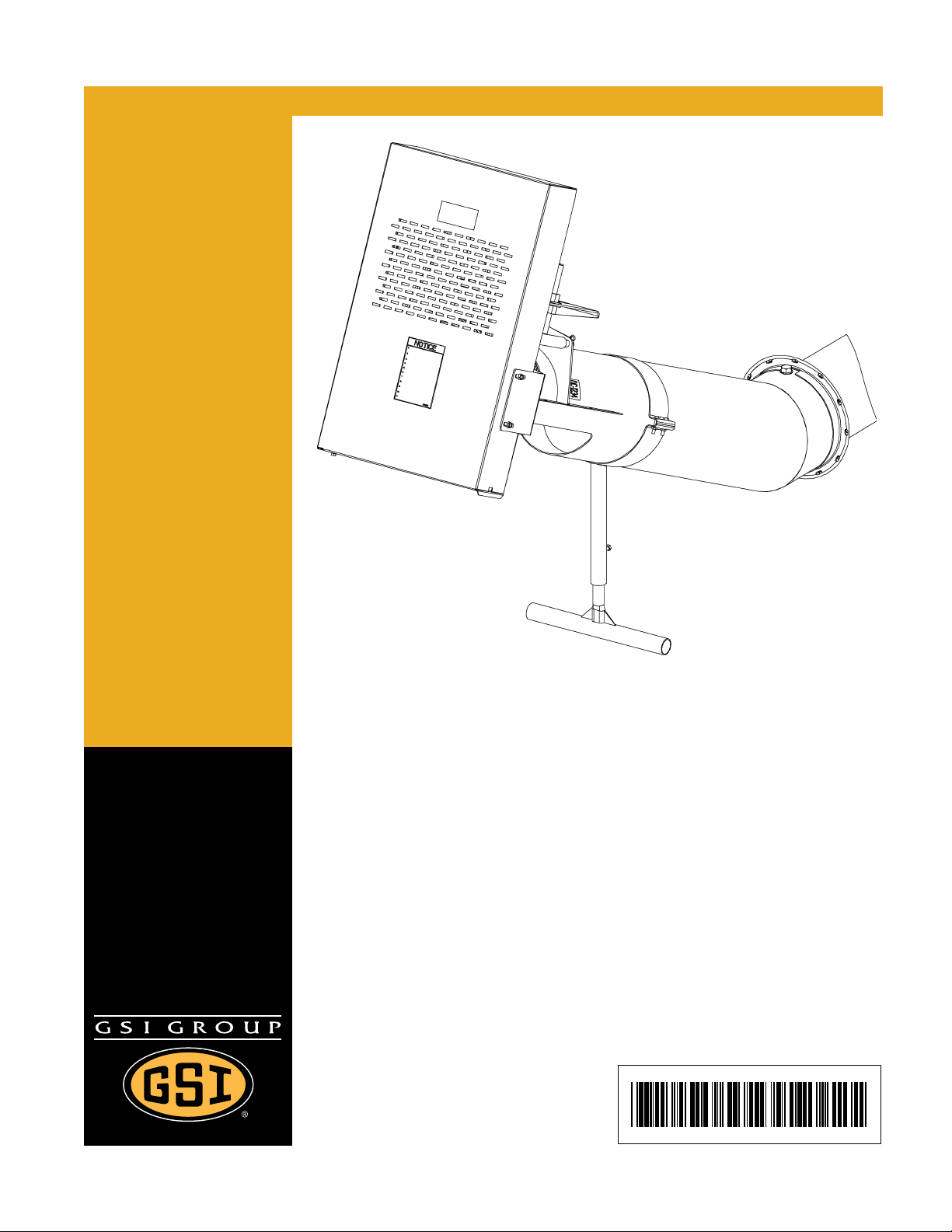
6"-6", 6"-8", 8"-8", 8"-10" and
10"-12" 25° Bin Unloader
Assembly and Operation Manual
PNEG-1430
Date: 02-24-12
Page 2

2 PNEG-1430 6"-6", 6"-8", 8"-8", 8"-10" and 10"-12" 25° Bin Unloader
Page 3

Table of Contents
Contents
Chapter 1 Introduction ..........................................................................................................................................4
Chapter 2 Safety .....................................................................................................................................................5
Safety Guidelines .................................................................................................................................. 5
Safety Instructions ..................... ... .... .......................................... ... ... ..................................................... 6
Operator Qualifications ............................................. .... ... ... ... .... ... ... ... ... .... ... ... ... .................................. 9
Chapter 3 Safety Decals ......................................................................................................................................10
Chapter 4 Assembly ............................................................................................................................................12
Attaching the Adapter Plate (for 6"-8", 8"-10" and 10"-12") ................................................................. 12
Assembling Support Stand .................................................................................................................. 12
Attaching Support Stand to Tube ........................................................................................................ 13
Attaching Flights .................................................................................................................................. 13
Installing the Motor Mount Adjuster ..................................................................................................... 14
Installing the Motor Mount Plate .......................................................................................................... 15
Installing the Belt Guard Brackets ....................................................................................................... 16
Installing the Pulley ...... .......................................... ... .... ... .......................................... ... ...................... 17
Tightening the Lock Collar .................................................................................................................. 17
Installing the Motor (Not Provided) ............................ .................... ................... ................ ................... 18
Installing the Belts .................................. ... ... .... ... ... .......................................... ... .... ............................ 18
Installing the Belt Guard ............................... .... ... ... ... .... ... ... ... .... ......................................................... 19
Chapter 5 Motors .................................................................................................................................................20
Electric Drive Motors ........................................................................................................................... 20
Chapter 6 Start-Up ...............................................................................................................................................21
Perform Pre-Start Checks ............................ .... ... .......................................... ... ... ................................ 21
Start the Auger .................................................................................................................................... 22
Chapter 7 Operation ............................................................................................................................................23
Operate the Auger ............................................................................................................................... 23
Chapter 8 Shut Down ...........................................................................................................................................24
Normal Shut Down .............................................................................................................................. 24
Emergency Shut Down ....................................................... ... .... ... ... ... ... .... ... ... ... .... ............................ 24
Storage Preparation ..................................... .... ... .......................................... ... ... .... ............................ 24
Chapter 9 Maintenance ........................................................................................................................................25
Maintain the Auger .............................................................................................................................. 25
Chapter 10 Parts List ...........................................................................................................................................27
6" to 6" 25° Unloader Parts ................................................................................................................ 28
6" to 8" 25° Unloader Parts ................................................................................................................ 30
8" to 8" 25° Unloader Parts ................................................................................................................ 32
8" to 10" 25° Unloader Parts .............................................................................................................. 34
10" to 12" 25° Unloader Parts ............................................................................................................ 36
Chapter 11 Troubleshooting ...............................................................................................................................38
Chapter 12 Warranty ............................................................................................................................................39
PNEG-1430 6"-6", 6"-8", 8"-8", 8"-10" and 10"-12" 25° Bin Unloader 3
Page 4

1. Introduction
READ THIS MANUAL carefully to learn how to properly use and install equipment. Failure to do so could
result in personal injury or equipment damage.
INSPECT the shipment immediately upon arrival. The customer is responsible for ensuring that all
quantities are correct. The customer should report and note any damage or shortage on the bill of
lading to justify their claim to the transport company.
THIS MANUAL SHOULD BE CONSIDERED a permanent part of your equipment and should be easily
accessible when needed.
This warranty provides you the assurance that the company will back its products when defects appear
within the warranty period. In some circumstances, the company also provides field improvements, often
without charge to the customer, even if the product is out of warranty. Should the equipment be abused,
or modified to change its performance beyond the factory specifications, the warranty will become void
and field improvements may be denied.
4 PNEG-1430 6"-6", 6"-8", 8"-8", 8"-10" and 10"-12" 25° Bin Unloader
Page 5
2. Safety
DANGER
WARNING
CAUTION
NOTICE
This is the safety alert symbol. It is used to alert you
to potential personal injury hazards. Obey all safety
messages that follow this symbol to avoid possible
injury or death.
WARNING indicates a hazardous situation which, if not
avoided, could result in death or serious injury.
CAUTION, used with the safety alert symbol, indicates a
hazardous situation which, if not avoided, could result in
minor or moderate injury.
NOTICE is used to address practices not related to
personal injury.
DANGER indicates a hazardous situation which, if not
avoided, will result in death or serious injury.
Safety Guidelines
This manual contains information that is important for you, the owner/operator, to know and understand.
This information relates to protecting personal safety and preventing equipment problems. It is the
responsibility of the owner/operator to inform anyone operating or working in the area of this equipment
of these safety guidelines. To help you recognize this information, we use the symbols that are defined
below. Please read the manual and pay attention to these sections. Failure to read this manual and its
safety instructions is a misuse of the equipment and may lead to serious injury or death.
PNEG-1430 6"-6", 6"-8", 8"-8", 8"-10" and 10"-12" 25° Bin Unloader 5
Page 6
2. Safety
Follow Safety Instructions
Carefully read all safety messages in this manual and
safety signs on your machine. Keep signs in good
condition. Replace missing or damaged safety signs. Be
sure new equipment components and repair parts include
the current safety signs. Replacement safety signs are
available from the manufacturer.
Learn how to operate the machine and how to use controls
properly. Do not let anyone operate without instruction.
Keep your machinery in proper working condition.
Unauthorized modifications to the machine may impair
the function and/or safety and affect machine life.
If you do not understand any part of this manual or need
assistance, contact your dealer.
Read and Understand Manual
Operate Motor Properly
To avoid serious injury or death, stay away from unit and make sure
everyone is clear of the equipment before starting or operating
the unit.
All electrical connections should be made in accordance with
the National Electric Code. Be sure equipment and bins are
properly grounded.
Do not operate electric motor equipped units until motors are
properly grounded.
Disconnect power on electrical driven units before resetting
motor overloads.
Do not repetitively stop and start the drive in order to free a plugged
condition. Jogging the drive in this manner can damage the
equipment and/or drive components.
Electric Shock Hazard
Safety Instructions
Our foremost concern is your safety and the safety of others associated with this equipment. We want to
keep you as a customer. This manual is to help you understand safe operating procedures and some
problems that may be encountered by the operator and other personnel.
As owner and/or operator, it is your responsibility to know what requirements, hazards, and precautions
exist, and to inform all personnel associated with the equipment or in the area. Safety precautions may be
required from the personnel. Avoid any alterations to the equipment. Such alterations may p roduce a very
dangerous situation where SERIOUS INJURY or DEATH may occur.
This equipment shall be installed in accordance with the current installation codes and applicable
regulations, which should be carefully followed in all cases. Authorities having jurisdiction should be
consulted before installations are made.
6 PNEG-1430 6"-6", 6"-8", 8"-8", 8"-10" and 10"-12" 25° Bin Unloader
Page 7
2. Safety
Prepare for Emergencies
Be prepared if fire starts.
Keep a first aid kit and fire extinguisher handy.
Keep emergency numbers for doctors, ambulance service,
hospital, and fire department near your telephone.
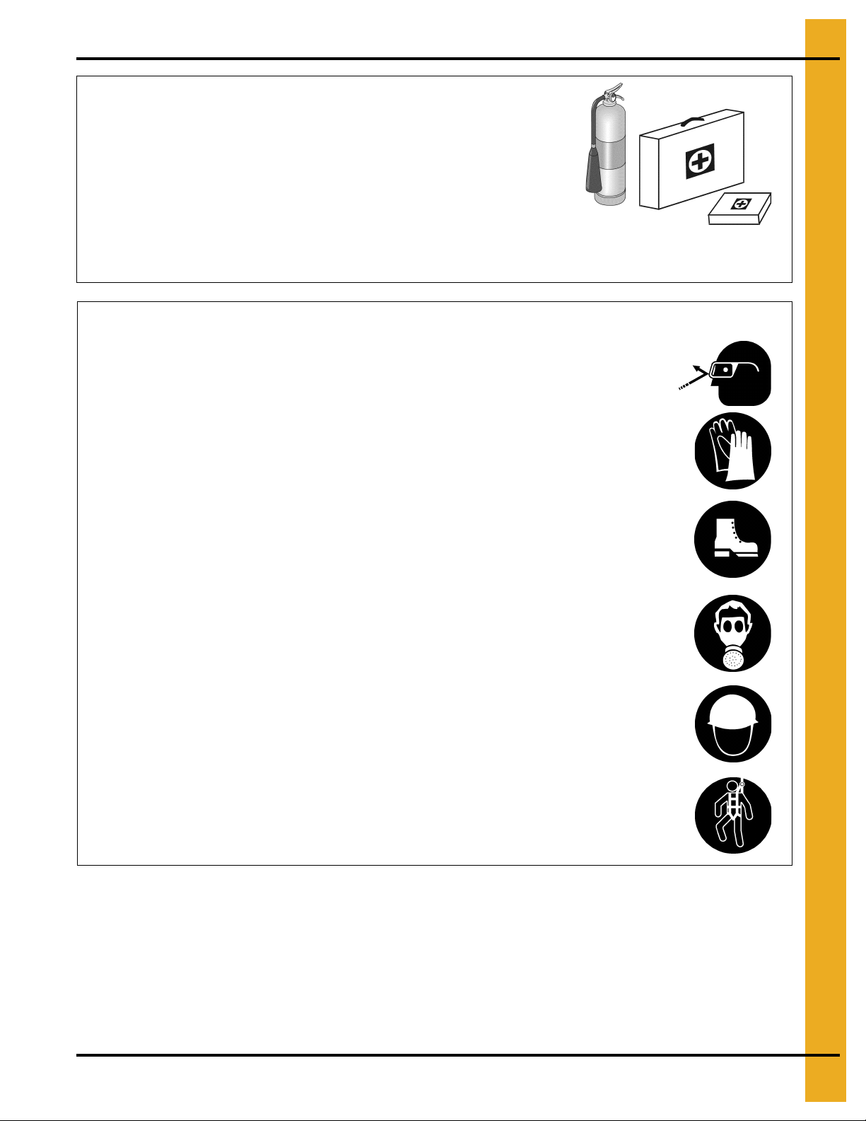
Keep Emergency Equipment
Quickly Accessible
Wear Protective Clothing
Wear close-fitting clothing and safety equipment appropriate
to the job.
Remove all jewelry.
Tie long hair up and back.
Wear safety glasses at all times to protect eyes from debris.
Wear gloves to protect your hands from sharp edges on plastic
or steel parts.
Wear steel-toed boots to help protect your feet from falling
debris. Tuck in any loose or dangling shoestrings.
A respirator may be needed to prevent breathing potentially
toxic fumes and dust.
Wear a hard hat to help protect your head.
Wear appropriate fall protection equipment when working at
elevations greater than six feet (6').
Eye Protection
Gloves
Steel-Toed Boots
Respirator
Hard Hat
Fall Protection
PNEG-1430 6"-6", 6"-8", 8"-8", 8"-10" and 10"-12" 25° Bin Unloader 7
Page 8

2. Safety
Operate Unload Equipment Properly
• Untrained operators subject themselves and others to SERIOUS INJURY
or DEATH. NEVER allow untrained personnel to operate this equipment.
• NEVER work alone.
• Keep children and other unqualified personnel out of the working
area at ALL times. Refer to the Start-Up section of this manual for
diagrams of the work area.
• Make sure ALL equipment is locked in position before operating.
• NEVER start equipment until ALL persons are clear of the work area.
• Keep hands and feet away from the auger intake and other moving parts.
• NEVER attempt to assist machinery operation or to remove trash from equipment while
in operation.
• Be sure all operators are adequately rested and prepared to perform all functions of operating
this equipment.
• NEVER allow any person intoxicated or under the influence of alcohol or drugs to operate
the equipment.
• Make sure someone is nearby who is aware of the proper shut down sequence in the event of an
accident or emergency.
• ALWAYS think before acting. NEVER act impulsively around the equipment.
• NEVER allow anyone inside a bin, truck or wagon which is being unloaded by an auger or
conveyor. Flowing grain can trap and suffocate in seconds.
• Use ample overhead lighting after sunset to light the work area.
• Keep area around intake free of obstacles such as electrical cords, blocks, etc., that might
trip workers.
• NEVER drive, stand or walk under the equipment.
• Use caution not to hit the auger when positioning the load.
• ALWAYS lock out ALL power to the equipment when finished unloading a bin.
• Be aware of pinch points. A pinch point is a narrow area between two surfaces that is likely to trap
or catch objects and so is a potential safety hazard.
Operate Unload
Equipment Safely
8 PNEG-1430 6"-6", 6"-8", 8"-8", 8"-10" and 10"-12" 25° Bin Unloader
Page 9

2. Safety
Operator Qualifications
A. The User/Operator must be competent and experienced to operate auger equipment. Anyone who
works with or around augers must have good common sense in order to be qualified. T hese persons
must also know and meet all other qualifications, such as:
i. Any person who has not read and/or does not understand all operation and safety procedures
is not qualified to operate any auger systems.
ii. Certain regulations apply to personnel operating power machinery. Personnel under the age of
18 years may not operate power machinery, including augers. It is your responsibility, as owner
and/or supervisor, to know what these regulations are in your area or situation.
iii. Unqualified or incompetent persons are to remain out of the work area.
iv. O.S.H.A. (Occupational Safety and Health Administration) regulations state: “At the time of
initial assignment and at least annually thereafter, the employer shall instruct every employee
in the safe operation and servicing of all equipment with which the employee is, or will be
involved”. (Federal Occupational Safety and Health Standards for Agriculture. Subpart D,
Section 1928.57 (a) (6)).
B. As a requirement of O.S.H.A., it is necessary for the employer to train the employee in the safe
operating and safety procedures for this auger. The sign-off sheet is provided for your convenience
and personal record keeping. All unqualified persons are to stay out of the work area at all times. It
is strongly recommended that another qualified person who knows the shut down procedure is in the
area in the event of an emergency.
Date Employee Name Supervisor Name
PNEG-1430 6"-6", 6"-8", 8"-8", 8"-10" and 10"-12" 25° Bin Unloader 9
Page 10
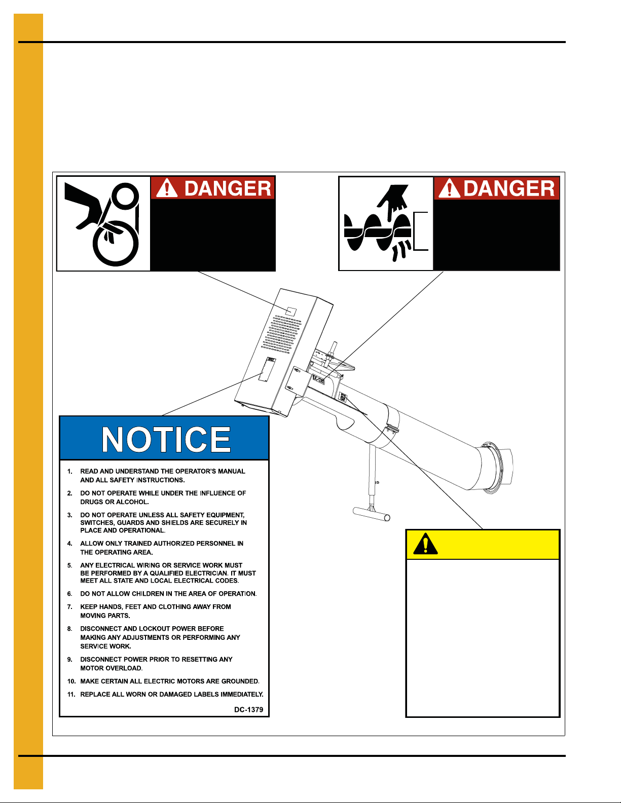
3. Safety Decals
DC-994
DC-1381
DC-1234
DC-1379
SHEAR POINT
Keep clear of rotating auger and
moving parts.
Do not remove or modify guards.
Disconnect and lock out power
before servicing.
Failure to do so will result in
serious INJURY or DEATH.
DC-1381
SHEAR POINT
Keep hands clear of moving
parts. Do not operate with
guard removed. Disconnect
and lockout power before
servicing.
DC-994
Check components shown below to ensure that the safety decals are in place and in good co ndition. If a
decal cannot be easily read for any reason or has been painted over, replace it immediately. Contact you r
dealer or the manufacturer to order a replacement decal free of charge.
Contact:
The GSI Group
1004 E. Illinois St.
Assumption, IL. 62510
Phone: 1-217-226-4421
CAUTION
FAILURE TO PROPERLY SELECT,
INSTALL OR MAINTAIN AN AUGER, ITS
DRIVE OR OTHER COMPONENTS CAN
RESULT IN DANGEROUS OPERATION.
THIS EQUIPMENT IF IMPROPERLY
SELECTED, INSTALLED OR
MAINTAINED MAY FAIL AND COULD
RESULT IN SERIOUS INJURY OR
PROPERTY DAMAGE.
CHECK PRODUCT LITERATURE AND
EQUIPMENT MANUFACTURER’S
LITERATURE OR CALL THE FACTORY
FOR FURTHER INFORMATION.
10 PNEG-1430 6"-6", 6"-8", 8"-8", 8"-10" and 10"-12" 25° Bin Unloader
DC-1234
Page 11

3. Safety Decals
A. DANGER Sign No. DC-1395 was supplied with your bin unloading equipment. This safety sign
should be applied to the side of the bin near the bin opening, so it will be viewed by people
entering into the bin storage building. Do not cover any safety signs or any other signs that are
already there.
B. If the safety sign location suggested is not in full view because of equipment modifications, other
equipment in the area or any reason, then locate the safety sign in a more suitable location.
C. Be certain the surface is clean, dry and free of dirt and oil. Peel paper backing from decals and stick
into place. The adhesive backing will bond on contact.
NOTE: Please remember, safety signs provide important safety information for people working near bin
unloading equipment that is in operation.
NOTE: If the Safety Sign cannot be easily read for any reason or has been painted over, replace it
immediately. Additional Safety Signs may be obtained free of charge from your dealer, distributo r
or ordered from the factory.
Order SAFETY SIGN NO. DC-1395
PNEG-1430 6"-6", 6"-8", 8"-8", 8"-10" and 10"-12" 25° Bin Unloader 11
Page 12
4. Assembly
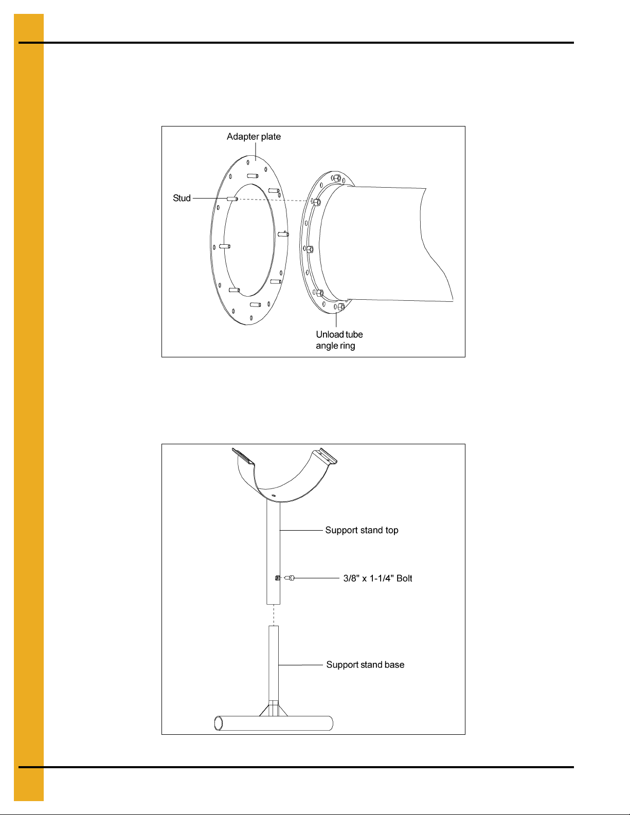
Attaching the Adapter Plate (for 6"-8", 8"-10" and 10"-12")
1. Align studs on adapter plate with the holes on the unload tube’s angle ring.
2. Insert studs through the holes and fasten using nuts from tube end plate. (See Figure 4A.)
Figure 4A
Assembling Support Stand
1. Insert support stand base into support stand top and secure with 3/8" x 1-1/4" bolt. (See Figure 4B.)
Figure 4B
12 PNEG-1430 6"-6", 6"-8", 8"-8", 8"-10" and 10"-12" 25° Bin Unloader
Page 13

4. Assembly
(See Chart for Bolt Sizes on Page 16.)
Attaching Support Stand to Tube
1. Place support stand and half band around tube and secure together with 5/16" bolts and serrated
flange nuts. (See Figure 4C.)
Figure 4C
Attaching Flights
1. Pull bin unload flight out of unload tube approximately one foot (1').
2. Remove bearing connecting stub bolts and nuts from connecting stub.
3. Position 25° unloader assembly in-line with bin tube.
4. Align holes in unload flight with holes in bearing connecting stub and slide flight onto stub.
5. With holes aligned, secure with bearing connecting stub bolts and nuts that were removed in Step 2.
(See Figure 4D.)
PNEG-1430 6"-6", 6"-8", 8"-8", 8"-10" and 10"-12" 25° Bin Unloader 13
Figure 4D
Page 14

4. Assembly
Installing the Motor Mount Adjuster
1. Place motor mount adjuster between the head plate and back plate on the discharge tube.
2. Insert pivot rod through the tube plates and motor mount adjuster. Secure in place with two (2)
3/16" x 2" cotter pins. (See Figure 4E.)
Figure 4E
14 PNEG-1430 6"-6", 6"-8", 8"-8", 8"-10" and 10"-12" 25° Bin Unloader
Page 15

4. Assembly
Installing the Motor Mount Plate
1. Secure one of the motor mount adjustment nuts and one of the motor mount adjustment washers
approximately 3/4" of the way down the motor mount adjuster’s threaded shaft.
2. Once the nut and washer are secure, slip the motor mount plate over the a djuster and align the pivot
holes with the pivot tube. (See Figure 4F.)
Figure 4F
3. Slide the motor mount pivot rod through the pivot tube on the discharge tube.
4. When the pivot rod begins to extend through the pivot tube, install the spacers BETWEEN the back
plate and the inner face of the motor mount plate. (See Figure 4G.)
Figure 4G
5. Secure pivot rod with two (2) 3/16" x 2" cotter pins.
NOTE: The number of spacers will vary depending on size of unloader.
PNEG-1430 6"-6", 6"-8", 8"-8", 8"-10" and 10"-12" 25° Bin Unloader 15
Page 16

4. Assembly
(See Chart for Bolt Sizes.)
Installing the Belt Guard Brackets
1. Align the holes on the bearing plate with the slots on the belt guard mounting brackets.
2. Secure the brackets with proper bolts, flat washers and serrated flange nuts. (See Chart below and
Figure 4H.)
Figure 4H
Belt Guard Mounting Bracket Bolt
Part # Bolt Size Description
S-1 196 6" to 6", 6" to 8" and 8" to 8" 5/16"-18 x 1" Grade 5 Bolt
S-2071 8" to 10" and 10" to 12" 3/8"-16 x 1-1/4" Grade 5 Bolt
NOTE: DO NOT tighten the bolts completely. The brackets will need to be rotated to align the slot in the
belt guard with the shafts on the motor and flight.
16 PNEG-1430 6"-6", 6"-8", 8"-8", 8"-10" and 10"-12" 25° Bin Unloader
Page 17

4. Assembly
Installing the Pulley
1. Place and position the key into the keyway located on the drive shaft.
2. Place the pulley onto the drive shaft with the set screw side of the pulley facing away from the bearing
plate. (See Figure 4I.) Position the pulley so that it is as close to the lock collar as possible, but
without touching it.
3. Once the pulley is appropriately positioned, tighten the set screw with a hex head wrench to secure
it to the drive shaft. (See Figure 4I.)
Figure 4I
Tightening the Lock Collar
1. Use a punch and hammer to drive the lock collar clockwise or in the same direction as the shaft
rotation. Once the lock collar is set in place, use a hex head wrench to tighten the lock collar by
tightening the set screw.
NOTE: If the lock collar is not turned far enough, the set screw will not lock it into place.
PNEG-1430 6"-6", 6"-8", 8"-8", 8"-10" and 10"-12" 25° Bin Unloader 17
Page 18

4. Assembly
Installing the Motor (Not Provided)
1. Attach the motor to the motor mount plate using appropriate bolts, lock washers and hex nuts.
(See Motor Bolt Chart below.)
2. Install pulley onto motor shaft making sure that it is aligned with the flight pulley. It may be necessary
to move spacers to gain shaft alignment. (See Figure 4J.)
Installing the Belts
1. Place the belts on the pulleys.
Figure 4J
Motor Bolt Chart
Motor Size Hex Bolt Size Qty
56
5/16"-18 x 1-1/4" 4143T
145T
182T
184T
3/8"- 16 x 1-1/4" 4
213T
215T
254T
1/2"-13 x 1-3/4" 4
256T
2. Screw the lower motor mount adjustment nut upward, thereby raising the motor mount plate and
putting tension on the belts.
3. Once the desired tension is reached, tighten the upper motor mount adjustment nut down onto the
motor mount plate to lock it into place. (See Figure 4K on Page 19.)
18 PNEG-1430 6"-6", 6"-8", 8"-8", 8"-10" and 10"-12" 25° Bin Unloader
Page 19

4. Assembly
Installing the Belt Guard
1. With the belts properly tensioned, remove the bottom belt guard cover and slip belt guard down over
motor shaft.
2. Bolt the belt guard to the belt guard mounting brackets. Note that the brackets should still be loose
at this time.
3. Align the motor shaft and the flight drive shaft in the belt guard’s slot, making sure that the belt guard
DOES NOT contact either pulley or shaft and tighten down the belt guard mounting brackets to the
bearing plate. (See Figure 4K.)
4. Once the brackets are tightened, slide the bottom cover back into place and secure with supplied bolt.
Figure 4K
PNEG-1430 6"-6", 6"-8", 8"-8", 8"-10" and 10"-12" 25° Bin Unloader 19
Page 20

5. Motors
WARNING
Electrical controls and wiring should be installed by a qualified electrician. The
motor disconnect switches and conductor cables should comply with the
National Electrical Code and any local codes which apply. Reset and motor
starting stations should be located so that the operator can see that all personnel
are clear of the equipment.
WARNING
Disconnect and lock out power before resetting motor overloads. Make certain
electric motors are grounded.
Electric Drive Motors
A. Knowing the bin size and the length of flighting to be used in the unloading tube is necessary to
determine how much horsepower is required for the job.
B. Use the Chart below to determine the size of motor required. Use a larger motor when encountering
high moisture or when high capacity is required.
25°
Horsepower
6" 2 2 3 3 3 3 5 5 - 8" 3 3 5 5 5 7-1/2 7-1/2 7-1/2 7-1/2 7-1/2
10" - - - 5 5 7-1/2 7-1/2 7-1/2 10 10
15' 18' 21' 24' 27' 30' 33' 36' 42' 48'
Grain Bin Diameter
NOTE: For high capacity or high moisture, use one size larger motor.
LONGER BELT NOTE: Longer belts may be required when using larger framed motors due to high
capacity or high moisture applications.
C. The following horsepower recommendations are for augering relatively dry grain. Use an electric
motor of the proper size that operates at 1750 RPM. Motor pulleys are not furnished with the auger.
D. A magnetic starter should be used for the operator’s protection and for the protection of the motor.
This helps to protect the operator against accidental re-start caused by power interruption, conductor
fault, low voltage, circuit interruption or motor overload. Therefore, the motor must be restarted
manually. If using a motor with built-in thermal overload protection, make sure this type of motor has
a manual reset.
20 PNEG-1430 6"-6", 6"-8", 8"-8", 8"-10" and 10"-12" 25° Bin Unloader
Page 21

6. Start-Up
Failure to perform any or all of these pre-start checks may cause damage to the
equipment and/or cause SERIOUS INJURY or DEATH to those in the work area.
Failure to perform any or all of these pre-start checks may also be a misuse of the
equipment. Any misuse of the equipment may void the warranty.
ALWAYS keep ALL guards and shields in place, until all the power is
disconnected and locked out.
DANGER
WARNING
Make certain ONLY trained operators are in the work area before operating or
moving the machine. Two (2) people must always be in a position where the
operation of the equipment can be monitored.
Perform Pre-Start Checks
DANGER
A. Make sure ALL belts are tensioned properly.
B. Make sure ALL shields are in place and that the belt(s) and pulley(s) are able to move freely.
C. Inspect the drive unit for any problems or potential problems.
D. Be aware of any emergency shut down procedures. Two (2) people must always be in a position
where the operation of the equipment can be monitored.
E. Before starting the auger for the first time, make sure that all parts are assembled correctly according
to the instructions in this manual.
PNEG-1430 6"-6", 6"-8", 8"-8", 8"-10" and 10"-12" 25° Bin Unloader 21
Page 22

6. Start-Up
CAUTION
DO NOT start or stop the auger while it is under load. Doing so may cause the
auger to jam.
Failures may occur if the auger is run full before it has been “polished” during the
“break-in” period.
CAUTION
NEVER operate the auger empty. Operating augers empty for any length of time
will cause excessive wear.
NEVER operate the auger at speeds higher than recommended. Auger flight speed
in excess of recommended speed causes excessive wear.
CAUTION
Be aware of any unusual vibration or noises during the initial start-up and
“break-in” period. If anything unusual is detected, immediately shut down the
auger and disconnect and lock out the power supply before servicing.
CAUTION
Start the Auger
A. Start the auger.
B. Run the auger through a “break-in” period if it is being used for the first time or for the first time of
the season.
C. Polish the flighting by running the auger at partial capacity until it is smooth, before attempting
to run it at full capacity.
22 PNEG-1430 6"-6", 6"-8", 8"-8", 8"-10" and 10"-12" 25° Bin Unloader
Page 23

7. Operation
WARNING
Be alert for any unusual vibrations, noises and the loosening of any fasteners. If
anything unusual is detected, immediately shut down the auger, disconnect and
lock out the power source before servicing.
Operate the Auger
NOTE: The auger capacity can fluctuate greatly under varying conditions. Moisture content, different
commodities, amount of foreign matter and speeds all play a part in the performance of the auger.
For example, 25% moisture may cut capacity by as much as 40% under some conditions.
A. Make certain there are at least two (2) people in the work area to monitor operations at all times.
B. Visually inspect the auger periodically during operation.
C. Consideration should be given to the proper size auger for a batch drying or any intermittent type
operations. When augers are stopped and re-started under full load, it may result in damage to the
auger. Using a larger diameter auger and reducing its load level is generally preferable to subjecting
a smaller diameter auger to big loads. If an auger is kept from absolute filling, it will make start-up
easier and it will convey more efficiently.
PNEG-1430 6"-6", 6"-8", 8"-8", 8"-10" and 10"-12" 25° Bin Unloader 23
Page 24

8. Shut Down
NEVER start the equipment under load. Doing so may cause damage. This type of
damage is considered a misuse of the equipment. Any misuse of the equipment
may void the warranty.
Normal Shut Down
A. Before shutting down the unit, be sure the hoppers and augers are empty.
B. Disconnect and lock out the power source before leaving the work area.
Emergency Shut Down
A. Know how to shut down the auger in case of an emergency.
B. Do not re-start the auger when it is under load.
C. Close the bin well control gates.
D. Re-connect and unlock the power source.
E. Clear the auger gradually until there is no grain and there are no obstructions.
CAUTION
Storage Preparation
A. Close all wells to the discharge auger.
B. Be sure the unload tube is empty.
C. Shut down the auger.
D. Make sure all fasteners are tight.
24 PNEG-1430 6"-6", 6"-8", 8"-8", 8"-10" and 10"-12" 25° Bin Unloader
Page 25

9. Maintenance
ALWAYS shut down and disconnect the power supply before adjusting,
servicing or cleaning the equipment.
Maintain the Auger
DANGER
A. Use caution when repairing or replacing equipment parts.
B. Make sure ALL decals are legible and tightly attached to th e auger. If necessary, replace them FREE
OF CHARGE by contacting your dealer or the manufacturer.
C. Ensure that ALL electric motors, etc., are operating at the proper speed.
D. Maintain proper adjustments on the belt(s).
E. Mount controls for any electric motors at a safe distance from the machine and in a location
accessible in case of an emergency.
F. Make sure ALL electrical wiring is not damaged and that it meets proper wiring codes.
G. Make sure ALL components are in good working condition before use.
H. Check the auger flighting to make sure it is in good working condition.
I. Check the internal bearing bracket, bearing and universal joint to make sure they are in good
working condition.
J. Grease bearing at least two (2) times each season.
PNEG-1430 6"-6", 6"-8", 8"-8", 8"-10" and 10"-12" 25° Bin Unloader 25
Page 26

NOTES
26 PNEG-1430 6"-6", 6"-8", 8"-8", 8"-10" and 10"-12" 25° Bin Unloader
Page 27

1. 6" to 6" 25° Unloader Parts - (See Pages 28-29.)
2. 6" to 8" 25° Unloader Parts - (See Pages 30-31.)
3. 8" to 8" 25° Unloader Parts - (See Pages 32-33.)
4. 8" to 10" 25° Unloader Parts - (See Pages 34-35.)
5. 10" to 12" 25° Unloader Parts - (See Pages 36-37.)
10. Parts List
PNEG-1430 6"-6", 6"-8", 8"-8", 8"-10" and 10"-12" 25° Bin Unloader 27
Page 28

10. Parts List
6" to 6" 25° Unloader Parts
28 PNEG-1430 6"-6", 6"-8", 8"-8", 8"-10" and 10"-12" 25° Bin Unloader
Page 29

6" to 6" 25° Unloader Parts List
Ref # Part # Description
2 GK5706 1" x 7-7/8" Bearing Connecting Stub
3 S-6762 3/8"-16 x 2-1/2" Grade 5 Bearing Connecting Stub Bolt
4 S-8251 3/8"-16 Bearing Connecting Stub Stover Nut
5 S-8397 5/16" x 1-3/4" U-Joint Rolled Pin
7 GC06392 Hanger Bearing
8 GK1267 1" x 6" Connecting Stub
9 GK1266 1" Bore x 5" Long U-Joint
10 S-7886 5/8"-11 x 1-3/4" Grade 8 Hanger Bearing Bolt
11 S-3208 5/8" Hanger Bearing Lock Washer
12 GK7072 6" 25° Unload Tube Assembly
13 S-2741 5/16"-18 x 1-1/2" Grade 5 Stand Connecting Band Bolt
14 GK1 122 6" x 4" 12 Gauge Half Band
15 S-866 3/4" Motor Mount Adjustment Flat Washer
16 S-234 3/4"-10 Motor Mount Adjustment Hex Nut
17 GK7052 Motor Mount Plate
18 GK7060 Motor Mount Adjustment Weldment
20 S-6994 3/16" x 2" Cotter Pin
21 GK7058 Motor Mount Plate Pivot Rod
23 GK7005 Belt Guard
24 GK1321 12" Diameter x 1" Bore 2 Belt Sheave
25 S-4513 1/4" x 2" Sheave Key
26 GK7062 Belt Guard Mounting Brackets
27 S-1196 5/16"-18 x 1" Grade 5 Belt Guard Mounting Bracket Bolt
28 S-845 5/16" Belt Guard Mounting Bracket Flat Washer
29 S-9065 3/8"-16 x 1" Grade 5 Bolt
30 S-3611 5/16"-18 Bearing Plate Serrated Flange Nut
31 GK2825 Support Stand Top
32 GK1277 Support Stand Base
33 S-3611 5/16"-18 Serrated Flange Nut
34 S-6762 3/8"-16 x 2-1/2" Grade 5 Flight Connection Bolt
35 GK2025 1" x 10" Drive Shaft
36 S-8251 3/8"-16 Flight Connection Stover Nut
37 S-860 7/16"-14 Bearing Hex Nut
38 S-7014 7/16" Bearing Lock Washer
39 GK1049 1" Two (2) Hole Flange with Lock Collar (Bearing with Flange)
40 S-1196 5/16"-18 x 1" Grade 5 Bearing Plate Bolt
41 GK7061 Bearing Plate
42 S-3886 7/16"-14 x 1-1/4" Grade 5 Bearing Bolt
43 GK2827 6" 25° Weldment Discharge Flight
44 S-2071 3/8"-16 x 1-1/4" Grade 5 Bolt
45 GK1323 B48 V-Belt
10. Parts List
PNEG-1430 6"-6", 6"-8", 8"-8", 8"-10" and 10"-12" 25° Bin Unloader 29
Page 30

10. Parts List
6" to 8" 25° Unloader Parts
30 PNEG-1430 6"-6", 6"-8", 8"-8", 8"-10" and 10"-12" 25° Bin Unloader
Page 31

6" to 8" 25° Unloader Parts List
Ref # Part # Description
1 GK1280 Adapter Plate
2 GK7241 1" x 8-1/2" Bearing Connecting Stub
3 S-6762 3/8"-16 x 2-1/2" Grade 5 Bearing Connecting Stub Bolt
4 S-8251 3/8"-16 Bearing Connecting Stub Stover Nut
5 S-8397 5/16" x 1-3/4" U-Joint Rolled Pin
7 GC06394 Hanger Bearing
8 GK1267 1" x 6" Connecting Stub
9 GK1266 1" Bore x 5" Long U-Joint
10 S-7886 5/8"-11 x 1-3/4" Grade 8 Hanger Bearing Bolt
1 1 S-3208 5/8" Hanger Bearing Lock Washer
12 GK7073 8" 25° Unload Tube Assembly
13 S-2741 5/16"-18 x 1-1/2" Grade 5 Stand Connecting Band Bolt
14 GK1059 8" x 4" 12 Gauge Half Band
15 S-7835 1" Motor Mount Adjustment Flat Washer
16 S-240 1"-8 Motor Mount Adjustment Hex Nut
17 GK6986 Motor Mount Plate
18 GK6942 Motor Mount Adjustment Weldment
19 GK7012 Motor Mount Adjustment Pivot Rod
20 S-6994 3/16" x 2" Cotter Pin
21 GK7013 Motor Mount Plate Pivot Rod
22 GK7014 Pivot Spacer Tube
23 GK7005 Belt Guard
24 GK1335 12" Diameter x 1-1/4" Bore 2 Belt Sheave
25 S-4513 1/4" x 2" Sheave Key
26 GK7006 Belt Guard Mounting Brackets
27 S-1196 5/16"-18 x 1" Grade 5 Belt Guard Mounting Bracket Bolt
28 S-845 5/16" Belt Guard Mounting Bracket Flat Washer
29 S-9065 3/8"-16 x 1" Grade 5 Bolt
30 S-3611 5/16"-18 Bearing Plate Serrated Flange Nut
31 GK1278 Support Stand Top
32 GK1277 Support Stand Base
33 S-3611 5/16"-18 Serrated Flange Nut
34 S-8316 7/16"-14 x 3" Grade 8 Flight Connection Bolt
35 GK1331 1-1/4" x 10-1/2" Drive Shaft
36 S-8317 7/16"-14 Flight Connection Stover Nut
37 S-7510 1/2"-13 Bearing Hex Nut
38 S-236 1 / 2" B ea ri n g Lock Washer
39 GK1330 1-1/4" Two (2) Hole Flange with Lock Collar (Bearing with Flange)
40 S-1196 5/16"-18 x 1" Grade 5 Bearing Plate Bolt
41 GK6987 Bearing Plate
42 S-8760 1/2"-13 x 1-1/2" Grade 5 Bearing Bolt
43 GK1268 8" 25° Weldment Discharge Flight
44 S-2071 3/8"-16 x 1-1/4" Grade 5 Bolt
45 GK1952 B50 V-Belt
10. Parts List
PNEG-1430 6"-6", 6"-8", 8"-8", 8"-10" and 10"-12" 25° Bin Unloader 31
Page 32

10. Parts List
8" to 8" 25° Unloader Parts
32 PNEG-1430 6"-6", 6"-8", 8"-8", 8"-10" and 10"-12" 25° Bin Unloader
Page 33

8" to 8" 25° Unloader Parts List
Ref # Part # Description
2 GK1283 1-1/4" x 7-7/8" Bearing Connecting Stub
3 S-8316 7/16"-14 x 3" Grade 5 Bearing Connecting Stub Bolt
4 S-8317 7/16"-14 Bearing Connecting Stub Stover Nut
5 S-8397 5/16" x 1-3/4" U-Joint Rolled Pin
7 GC06394 Hanger Bearing
8 GK1267 1" x 6" Connecting Stub
9 GK1266 1" Bore x 5" Long U-Joint
10 S-7886 5/8"-11 x 1-3/4" Grade 8 Hanger Bearing Bolt
11 S-3208 5/8" Hanger Bearing Lock Washer
12 GK7073 8" 25° Unload Tube Assembly
13 S-2741 5/16"-18 x 1-1/2" Grade 5 Stand Connecting Band Bolt
14 GK1059 8" x 4" 12 Gauge Half Band
15 S-7835 1" Motor Mount Adjustment Flat Washer
16 S-240 1 "-8 Motor Mount Adjustment Hex Nut
17 GK6986 Motor Mount Plate
18 GK6942 Motor Mount Adjustment Weldment
19 GK7012 Motor Mount Adjustment Pivot Rod
20 S-6994 3/16" x 2" Cotter Pin
21 GK7013 Motor Mount Plate Pivot Rod
22 GK7014 Pivot Spacer T ube
23 GK7005 Belt Guard
24 GK1335 12" Diameter x 1-1/4" Bore 2 Belt Sheave
25 S-4513 1/4" x 2" Sheave Key
26 GK7006 Belt Guard Mounting Brackets
27 S-1196 5/16"-18 x 1" Grade 5 Belt Guard Mounting Bracket Bolt
28 S-845 5/16" Belt Guard Mounting Bracket Flat Washer
29 S-9065 3/8"-16 x 1" Grade 5 Bolt
30 S-3611 5/16"-18 Bearing Plate Serrated Flange Nut
31 GK1278 Support Stand Top
32 GK1277 Support Stand Base
33 S-3611 5/16"-18 Serrated Flange Nut
34 S-8316 7/16"-14 x 3" Grade 8 Flight Connection Bolt
35 GK1331 1-1/4" x 10-1/2" Drive Shaft
36 S-8317 7/16"-14 Flight Connection Stover Nut
37 S-7510 1/2"-13 Bearing Hex Nut
38 S-236 1/2" Bearing Lock Washer
39 GK1330 1-1/4" Two (2) Hole Flange with Lock Collar (Bearing with Flange)
40 S-1196 5/16"-18 x 1" Grade 5 Bearing Plate Bolt
41 GK6987 Bearing Plate
42 S-8760 1/2"-13 x 1-1/2" Grade 5 Bearing Bolt
43 GK1268 8" 25° Weldment Discharge Flight
44 S-2071 3/8"-16 x 1-1/4" Grade 5 Bolt
45 GK1952 B50 V-Belt
10. Parts List
PNEG-1430 6"-6", 6"-8", 8"-8", 8"-10" and 10"-12" 25° Bin Unloader 33
Page 34

10. Parts List
8" to 10" 25° Unloader Parts
34 PNEG-1430 6"-6", 6"-8", 8"-8", 8"-10" and 10"-12" 25° Bin Unloader
Page 35

8" to 10" 25° Unloader Parts List
Ref # Part # Description
1 GK1298 Adapter Plate
2 GK7240 1-1/4" x 9" Bearing Connecting Stub
3 S-8316 7/16"-14 x 3" Grade 5 Bearing Connecting Stub Bolt
4 S-8317 7/16"-14 Bearing Connecting Stub Stover Nut
5 S-7245 3/8" x 2-1/2" U-Joint Rolled Pin
7 GC06396 Hanger Bearing
8 GK1290 1-1/4" x 6-1/2" Connecting Stub
9 GK1291 1-1/4" Bore x 7" Long U-Joint
10 S-7886 5/8"-11 x 1-3/4" Grade 8 Hanger Bearing Bolt
1 1 S-3208 5/8" Hanger Bearing Lock Washer
12 GK7074 10" 25° Unload Tube Assembly
13 S-2741 5/16"-18 x 1-1/2" Grade 5 Stand Connecting Band Bolt
14 GK1301 10" x 4" 12 Gauge Half Band
15 S-7835 1" Motor Mount Adjustment Flat Washer
16 S-240 1"-8 Motor Mount Adjustment Hex Nut
17 GK6986 Motor Mount Plate
18 GK6942 Motor Mount Adjustment Weldment
19 GK7012 Motor Mount Adjustment Pivot Rod
20 S-6994 3/16" x 2" Cotter Pin
21 GK7013 Motor Mount Plate Pivot Rod
22 GK7014 Pivot Spacer Tube
23 GK7005 Belt Guard
24 GK1345 15" Diameter x 1-1/2" Bore 2 Belt Sheave
24 GK1304 15" Diameter x 1-1/2" Bore 3 Belt Sheave
25 S-9181 3/8" x 3" Sheave Key
26 GK7018 Belt Guard Mounting Brackets
27 S-2071 3/8"-16 x 1-1/4" Grade 5 Belt Guard Mounting Bracket Bolt
28 S-248 3/8" Belt Guard Mounting Bracket Flat Washer
29 S-9065 3/8"-16 x 1" Grade 5 Bolt
30 S-968 3/8"-16 Bearing Plate Serrated Flange Nut
31 GK1300 Support Stand Top
32 GK1277 Support Stand Base
33 S-3611 5/16"-18 Serrated Flange Nut
34 S-8316 7/16"-14 x 3" Grade 8 Flight Connection Bolt
34 S-8314 1/2"-13 x 3-1/2" Grade 8 Flight Connection Bolt
35 GK1289 1-1/2" x 11-1/2" Drive Shaft
36 S-8317 7/16"-14 Flight Connection Stover Nut
36 S-8315 1/2"-13 Flight Connection Stover Nut
37 S-7510 1/2"-13 Bearing Hex Nut
38 S-236 1/2" Bearing Lock Washer
39 GK1343 1-1/2" Four (4) Hole Flange with Lock Collar (Bearing with Flange)
40 S-7469 3/8"-16 x 1" Grade 5 Bearing Plate Bolt
41 GK7017 Bearing Plate
42 S-8760 1/2"-13 x 1-1/2" Grade 5 Bearing Bolt
43 GK6396 10" 25° Weldment Discharge Flight
44 S-2071 3/8"-16 x 1-1/4" Grade 5 Bolt
45 GK1346 B57 V-Belt
10. Parts List
PNEG-1430 6"-6", 6"-8", 8"-8", 8"-10" and 10"-12" 25° Bin Unloader 35
Page 36

10. Parts List
10" to 12" 25° Unloader Parts
36 PNEG-1430 6"-6", 6"-8", 8"-8", 8"-10" and 10"-12" 25° Bin Unloader
Page 37

10" to 12" 25° Unloader Parts List
Ref # Part # Description
1 GK2013 Adapter Plate
2 GK7242 1-1/2" x 9" Bearing Connecting Stub
3 S-8314 1/2"-13 x 3-1/2" Grade 5 Bearing Connecting Stub Bolt
4 S-8315 1/2"-13 Bearing Connecting Stub Stover Nut
5 S-7245 3/8" x 2-1/2" U-Joint Rolled Pin
6 S-9169 1/4" x 1-1/2" U-Joint Square Key
7 GC06398 Hanger Bearing
8 GK2008 1-1/4" to 2" x 6-1/2" Connecting Stub
9 GK2009 1-1/4" Bore with Key Way x 7" Long (U-Joint)
10 S-869 3/4"-10 x 2" Grade 8 Hanger Bearing Bolt
11 S-233 3/4" Hanger Bearing Lock Washer
12 GK7075 12" 25° Unload Tube Assembly
13 S-7149 5/16"-18 x 1-3/4" Grade 5 Stand Connecting Band Bolt
14 GK2014 12" x 4" 12 Gauge Half Band
15 S-7835 1" Motor Mount Adjustment Flat Washer
16 S-240 1 "-8 Motor Mount Adjustment Hex Nut
17 GK6986 Motor Mount Plate
18 GK6942 Motor Mount Adjustment Weldment
19 GK7012 Motor Mount Adjustment Pivot Rod
20 S-6994 3/16" x 2" Cotter Pin
21 GK7013 Motor Mount Plate Pivot Rod
22 GK7014 Pivot Spacer T ube
23 GK7068 Belt Guard
24 GK1345 15" Diameter x 1-1/2" Bore 2 Belt Sheave
24 GK1304 15" Diameter x 1-1/2" Bore 3 Belt Sheave
25 S-9181 3/8" x 3" Sheave Key
26 GK7065 Belt Guard Mounting Brackets
27 S-2071 3/8"-16 x 1-1/4" Grade 5 Belt Guard Mounting Bracket Bolt
28 S-248 3/8" Belt Guard Mounting Bracket Flat Washer
29 S-9065 3/8"-16 x 1" Grade 5 Bolt
30 S-968 3/8"-16 Bearing Plate Serrated Flange Nut
31 GK2011 Support Stand Top
32 GK1277 Support Stand Base
33 S-3611 5/16"-18 Serrated Flange Nut
34 S-8345 5/8"-11 x 4" Grade 5 Flight Connection Bolt
35 GK2006 2" x 12" Drive Shaft
36 S-8606 5/8"-11 Flight Connection Stover Nut
37 S-4110 5/8"-11 Bearing Hex Nut
38 S-3208 5/8" Bearing Lock Washer
39 GK2004 2" Four (4) Hole Flange with Lock Collar (Bearing with Flange)
40 S-7469 3/8"-16 x 1" Grade 5 Bearing Plate Bolt
41 GK7064 Bearing Plate
42 S-8399 5/8"-11 x 2" Grade 5 Bearing Bolt
43 GK2001 12" 25° Weldment Discharge Flight
44 S-2071 3/8"-16 x 1-1/4" Grade 5 Bolt
45 GK-2546 B62 V-Belt
10. Parts List
PNEG-1430 6"-6", 6"-8", 8"-8", 8"-10" and 10"-12" 25° Bin Unloader 37
Page 38

11. Troubleshooting
Problem Possible Cause Solution
Auger vibration
Low capacity
Auger plugs
1. Drive belt may be overtightened, putting head
stub and flight in a bind. Damage can occur to
the auger flighting, thus causing noise. Damage
usually is caused from foreign material having
been run through the auger.
1. The auger may not be getting enough grain.
2. The auger is moving too slowly.
1. The auger may be getting too much grain,
causing “jamming” inside the housing.
2. The motor may be too small or wired improperly.
3. The grain may be wet.
4. The auger may be jammed with foreign material.
5. The discharge end may be plugged.
1. It may be necessary to remove the flighting
for inspection.
2. Adjust the drive belt to the proper tension.
1. Check that the intake has not bridged over,
restricting flow. The exposed flighting at the
auger intake should be covered with grain to
achieve maximum capacity.
2. Check the auger speed. Speeds slower than the
recommended speed will result in low capacity.
1. Decrease the amount of grain the auger
is gathering.
2. If the motor is a newer lightweight aluminum
type, the next larger size should be considered.
3. If wet grain or other hard-to-move material is
being augured, use a larger size motor than
recommended for normal use.
4. Be sure there is no foreign material in the auger
such as sacks, tarp corners, etc.
5. Make sure the discharge end of the auger is not
plugged. A plug of the discharge end will cause
an auger plug.
38 PNEG-1430 6"-6", 6"-8", 8"-8", 8"-10" and 10"-12" 25° Bin Unloader
Page 39

12. Warranty
9101239_1_CR_rev7.DOC (revised July 2009)
GSI Group, LLC Limited Warranty
The GSI Group, LLC (“GSI”) warrants products which it manufactures to be free of defects in materials and workmanship
under normal usage and conditions for a period of 12 months after sale to the original end-user or if a foreign sale,
14 months from arrival at port of discharge, whichever is earlier. The end-user’s sole remedy (and GSI’s only obligation)
is to repair or replace, at GSI’s option and expense, products that in GSI’s judgment, contain a material defect in materials
or workmanship. Expenses incurred by or on behalf of the end-user without prior written authorization from the GSI
Warranty Group shall be the sole responsibility of the end-user.
Warranty Extensions:
The Limited Warranty period is extended for the following products:
Product Warranty Period
Performer Series Direct Drive Fan Motor 3 Years
AP Fans and Flooring
Cumberland
Feeding/Watering
Systems
Grain Systems Grain Bin Structural Design 5 Years
Grain Systems
Farm Fans
Zimmerman
All Fiberglass Housings Lifetime
All Fiberglass Propellers Lifetime
Feeder System Pan Assemblies 5 Years **
Feed Tubes (1-3/4" and 2.00") 10 Years *
Centerless Augers 10 Years *
Watering Nipples 10 Years *
Portable and Tower Dryers 2 Years
Portable and Tower Dryer Frames and
Internal Infrastructure †
5 Years
* Warranty prorated from list price:
0 to 3 years - no cost to end-user
3 to 5 years - end-user pays 25%
5 to 7 years - end-user pays 50%
7 to 10 years - end-user pays 75%
** Warranty prorated from list price:
0 to 3 years - no cost to end-user
3 to 5 years - end-user pays 50%
† Motors, burner components
and moving parts not included.
Portable dryer screens included.
Tower dryer screens not included.
GSI further warrants that the portable and tower dryer frame and basket, excluding all auger and auger drive components,
shall be free from defects in materials for a period of time beginning on the twelfth (12
and continuing until the sixtieth (60
th
) month from the date of purchase (extended warranty period). During the extended
th
) month from the date of purchase
warranty period, GSI will replace the frame or basket components that prove to be defective under normal conditions
of use without charge, excluding the labor, transportation, and/or shipping costs incurred in the performance of this
extended warranty.
Conditions and Limitations:
THERE ARE NO WARRANTIES THAT EXTEND BEYOND THE LIMITED WARRANTY DESCRIPTION SET FORTH
ABOVE. SPECIFICALLY, GSI MAKES NO FURTHER WARRANTY OF ANY KIND, EXPRESS OR IMPLIED,
INCLUDING, WITHOUT LIMITATION, WARRANTIES OF MERCHANTABILITY OR FITNESS FOR A PARTICULAR
PURPOSE OR USE IN CONNECTION WITH: (I) PRODUCT MANUFACTURED OR SOLD BY GSI OR (II) ANY ADVICE,
INSTRUCTION, RECOMMENDATION OR SUGGESTION PROVIDED BY AN AGENT, REPRESENTA TIVE OR
EMPLOYEE OF GSI REGARDING OR RELATED TO THE CONFIGURATION, INSTALLATION, LAYOUT, SUITABILITY
FOR A PARTICULAR PURPOSE, OR DESIGN OF SUCH PRODUCTS.
GSI shall not be liable for any direct, indirect, incidental or consequential damages, including, without limitation, loss of
anticipated profits or benefits. The sole and exclusive remedy is set forth in the Limited Warranty, which shall not exceed
the amount paid for the product purchased. This warranty is not transferable and applies only to the original end-user. GSI
shall have no obligation or responsibility for any representations or warranties made by or on behalf of any dealer, agent
or distributor.
GSI assumes no responsibility for claims resulting from construction defects or unauthorized modifications to products
which it manufactured. Modifications to products not specifically delineated in the manual accompanying the equipment at
initial sale will void the Limited Warranty.
This Limited Warranty shall not extend to products or parts which have been damaged by negligent use, misuse, alteration,
accident or which have been improperly/inadequately maintained. This Limited Warranty extends solely to products
manufactured by GSI.
Prior to installation, the end-user has the responsibility to comply with federal, state and local codes which apply to the
location and installation of products manufactured or sold by GSI.
PNEG-1430 6"-6", 6"-8", 8"-8", 8"-10" and 10"-12" 25° Bin Unloader 39
Page 40

This equipment shall be installed in accordance with
the current installation codes and applicable
regulations, which should be carefully followed in
all cases. Authorities having jurisdiction should be
consulted before installations are made.
Copyright © 2012 by GSI Group
Printed in the USA
GSI Group
1004 E. Illinois St.
Assumption, IL 62510-0020
Phone: 1-217-226-4421
Fax: 1-217-226-4420
www.gsiag.com
CN-206585
 Loading...