

Page 1
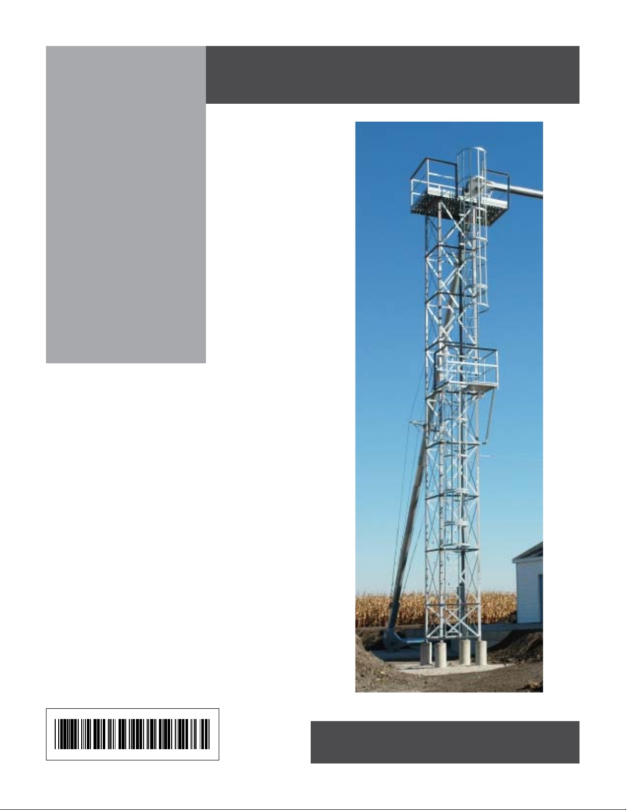
4 - Leg
Towers
4' x 4'
Chain Loop and 48"
Catwalk Designs
Installation Manual
PNEG-1413
DATE: 9-30-05
DATE: 10-18-04
PNEG-1413
Page 2

2
Pneg-1413 4-Leg Towers
Page 3

TABLE OF CONTENTS
Overview .....................................................................................................................................4
Tools ...........................................................................................................................................4
Safety .........................................................................................................................................5
Foundation..................................................................................................................................6
4-Leg Bottom Section ..............................................................................................................7
4-Leg Bottom Section - Dimensional Drawing ......................................................................8
Internal X-Braces..................................................................................................................9
4-Leg T ower Bottom Section Assembly .........................................................................10-11
4-Leg Tower 10' Mid Section..................................................................................................12
4-Leg Tower 10' Mid Section - Dimensional Drawing..........................................................13
4-Leg Tower 10' Mid Section Assembly ..............................................................................14
4-Leg Tower 5' Mid Section....................................................................................................15
4-Leg Tower 5' Mid Section - Dimensional Drawing............................................................16
4-Leg Tower 5' Mid Section Assembly ................................................................................17
4-Leg Tower Top Section.......................................................................................................18
4-Leg T ower Top Section - Dimensional Drawing................................................................19
4-Leg T ower Top Section Assembly ....................................................................................2 0
Connecting Two Tower Sections Together.......................................................................... 21
Optional Service Platform with Safety Cage ........................................................................22
Optional Service Platform with Safety Cage - Dimensional Drawing ............................. 23-24
Ladder Access Dimensional Drawing.................................................................................25
Optional Service Platform with Safety Cage Assembly.................................................. 26-31
4-Leg Tower Ladder Layouts ................................................................................................32
4-Leg T ower Ladder Attachment Detail Locations...............................................................33
Ladder Attachment to Bottom T ower Section ......................................................................34
Ladder Att achment to Between Two Safety Cage Sections.................................................35
Ladder Att achment to Offset Platform .................................................................................36
Offset Platform ........................................................................................................................37
Offset Platform Dimensional Drawing ........................................................................... 38-40
Offset Platform Assembly.............................................................................................. 41-45
10' Safety Cage Section ...........................................................................................................46
5' Safety Cage Section .............................................................................................................47
Warranty........................................................................................................... Inside Back Cover
Pneg-1413 4-Leg Towers
3
Page 4

OVERVIEW
Take time now and review the entire assembly manual. A few minutes now could save hours later during
assembly.
Check BOM against parts shipped and report any shortages now before assembly starts.
Foundation is critical for the structural integrity of the tower. Be sure to follow foundation design. A local
engineering firm should review site, soil conditions and foundation design before work is started. Local
codes may require the design stamped by a licensed engineer .
Depending on your work environment, these instructions may need to be altered to best fit your needs.
Assemble tower on a level horizontal surface. Block up column sections high enough to be able to place
horizontal angles under columns and attach with hardware provided. Note: V ertical “X” bracing must be
placed between column and H-Brace. Internal X-Bracing is used at every 5’ of vertical height. Bracing
attaches to the H-Braces.
Attach column splice plates to outside of columns using 1/2" hardware provided. Use splice on both outside
surfaces.
One style of assembly is to build 2 sides laying approximately 48" apart. Rotating sides up attach horizontal
bracing for proper spacing between sides. Keep sections small enough to handle easily. Slide section ends
together and splice together.
Once all sections have been assembled, align and string columns for straitness. Tighten all hardware, columns must be straight!!!
Layout parts for ladder package & service platform. With tower assembly complete & hardware tightened
proceed with attaching service platform & ladder sections. Refer to page 33 that shows general layout of
ladder, safety cage, & plat form. Use the layout that corresponds to the height of tower. Any tower over 30'
must use offset platform included with ladder package. Before starting ladder assembly give some consideration on how to raise tower and attachments to provide safe setting of tower. Some floor planks may need
to be left out until tower is stood in place.
Assemble service platform and attach to top of tower. Place opening of service platform on side of tower
that will have ladder. This will align ladder placement. Attach ladder from service platform towards bottom of
tower. Be sure and use the 10’ ladder access weldment in conjunction with the service platform. Follow the
general layout using the proper ladder section as you proceed. Offset platform is used only on towers over
30’ tall. Follow details for offset platform for proper attachment.
TOOLS
Drift Punches for 3/8" to 1/2" Bolts
3/4" Wrenches & Sockets
Ratchet & Impact Gun
9/16" Wrenches and Sockets
String
4
Pneg-1413 4-Leg Towers
Page 5
SAFETY
This equipment shall be installed in accordance with the current installation codes and applicable regulations which should be carefully followed in all cases. Authorities having jurisdiction should be consulted
before installations are made.
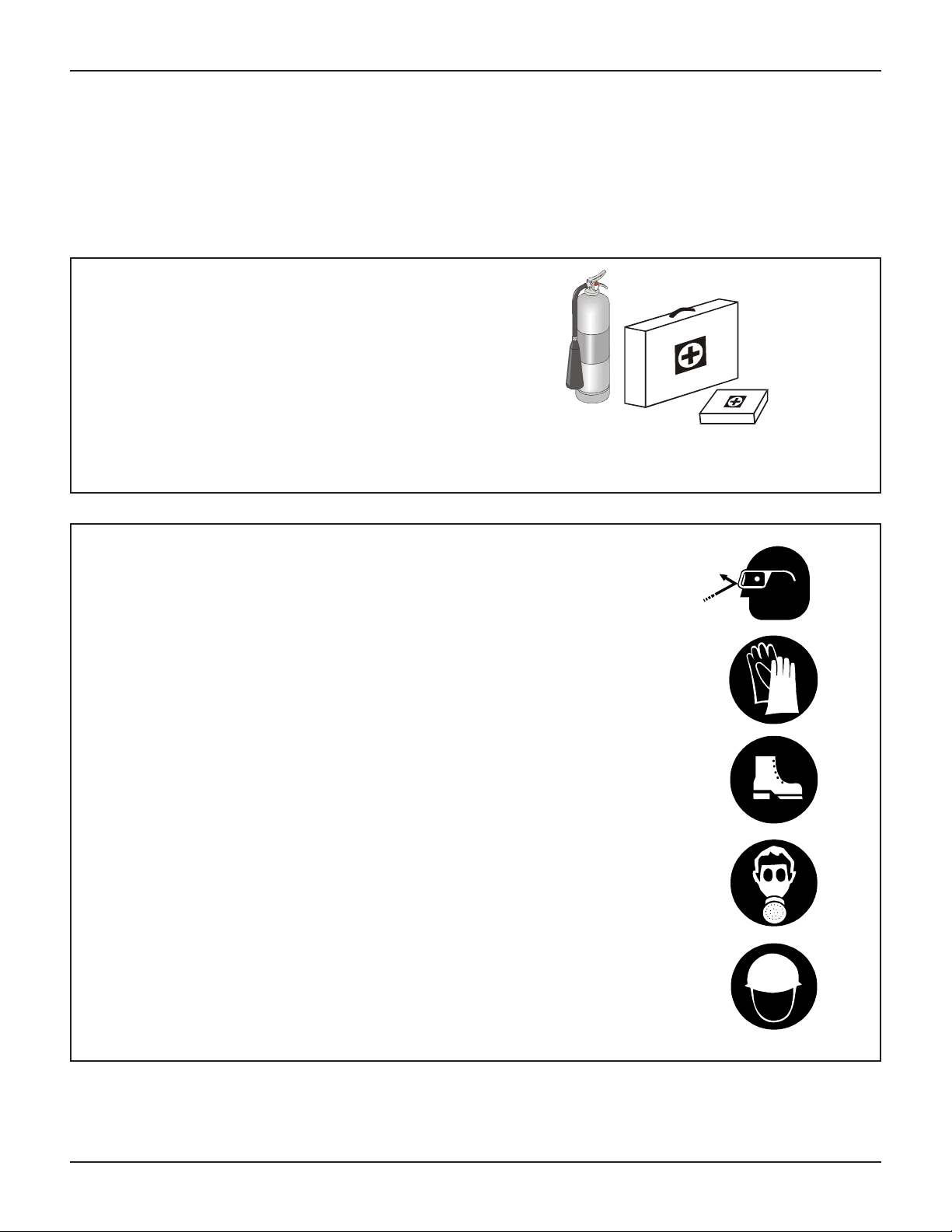
PREPARE FOR EMERGENCIES
Be prepared if fire starts.
Keep a first aid kit and fire extinguisher handy .
Keep emergency numbers for doctors, ambu-
lance service, hospital, and fire department near
your telephone.
WEAR PROTECTIVE CLOTHING
Keep Emergency Equipment
Quickly Accessible.
Wear close fitting clothing and safety equipment
appropriate to the job.
Safety glasses should be worn at all times to
protect eyes from debris.
Wear gloves to protect your hands from sharp
edges on plastic or steel parts.
A respirator may be needed to prevent breathing
potentially toxic fumes and dust.
Wear hard hat and steel toe boots to help
protect your head and toes from falling debris.
Remove all jewelry .
Tuck in any loose or dangling shoe strings.
Long hair should be tied up and back.
Eye Protection
Gloves
Steel Toe
Boots
Respirator
Hard Hat
Pneg-1413 4-Leg Towers
5
Page 6
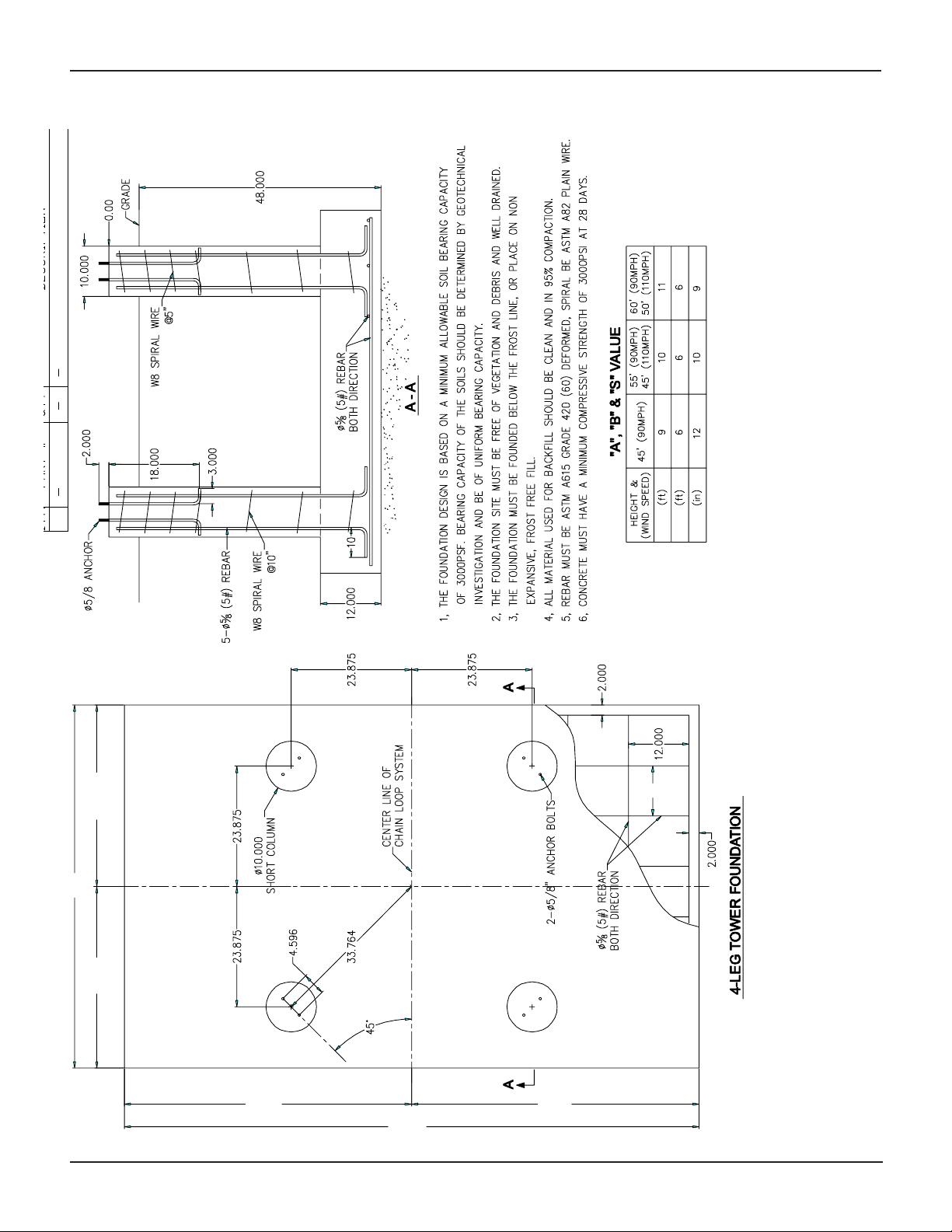
4-LEG TOWER FOUNDATION
A
B
S
Footing width and length chart
with rebar spacing based on
tower height and wind load.
B\2
B
B\2
A\2
A
6
A\2
S
Foundation design is based on support of tower
and tower turn over. Failure to follow foundation
Pneg-1413 4-Leg Towers
recommendation voids tower warranty.
Page 7
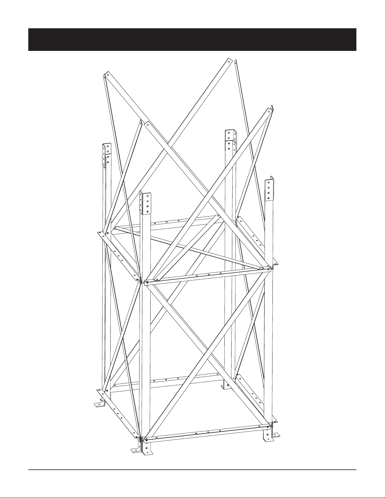
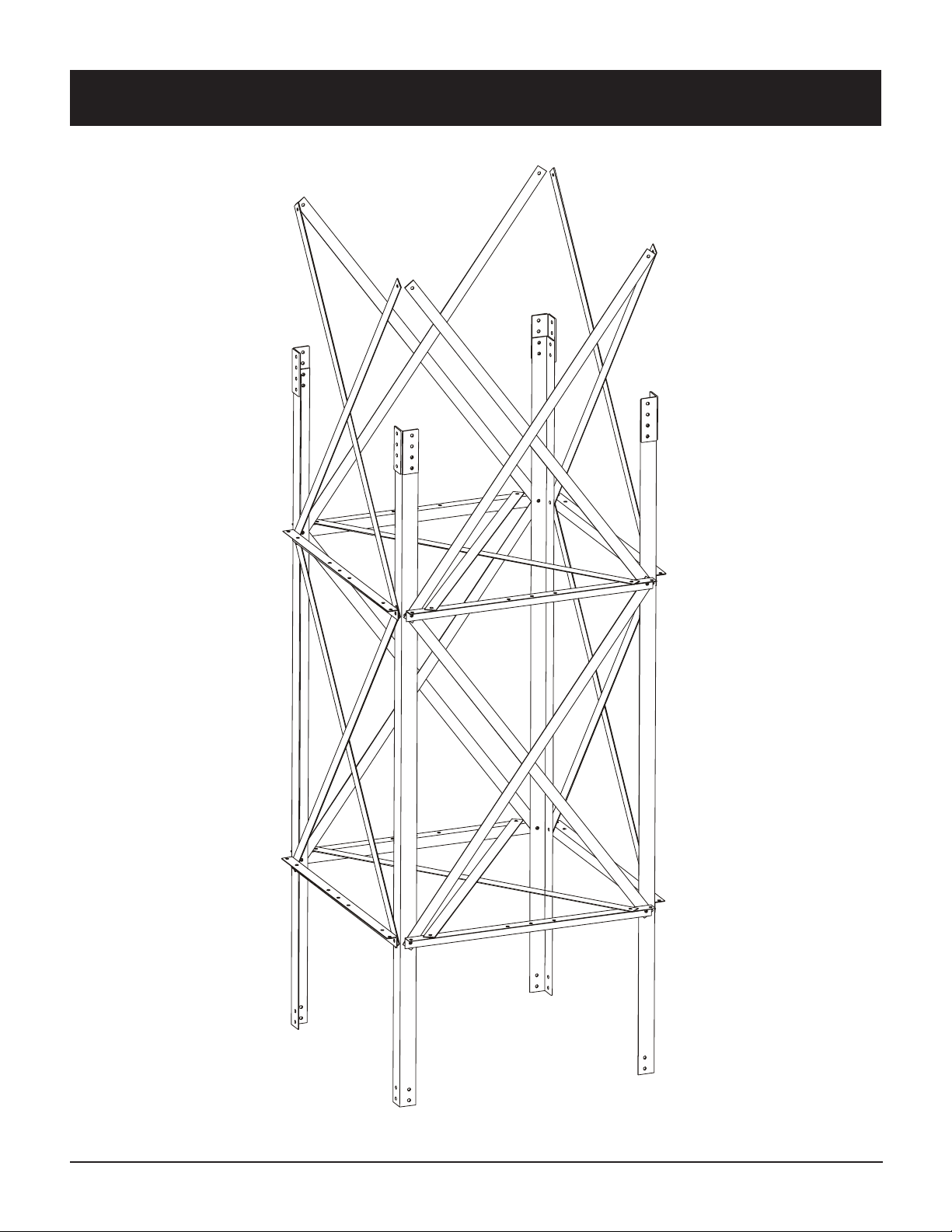
4-LEG TOWER BOTTOM SECTION
Pneg-1413 4-Leg Towers
7
Page 8
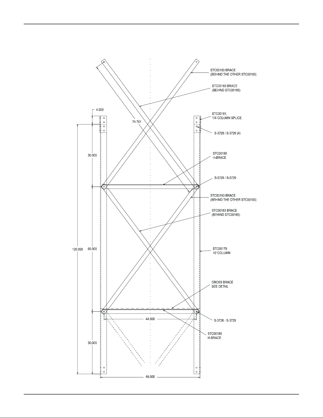
4-LEG TOWER BOTTOM SECTION
DIMENSIONAL DRAWING
OTHER SIDES
BOTTOM SECTION-A
8
Pneg-1413 4-Leg Towers
Page 9
INTERNAL X-BRACES
Pneg-1413 4-Leg Towers
NOTE: Ladder Side of Tower.
(Internal X-Braces must NOT attach to horizontal
brace on side that ladder attaches too.)
9
Page 10
4-LEG TOWER BOTTOM SECTION ASSEMBLY
SIDE 1 & SIDE 2 ASSEMBLY
1. Attach (2) Tower Anchor Clips (STC00177) to
bottom holes in each Bottom Column
(STC00366) using 1/2" hardware provided
(S-3729 & S-3728). (See Fig. 1)
2. Attach Vertical X-Braces (STC00183) to the
bottom columns (STC00366) as shown in Fig. 1
using 1/2" hardware provided.
STC00181
(Column Splice Plates)
STC00183
(Vertical X-Braces)
3. Attach the column splice plates (STC00181) to
the tops of the columns (STC00366), using (2)
1/2" x 1-1/2" HHCS bolts (S-3729) and nuts
(S-3728) for each plate. (See Fig. 1)
4. Repeat steps 1-3 for the opposite side, so you
have two identical sections.
10
STC00185
(H-Braces)
S-3728
(1/2" x 1-1/2"
HHCS Bolts)
STC00336
(Bottom
Columns)
S-3729
(1/2" Hex Nuts)
STC00177
(Anchor Clips)
FIG. 1
Pneg-1413 4-Leg Towers
Page 11
4-LEG TOWER BOTTOM SECTION
SIDE 3 & SIDE 4 ASSEMBLY
1. Connect the first two sections together by
attaching the Vertical X-Braces (STC00183) &
H-Braces (STC00185) as shown in Fig. 2, using
the 1/2" hardware provided.
STC00226
(Internal X-Braces)
2. Attach the Internal X-Braces (STC00226) to the
H-Braces (STC00185) as shown in Fig. 2, using
the 1/2" hardware provided (S-7534 & S-3729).
FIG. 2
S-7534
(1/2" x 1-1/4"
HHCS Bolts)
S-3729
(1/2" Hex Nuts)
STC00181
(Column Splice Plates)
STC00336
(Bottom
Columns)
STC00177
(Anchor Clips)
STC00183
(Vertical X-Braces)
S-3729
(1/2" Hex Nuts)
STC00185
(H-Braces)
S-3728
(1/2" x 1-1/2"
HHCS Bolts)
Pneg-1413 4-Leg Towers
11
Page 12
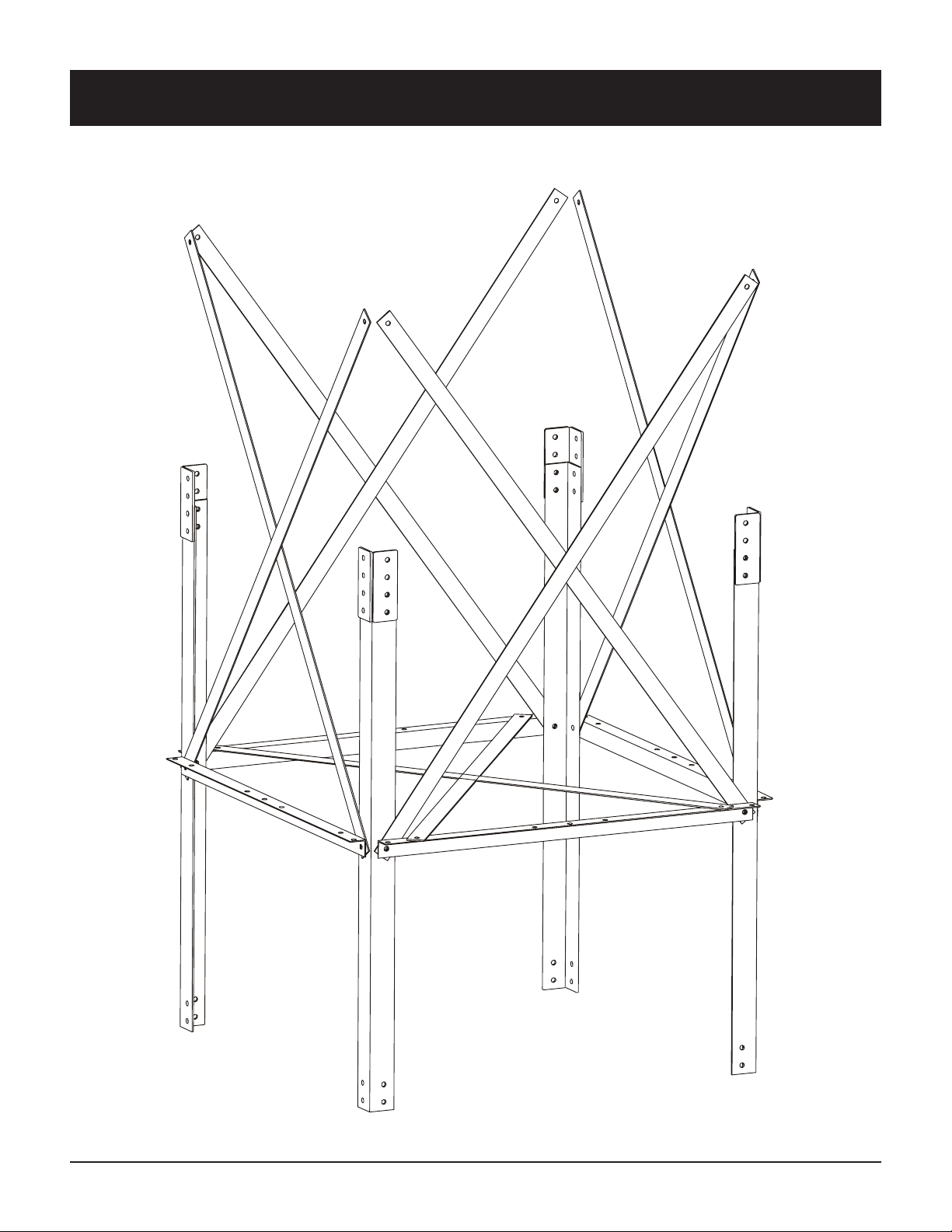
4-LEG TOWER 10' MID SECTION
12
Pneg-1413 4-Leg Towers
Page 13
4-LEG TOWER 10' MID SECTION
DIMENSIONAL DRAWING
Pneg-1413 4-Leg Towers
10 FOOT SECTION
13
Page 14
4-LEG TOWER 10' MID SECTION ASSEMBLE
SIDE 1 & SIDE 2 ASSEMBLY
2. Attach Vertical X-Braces (STC00183) and the
H-Braces (STC00185) to the 10' Columns
(STC00179) as shown in Fig. 3 using
1/2" hardware provided.
3. Attach the column splice plates (STC00181) to
the tops of the 10' Columns (STC00179), using
(2) 1/2" x 1-1/2" HHCS bolts (S-3729) and nuts
(S-3728) for each plate. (See Fig. 3)
4. Repeat steps 1-3 for the opposite side, so you
have two identical sections.
S-3729
(1/2" Hex
Nuts)
SIDE 3 & SIDE 4 ASSEMBLY
1. Connect the first two sections together by
attaching the V ertical X-Braces (STC00183) and
H-Braces (STC00185) as shown in Fig. 3, using
the 1/2" hardware provided.
2. Attach the Internal X-Braces (STC00226) to the
H-Braces (STC00185) as shown in Fig. 3, using
the 1/2" hardware provided (S-7534 & S-3729).
FIG. 3
STC00181
(Column Splice Plates)
S-3728
(1/2" x 1-1/2" HHCS Bolts)
S-7534
(1/2" x 1-1/4"
HHCS Bolts)
STC00226
(Internal X-Braces)
14
S-3729
(1/2" Hex Nuts)
STC00179
(10' Columns)
S-3729
(1/2" Hex Nuts)
STC00183
(Vertical X-Braces)
STC00185
(H-Braces)
S-3728
(1/2" x 1-1/2" HHCS Bolts)
Pneg-1413 4-Leg Towers
Page 15
4-LEG TOWER 5' MID SECTION
Pneg-1413 4-Leg Towers
15
Page 16

4-LEG TOWER 5' MID SECTION
DIMENSIONAL DRAWING
16
Pneg-1413 4-Leg Towers
Page 17

4-LEG TOWER 5' MID SECTION ASSEMBLY
SIDE 1 & SIDE 2 ASSEMBLY
1. Attach Vertical X-Braces (STC00183) to the 5'
Columns (STC00337) as shown in Fig. 4 using
1/2" hardware provided.
2. Attach the column splice plates (STC00181) to
the tops of the 5' Columns (STC00337), using
(2) 1/2" x 1-1/2" HHCS bolts (S-3729) and nuts
(S-3728) for each plate. (See Fig. 4)
3. Repeat steps 1-2 for the opposite side, so you
have two identical sections.
SIDE 3 & SIDE 4 ASSEMBLY
1. Connect the first two sections together by
attaching the Vertical X-Braces (STC00183) and
H-Braces (STC00185) as shown in Fig. 4, using
the 1/2" hardware provided.
2. Attach the Internal X-Braces (STC00226) to the
H-Braces (STC00185) as shown in Fig. 4, using
the 1/2" hardware provided (S-7534 & S-3729).
FIG. 4
STC00181
(Column Splice Plates)
STC00226
(Internal XBraces)
STC00337
(5' Columns)
S-3729
(1/2" Hex
Nuts)
S-7534
(1/2" x 1-1/4"
HHCS Bolts)
S-3728
(1/2" x 1-1/2"
HHCS Bolts)
STC00183
(Vertical X-Braces)
S-3728
(1/2" x 1-1/2"
HHCS Bolts)
STC00185
(H-Braces)
S-3729
(1/2" Hex Nuts)
Pneg-1413 4-Leg Towers
17
Page 18

4-LEG TOWER TOP SECTION
18
Pneg-1413 4-Leg Towers
Page 19

4-LEG TOWER TOP SECTION
DIMENSIONAL DRAWING
Pneg-1413 4-Leg Towers
TOP SECTION
19
Page 20

4-LEG TOWER TOP SECTION ASSEMBLY
SIDE 1 & SIDE 2 ASSEMBLY
1. Attach Vertical X-Braces (STC00183) to the Top
Columns (STC00180) as shown in Fig. 5 using
1/2" hardware provided.
2. Attach the column splice plates (STC00181) to
the tops of the Top Columns (STC00180), using
(2) 1/2" x 1-1/2" HHCS bolts (S-3729) and nuts
(S-3728) for each plate. (See Fig. 5)
3. Repeat steps 1-2 for the opposite side, so you
have two identical sections.
S-7534
(1/2" x 1-1/4"
HHCS Bolts)
S-3729
(1/2" Hex
Nuts)
SIDE 3 & SIDE 4 ASSEMBLY
1. Connect the first two sections together by
attaching the V ertical X-Braces (STC00183) and
H-Braces (STC00185) as shown in Fig. 5, using
the 1/2" hardware provided.
2. Attach the Internal X-Braces (STC00226) to the
H-Braces (STC00185) as shown in Fig. 5, using
the 1/2" hardware provided (S-7534 & S-3729).
FIG. 5
20
STC00180
(T op Columns)
STC00183
(Vertical X-Braces)
STC00226
(Internal XBraces)
STC00185
(H-Braces)
S-3728
(1/2" x 1-1/2"
HHCS Bolts)
S-3729
(1/2" Hex Nuts)
Pneg-1413 4-Leg Towers
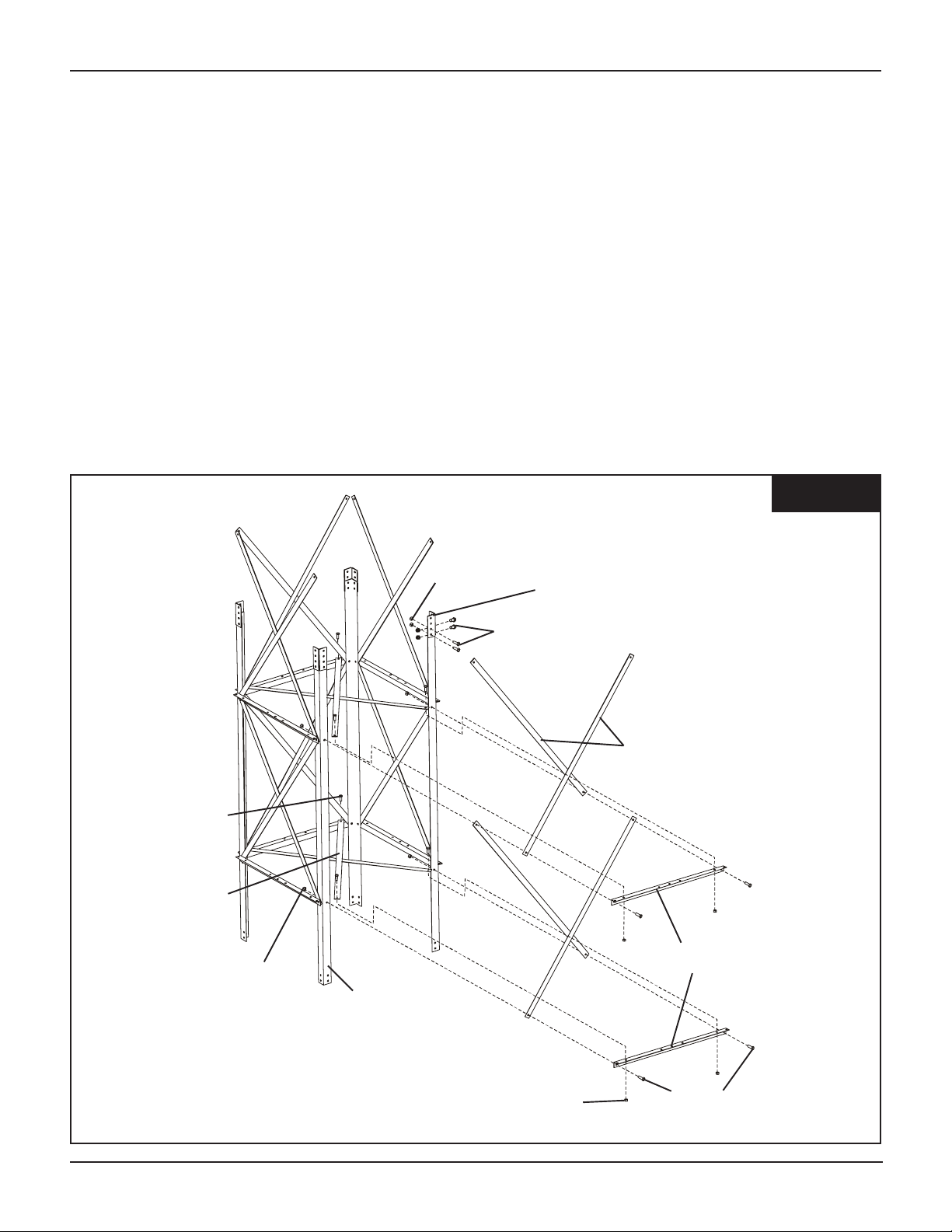
Page 21

ATTACHING TOWER
SECTIONS TOGETHER
1. Line up Top Section Columns with Column
Splice Plates (STC00181) of bottom section.
2. Attach together using (2) 1/2" x 1-1/2" HHCS
bolts & nuts per splice plate.
3. Attach Vertical X-Braces (STC00183) and HBraces (STC00185) to columns as shown
using 1/2" x 1-1/2" HHCS bolts & nuts.
NOTE: H-Braces (STC00185) should be
installed on top of the V ertical X-Braces
(STC00183). Some H-Braces may need to be
removed to install the V ertical X-Braces under
the H-Braces.
S-3728
(1/2" x 1-1/2"
HHCS Bolts)
S-3729
(1/2" Hex
Nuts)
STC00181
(Column Splice Plates)
S-3728
(1/2" x 1-1/2"
HHCS Bolts)
STC00183
(Vertical X-Braces)
STC00185
(H-Braces)
Pneg-1413 4-Leg Towers
21
Page 22

OPTIONAL SERVICE PLATFORM
WITH SAFETY CAGE
22
Pneg-1413 4-Leg Towers
Page 23

SERVICE PLATFORM DIMENSIONAL DRAWINGS
SIDE VIEW
Pneg-1413 4-Leg Towers
PLAN VIEW
SIDE VIEW
23
Page 24

SERVICE PLATFORM DIMENSIONAL DRAWINGS
PLAN VIEW
BACK SIDE VIEW
LADDER ACCESS SIDE VIEW
LEFT/RIGHT SIDE VIEW
24
Pneg-1413 4-Leg Towers
Page 25

A
A
A
LADDER ACCESS DIMENSIONAL DRAWINGS
END VIEW
L
DDER
CCESS
SSEMBLY
TOP VIEW
SIDE VIEW
Pneg-1413 4-Leg Towers
25
Page 26

OPTIONAL SERVICE
PLATFORM WITH
SAFETY CAGE
ASSEMBLY
Assembling the service platform first and
placing the opening on the side of the tower
that will have ladder, will align ladder placement. Att ach ladder to service plat form and
install ladders starting from the top and working
down towards bottom of tower. Be sure and
use the 10’ ladder access weldment in conjunction with the service platform. Follow the
general layout from page 33 using the proper
ladder section as you proceed.
1. Attach Service Platform Short Frames
(STC00192) to the 94-1/2" Top Columns
(STC00180) of the top tower section using
(4) 3/8" x 1" HHCS bolts & nuts as shown
in Fig SP1.
S-8671
(3/8" x 1" HHCS Bolts)
STC00192
(Service
Platform
Short
Frame)
S-8671
(3/8" x 1" HHCS Bolts)
S-456
(3/8" Hex
Nuts)
S-456
(3/8" Hex Nuts)
STC00192
(Service Platform
Short Frame)
STC00180
(94-1/2" Top
Column)
STC00185
(“H” Brace)
FIG. SP1
STC00193
(Service
Platform Clip)
2. Attach (4) Service Platform Clips
(STC00193) to the Service Platform Short
Frames (STC00192) using (2) 3/8" x 1"
HHCS bolts & nuts for each clip as shown
in Fig SP2.
3. Attach (2) Service
Platform Long Frames
(STC00191) to the
Service Platform Clips
(STC00193) using (2)
3/8" x 1" HHCS bolts &
nuts for each clip as
shown in Fig. SP3.
S-8671
(3/8" x 1"
HHCS Bolts)
FIG. SP2
STC00191
(Service Platform
Long Frame)
STC00193
(Service
Platform Clip)
S-456
(3/8" Hex
Nuts)
26
FIG. SP3
Pneg-1413 4-Leg Towers
Page 27

OPTIONAL SERVICE
PLATFORM WITH
SAFETY CAGE
ASSEMBLY (CONT.)
4. Attach (4) Service Platform Clips
(STC00193) to the ends of the Service
Platform Long Frames (STC00191) using
(2) 3/8" x 1" HHCS bolts & nuts for each
clip as shown in Fig. SP4.
5. Attach Service Platform Short Frame
(STC00192) to the Service Platform Clips
(STC00193) on the ends of the Service
Platform Long Frames (STC00191) using
(2) 3/8" x 1" HHCS bolts & nuts for each
clip as shown in Fig. SP5.
NOTE: Field cope flanges of platform
planks near STC00191 (Service Platform
Long Frame), to avoid handrail post clips &
bolts.
STC00193
(Service
Platform Clip)
STC00191
(Service Platform
Long Frame)
STC00193
(Service
Platform Clips)
STC00191
(Service Platform
Long Frame)
S-8671
(3/8" x 1"
HHCS Bolts)
S-456
(3/8" Hex
Nuts)
FIG. SP4
STC00192
(Service Platform
Short Frame)
S-456
(3/8" Hex
Nuts)
S-8671
(3/8" x 1"
HHCS Bolts)
6. Attach (8) Service Platform Clips
(STC00193) to the Service Platform Long
Frame (STC00191) using (8) 3/8" x 1"
HHCS bolts & nuts as shown in Fig. SP6.
7. Attach 9' x 12' Platform Planks
(STC00194) to the Service Platform Short
Frames (STC00192) using (4) 3/8" x 1"
HHCS bolts for each plank as shown in
Fig. SP6.
FIG. SP6
STC00192
(Service Platform
Short Frame)
STC00191
(Service
Platform Long
Frame)
STC00193
(Service
Platform Clips)
FIG. SP5
STC00194
(9' x 12" Platform Planks)
S-8671
(3/8" x 1"
HHCS Bolts)
S-456
(3/8" Hex
Nuts)
Pneg-1413 4-Leg Towers
27
Page 28

OPTIONAL SERVICE
PLATFORM WITH
SAFETY CAGE
ASSEMBLY (CONT.)
8. Attach (8) Handrail Posts
(STC00198) to the Service Platform
Long Frames (STC00191) using (8)
3/8" x 1" HHCS bolts & nuts as
shown in Fig. SP7.
9. Attach (2) 5' Top Handrails
(STC00201), (2) 5' Mid Bars
(STC00202), and (2) 5' Kicker
Plates (STC00203) to the Handrail
Posts (STC00198) using (16) 3/8" x
1" HHCS bolts & nuts as shown in
Fig. SP8.
S-8671
(3/8" x 1"
HHCS Bolts)
STC00191
(Service Platform
Long Frame)
STC00201
(5' Top Handrail)
STC00198
(Handrail Post)
STC00202
(5' Mid Bar)
FIG. SP7
S-456
(3/8" Hex Nuts)
(Behind Planks)
FIG. SP8
STC00198
(Handrail Post)
S-456
(3/8" Hex
Nuts)
28
STC00203
(5' Kicker Plate)
S-8671
(3/8" x 1"
HHCS Bolts)
Pneg-1413 4-Leg Towers
Page 29

OPTIONAL SERVICE PLATFORM WITH
SAFETY CAGE ASSEMBLY (CONT.)
10. Attach 9' Top Handrail
(STC00195), 9' Mid Bar
(STC00196), and 9' Kicker
Plate (STC00197) to the
Handrail Posts (STC00198)
using (16) 3/8" x 1" HHCS
bolts & nuts as shown in Fig.
SP9.
1 1. Attach 38-1/4" Top Handrail
(STC00204), 38-1/4" Mid Bar
(STC00205), and 38-1/4"
Kicker Plate (STC00206) to
the Handrail Posts
(STC00198) using (16) 3/8" x
1" HHCS bolts & nuts as
shown in Fig. SP10.
STC00198
(Handrail
Posts)
STC00196
(9' Mid Bar)
STC00197
(9' Kicker
Plate)
STC00195
(9' Top Handrail)
S-456
(3/8" Hex
Nuts)
S-8671
(3/8" x 1"
HHCS Bolts)
FIG. SP9
STC00206
(38-1/4"
Kicker Plate)
STC00198
(Handrail
Posts)
S-8671
(3/8" x 1"
HHCS Bolts)
STC00204
(38-1/4" Top
Handrail)
STC00205
(38-1/4"
Mid Bar)
S-456
(3/8" Hex
Nuts)
FIG. SP10
Pneg-1413 4-Leg Towers
29
Page 30

OPTIONAL SERVICE
PLATFORM WITH
SAFETY CAGE
ASSEMBLY (CONT.)
12. Attach (4) Ladder Handrail T ies
(STC00200) to the Handrail Posts
(STC00198) using (4) 3/8" x 1"
HHCS bolts & nuts as shown in
Fig SP1 1.
13. Attach 10' Ladder Access Assembly (STCA0073) to the Ladder
Handrail Ties (STC00200) using
(4) 1/2" x 1-1/4" HHCS bolts &
nuts as shown in Fig SP12.
S-456
(3/8" Hex
Nuts)
STC00200
(Ladder Handrail Tie)
STC00198
(Handrail
Posts)
S-8671
(3/8" x 1"
HHCS Bolts)
S-7534
(1/2" x 1-1/4" HHCS Bolts)
STC00200
(Ladder
Handrail Ties)
FIG. SP11
S-3729
(1/2" Hex Nuts)
30
STCA0073
(10' Ladder
Access
Assembly)
FIG. SP12
Pneg-1413 4-Leg Towers
Page 31

OPTIONAL SERVICE
PLATFORM WITH
SAFETY CAGE
ASSEMBLY (CONT.)
14. Attach (2) Safety Cage Hoops
(STC00213) and (2) 10' Ladder Cage
Hoops (STC00212) to the 10' Ladder
Access Assembly (STCA0073) using
(2) 1/2" x 1-1/4" HHCS bolts & nuts
for each hoop as shown in Fig SP13.
STC00213
(Safety
Cage Hoop)
STCA0073
(10' Ladder
Access
Assembly)
15. Attach 10' Vertical Bar (10FOOT-V)
to the Cage Hoops (STC00213 &
STC00212) using (4) 1/2" x 1-1/4"
HHCS bolts & nuts for each vertical
bar as shown in Fig. SP14.
STC00212
(10'
Access
Ladder
Cage
Hoop)
NOTE: Bolt
heads go to
inside of
Safety Cage.
10FOOT-V
(10' Vertical
Bar)
S-3729
(1/2" Hex Nuts)
S-7534
(1/2" x 1-1/4"
HHCS Bolts)
FIG. SP13
Pneg-1413 4-Leg Towers
S-3729
(1/2" Hex
Nuts)
S-7534
(1/2" x 1-1/4"
HHCS Bolts)
FIG. SP14
31
Page 32

4-LEG TOWER LADDER LAYOUTS
Diagram represents the different height ladder
packages for the 4' square towers. An access ladder
is used in conjunction with service platform. Layout
ladder from top down. The length of ladder is shown
above for proper layout. Use the corresponding
safety cage with ladder sections. 14' ladder takes 10’
safety cage used just below offset rest platform.
32
Pneg-1413 4-Leg Towers
Page 33

LADDER ATTACHMENT DETAIL LOCATIONS
STC00186
Horizontal Brace
Location
(On ladder
Packages with
Offset Platform
Only .)
UPPER LADDER SECTION
Pneg-1413 4-Leg Towers
SIDE VIEW OF
LOWER LADDER SECTION
33
Page 34

LADDER ATTACHMENT TO BOTTOM
TO WER SECTION
1. Attach ladder stands (STC00207) to the bottom
H-Brace (STC00185) using 1/2" x 1-1/4" HHCS
bolts & nuts.
VIEW OF DETAIL #4 FROM PAGE 34.
2. Attach the Ladder S plice Plates #2 (STC00209)
to the Ladder and Ladder Stands (STC00207)
using (3) 1/2" x 1-1/4" HHCS bolts & nuts for
each splice plate. (See Fig. 7)
STC00207
(Ladder Stand)
STC00185
(H-Brace)
S-7534
(1/2" x 1-1/4"
HHCS Bolts)
S-3729
(1/2" Hex Nuts)
STC00209
(Ladder Splice
Plate #2)
Ladder
S-7534
(1/2" x 1-1/4"
HHCS Bolts)
FIG. 7
34
Pneg-1413 4-Leg Towers
Page 35

LADDER ATTACHMENT BETWEEN TWO
SAFETY CAGE SECTIONS
VIEW OF DETAIL #1 FROM PAGE 34.
STC00207
(Ladder Stand)
STC00210
(Ladder Splice
Plate #1)
S-7534
(1/2" x 1-1/4"
HHCS Bolts)
FIG. 8
STC00185
(H-Brace)
S-3729
(1/2" Hex Nuts)
S-7534
(1/2" x 1-1/4"
HHCS Bolts)
STC00213
(Safety Cage Hoop)
27HOOP
(2' - 27" Hoop)
1. Ladder Stands (STC00207) to H-Brace
(STC00185) using 1/2" x 1-1/4" HHCS
bolts & nuts. (See Fig. 8)
2. Attach Ladder S plice Plates #1
(STC00210) to Ladders and Ladder
Stands (STC00207) using (3) 1/2" x 1-1/4"
HHCS bolts & nuts for each splice plate.
(See Fig. 8)
3. Attach the Safety Cage Hoop (STC00213)
and the 2'-27" Hoop (27HOOP) to the
splice plate using (2) 1/2" x 1-1/4" HHCS
bolts & nuts for each hoop. (See Fig. 9)
4. Attach the vertical bars to the hoops using
the 1/2" hardware provided as shown in
Fig. 10.
S-3729
(1/2" Hex Nuts)
FIG. 9
S-7534
(1/2" x 1-1/4"
HHCS Bolts)
S-3729
(1/2"
Hex
Nuts)
10Foot-V
(10' Vertical
Bar)
FIG. 10
Pneg-1413 4-Leg Towers
35
Page 36

LADDER ATTACHMENT TO OFFSET PLATFORM
NOTE: ALL connections on
this page use 1/2" x 1-1/4"
HHCS bolts (S-7534) and
1/2" hex nuts (S-3729).
ALL bolt heads go to inside of
the ladders.
1. Attach (4) Ladder St ands
(STC00207) to the HBraces (STC00185)
using (4) bolts & nuts.
2. Attach Ladder S plice
Plate #1 (STC00208) to
the Ladder St ands
(STC00207) and the 14'
Ladder using (6) bolts &
nuts. (See Fig. 11)
3. Attach Ladder S plice
Plates #2 (STC00209) to
the Ladder St ands
(STC00207) and the 10'
Ladder using (6) bolts &
nuts. (See Fig. 11)
FIG. 11
STC00209
(Ladder Splice
Plate #2)
VIEW OF DETAIL #2 FROM PAGE 34.
NOTE: Some
parts removed
for clarity .
36
STC00208
(Ladder Splice
Plate #1)
S-3729
(1/2" Hex Nuts)
STC00207
(Ladder Stand)
S-7534
(1/2" x 1-1/4" HHCS Bolts)
Pneg-1413 4-Leg Towers
Page 37

OFFSET PLATFORM
Pneg-1413 4-Leg Towers
37
Page 38

OFFSET PLATFORM DIMENSIONAL DRAWINGS
38
Pneg-1413 4-Leg Towers
Page 39

OFFSET PLATFORM DIMENSIONAL DRAWINGS
Pneg-1413 4-Leg Towers
S-6497
39
Page 40

OFFSET PLATFORM DIMENSIONAL DRAWINGS
40
Pneg-1413 4-Leg Towers
Page 41

OFFSET PLATFORM
ASSEMBLY
S-7534
(1/2" x 1-1/4"
HHCS Bolts)
FIG. OP1
1. Follow the ladder layouts on page 22 for your
ladder package. S tarting from the top of tower
and working down, should give you the proper
location for the Rest Platform Long Frame
(STC00188) and the Rest Platform "H" Brace
(STC00186).
2. Attach the Rest Platform Long Frame
(STC00188) to the H-Brace (STC00185).
Then replace the H-Brace (STC00185) that is
below the offset platform with the Rest Platform “H”-Brace (STC00186). Use (4) 1/2" x
1-1/4" bolts & nuts (See Fig. OP1)
3. Attach Handrail Posts (STC00198) to the
Rest Platform Long Frame (STC00188)
using (2) 3/8" x 1" bolts & nuts. (See Fig
OP2)
4. Attach the 5' Top Handrail (STC00201) and
the 5' Mid Bar (STC00202) to the Handrail
Posts (STC00198) using (4) 3/8" x 1" HHCS
bolts & nuts. (See Fig. OP3)
STC00188
(Rest Platform
Long Frame)
S-3729
(1/2" Hex
Nuts)
STC00185
(H-Brace
Replace with
STC00186)
STC00186
(“H” Brace Rest
Platform)
STC00198
(Handrail Posts)
S-456
(3/8" Hex
Nuts)
S-7534
(1/2" x 1-1/4"
HHCS Bolts)
S-8671
(3/8" x 1"
HHCS Bolts)
STC00188
(Rest Platform
Long Frame)
S-8671
(3/8" x 1"
HHCS Bolts)
STC00198
(Handrail
Posts)
FIG. OP2
S-456
(3/8" Hex
Nuts)
STC00201
(5' Top Handrail)
STC00202
(5' Mid Bar)
FIG. OP3
Pneg-1413 4-Leg Towers
41
Page 42

OFFSET PLATFORM
ASSEMBLY (CONT.)
5. Attach (4) Ladder S t and (STC00207) to the HBrace (STC00185) and Rest Platform Long
Frame (STC00188) using (4) 1/2" x 1-1/4"
HHCS bolts & nuts. (See Fig. OP4)
6. Attach (2) Ladder S plice Plate #1 (STC00208)
to the Ladder Stands (STC00207) and the 14'
Ladder using (6) 1/2" x 1-1/4" bolts & nuts.
(See Fig. OP5)
3. Attach (2) Ladder S plice Plates #2
(STC00209) to the Ladder Stands
(STC00207) and the 10' Ladder using (6) 1/2"
x 1-1/4" bolts & nuts. (See Fig. OP5)
S-3729
(1/2"
Hex
Nuts)
FIG. OP4
S-7534
(1/2" x 1-1/4"
HHCS Bolts)
STC00207
(Ladder Stand)
STC00185
(H-Braces)
10' Ladder
STC00188
(Rest Platform
Long Frame)
FIG. OP5
14' Ladder
42
S-3729
(1/2"
Hex
Nuts)
STC00209
(Ladder Splice
Plate #2)
S-7534
(1/2" x 1-1/4"
HHCS Bolts)
Pneg-1413 4-Leg Towers
STC00208
(Ladder Splice
Plate #1)
Page 43

OFFSET PLATFORM ASSEMBLY (CONT.)
7. Attach the (3) Rest Platform
Short Frames (STC00189 &
STC00189-A) to the Rest
Platform Long Frame
(STC00188) and the Handrail Post (STC00198) as
shown in Fig. OP6. Use
1/2" x 1-1/4" HHCS Bolts
and nuts.
8. Attach the Handrail Post
Clips (STC00199) to the
Rest Platform H-Brace
(STC00186) using (2) 1/2" x
1-1/4" HHCS bolts & nuts.
9. Attach the Rest Platform
Kneebraces (STC00187) to
the Rest Platform Short
Frames (STC00189) using
(2) 1/2" x 1-1/4" HHCS bolts
& nuts as shown in Fig. OP7
STC00198
(Handrail Post)
S-7534
(1/2" x 1-1/4"
HHCS Bolts)
S-3729
(1/2" Hex
Nuts)
STC00189-A
(Rest Platform
Short Frame)
STC00188
(Rest Platform
Long Frame)
FIG. OP6
STC00189
(Rest Platform
Short Frame)
FIG. OP7
10. Attach the Rest Platform
Kneebraces (STC00187) to
the Handrail Post Clips
(STC00199) using (2) 1/2" x
1-1/4" HHCS bolts & nuts.
(See Fig. OP7)
STC00189
(Rest Platform
Short Frame)
STC00187
(Rest Platform
Kneebrace)
S-3729
(1/2" Hex
Nuts)
S-7534
(1/2" x 1-1/4"
HHCS Bolts)
STC00186
(Rest Platform
H-Brace)
STC00199
(Handrail
Post Clip)
Pneg-1413 4-Leg Towers
43
Page 44

OFFSET PLATFORM
ASSEMBLY (CONT.)
FIG. OP8
STC00189-A
(Rest Platform
Short Frame)
11. Attach the Rest Platform Long Frame
(STC00188) to the (3) Rest Platform Short
Frames (STC00189 & STC00189-A) using
(3) 1/2" x 1-1/4" HHCS bolts & nuts as shown
in Fig OP8.
12. Attach (2) Handrail Posts (STC00198) to
Rest Platform Short Frame (STC00189) and
Rest Platform Long Frame (STC00188) using
3/8" x 1" HHCS bolts & nuts as shown in Fig.
OP9.
STC00189
(Rest Platform
Short Frame)
S-7534
(1/2" x 1-1/4"
HHCS Bolts)
S-3729
(1/2" Hex
Nuts)
STC00188
(Rest Platform
Long Frame)
STC00198
(Handrail
Posts)
STC00189
(Rest
Platform
Short
Frame)
S-456
(3/8" Hex
Nuts)
S-8671
(3/8" x 1"
HHCS Bolts)
STC00188
(Rest Platform
Long Frame)
FIG. OP9
44
Pneg-1413 4-Leg Towers
Page 45

OFFSET PLATFORM
ASSEMBLY (CONT.)
STC00198
(Handrail
Posts)
FIG. OP10
STC00204
(38-1/2" Top
Handrail)
13. Attach (2) 38-1/2" Top Handrails (STC00204),
(2) 38-1/2" Mid Bars (STC00205), and (1)
38-1/2" Kicker Plate (STC00206) to the
Handrail Posts (STC00198) using (12) 3/8" x
1" HHCS bolts and nuts as shown in Fig.
OP10.
14. Attach the 5' Top Handrail (STC00201) and 5'
Mid Bar (STC00202) to the Handrail Posts
(STC00198) using (4) 3/8" x 1" HHCS bolts
and nuts as shown in Fig. OP11.
15. Attach the Rest Platform Plank (STC00190)
to the Rest Platform Short Frames
(STC00189 & STC00189-A) using
(8) 1/4" x 3/4" self drilling screws (S-6497).
Make sure to offset screws from any existing
holes. (See Fig. OP12)
S-456
(3/8" Hex
Nuts)
STC00201
(5' Top
Handrail)
STC00205
(38-1/2" Top
Handrail)
STC00206
(38-1/2" Top
Handrail)
S-8671
(3/8" x 1"
HHCS Bolts)
FIG. OP11
S-8671
(3/8" x 1"
HHCS Bolts)
S-456
(3/8" Hex
Nuts)
STC00198
(Handrail
Post)
STC00189
(Rest Platform
Short Frame)
STC00202
(5' Mid Bar)
FIG. OP12
S-6497
(1/4" x 3/4"
Self Drilling
Screws)
STC00190
(Rest Platform
Plank)
STC00189-A
(Rest Platform
Short Frame)
Pneg-1413 4-Leg Towers
45
Page 46

10' SAFETY CAGE SECTION
27HOOP
(2' - 27" Hoop)
10FOOT-V
(10' Vertical Bars)
S-7534
(1/2" x 1-1/4"
HHCS Bolts)
46
S-3729
(1/2" Hex Nuts)
Pneg-1413 4-Leg Towers
Page 47

27HOOP
(2' - 27" Hoop)
5' SAFETY CAGE SECTION
5FOOT-V
(5' Vertical Bars)
S-7534
(1/2" x 1-1/4"
HHCS Bolts)
S-3729
(1/2" Hex Nuts)
Pneg-1413 4-Leg Towers
47
Page 48

NOTES
48
Pneg-1413 4-Leg Towers
Page 49

The GSI Group, Inc. Warranty
THE GSI GROUP, INC. (“GSI”) WARRANTS ALL PRODUCTS WHICH IT MANUFACTURES TO
BE FREE OF DEFECTS IN MATERIAL AND WORKMANSHIP UNDER NORMAL USAGE AND
CONDITIONS FOR A PERIOD OF 12 MONTHS AFTER RETAIL SALE TO THE ORIGINAL END
USER. THE PURCHASER’S SOLE REMEDY AND GSI’S ONLY OBLIGATION SHALL BE TO
REPAIR OR REPLACE, AT GSI’S OPTION AND EXPENSE, PRODUCTS THAT, IN GSI’S SOLE
JUDGMENT, CONTAIN A MATERIAL DEFECT DUE TO MATERIALS OR WORKMANSHIP.
ALL DELIVERY AND SHIPMENT CHARGES TO AND FROM GSI’S FACTORY WILL BE
PURCHASER’S RESPONSIBILITY. EXPENSES INCURRED BY OR ON BEHALF OF THE
PURCHASER WITHOUT PRIOR WRITTEN AUTHORIZATION FROM AN AUTHORIZED
EMPLOYEE OF GSI SHALL BE THE SOLE RESPONSIBILITY OF THE PURCHASER.
EXCEPT FOR THE LIMITED WARRANTY EXPRESSED ABOVE, GSI MAKES NO FURTHER
WARRANTY OF ANY KIND, EXPRESS OR IMPLIED, INCLUDING, WITHOUT LIMITATION,
WARRANTIES OF MERCHANTABILITY OR FITNESS FOR A PARTICULAR PURPOSE OR
USE IN CONNECTION WITH (I) PRODUCT MANUFACTURED OR SOLD BY GSI OR (ii) ANY
ADVICE, INSTRUCTION, RECOMMENDATION OR SUGGESTION PROVIDED BY AN AGENT,
REPRESENTATIVE OR EMPLOYEE OF GSI REGARDING OR RELATED TO THE
CONFIGURATION, INSTALLATION, LAYOUT, SUITABILITY FOR A PARTICULAR PURPOSE,
OR DESIGN OF SUCH PRODUCTS.
GSI SHALL NOT BE LIABLE FOR ANY DIRECT, INDIRECT, INCIDENTAL OR
CONSEQUENTIAL DAMAGES, INCLUDING, WITHOUT LIMITATION, LOSS OF ANTICIPATED
PROFITS OR BENEFITS. PURCHASER’S SOLE AND EXCLUSIVE REMEDY IS AS SET FORTH
IN THE LIMITED WARRANTY EXPRESSED ABOVE, WHICH SHALL NOT EXCEED THE
AMOUNT PAID FOR THE PRODUCT PURCHASED. THIS WARRANTY IS NOT
TRANSFERABLE AND APPLIES ONLY TO THE ORIGINAL PURCHASER. GSI SHALL HAVE
NO OBLIGATION OR RESPONSIBILITY FOR ANY REPRESENTATIONS OR WARRANTIES
MADE BY OR ON BEHALF OF ANY DEALER, AGENT OR DISTRIBUTOR OF GSI.
GSI ASSUMES NO RESPONSIBILITY FOR CLAIMS RESULTING FROM ERECTION DEFECTS
OR UNAUTHORIZED MODIFICATIONS TO PRODUCTS WHICH IT MANUFACTURED.
MODIFICATIONS TO PRODUCTS NOT SPECIFICALLY DELINEATED IN THE MANUAL
ACCOMPANYING THE EQUIPMENT AT INITIAL SALE WILL NULLIFY THE PRODUCT
WARRANTY THAT MIGHT HAVE BEEN OTHERWISE AVAILABLE.
THE FOREGOING WARRANTY SHALL NOT EXTEND TO PRODUCTS OR PARTS WHICH
HAVE BEEN DAMAGED BY NEGLIGENT USE, MISUSE, ALTERATION OR ACCIDENT. THIS
WARRANTY EXTENDS SOLELY TO ONLY PRODUCTS MANUFACTURED BY GSI. THIS
WARRANTY IS EXCLUSIVE AND IN LIEU OF ALL OTHER WARRANTIES EXPRESS OR
IMPLIED. GSI RESERVES THE RIGHT TO MAKE DESIGN OR SPECIFICATION CHANGES AT
ANY TIME.
PRIOR TO INSTALLATION, PURCHASER HAS THE RESPONSIBILITY TO COMPLY WITH
ALL FEDERAL, STATE AND LOCAL CODES WHICH MAY APPLY TO THE LOCATION AND
INSTALLATION OF PRODUCTS MANUFACTURED OR SOLD BY GSI.
PHLEGAL: #1832020 v1 (139LG01!.DOC) (revised December 2005)
Page 50

This Equipment shall be installed in accordance
with the curr ent installation codes and applicable
regulations which should be carefully followed in
all cases. Authorities having jurisdiction should be
consulted before installation occurs.
Copyright © 2005 by The GSI Group
Printed in The USA
1004 East Illinois Street
Assumption, IL 62510
217-226-4421 Phone
 Loading...