

Page 1

2 - Leg
Towers
20' to 55' Tall
F/C Series
Chain Loop and
Catwalk Designs
Installation Manual
PNEG-1412
Revision Date: 9-26-05
PNEG-1412
Page 2

2 PNEG-1412 Two Leg Towers
Page 3

TABLE OF CONTENTS
Overview ...............................................................................................4
Tools ......................................................................................................4
Safety....................................................................................................5
Anchor Bolt Layout for Chain Loop Support...........................................6
Anchor Bolt Layout for Catwalk Support.................................................7
Lateral Bracket to Bin for Chain Loop Support................................... 8-9
Lateral Bracket to Bin for Catwalk Support .....................................10-11
Column Section with Bottom Angle Joint - Plan View........................... 13
Pre-Measuring for Alignment .......................................................... 14-15
Lateral Bracket, Bin Bracket, & Backing Plate - Plan Views ............... 16
Diagonal "X" Bracing Configurations................................................... 17
Column Joints without Diagonal “X” Bracing........................................ 18
Column Joints with Diagonal “X” Bracing ....................................... 19-20
Diagonal “X” Bracing - Plan View ........................................................ 21
Straighten Columns & S tand T owers in Place...................................... 22
Catwalk Support Brackets - Plan View................................................ 23
Warranty.....................................................................Inside Back Cover
PNEG-1412 Two Leg Towers 3
Page 4

OVERVIEW
This assembly manual is for 2-Leg Towers for Chain Loop & catwalk support . Be sure and review all
pages before planning foundation work. Depending on application, your foundation could vary .
Choose the anchor bolt layout that fits your design and follow those dimensions for proper layout.
Once all concrete work is done and bins have been erected locate parts and hardware for towers.
Check packing list and count all parts. Report any missing components. Layout and sort parts for
easy identification. Depending on your work environment, these instructions may need to be altered
to fit your needs.
The tower can be assembled flat laying on a level surface and stood upright after all hardware has
been tightened. Make sure tower legs are aligned and straight!
TOOLS
Drift Punches for 3/8" to 1/2" Bolts
3/4" Wrenches & Sockets
Ratchet & Impact Gun
9/16" Wrenches and Sockets
S tring
4 PNEG-1412 Two Leg Towers
Page 5

SAFETY
This equipment shall be installed in accordance with the current installation codes and applicable regulations which should be carefully followed in all cases. Authorities having jurisdiction should be consulted
before installations are made.
PREPARE FOR EMERGENCIES
Be prepared if fire starts.
Keep a first aid kit and fire extinguisher handy.
Keep emergency numbers for doctors, ambulance service, hospital, and fire department near
your telephone.
WEAR PROTECTIVE CLOTHING
Keep Emergency Equipment
Quickly Accessible.
Wear close fitting clothing and safety equipment
appropriate to the job.
Safety glasses should be worn at all times to
protect eyes from debris.
Wear gloves to protect your hands from sharp
edges on plastic or steel parts.
A respirator may be needed to prevent breathing
potentially toxic fumes and dust.
Wear hard hat and steel toe boots to help
protect your head and toes from falling debris.
Remove all jewelry .
Tuck in any loose or dangling shoe strings.
Long hair should be tied up and back.
Eye Protection
Gloves
Steel Toe
Boots
Respirator
Hard Hat
PNEG-1412 Two Leg Towers 5
Page 6
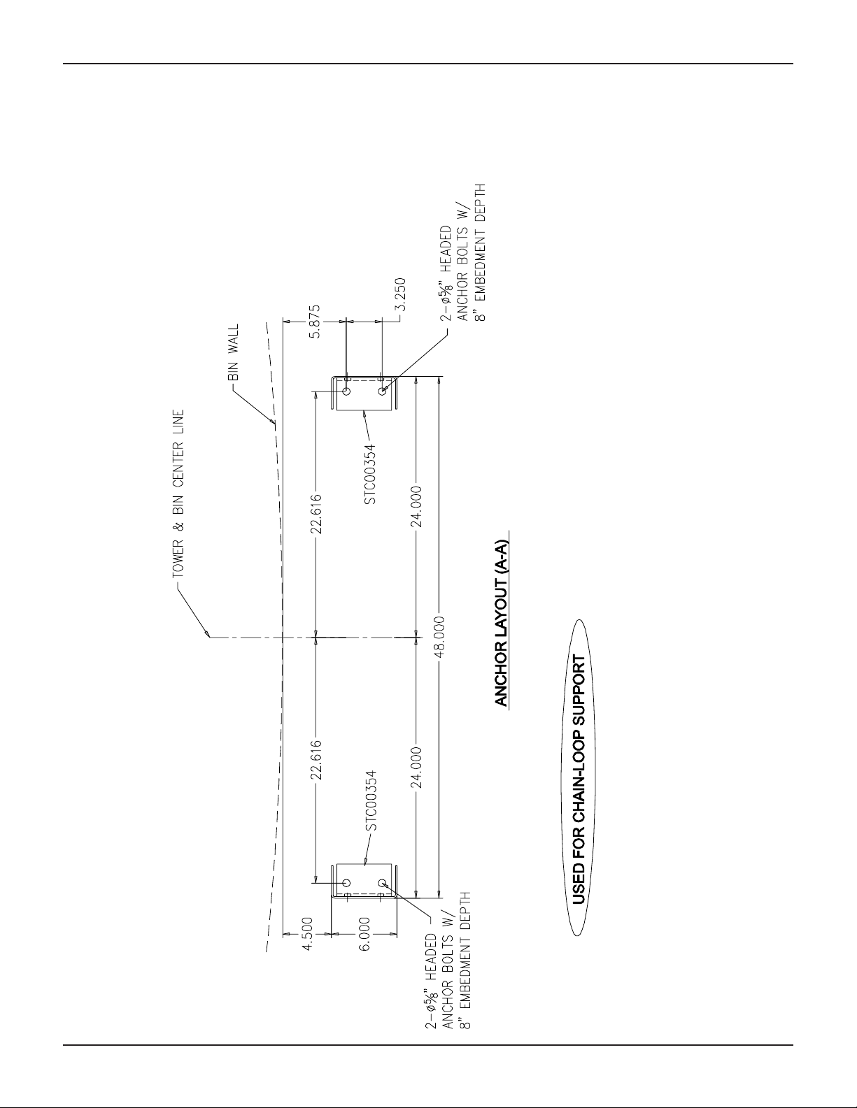
Anchor Bolt Lay out for
Chain-Loop Support
NOTE: Tower & bin
center are the same.
6 PNEG-1412 Two Leg Towers
Page 7
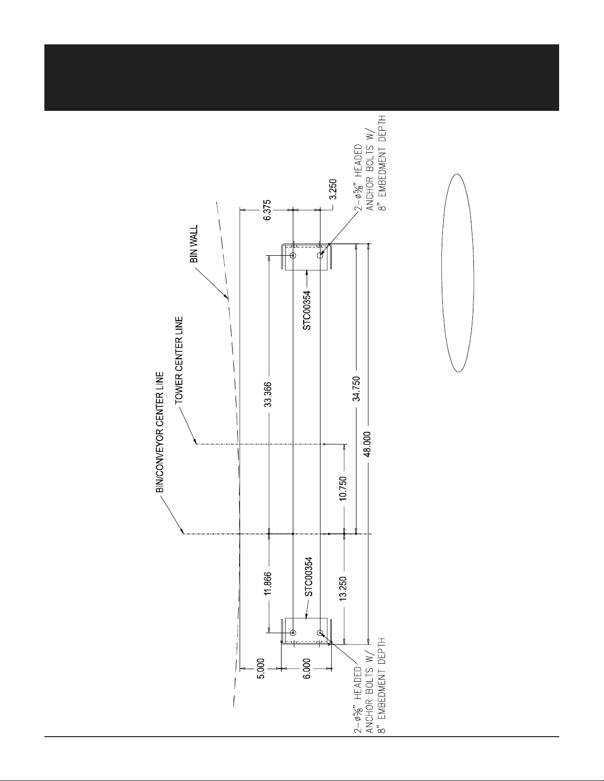
Anchor Bolt Lay out for
Catwalk Support
USED FOR CATWALK SUPPORT
ANCHOR LAYOUT (A-A)
NOTE: Tower Center
is DIFFERENT from
bin center.
PNEG-1412 Two Leg Towers 7
Page 8
Lateral Brack et to Bin for
Chain Loop Support
USED FOR CHAIN-LOOP SUPPORT
TOWER PLAN (B-B)
NOTE: Tower & bin
center are the same.
8 PNEG-1412 Two Leg Towers
Page 9

Lateral Brack et to Bin for
Chain-Loop Support
USED FOR CHAIN-LOOP SUPPORT
NOTE: Tower & bin
center are the same.
FRONT VIEW
PNEG-1412 Two Leg Towers 9
SIDE VIEW
Page 10

Lateral Brack et to Bin for
Catwalk Support
USED FOR CATWALK SUPPORT
TOWE R PLAN (B-B)
NOTE: Tower Center
is DIFFERENT from
bin center.
10 PNEG-1412 Two Leg Towers
Page 11

Lateral Brack et to Bin for
Catwalk Support
USED FOR CATWALK SUPPORT
NOTE: Tower Center
is DIFFERENT from
bin center.
FRONT/ BACK VIEW
PNEG-1412 Two Leg Towers 11
SIDE VIEW
Page 12

Assemble Bottom Angle Joints to Columns
1. S tart assembly by taking the 2 bottom columns (STC00348 -5' or STC00349 -10' depending on
height of tower) and attaching Bottom Angle Joint (STC00354) using (4) 1/2" x 1 HHCS bolts and (4)
1/2" hex nuts. (See Figure 1.) Note: Angles go to inside of leg channel.
Columns
(STC00348 - 10')
or
(STC00349 - 5')
Columns
(STC00348 - 10')
or
(STC00349 - 5')
1/2" Hex Nut
(S-3729)
1/2" Hex Nut
(S-3729)
Figure 1
1/2" x 1" HHCS Bolts
(S-4492)
Bottom Angle Joint
(STC00354)
Bottom Angle Joint
(STC00354)
12 PNEG-1412 Two Leg Towers
Page 13

FRONT/BACK VIEW SIDE VIEW
Bottom Column Sections with Bottom Angle Joints
PNEG-1412 Two Leg Towers 13
Page 14

Pre-Measuring for Alignment
This step is to locate the placement
of the bin bracket. All bin bracket
bolts must line up on the “hill” of the
corrugation. If this “pre-measuring” is
done correctly , no adjustments
should be needed to align holes on
hills after the tower is lifted into
place.
ATTACHING LATERAL
BRACKET, BIN BRACKET, &
BACKING PLATE TO COLUMNS.
1. Align holes & attach lateral brackets (STC00355) to top of bottom
columns using (2) 1/2" x 1" bolts, (2)
1/2" flat washers, & (2) 1/2" hex nuts
for each column. NOTE: Bolt heads
go to inside of column. Do not
fully tighten bolts. (See Figure 2.)
Lateral Bracket
(STC00355)
1/2" Flat Washer
(S-2120)
Column
1/2" x 1" HHCS Bolt
(S-4492)
1/2" Hex Nut
(S-3729)
Figure 2
2. Attach bin brackets (STF00016)
and backing plates (STF00021) to
lateral brackets using (3) 3/8" x 1"
HHCS bolts, (3) spacers, (6) washers, and (3) hex nuts as shown in
Figure 3 for each column. NOTE:
Bolts should be placed in the
bottom half of the bin bracket
slots. Fasten only finger tight to
allow bin to settle.
Bin Bracket
(STF00016)
3/8" Hex Nut
(S-456)
Figure 3
Backing Plate
(STF00021)
3/8" Flat Washer
(S-248)
NOTE: These bolts are to be finger tight only and
should be placed in the bottom half of the slot.
3/8" Flat Washer
(S-248)
3/8" S pacer
(STF00022)
Bin Bracket SLOTS
3/8" x 1" HHCS Bolt
(S-8671)
Lateral Bracket
(STC00355)
Column
14 PNEG-1412 Two Leg Towers
Page 15

Pre-Measuring for Alignment (cont.)
3. T ake columns and set on foundation so anchor bolts go through angle
joints. The bin bracket bolt holes
should line up on the “hills” of the
corrugation. (See Figure 4.) NOTE:
Do not attach to bin, this is for
alignment only .
4. If holes do not line up on the “hills”
of the corrugation, then you need to
remove the LATERAL BRACKET
(STC00355) from the column and reattach it to the column using the slots
in the lateral bracket. (See Figure 4.)
Then adjust the lateral bracket up or
down in the slots to line the holes in
BIN BRACKET (STF00016) on the
“hills” of the corrugation. Then fully
tighten lateral bracket bolts.
NOTE:
DO NOT use slots in BIN
BRACKET (STF00016) for adjust-
ment. Bolts holding lateral bracket, bin
bracket, & backing plate need to stay
in the bottom half of the slot to allow
the bin to settle. These bolts should
only be finger tight or damage may
occur to the bin.
3/8" x 1" HHCS Bolt
(S-8671)
“Hills” of
Corrugation
Bin Bracket
(STF00016)
Figure 4
Bin Bracket
(top hole)
(STF00016)
3/8" Hex Nut
(S-456)
Backing Plate
(STF00021)
LATERAL
BRACKET
SLOTS
Lateral Bracket
(STC00355)
5. T o make sure the next set of lateral
brackets, bin brackets, & backing
plates, line up on the “hills” of the
corrugation, measure form the top
120'
hole of the previously installed bin
bracket to the top hole on the bin
bracket being installed. The holes
should measure 120" apart. If they do
not, then adjust the lateral bracket
being installed following step #4
above, until the holes measure 120"
apart. (See Figure 5.) Repeat this
Bin Bracket
(top hole)
(STF00016)
step for all bin brackets as the columns are installed.
Figure 5
PNEG-1412 Two Leg Towers 15
Page 16

Top & Side Views
SIDE VIEW TOP VIEW
Lateral Bracket, Bin Bracket, & Backing Plate
16 PNEG-1412 Two Leg Towers
Page 17

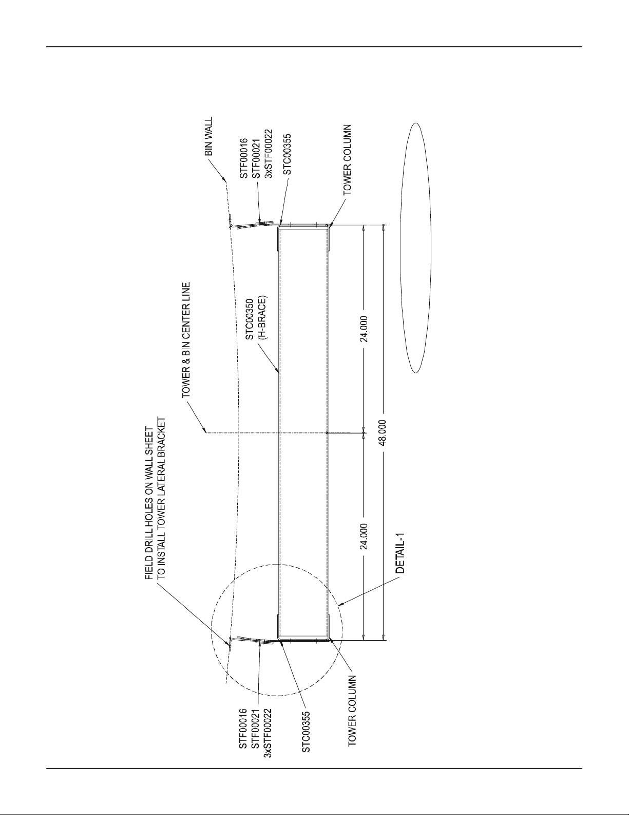
Diagonal “X” Bracing Configurations
“X”-Bracing is to be used in all upper sections of a tower.
All 20’-25’-30’ Tall Towers should all be “X”-braced, except for
the lower 10’ that is not “x” braced. (See examples above.)
All 35’ and taller towers should all be “X”-braced, except for
the lower 15’ that is not “X”-braced. (See examples above.)
PNEG-1412 Two Leg Towers 17
Page 18

Column Joints without Diagonal “X” Bracing
1. Place next columns on top of bottom columns.
2. Fasten top column to lateral brackets
(STC00355) using (2) 1/2" x 1" bolts, washers, &
hex nuts for each column. (See Figure 6.)
3. Align flange joint plates (STC00353) with holes
in columns and attach using (6) 1/2" x 1" HHCS
bolts & hex nuts. NOTE: Bolt heads go to inside
of channel. Skip top hole in bottom channel
until next step. DO NOT fully tighten bolts.
4. Attach “H” channel braces (STC00350) to the
inside of the columns and the flange joint plates
using (2) 1/2" x 1" HHCS bolts and hex nuts for
each column. (See Figure 6.)
1/2" Flat
Washer
(S-2120)
1/2" Hex Nut
(S-3729)
Bin Bracket
(STF00016)
Backing Plate
(STF00021)
1/2" x 1"
HHCS Bolt
(S-4492)
Lateral Bracket
(STC00355)
1/2" x 1" HHCS Bolt
(S-4492)
1/2" Hex Nut
(S-3729)
“H” Channel Brace
(STC00350)
Flange Joint Plate
(STC00353)
Figure 6
Column
18 PNEG-1412 Two Leg Towers
Page 19

Column Joints with Diagonal “X” Bracing
Review Diagonal “X” Bracing Configurations on
page 17 and determine the proper layout for your
bin diameter . Diagonal bracing covers 5' of
vertical height, additional “H” braces are to be
installed at these increments.
1. T o inst all diagonal bracing, align columns on
top of each other and fasten together using a web
plate (STC00352), (4) 1/2" x 1" HHCS bolts and
1/2" hex nuts for each column. NOTE: Bolt
heads go to inside of column. (See Figure 7.)
2. Using top hole, attach flange joint plates
(STC00353) to columns using (2) 1/2" x 1"
HHCS bolts & hex nuts for each column as
shown.
3. Attach (8) diagonal braces (STC00351) to
inside of both right and left columns and flange
joint plates using (8) 1/2" x 1" HHCS bolts and
hex nuts. One set of four braces go above H
Channel Brace (STC00350) and one set goes
below . (See Figure 7.) NOTE: Diagonal braces
are located on both front and back flanges.
4. Attach “H” Channel Brace (STC00350) to both
left and right columns and flange joint plates
(STC00353) using (4) 1/2" x 1" HHCS bolts and
nuts for each column. (See Figure 7.)
Flange Joint Plate
(STC00353)
1/2" Hex Nut
(S-3729)
1/2" Hex Nut
(S-3729)
Column
Web Plate
(STC00352)
1/2" x 1"
HHCS Bolt
(S-4492)
“H” Channel Brace
(STC00350)
Diagonal “X”
Brace
(STC00351)
Flange Joint Plate
(STC00353)
Diagonal “X”
Brace
(STC00351)
1/2" Hex Nut
(S-3729)
Column
Figure 7
PNEG-1412 Two Leg Towers 19
Page 20

Column Joints with Diagonal “X” Bracing (cont.)
Diagonal “X”
5. For “X” Bracing where a lateral bracket
is used instead of a web plate, see
Figure 8.
6. Install an “H” Channel Brace
(STC00350) to the top of the columns
and “X” bracing as shown using (4) 1/2" x
1" HHCS bolts and nuts. (See Figure 9.)
3/8" S pacer
(STF00022)
3/8" Hex
Nut (S-456)
3/8" Flat
Washer
(S-248)
Brace (STC00351)
3/8" x 1"
HHCS Bolt
(S-8671)
1/2" x 1"
HHCS
Bolt
(S-4492)
1/2" x 1"
HHCS Bolt
(S-4492)
“H” Channel Brace
(STC00350)
Diagonal “X” Brace
(STC00351)
Bin Bracket
(STF00016)
Figure 8
1/2" Flat
Washer
(S-2120)
Backing Plate
(STF00021)
1/2" Hex Nut
(S-3729)
Lateral Bracket
(STC00355)
1/2" x 1"
HHCS Bolt
(S-4492)
1/2" Hex Nut
(S-3729)
Column
1/2" Hex Nut
(S-3729)
Column
Figure 9
20 PNEG-1412 Two Leg Towers
Page 21

Diagonal “X” Bracing
PNEG-1412 Two Leg Towers 21
FRONT/BACK VIEW SIDE VIEW
Page 22

Straighten Columns and Stand Towers in Place
1. St art with one column and run a string from top to bottom, align all joints and straighten. T ighten all
hardware. Repeat process for both columns. NOTE:
bin bracket & backing plate to the lateral bracket. These bolts need to be finger tight only to
allow bin to settle.
2. When assembly is complete and hardware tightened. St and tower assembly upright and set in
place over anchor bolts. All bin brackets holes should line up on the hills of the corrugation. Field drill
through bin brackets into hills of corrugation and bolt the tower bin brackets to bin sidewall using
3/8" x 1" HHCS bolts & hex nuts. NOTE: Bolt heads go on outside of bin.
DO NOT tighten hardware that connects the
22 PNEG-1412 Two Leg Towers
Page 23

Catwalk Support Br ackets
DETAIL-2
SIDE VIEW TOP VIEW
PNEG-1412 Two Leg Towers 23
Page 24

NOTES
24 PNEG-1412 Two Leg Towers
Page 25

The GSI Group, Inc. Warranty
THE GSI GROUP, INC. (“GSI”) WARRANTS ALL PRODUCTS WHICH IT MANUFACTURES TO
BE FREE OF DEFECTS IN MATERIAL AND WORKMANSHIP UNDER NORMAL USAGE AND
CONDITIONS FOR A PERIOD OF 12 MONTHS AFTER RETAIL SALE TO THE ORIGINAL END
USER. THE PURCHASER’S SOLE REMEDY AND GSI’S ONLY OBLIGATION SHALL BE TO
REPAIR OR REPLACE, AT GSI’S OPTION AND EXPENSE, PRODUCTS THAT, IN GSI’S SOLE
JUDGMENT, CONTAIN A MATERIAL DEFECT DUE TO MATERIALS OR WORKMANSHIP.
ALL DELIVERY AND SHIPMENT CHARGES TO AND FROM GSI’S FACTORY WILL BE
PURCHASER’S RESPONSIBILITY. EXPENSES INCURRED BY OR ON BEHALF OF THE
PURCHASER WITHOUT PRIOR WRITTEN AUTHORIZATION FROM AN AUTHORIZED
EMPLOYEE OF GSI SHALL BE THE SOLE RESPONSIBILITY OF THE PURCHASER.
EXCEPT FOR THE LIMITED WARRANTY EXPRESSED ABOVE, GSI MAKES NO FURTHER
WARRANTY OF ANY KIND, EXPRESS OR IMPLIED, INCLUDING, WITHOUT LIMITATION,
WARRANTIES OF MERCHANTABILITY OR FITNESS FOR A PARTICULAR PURPOSE OR
USE IN CONNECTION WITH (I) PRODUCT MANUFACTURED OR SOLD BY GSI OR (ii) ANY
ADVICE, INSTRUCTION, RECOMMENDATION OR SUGGESTION PROVIDED BY AN AGENT,
REPRESENTATIVE OR EMPLOYEE OF GSI REGARDING OR RELATED TO THE
CONFIGURATION, INSTALLATION, LAYOUT, SUITABILITY FOR A PARTICULAR PURPOSE,
OR DESIGN OF SUCH PRODUCTS.
GSI SHALL NOT BE LIABLE FOR ANY DIRECT, INDIRECT, INCIDENTAL OR
CONSEQUENTIAL DAMAGES, INCLUDING, WITHOUT LIMITATION, LOSS OF ANTICIPATED
PROFITS OR BENEFITS. PURCHASER’S SOLE AND EXCLUSIVE REMEDY IS AS SET FORTH
IN THE LIMITED WARRANTY EXPRESSED ABOVE, WHICH SHALL NOT EXCEED THE
AMOUNT PAID FOR THE PRODUCT PURCHASED. THIS WARRANTY IS NOT
TRANSFERABLE AND APPLIES ONLY TO THE ORIGINAL PURCHASER. GSI SHALL HAVE
NO OBLIGATION OR RESPONSIBILITY FOR ANY REPRESENTATIONS OR WARRANTIES
MADE BY OR ON BEHALF OF ANY DEALER, AGENT OR DISTRIBUTOR OF GSI.
GSI ASSUMES NO RESPONSIBILITY FOR CLAIMS RESULTING FROM ERECTION DEFECTS
OR UNAUTHORIZED MODIFICATIONS TO PRODUCTS WHICH IT MANUFACTURED.
MODIFICATIONS TO PRODUCTS NOT SPECIFICALLY DELINEATED IN THE MANUAL
ACCOMPANYING THE EQUIPMENT AT INITIAL SALE WILL NULLIFY THE PRODUCT
WARRANTY THAT MIGHT HAVE BEEN OTHERWISE AVAILABLE.
THE FOREGOING WARRANTY SHALL NOT EXTEND TO PRODUCTS OR PARTS WHICH
HAVE BEEN DAMAGED BY NEGLIGENT USE, MISUSE, ALTERATION OR ACCIDENT. THIS
WARRANTY EXTENDS SOLELY TO ONLY PRODUCTS MANUFACTURED BY GSI. THIS
WARRANTY IS EXCLUSIVE AND IN LIEU OF ALL OTHER WARRANTIES EXPRESS OR
IMPLIED. GSI RESERVES THE RIGHT TO MAKE DESIGN OR SPECIFICATION CHANGES AT
ANY TIME.
PRIOR TO INSTALLATION, PURCHASER HAS THE RESPONSIBILITY TO COMPLY WITH
ALL FEDERAL, STATE AND LOCAL CODES WHICH MAY APPLY TO THE LOCATION AND
INSTALLATION OF PRODUCTS MANUFACTURED OR SOLD BY GSI.
PHLEGAL: #1832020 v1 (139LG01!.DOC) (revised December 2005)
Page 26

This Equipment shall be installed in accordance
with the curr ent installation codes and applicable
regulations which should be carefully followed in
all cases. Authorities having jurisdiction should be
consulted before installation occurs.
Copyright © 2005 by The GSI Group
Printed in the USA
1004 East Illinois Street
Assumption, IL 62510
217-226-4421 Phone
800-800-5329 F AX
 Loading...