

Page 1

PNEG-1 40 4
Vision Series Model 2300
Portable Dryers
Parts Manual
PNEG-1404
Date: 12-19-12
Page 2

2 PNEG-1404 Vision Series Model 2300 Portable Dryers
Page 3

Table of Contents
Contents
Chapter 1 Bottom Module ..................................................................................................................................... 4
Frame Assembly ................................................. ... ... .... ... ... .......................................... ... ..................... 4
Frame/Auger Trough/Hopper Bulkheads .............................................................................................. 7
Metering Rolls and their Placement in the Dryer ................................................................................... 9
Inside (Plenum) Screens/Plenum Closure Doors ................................................................................ 11
Meter Roll Upper Shield Assembly ..................................................................................................... 12
Outside Screens/Meter Roll Access Doors ......................................................................................... 13
Plenum Divider .................................................................................................................................... 14
Clean Out Doors ................................................................................................................................. 15
Module Support Pads/Stiffener Attach Angles .................................................................................... 17
Front Ladder Assembly ....................................................................................................................... 19
Rear Ladder Assembly ........................................................................................................................ 20
Front End Panels/Fan Support/Grill Guards ....................................................................................... 21
Rear End Panels/Rear Access Door ................................................................................................... 22
Bottom Auger ...................................................................................................................................... 23
Bottom Auger Drive ....................................................................................................................... ... ... 25
Metering Roll Drive .............................................................................................................................. 28
Chapter 2 Top Module ......................................................................................................................................... 30
Frame/Lower Basket ........................................................................................................................... 30
Inside (Plenum) Screens/Outside Screens ............................................ .... ... ... ... ................................ 34
Stiffener Attach Angles/Crane Brackets .............................. ............................................. ................... 35
Front End Panels/Fan Support/Grill Guard and Venturi ...................................................................... 36
Rear End Panels/Rear Access Door/Front and Rear Ladders ............................................................ 37
Top Auger with Wet Bin Assembly ...................................................................................................... 39
Top Auger Drive .................................................................................................................................. 42
Chapter 3 Fan/Heaters ......................................................................................................................................... 44
Fan/Heater Housing Assembly ................. ... .... ... ... ... .... ... ... ... .... ... ... ... ... ............................................. 44
Fan Motor/Motor Mount/Fan Blade ..................................................................................................... 46
Air Mixer Assemblies ........................................................................................................................... 48
Flame Probe/Ignitor/Burner Assemblies ............................................................................................. 49
LP Pipe Train Assemblies ................................................................................................................... 53
NG Pipe Train Assemblies .................................................................................................................. 59
Fan/Heater Orifices .......................................... ... ... ... .......................................... .... ... ... ... ....... ............ 62
LP Supply Line (Bottom Module) ........................................................................................................ 63
LP Supply Line (Top Module) .............................................................................................................. 65
NG Supply Line (Bottom Module) ....................................................................................................... 66
NG Supply Line (Top Module) ............................................................................................................. 68
Chapter 4 Electrical (Bottom Module) ................................................................................................................ 69
Plenum, Right Grain High-Limit Thermostat and Operator Light ........................................................ 69
Left Grain High-Limit Thermostat ........................................... .... ... ... ............................................. ... ... 70
Lower Junction Box/Meter Roll Motor Conduit/Rear Discharge Conduit ............................................ 72
Air Switch Assembly ............................................................................................................................ 74
Chapter 5 Electrical (Top Module) .................................. ... ... ... .... ... ... ... .... ... ... .................................................... 75
Lower Junction Boxes with Grain High-Limit Thermostats .................................................................. 75
Upper Junction Box/Fill Switch Assembly/Plenum High-Limit .......................... ....................... ............ 77
Wire Way Assembly .. .......................................... ... ... .... ... ... ... .... ... ... ................................................... 79
Chapter 6 Control Boxes ..................................................................................................................................... 80
Fan/Heater Electrical Box ...... ... ... .... ... ... ... ... .... ... ... .......................................... ... .... ... ... ... ................... 80
Control Box Switch Panel .................................................................................................................... 82
Lower Control Box Back Panel ........................................................................................................... 83
Control Box Switch Panel (Rear) ........................................................................................................ 84
Upper Control Box Panel .................................................................................................................... 86
Chapter 7 Warranty .............................................................................................................................................. 93
PNEG-1404 Vision Series Model 2300 Portable Dryers 3
Page 4
1. Bottom Module
Right side
3
4a
1a
3
1
5
5
3
5
5
3
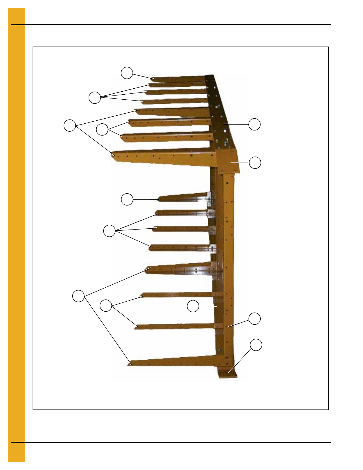
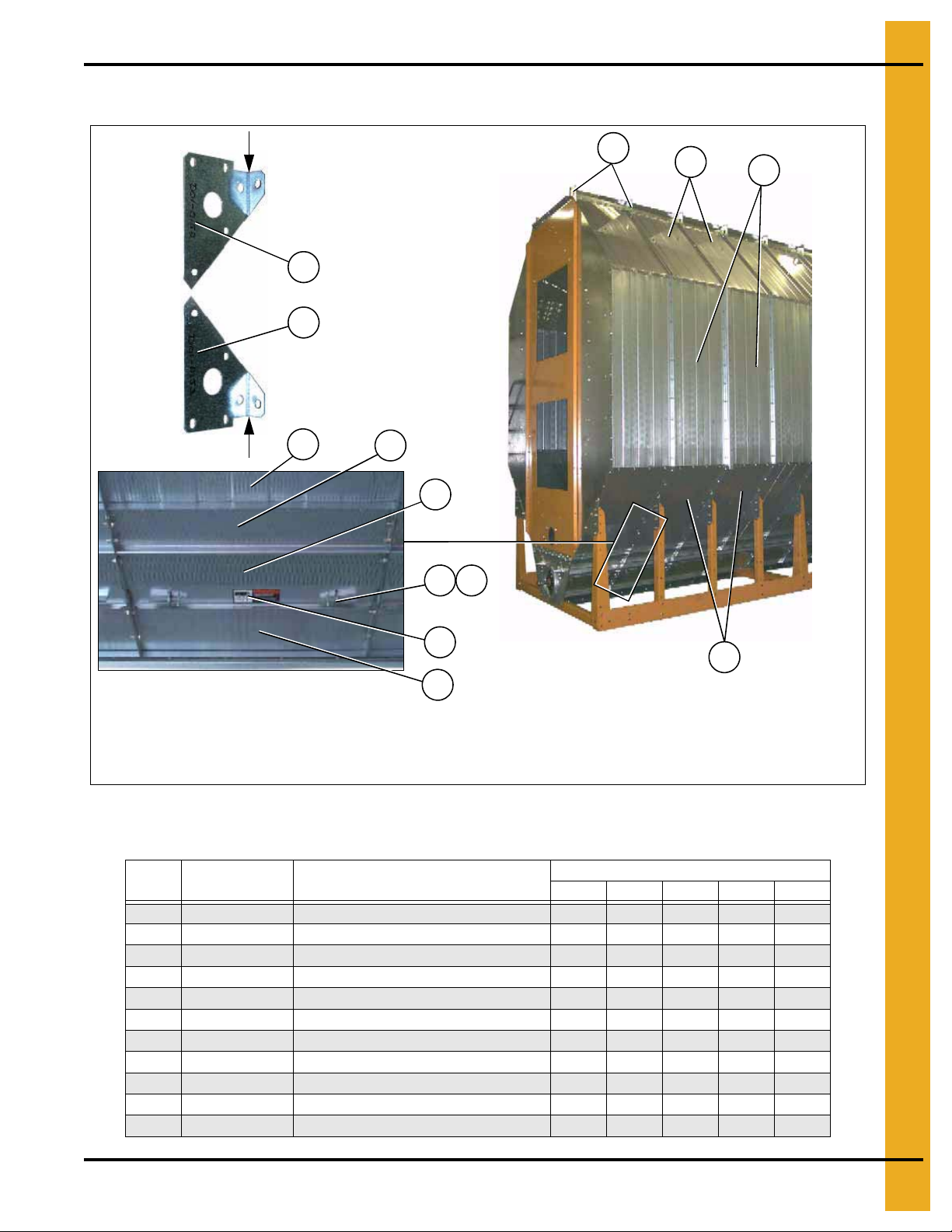
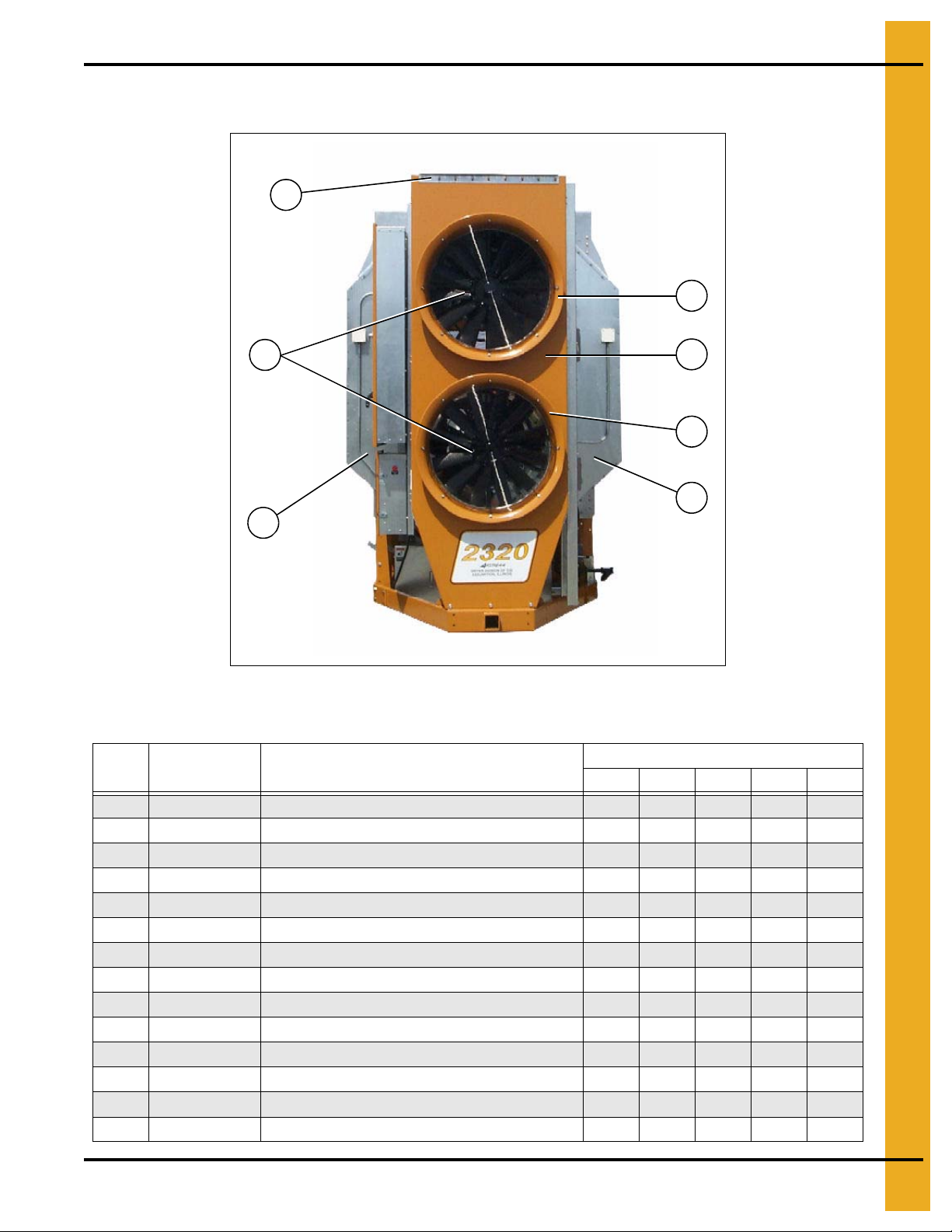
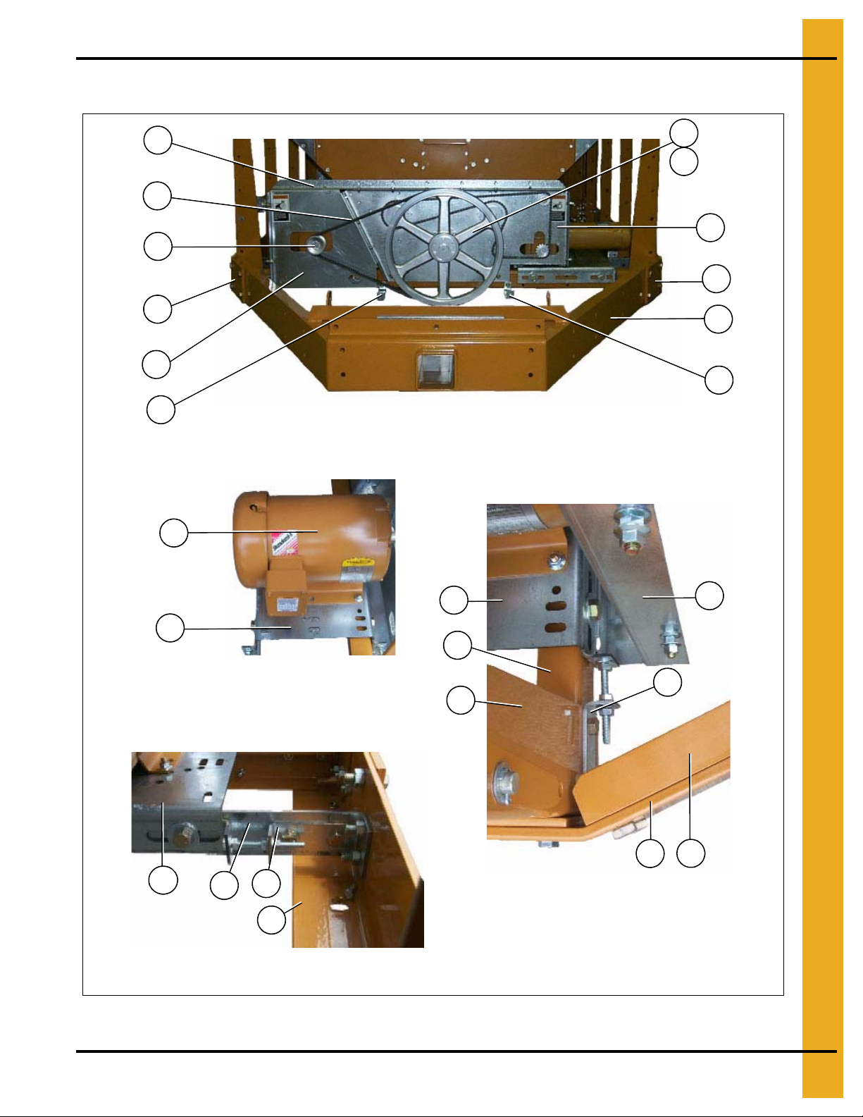
The fan/heater end of the dryer is considered by GSI as the front end of the dryer. (The foreground
of this photograph is the front end. Right and left sides are labeled above.)
Left side
2
4
Frame Assembly
Figure 1A Frame Assembly (View from fan/heater end with hitch weldment removed.)
NOTE: The parts pointed out on this page are listed on Page 6.
4 PNEG-1404 Vision Series Model 2300 Portable Dryers
Page 5
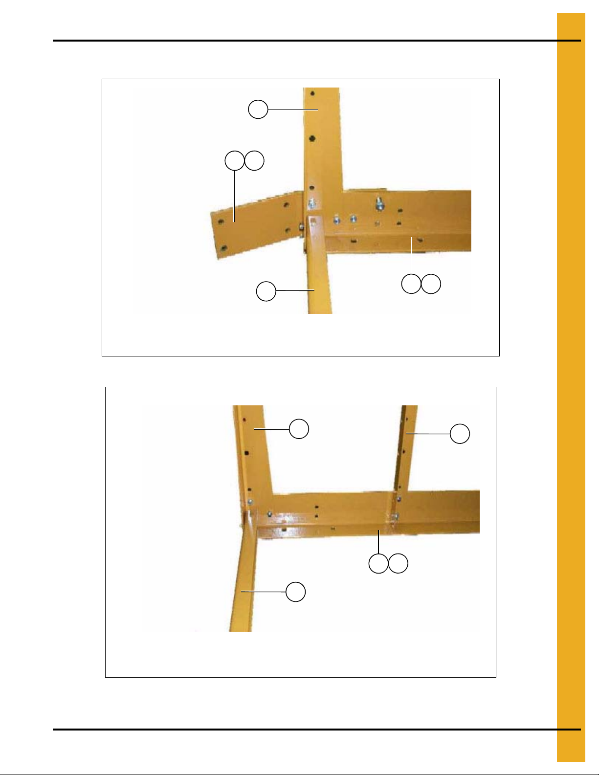
Frame Assembly (Continued)
2
1
1a
NOTE: The right front corner is shown in the photo. For left front corner all parts are the same
except for the hitch bracket (use 1a for the left side), and the frame rail (use 4a for the left side).
4
4a
3
2
5
NOTE: The left rear corner is shown in the photo. For right rear corner all parts are the same
except for the frame rail (use 4 for the right side).
3
4
4a
1. Bottom Module
Figure 1B Right Front Corner of Frame
PNEG-1404 Vision Series Model 2300 Portable Dryers 5
Figure 1C Left Rear Corner of Frame
Page 6
1. Bottom Module
5
3
2
4a
4
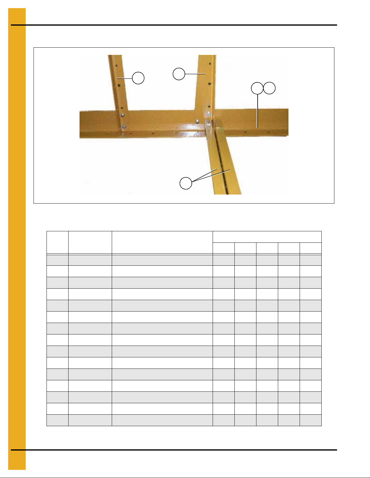
Frame Assembly (Continued)
Figure 1D Center Cross Ties
Frame Assembly Parts List (See Figure 1A, 1B, 1C and 1D)
Ref # Part # Description
1 D01-0012 Hitch Bracket Right 1 1 1 1 1
1a D01-0011 Hitch Bracket Left 1 1 1 1 1
2 D01-0008 Front and Rear Frame Tie Channel 4 4 4 6 6
3 D01-0007 Corner Leg Portable Dryer 6 6 6 8 8
4 D21-0011 Frame Rail, 14' Right 1
4 D31-0044 Frame Rail, 18' Right 1
4 D61-0002 Frame Rail, 20' Right 1
4 D101-0002 Frame Rail, 22' Right 1
4 D71-0001 Frame Rail, 26' Right 1
4a D21-0010 Frame Rail, 14' Lef t 1
4a D31-0043 Frame Rail, 18' Lef t 1
4a D61-0001 Frame Rail, 20' Lef t 1
2314 2318 2320 2322 2326
Qty
4a D101-0001 Frame Rail, 22' Lef t 1
4a D71-0002 Frame Rail, 26' Lef t 1
5 D01-0005 Side Leg Portable Dryer 10 14 16 16 20
6 PNEG-1404 Vision Series Model 2300 Portable Dryers
Page 7
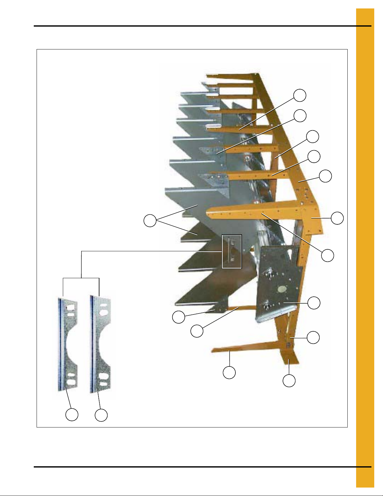
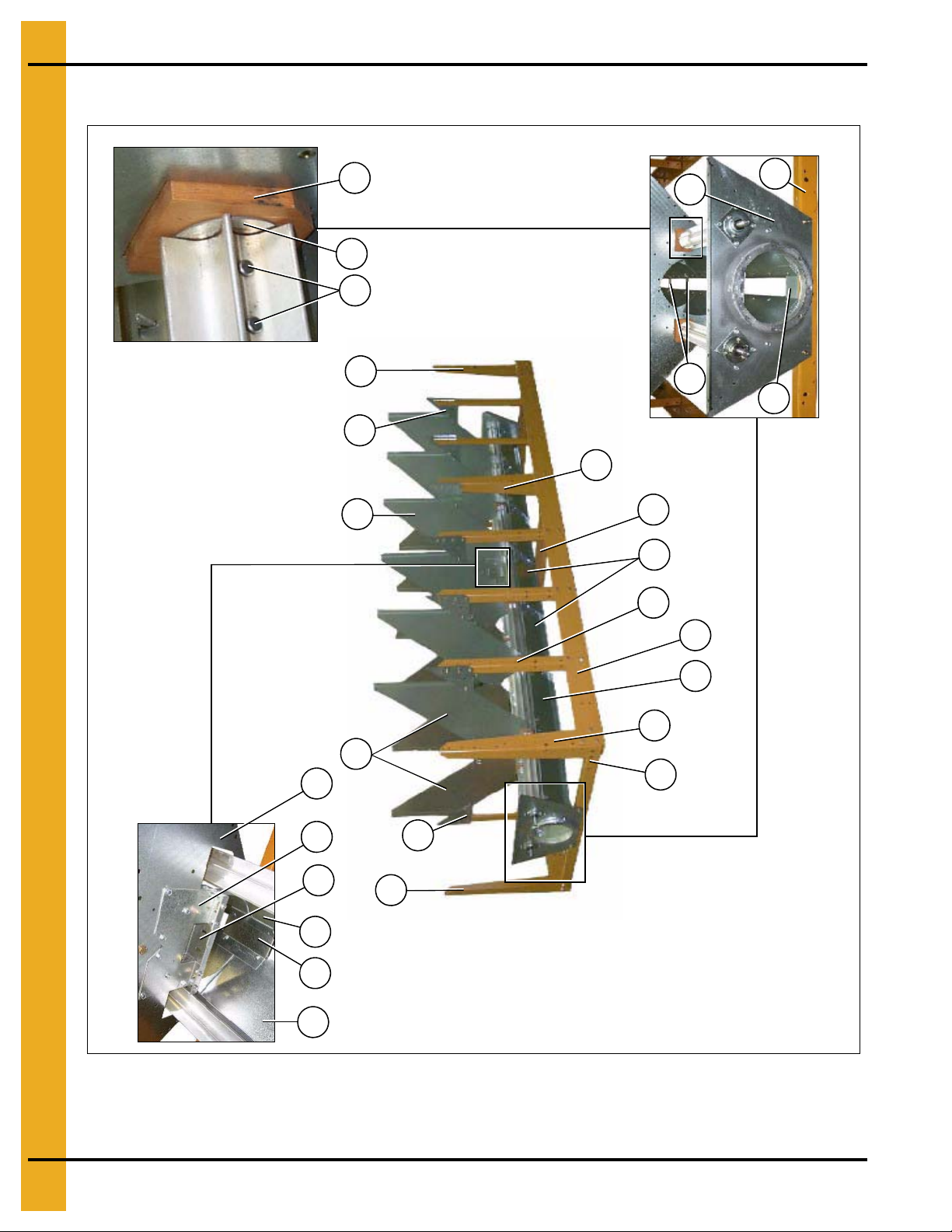
Frame/Auger Trough/Hopper Bulkheads
2
1
3
6
4
9
5
11
8
6
4
5
6
7
9
10
NOTE: The hole pattern of the plenum closure door angles.
This will distinguish between L.H. and R.H.
1. Bottom Module
Figure 1E Dryer Frame and Lower Basket Assembly
(View from the front end of the dryer looking down the left side.)
NOTE: The parts pointed out on this page are listed on Page 10.
PNEG-1404 Vision Series Model 2300 Portable Dryers 7
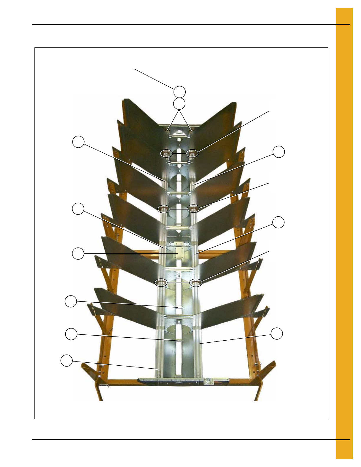
Page 8
1. Bottom Module
Wooden meter roll support bearing.
The meter roll sections are spliced
together with a meter roll splice shaft
(part #D31-0046) that passes through
the support bearing assembly.
Center hanger bearing
support and cross
channel seal plate.
6
4
3
6
9
12
5
11a
12
6
9
6
4
3
3
15
14
12
13
12
18
17
16
Discharge bearing plate
20
21
9
19
Frame/Auger Trough/Hopper Bulkheads (Continued)
Figure 1F Dryer frame and lower basket assembly
(View from the rear end of the dryer looking up the ri ght side.)
NOTE: The parts pointed out on this page are listed on Page 10.
8 PNEG-1404 Vision Series Model 2300 Portable Dryers
Page 9
Metering Rolls and their Placement in the Dryer
This end is the front (fan/heater) end of the dryer.
NOTE: Ref #22 at the rear of dryer is a front section meter roll
that is used as a rear section on 16' and 20' dryers only.
22
24
23
23
22
23
23
13
19
22
19
Meter roll bearing
Ref # 16, 17 and 18
on Page 10.
Meter roll bearing
Ref # 16, 17 and 18
on Page 10.
Meter roll bearing
Ref # 16, 17 and 18
on Page 10.
1. Bottom Module
PNEG-1404 Vision Series Model 2300 Portable Dryers 9
Figure 1G
Page 10

1. Bottom Module
Frame/Auger Trough/Hopper Bulkheads and Metering Rolls Parts List
(See Figure 1E, 1F and 1G)
Ref # Part # Description
2314 2318 2320 2322 2326
1 D01-1 1 36Y Plenum Closure Door Angle, R.H. 6 8 9 10 12
2 D01-1136X Plenum Closure Door Angle, L.H. 7 9 10 11 13
3 D01-0109 Hopper Bulkhead 12 16 18 20 24
4D01-0004 Gusset Plate 1620222428
5 D01-0005 Side Leg 10 14 16 16 20
6 D01-0007 Corner Leg 6 6 6 8 8
7 D01-0011 Hitch Bracket, L.H. 1 1 1 1 1
8 D01-0012 Hitch Bracket, R.H. 1 1 1 1 1
9 D01-0008 Front and Rear Frame Tie Channel 4 4 4 6 6
10 D01-2435 Front Bearing Plate 2008 1 1 1 1 1
11 D21-0011 Frame Rail, 14' Right 1
11 D31-0044 Frame Rail, 18' Right 1
11 D61-0002 Frame Rail, 20' Right 1
11 D101-0002 Frame Rail , 22' Right 1
11 D71-0001 Frame Rail, 26' Right 1
Qty
11a D21-0010 Frame Rail, 14' Left 1
11a D31-0043 Frame Rail, 18' Left 1
11a D61-0001 Frame Rail, 20' Left 1
11a D101-0001 Frame Rail, 22' Left 1
11a D71-0002 Frame Rail, 26' Left 1
12 D01-0048 Trough Panel 14 18 20 22 26
13 D01-1512 Plate, Cross Channel Seal w/ Tabs 1 1 1 2 2
14 D01-1291 Hanger Bearing “C” Channel 1 1 1 2 2
15 D01-1290 Hanger Bea ri ng “J” Plate 2 2 2 4 4
16 D02-0028 Clevis Pin 5/16" x 1-3/4" 32 40 40 48 56
17 D31-0148 Meter Roll Washer 16 20 20 24 28
18 D02-0061 Meter Roll Support Bearing 6 8 8 10 12
19 D01-0177 Support Strap 7 9 10 1 1 13
20 D01-1511 Plate, End Channel Seal w/ Tab 2 2 2 2 2
21 D01-2434 Disch arge Plate 2008 1 1 1 1 1
22 D31-0031 Meter Roll, Front 2 2 4 2 2
23 D31-0030 Meter Roll, Intermediate 4 6 6 8 10
24 D31-0029 Meter Roll, Rear 2 2 2 2
Use this part number list for all parts on Pages 7, 8 and 9.
10 PNEG-1404 Vision Series Model 2300 Portable Dryers
Page 11
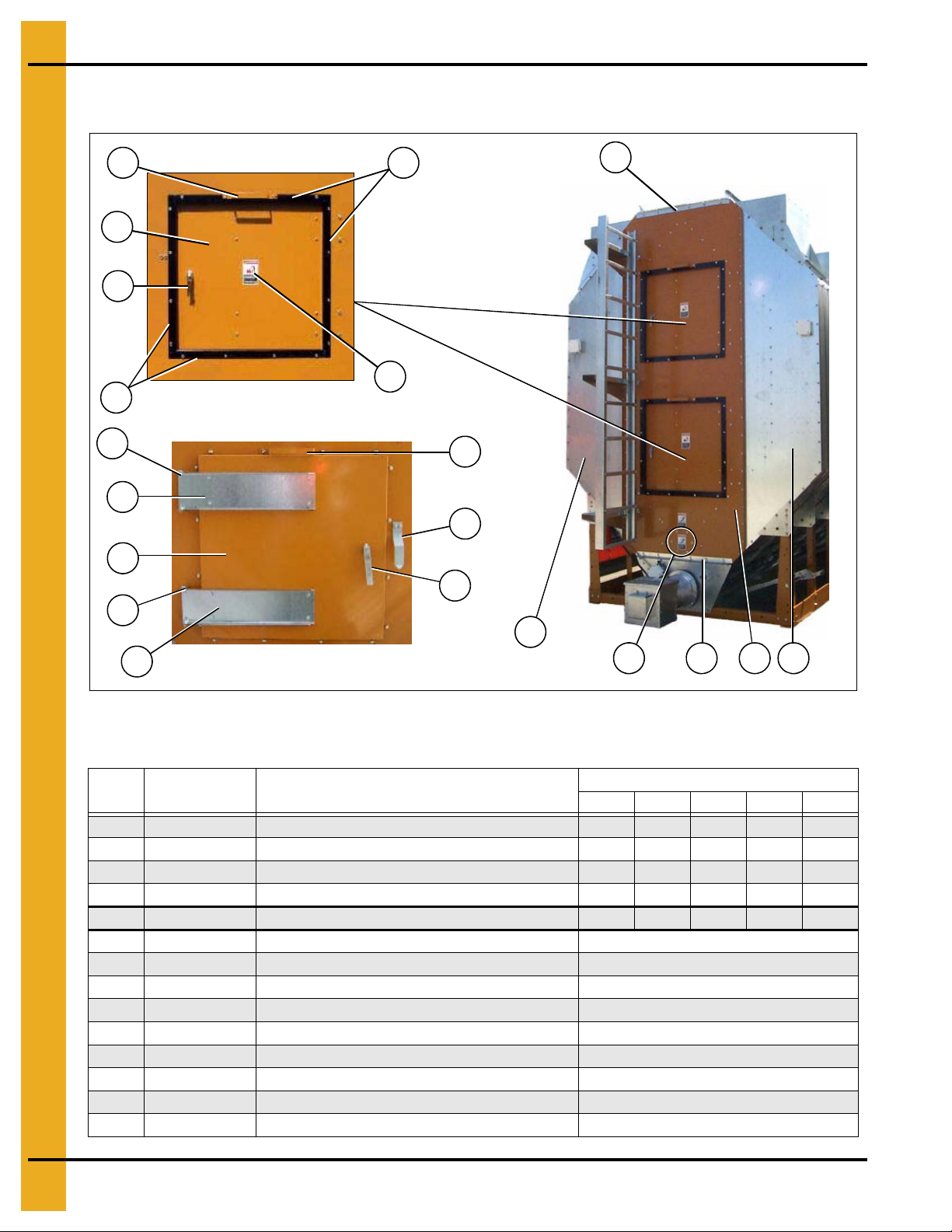
Inside (Plenum) Screens/Plenum Closure Doors
20a
This photograph was taken before the front plenum end panel and
outer screens were installed in order to get a good view of the inside
screens and bulkheads.
Plenum closure door. There are two (2) different plenum closure
doors. The door shown in the photograph is the rear plenum closure
door and is the rear most plenum closure door, Ref #20 (just inside
the rear access door), all others are Ref #20a. NOTE: Ref #22 is the
plenum closure door rear frame angle.
20
21
22
2
5
1
7
15
9
16
10
12
14
13
11
8
6
5
3
4
3
23
23
10
7
1. Bottom Module
Figure 1H Plenum Screens and Bulkheads (View from front end)
PNEG-1404 Vision Series Model 2300 Portable Dryers 11
Page 12
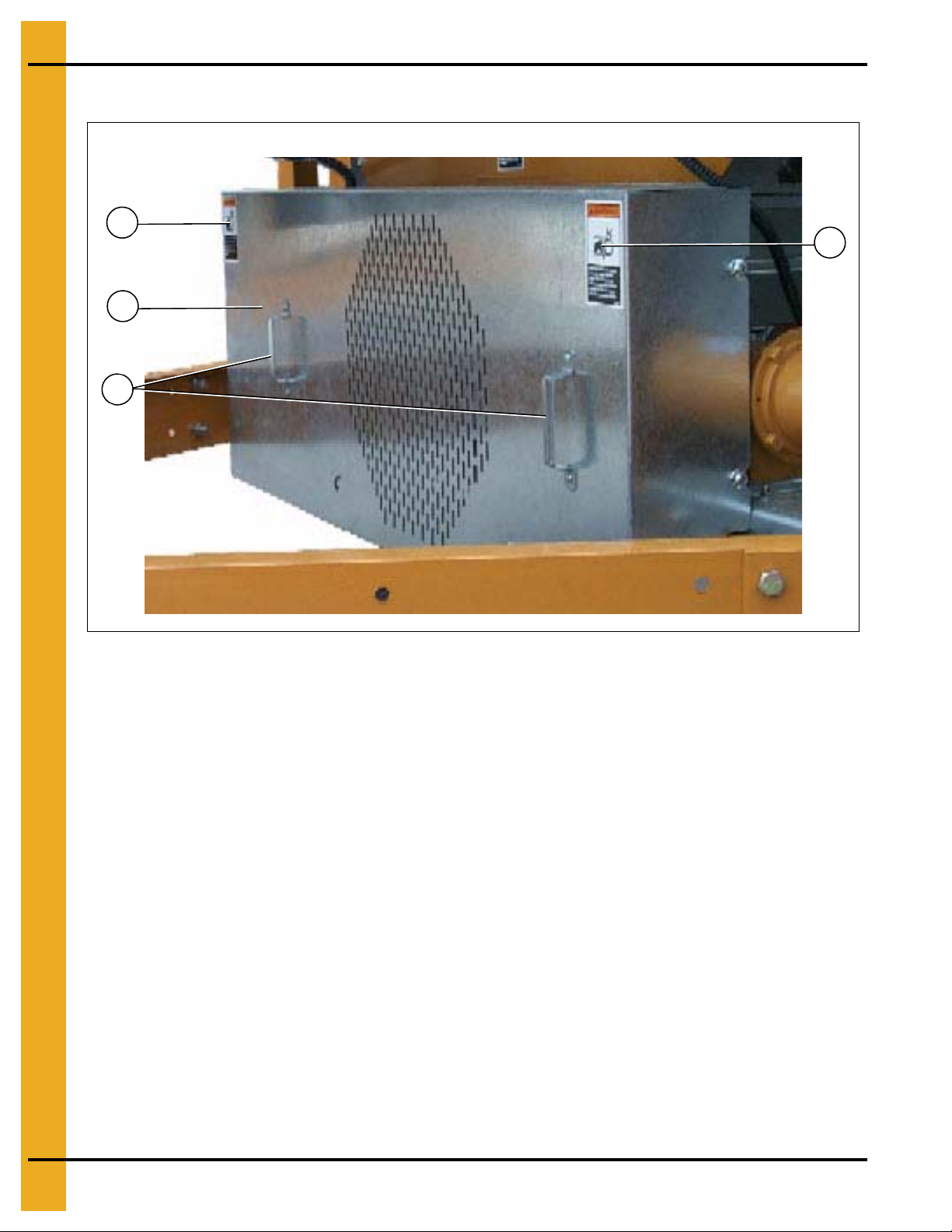
16
17
18
19
19
18
17
1. Bottom Module
Meter Roll Upper Shield Assembly
Figure 1I Close Up of Meter Roll Upper Shield Assembly
Inside (Plenum) Screens/Plenum Closure Doors
Assembly Parts List (See Figure 1H and 1I)
Ref # Part # Description
1 D31-0055 Column Bulkhead 12 16 18 20 24
2 D01-0101 Garner Bulkhead 12 16 18 20 24
3 D31-0307 Column End Panel 4 4 4 4 4
4 D01-0126 Screen, Plenum Top, Gauge, 094 14 18 20 22 26
5 D31-0012 Screen, Plenum Wall, Gauge, 094 14 18 20 22 26
6 D01-1225 Screen, Plenum Bottom, Gauge, 094 14 18 20 22 26
7 D01-0004 Gusset Plate 16 20 22 24 28
8 D21-0011 Frame Rail, 14' Right 1
8 D31-0044 Frame Rail, 18' Right 1
8 D61-0002 Frame Rail, 20' Right 1
8 D101-0002 Frame Rail, 22' Right 1
8 D71-0001 Frame Rail, 26' Right 1
9 D21-0010 Frame Rail, 14' Left 1
9 D31-0043 Frame Rail, 18' Left 1
9 D61-0001 Frame Rail, 20' Left 1
9 D101-0001 Frame Rail, 22' Left 1
9 D71-0002 Frame Rail, 26' Left 1
10 D01-0007 Corner Leg Portable Dryer 66688
11 D01-0012 Hitch Bracket Right 1 1 1 1 1
12D01-0011 Hitch Bracket Left 11111
13 D01-0008 Front and Rear Frame Tie Channel 4 4 4 6 6
14 D01-2435 Front Bearing Plate 2008 11111
15 D01-0005 Side Leg Portable Dryer 10 14 16 16 20
16 D01-0109 Hopper Bulkhead 12 16 18 20 24
17 D01-0050P Connector Sheet, Perforated 14 18 20 22 26
*18 and 19 D01-1180 Meter Roll Upper Shield Assembly 14 18 20 22 26
18 D01-0431 Meter Roll Strike Off Plate 1/Assembly
19 D01-1226 Meter Roll Shield 1995 Style 1/Assembly
20 D01-1214 Plenum Closure Door, Rear 1 1 1 1 1
20a D01-1134 Plenum Closure Door 6 8 9 10 12
21 DC-974 Danger Foot in Auger Decal 2 2 2 2 2
22 D01-1217 Plenum Closure Door Rear Frame Angle 11111
23 D61-0038 Bulkhead Stiffener Bar 24 32 36 40 48
* Ref #18 and 19 together make up the meter roll upper shield assembly.
2314 2318 2320 2322 2326
Qty
12 PNEG-1404 Vision Series Model 2300 Portable Dryers
Page 13
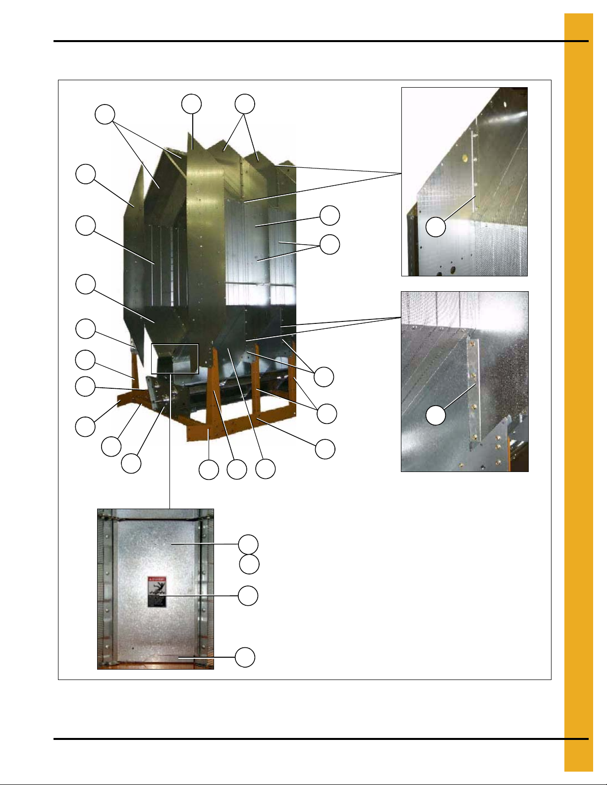
Outside Screens/Meter Roll Access Doors
*NOTE: Ref #4 is pointing to the top edge angle gusset. There are two (2) types of gusset on the dryer. The photo on top
left will help distinguish the difference between the two (2). The arrows are pointing to a tab on the gusset that makes
them different (tabs are “bent” up in photo). Ref #4a is used in two (2) places only; 1) front right of dryer, 2) rear left of
dryer, all others are Ref #4.
Meter roll access door
3
4
1
2
4a
4
3
5
6
7 8
9
10
*
1. Bottom Module
Figure 1J
Outside Screens/Meter Roll Access Doors Parts List
Ref # Part # Description
1 D01-0127 Screen, Roof, Gauge, 094 14 18 20 22 26
2 D31-0013 Screen, Outside Wall, Gauge, 094 14 18 20 22 26
3 D01-0128 Screen, Hopper, Gauge, 094 14 18 20 22 26
4 D01-0152 L.H. Top Angle Gusset 12 16 18 20 24
4a D01-0153 R.H. Top Angle Gusset 2 2 2 2 2
5 D01-0050P Connector Sheet, Perforated 14 18 20 22 26
6 D01-0045P Access Door, Perforated 14 18 20 22 26
7D01-0039 Door Latch 2836404452
8 S-6552 Pin, Hair Clip 3/32" ZN Plated 28 36 40 44 52
9 DC-1229 Decal, Warning Meter Roll Rot. 14 18 20 22 26
PNEG-1404 Vision Series Model 2300 Portable Dryers 13
10 D01-0048 Trough Panel Weldment 14 18 20 22 26
2314 2318 2320 2322 2326
Qty
Page 14
1. Bottom Module
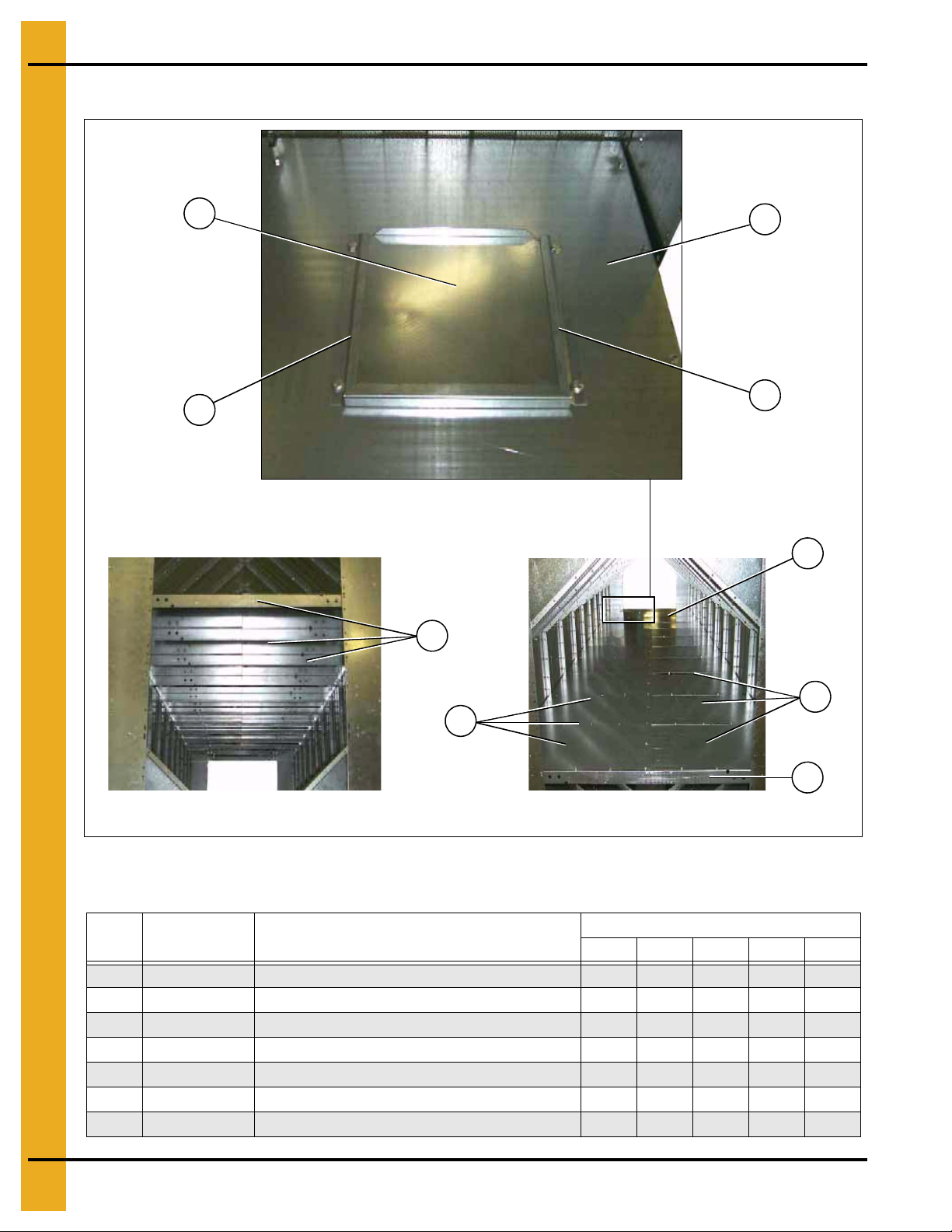
Right rear plenum divider section with clean out door
Plenum divider support channels Plenum divider floor sections
4
5
4
6
7
1
2
3
2
Plenum Divider
Figure 1K
Ref # Part # Description
1 D31-0259 Plenum Divider Clean Out Door 1 1 1 1 1
2D31-0260Clean Out Door Guide Plenum 22222
3 D61-0028 Plenum Divider R.H. : Rear 1 1 1 1 1
4 D61-0024 Plenum Support Channel 8 10 11 12 14
5 D61-0026 Plenum Divider R.H. 6 8 9 10 12
6 D61-0025 Plenum Divider L.H. 6 8 9 10 12
7 D61-0027 Plenum Divider L.H. : Rear 1 1 1 1 1
Plenum Divider Parts List
Qty
2314 2318 2320 2322 2326
14 PNEG-1404 Vision Series Model 2300 Portable Dryers
Page 15
Clean Out Doors
5
3a
7
NOTE: Ref #9, 10 and 1 1 together create the clean out
door assembly. There are three (3) different clean out
door assemblies that are used on GSI Network dryers:
1) 3 Column clean out door assembly (D51-0077). Ref #8a
on the part # listing on Page 16.
2) 4 Column clean out door assembly (D11-0032). Ref #8b
on the part # listing on Page 16.
3) 5 Column clean out door assembly (D01-0349). Ref #8c
on the part # listing on Page 16.
A 5 column clean out door assembly (D01-0349) is shown in
the photograph above.
1
4
2
13
3
4
2
6
5
9
10
11
12
13
9
11
11
11
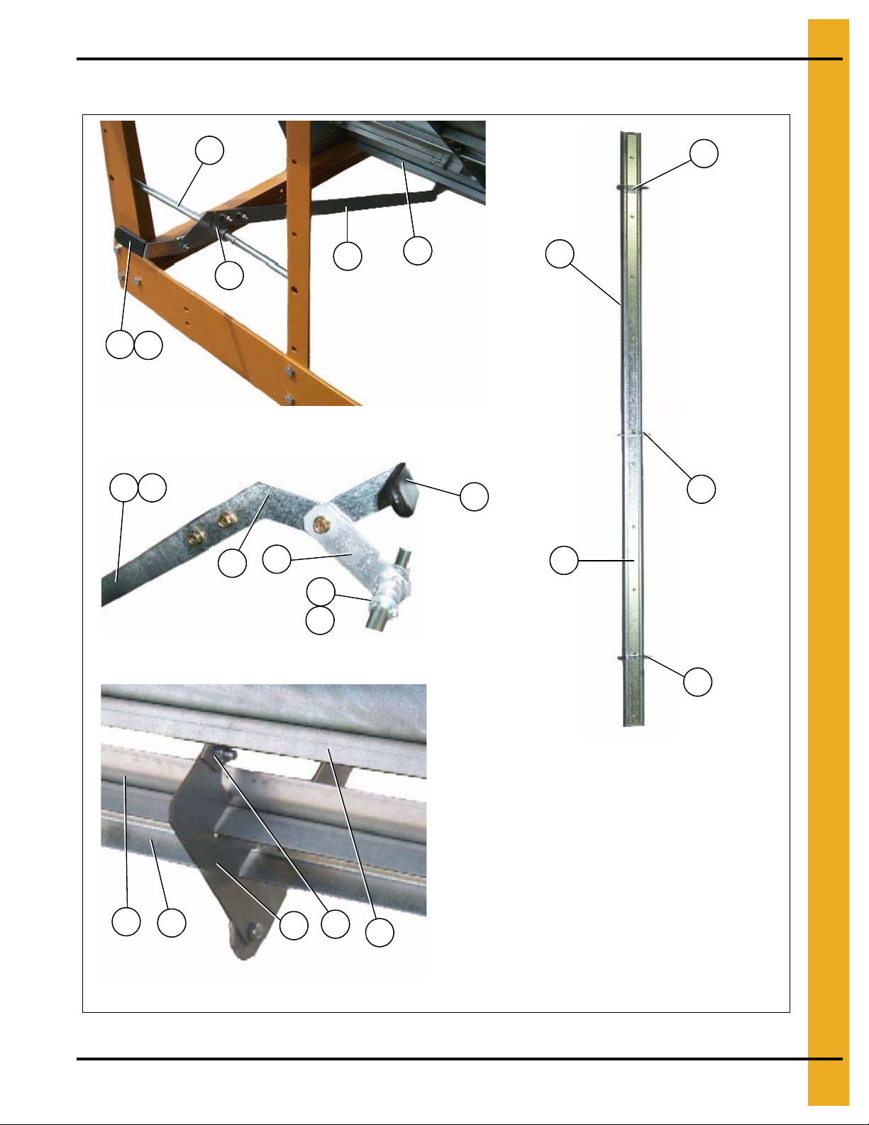
Clean out door hinge
Front and rear handle mechanisms (rear shown in photo)
Clean out door handle mechanism
10
3
1. Bottom Module
PNEG-1404 Vision Series Model 2300 Portable Dryers 15
Figure 1L
Page 16
1. Bottom Module
5
14
1a
14
3a
4
2
14
3a
11
Clean Out Doors (Continued)
Figure 1M Center Handle Mechanisms (This handle mechanism straddles the center cross channels.)
Clean Out Doors Parts List (See Figure 1L and 1M)
Ref # Part # Description
1 D01-0264 Pivot Rod 25-3/16" 2 2 2 2 2
1a D31-0162 Pivot Rod 49-5/8" 1 1 1 2 2
2 D01-0296 Linkage Bar Weldment 4 4 4 6 6
3 D01-0261 Linkage Bar, 37" Long 2 2 2 2 2
3a D01-0293 Linkage Bar, 30" Long 2 2 2 4 4
4 D01-0294 Clean Out Door Handle 4 4 4 6 6
5 S-4378 Plastic Grip 4 4 4 6 6
6 S-248 Flat Washer 3/8" USS ZN 8 8 8 12 12
7 S-7241 Cotter Pin 1/8" x 1-1/4" 8 8 8 12 12
8a D51-0077 Clean Out Door Assembly, 3 Column 1 1
8b D11-0032 Clean Out Door Assembly, 4 Column 1 1 2 2
8c D01-0349 Clean Out Door Assembly, 5 Column 1 2 1
9 D21-0005 Clean Out Door, 67" 1/Assembly
9 D31-0021 Clean Out Door, 91" 1/Assembly
9 D01-0180 Clean Out Door, 115" 1/Assembly
10 D21-0012 Support Channel, Clean Out Door 1/Assembly
10 D31-0130 Support Channel, Clean Out Door 1/Assembly
10 D01-0307 Support Channel, Clean Out Door 1/Assembly
11 D01-0308 Clean Out Door Hinge 2/Assembly
11 D01-0308 Clean Out Door Hinge 2/Assembly
11 D01-0308 Clean Out Door Hinge 3/Assembly
12 D01-0175 Hinge Bracket 4 5 6 6 7
13 D01-0181 Clean Out Extension, 119-3/4" 2 4 2
13 D31-0023 Clean Out Extension, 90-3/4" 2 2 4 4
13 D21-0006 Clean Out Extension, 66-3/4" 2 2
14 D01-0299 Pivot Rod Bracket 3 3 3 6 6
2314 2318 2320 2322 2326
16 PNEG-1404 Vision Series Model 2300 Portable Dryers
Qty
Page 17
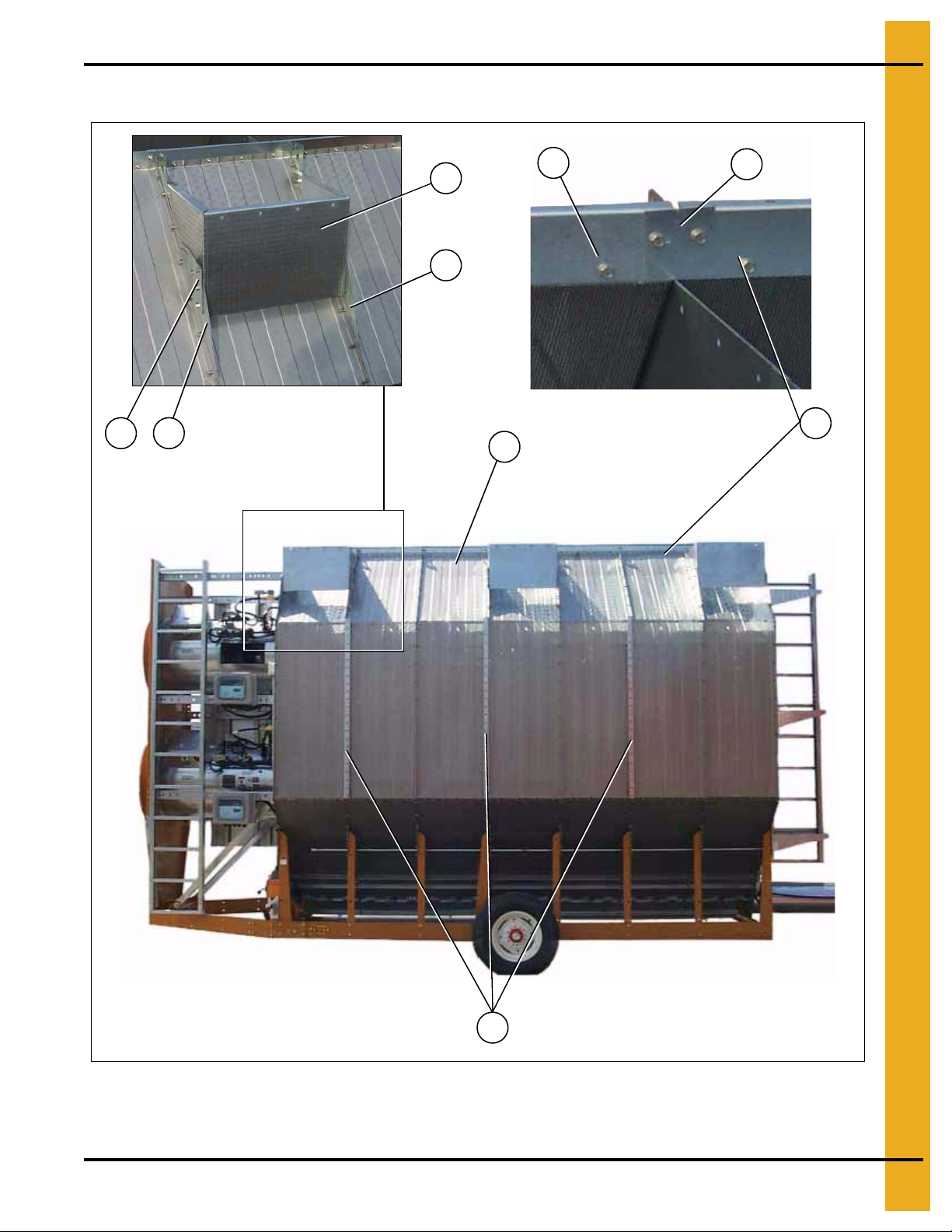
Module Support Pads/Stiffener Attach Angles
2
4
1
8
6
7 5
Top edge angle splice
3
Module support pad
1
1. Bottom Module
Figure 1N
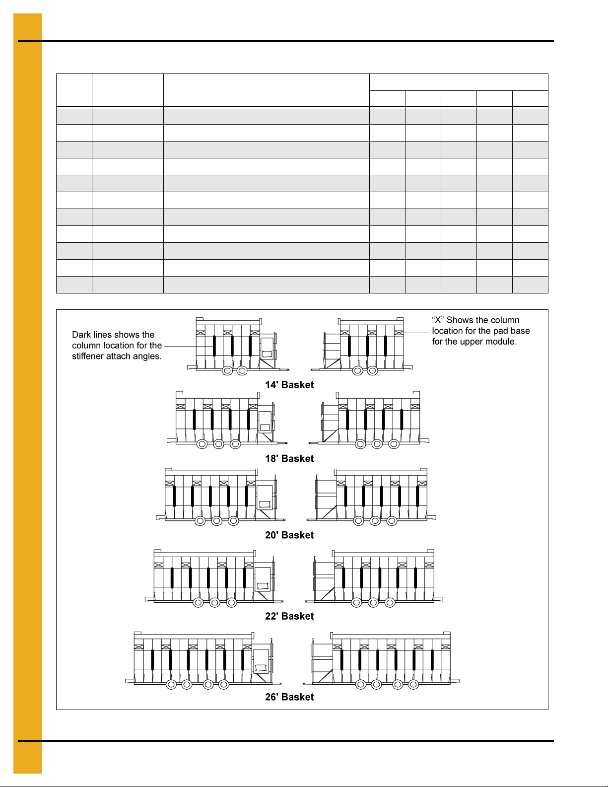
See Page 18 for column locations for the upper module base pads and stiffener attach angles.
PNEG-1404 Vision Series Model 2300 Portable Dryers 17
Page 18
1. Bottom Module
Module Support Pads/Stiffener Attach Angles Parts List (See Figure 1N.)
Ref # Part # Description
2314 2318 2320 2322 2326
1 D21-0003 Top Edge Angle 71-7/8" 2 2
1 D31-0004 Top Edge Angle 95-7/8" 4
1 D01-0168 Top Edge Angle 119-7/8" 2 4
2D31-0003Top Edge Angle Splice 22244
3 D31-0004 Top Edge Angle 95-7/8" 2 2 4
3 D01-0168 Top Edge Angle 119-7/8" 2
4 D01-0872 Stiffener Attach Angle 6 8 10 10 12
5D61-0021Body Tie-In Gusset L.H. 688810
6 D61-0022 Body Tie-In Gusset R.H. 6 8 8 8 10
7D61-0012Crane Bracket 44444
8 D61-0013 Module Support Pad 6 8 8 8 10
Qty
Figure 1O
18 PNEG-1404 Vision Series Model 2300 Portable Dryers
Page 19
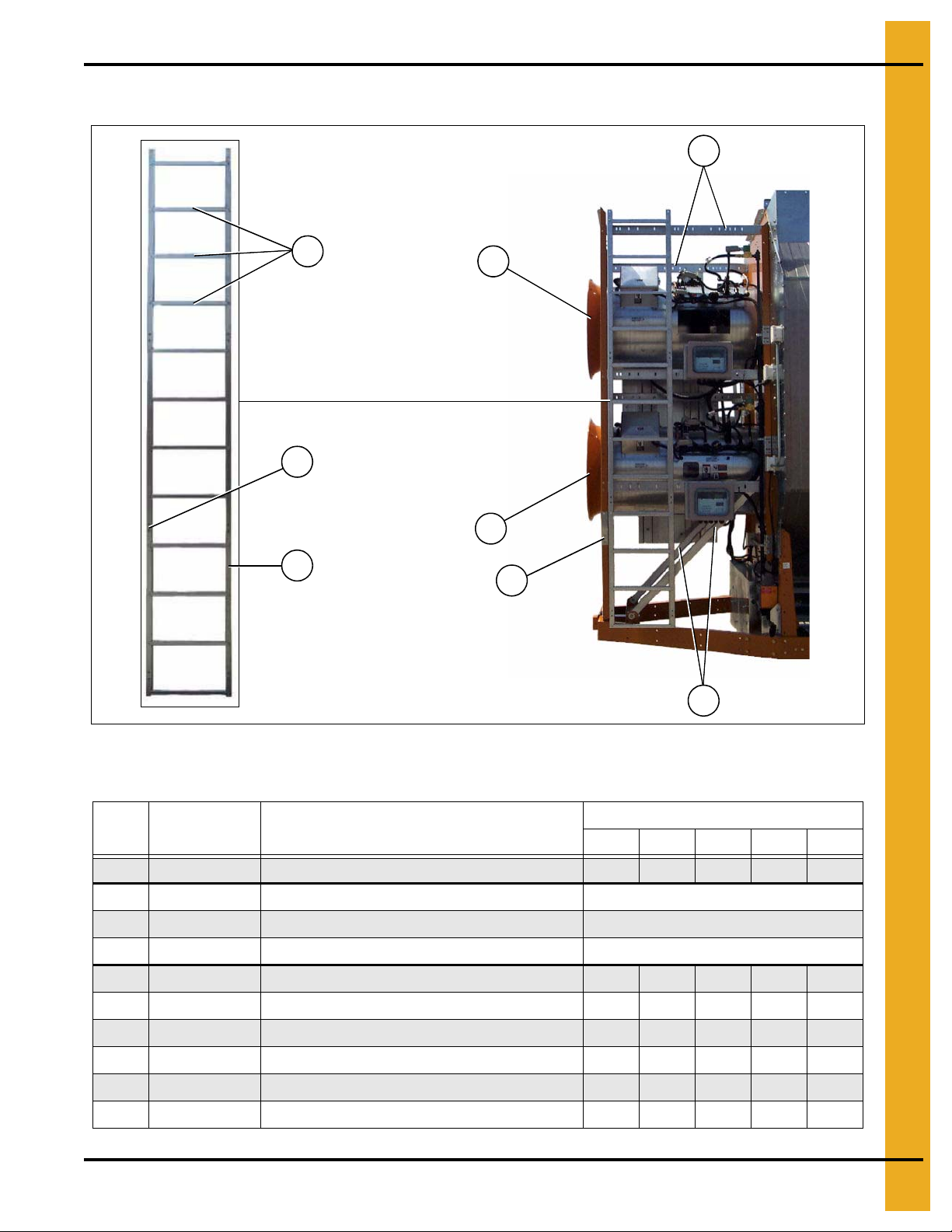
Front Ladder Assembly
5
5
4
6
7
1
2
3
1. Bottom Module
Figure 1P
Front Ladder Assembly Parts List
Ref # Part # Descrip t ion
1-3 D01-1220 Ladder Assembly Stack Dryer Front 1 1 1 1 1
1 D61-0096 Ladder Rung 12/Assembly
2 D61-0094 Ladder Side Rail - L.H. 1/Assembly
3 D61-0095 Ladder Side Rail - R.H. 1/Assembly
4 D51-0022 Support, Control Panel 7 7 7 7 7
5 F-7060-Y Venturi: 28" Yellow/Ochre 2
5 CD-0543-Y Venturi: 36" Ochre 2 2 2
5 CD-0545-Y Venturi: 40" Ochre 2
6 D51-0021 Stiffener, Front Fan Support 2 2 2 2 2
Qty
2314 2318 2320 2322 2326
7 D31-0082 Front Diagonal Support Channel 22222
PNEG-1404 Vision Series Model 2300 Portable Dryers 19
Page 20
1. Bottom Module
4
4
1
2
3
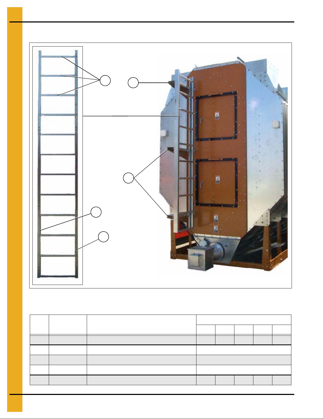
Rear Ladder Assembly
Figure 1Q
Ref # Part # Description
1-3 D04-0388 Ladder Assembly 1 1 1 1 1
1 D61-0096 Ladder Rung 10/Assembly
2 D61-0092 Ladder Side Rail - L.H. 1/Assembly
3 D61-0093 Ladder Side Rail - R.H. 1/Assembly
Rear Ladder Assembly Parts List
Qty
2314 2318 2320 2322 2326
4 D61-0097 Ladder Mounting Bracket, Rear 3 3 3 3 3
20 PNEG-1404 Vision Series Model 2300 Portable Dryers
Page 21
Front End Panels/Fan Support/Grill Guards
5
4
5
3
3
2
1
1. Bottom Module
Figure 1R
Front End Panels/Fan Support/Grill Guards Parts List
Ref # Part # Descrip t ion
1 D61-0023 Top Angle, Fan Support Panel 1 1 1 1 1
2 CD-0576 Grill Guard: CD-28 Black 2
2 CD-0544 Grill Guard: 36" Black 2 2 2
2 CD-0547 Grill Guard: 40" and 42" Black 2
3 D31-0307 Column End Panel 4 4 4 4 4
4 D01-0593 Front Fan Support 2-28" 1
4 D61-0041 Front Fan Support 2-36" 1 1 1
4 D71-0008 Front Fan Support 2-40" 1
5 F-7060-Y Venturi: 28" Yellow/Ochre 2
5 CD-0543-Y Venturi: 36" Ochre 2 2 2
5 CD-0545-Y Venturi: 40" Ochre 2
N/S D01-0594 Front End Panel 2-28" 1
N/S D61-0018 Front End Panel 2-36" 1 1 1
N/S D71-0006 Front End Panel 2-40" 1
2314 2318 2320 2322 2326
Qty
PNEG-1404 Vision Series Model 2300 Portable Dryers 21
Page 22
1. Bottom Module
Rear access door (inside)
3
Rear access door (outside)
5
6
7
8
9
8
1234
1
13
12
5
10
11
6
10
11
Rear End Panels/Rear Access Door
Figure 1S
Rear End Panels/Rear Access Door Parts List
Ref # Part # Description
22 PNEG-1404 Vision Series Model 2300 Portable Dryers
1 D31-0307 Column End Panel 4 4 4 4 4
2 D01-1800-Y Rear End Panel 50/50 29" Doors 11111
3 D01-0044 Top Angle Bracket Front and Rear 3 3 3 3 3
4 D01-1510 Aspirator End Cap 11111
5-13 RDA-29-Y Rear Door Assembly 29" Square Ochre 2 2 2 2 2
5 D01-1783-Y Assist Handle 29" Square Door 2/Assembly
6 D01-1781-Y Door 29" Square Ochre 1/Assembly
7 D03-0512 Door Handle, Locking CCW 1/Assembly
8 D01-1782-BLK Frame Angle 29" Door 4/Assembly
9 DC-973 Decal, Danger Fire Hazard 2/Assembly
10 401-4630-0 Hinge Bracket - Square Door 2/Assembly
11 401-4669-8 Hinge - Rear Access Square Door 2/Assembly
12 D01-0397 Latch Bracket 1/Assembly
13 D01-1792 Latch Bar 29" Square Door 1/Assembly
2314 2318 2320 2322 2326
Qty
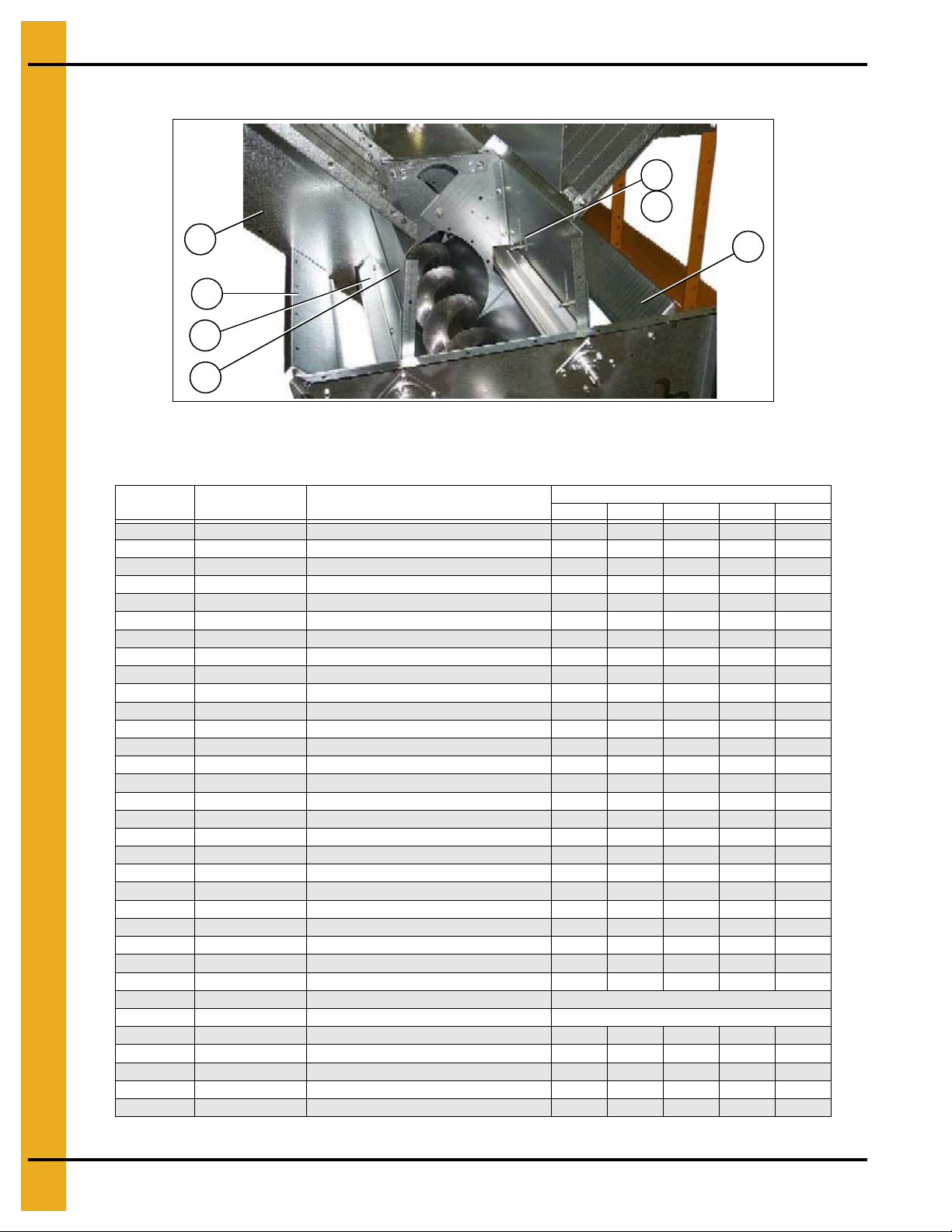
Page 23
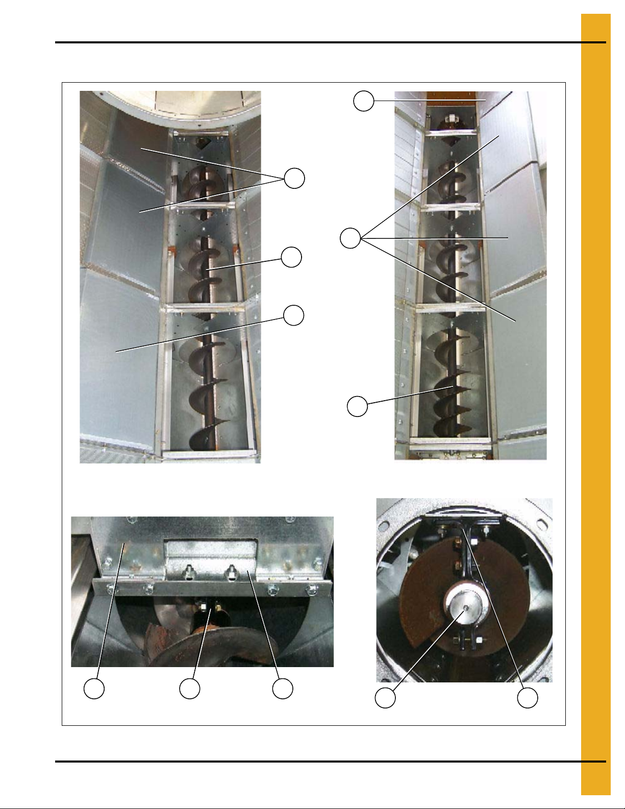
Bottom Auger
2
3
2
4
2
Bottom auger center bearing and support Bottom auger rear bearing
Bottom auger (view from center
of dryer to the forward end)
Bottom auger (view from center
of dryer to the rear end)
5 7 6
8 7
1
1. Bottom Module
Figure 1T
PNEG-1404 Vision Series Model 2300 Portable Dryers 23
Page 24
1. Bottom Module
17
16
15
14
13
12
11
10
9
20
21
Auger bearing
18 19
Rear discharge box
Bottom Auger (Continued)
Bottom Auger Parts List (See Figure 1T and 1U)
Figure 1U
Ref # Part # Description
1 D01-1214 Plenum Closure Door, Rear 1 1 1 1 1
2 D01-1134 Plenum Closure Door 6 8 9 10 12
3 D21-0017 Auger Bottom Front Weldment 1 1
3 D31-0092 Auger Bottom Front Weldment 1 1
3 D31-0092 Auger Bottom Front Weldment (116-3/8" Long) 1
4 D31-0267 Auger Bottom Rear Weldment 1 1 2 2
4 D61-0184 Auger Bottom Rear Weldment (117-7/8" Long) 1
5 D01-1290 Hanger Bearing Bottom “J” Plate 22244
6 D01-1291 Hanger Bearing Bottom “C” Channel 1 1 1 2 2
7 D01-1246 Hanger Bearing Assembly (Short) 22233
8 D31-0076 Shaft, Auger Splice 2 2 2 3 3
9-19 D01-0481-MS Discharge Box Assembly 11111
9 D01-1884 Discharge Weldment 1/Assembly
10 D01-1886 Moisture Sampler Tube Cover Plate 1/Assembly
11 D01-0405 Grain Sampler Assembly 1/Assembly
12 D01-1752 Discharge Side Cover 1/Assembly
13 D01-1751 Discharge Side Panel MC 1/Assembly
14 D31-0298 Discharge Side Panel 1/Assembly
15 D01-1885 Moisture Sampler Cover Plate 1/Assembly
16 D01-1650 Rear Auger Bearing Shield 1/Assembly
17 D31-0299 Discharge Box Bearing Plate 1/Assembly
18 D01-0466 Discharge Top Panel 1/Assembly
19 D01-0467 Discharge Top Flapper 1/Assembly
20 D32-0001 Flangette Bearing 11111
21 D31-0005 Shaft, Top and Bottom Auger Stub 1 1 1 1 1
N/S D31-0079 Discharge Auger Weldment 11111
2314 2318 2320 2322 2326
Qty
24 PNEG-1404 Vision Series Model 2300 Portable Dryers
Page 25
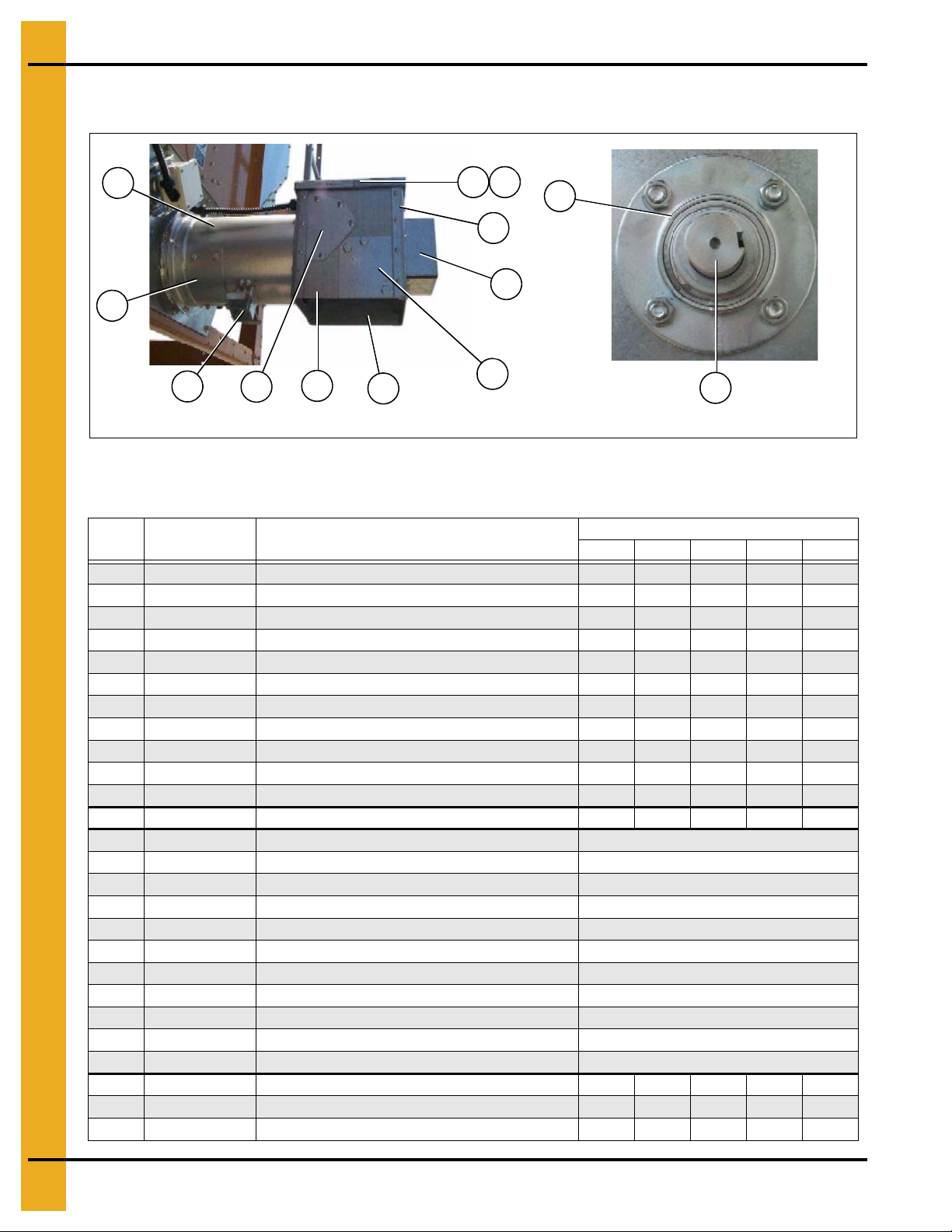
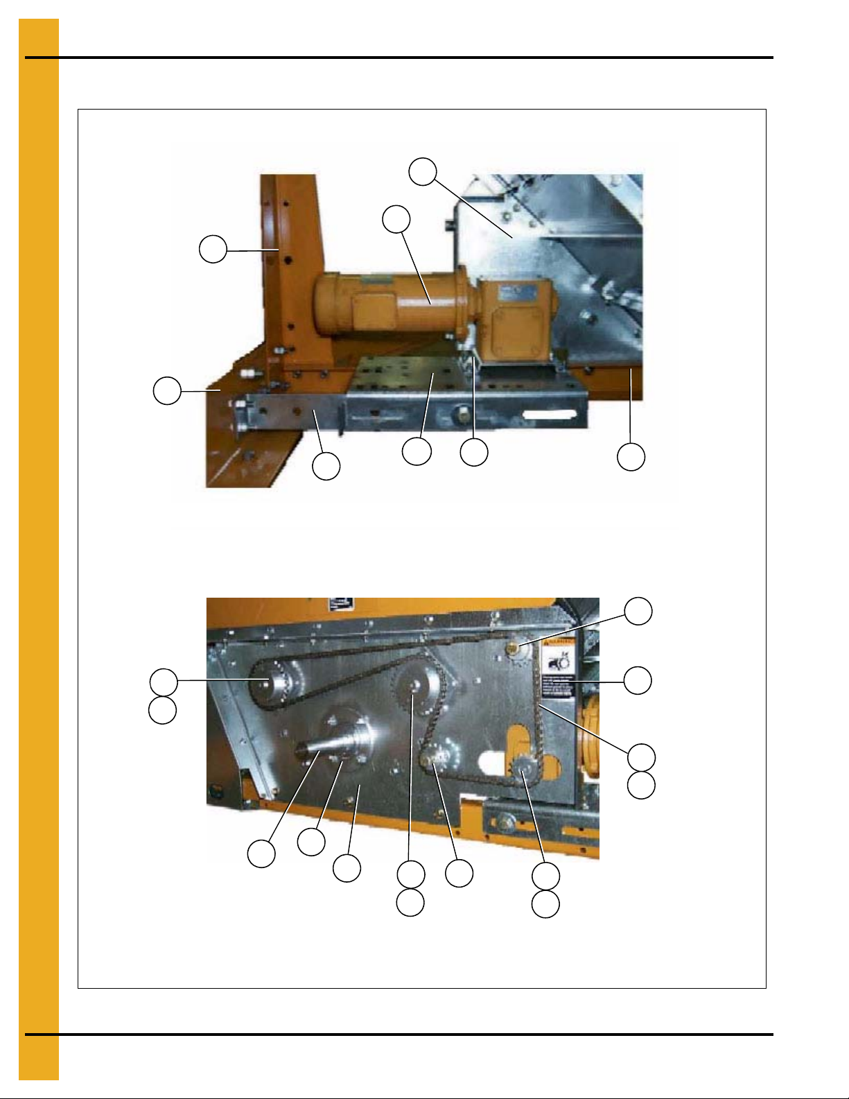
Bottom Auger Drive
1
2
3
4
11
5
9
8
7
6
11
12
13
5
16
6
4
15
14
13
13
18
16
17
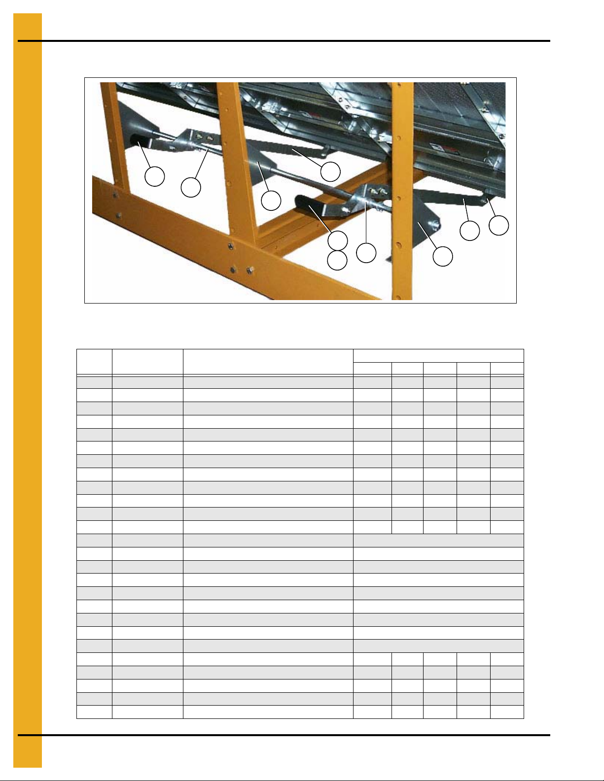
Bottom auger drive components
Bottom auger motor and motor mount
Forward drive tension adjustment
Rear drive tension adjustment
10
1. Bottom Module
Figure 1V
PNEG-1404 Vision Series Model 2300 Portable Dryers 25
Page 26
1. Bottom Module
20
21
19
22
Bottom Auger Drive (Continued)
Figure 1W Bottom Auger and Metering Roll Drive Guard
26 PNEG-1404 Vision Series Model 2300 Portable Dryers
Page 27

Bottom Auger Drive Parts List (See Figure 1V and 1W)
1. Bottom Module
Ref # Part # Description
23142318232023222326
1 D01-1376 Bottom Front Angle Bracket 1 1 1 1 1
2MHC00490V-Belt BX82 22222
3 2818-2 Sheave 2 Grade 3.35D x 1-1/8" 1 1
3 D62-0003 Sheave 2 Grade 4.25D x 1-3/8" 1 1 1
4 D01-0012 Hitch Bracket, Right 1 1 1 1 1
5 D01-1373 Belt Guard, Unload Motor Shroud 11111
6 D01-0029 Hitch Weldment 1 1 1 1 1
7D01-0011 Hitch Bracket, Left 11111
8 D01-2435 Front Bearing Plate 2008 1 1 1 1 1
9 D03-0304 Sheave 2 Grade 20" Gripbelt 11111
10 D32-0019 Bushing Q1 - 1-1/2" Split Taper 1 1 1 1 1
11D01-0065 Spacer, Bearing Shield 22222
*12 500-1 Motor 5 HP 1 PH 1800 RPM 1
12 500-3 Motor 5 HP 3 PH 1800 RPM 1 1
Qty
12 712-3 Motor 7-1/2 HP 3 PH 1800 RPM 1 1
12 1000-3 Motor 10 HP 3 PH 1800 RPM 1
13 D01-0081 Motor Mount - Bottom Auger 1 1 1 1 1
14D01-0008Front and Rear Frame Tie Channel 44466
15 D01-0007 Corner Leg 6 6 6 8 8
16D01-0017Motor Adjustment Bracket 22222
17 D21-0011 Frame Rail, 14' R.H. 1
17 D31-0044 Frame Rail, 18' R.H. 1
17 D61-0002 Frame Rail, 20' R.H. 1
17 D101-0002 Frame Rail, 22' R.H. 1
17 D71-0002 Frame Rail, 26' R.H. 1
18D01-0016Motor Mount Support Bracket 11111
19 D01-1372 Belt Guard, Unload Front Shield 1 1 1 1 1
20PR-331 Peak Cap Handle 22222
21 DC-971 Decal, Belt Drive Warning 2 2 2 2 2
22DC-972 Decal, Chain Warning 22222
* Ref #12, part #500-1 is a 1 phase motor.
PNEG-1404 Vision Series Model 2300 Portable Dryers 27
Page 28
1. Bottom Module
Meter roll drive train components
8
7
1
3
4
2
6
5
15
16
14
9
10
11
8
13
14
12
12
17
9
14
SCR Motor/reduction drive and motor mount assembly
Metering Roll Drive
28 PNEG-1404 Vision Series Model 2300 Portable Dryers
Figure 1X
Page 29
Metering Roll Drive (Continued)
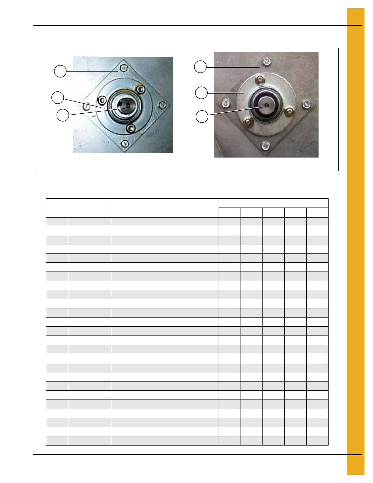
Front meter roll bearing
Rear meter roll bearing
18
18
19
21
19
20
Figure 1Y
Metering Roll Drive Parts List (See Figure 1X and 1Y)
1. Bottom Module
Ref # Part # Description
1 D01-0007 Corner Leg Portable Dryer 6 6 6 8 8
2 D21-0010 Frame Rail, 14' Left 1
2 D31-0043 Frame Rail, 18' Lef t 1
2 D61-0001 Frame Rail, 20' Left 1
2 D101-0001 Frame Rail, 22' Lef t 1
2 D71-0002 Frame Rail, 26' Left 1
3 D01-0016 Motor Mount Support Bracket 1 1 1 1 1
4D01-0081 Motor Mount 11111
5 D01-0704 SCR Motor Gearbox Mount 1 1 1 1 1
6D01-0008 Front and Rear Frame Tie Channel 44466
7 D03-0232 Motor 3/4 HP DC w/ Gearbox 50:1 1 1 1 1 1
8D01-2435 Front Bearing Plate 2008 11111
9 D02-0029 Sprocket 40H30 2 2 2 2 2
10D31-0316Front Bottom Auger Shaft 11111
11 D32-0001 Flangette Bearing 1-1/2" 2 2 2 2 2
12D01-0196Sprocket Idler Assembly 22222
13 D03-0257 Sprocket 4015 x 7/8" Bore w/ Keyway 1 1 1 1 1
14S-9168 Key, Square 1/4" x 1" 33333
15 S-6290 Chain #40 Roller Chain 6' 6' 6' 6' 6'
16D02-0031#40 Chain Connecting Link 11111
17 DC-972 Decal, Chain Warning 2 2 2 2 2
18D01-0003Adaptor Plate 44444
19 GK1583 Flangette Bearing 1", w/ Lock Collar 4 4 4 4 4
20D01-0006Meter Roll Drive Shaft (Front) 22222
21 D01-0272 Meter Roll Shaft Stub (Rear) 2 2 2 2 2
2314 2318 2320 2322 2326
Qty
PNEG-1404 Vision Series Model 2300 Portable Dryers 29
Page 30

2. Top Module
6
7
76
6
76
7
6
3
1 5 2
4 6
Frame/Lower Basket
Figure 2A Front View of the Frame Components
NOTE: The parts pointed out on this page are listed on Page 33.
30 PNEG-1404 Vision Series Model 2300 Portable Dryers
Page 31

Frame/Lower Basket (Continued)
6
76
7
4
6
25
10
1
6
8
9
9
8
2. Top Module
Figure 2B Front View of the Frame/Lower Basket Components
NOTE: The parts pointed out on this page are listed on Page 33.
PNEG-1404 Vision Series Model 2300 Portable Dryers 31
Page 32

2. Top Module
11
10
5
1112
6
8
9
6
9
6
7
6
7
3
Frame/Lower Basket (Continued)
Figure 2C Rear View of the Frame and Lower Basket Components
32 PNEG-1404 Vision Series Model 2300 Portable Dryers
Page 33

Frame/Lower Basket (Continued)
8
9
7
1
4
1
0
1
3
5
1
3
1
4
7
9
8
2. Top Module
Figure 2D
Frame/Lower Basket Parts List (See Figure 2A, 2B, 2C and 2D.)
Ref # Part # Description
1 D01-0012 Hitch Bracket Right 1 1 1 1 1
2D01-0011Hitch Bracket Left 11111
3 D21-0011 Frame Rail, 14' Right 1
3 D31-0044 Frame Rail, 18' Right 1
3 D61-0002 Frame Rail, 20' Right 1
3 D101-0002 Frame Rail, 22' Right 1
3 D71-0001 Frame Rail, 26' Right 1
4 D21-0010 Frame Rail, 14 ' Left 1
4 D31-0043 Frame Rail, 18' Left 1
4 D61-0001 Frame Rail, 20 ' Left 1
4 D101-0001 Frame Rail, 22' Left 1
4 D71-0002 Frame Rail, 26 ' Left 1
5 D61-0048 Frame Tie Channel 2 2 2 2 2
6D01-0007Corner Leg Portable Dryer 66688
7 D01-0005 Side Leg Portable Dryer 10 14 16 16 20
8 D01-0004 Gusset Plate 16 20 22 24 28
9 D01-0101 Garner Bulkhead 24 32 36 40 48
10 D61-0077 Connecting Section End 22222
11 D61-0017 Screen, Connectin g - Inner, Gauge, 094 14 18 20 22 26
12 D61-0103P Connecting Bulkhead Extension 12 16 18 20 24
13 D61-0073 Screen, Connecting - Outer, Gauge, 094 14 18 20 22 24
14 D61-0019 Module Tie Brace 6 8 10 10 12
2314 2318 2320 2322 2326
Qty
PNEG-1404 Vision Series Model 2300 Portable Dryers 33
Page 34

2. Top Module
4
5
6
7
8
9
1
0
3
2
1
4
a
4
*
Inside (Plenum) Screens/Outside Screens
Figure 2E
* NOTE: Ref #4 is pointing to the top edge angle gusset. There are two (2) types of gusset on the dryer.
The photo left will help distinguish the difference between the two (2). The arrows are pointing to
a tab on the gusset that makes them different (tabs are “bent” up in photo). Ref #4a is used in
two (2) places only; 1) front right of dryer, 2) rear left of dryer, all others are Ref #4.
Inside (Plenum) Screens/Outside Screens Parts List
Ref # Part # Description
1 D01-0126 Screen, Plenum Top, Gauge, 094 14 18 20 22 26
2 D31-0012 Screen, Plenum Wall, Gauge, 094 14 18 20 22 26
3 D01-0124 Screen, Plenum Bottom, Gauge, 094 14 18 20 22 26
4 D01-0152 L.H. Top Angle Gusset 12 16 18 20 24
4a D01-0153 R.H. Top Angle Gusset 2 2 2 2 2
5 D01-0127 Screen, Roof, Gauge, 094 14 18 20 22 26
6 D31-0013 Screen, Outside Wall, Gauge, 094 14 18 20 22 26
7 D01-0128 Screen, Hopper, Gauge, 094 14 18 20 22 26
8 D61-0019 Module Tie Brace 6 8 10 10 12
9 D61-0073 Screen, Connecting - Outer, Gauge, 094 14 18 20 22 24
10 D31-0307 Column End Panel 4 4 4 4 4
2314 2318 2320 2322 2326
Qty
34 PNEG-1404 Vision Series Model 2300 Portable Dryers
Page 35

Stiffener Attach Angles/Crane Brackets
1
2
1
3
2. Top Module
Figure 2F
See Page 18 for the locations of the stiffener attach angle.
Stiffener Attach Angles/Crane Brackets Parts List
Ref # Part # Description
1 D61-0015 Top Module Crane Bracket 4 4 4 4 4
2D61-0014Hoisting Spreader Bar 22222
3 D01-0872 Stiffener Attach Angle 6 8 10 10 12
PNEG-1404 Vision Series Model 2300 Portable Dryers 35
2314 2318 2320 2322 2326
Qty
Page 36

2. Top Module
4
3
2
1
Fan support extension attach angles
Service platform attach bracket
2
1
1
4
6
5
a
5
7
101
1
1
2
1
3
8
9
1
0
Front End Panels/Fan Support/Grill Guard and Venturi
Figure 2G
Front End Panels/Fan Support/Grill Guard and Venturi Parts List
Ref # Part # Description
1 D61-0023 Top Angle, Fan Support Panel 2 2 2 2 2
2 D61-0306 Fan Support Extension, 42" Fans 1 1 1 1 1
3 D61-0307 Top Angle (Notched) Fan Support Panel 1 1 1 1 1
4 D01-1829 Stiffener, Fan Support Extension 2 2 2 2 2
5 CD-0547 Grill Guard: 40" and 42" Black 1 1 1 1 1
5a CD-0545-Y Venturi, 40" 1
5a CD-0546-Y Venturi, 42" 1 1 1 1
6 D31-0307 Column End Panel 4 4 4 4 4
7 D01-1458 Front Fan Supp ort, 1-40" 1
7 D51-0132 Front Fan Support, 1-42" 1 1 1 1
8 D01-0011 Hitch Bracket, L.H. 1 1 1 1 1
8 D01-0012 Hitch Bracket, R.H. 1 1 1 1 1
9 D61-0054 Platform Attach Bracket 2 2 2 2 2
10 D01-0029 Hitch Weldment 1 1 1 1 1
11 D51-0022 Support, Control Panel 6 6 6 6 6
12 D01-0062 Front Diagonal Support Channel 2 2 2 2 2
13 D51-0021 Stiffener, Front Fan Support 2 2 2 2 2
14 D01-1459 Front End Panel, 1-40" 1
14 D51-0131 Front End Panel, 1-42" 1 1 1 1
2314 2318 2320 2322 2326
Qty
36 PNEG-1404 Vision Series Model 2300 Portable Dryers
Page 37

2. Top Module
7
8
9
1
0
1
0
1
1
7
1
4
1
5
1
3
1
2
8
1
3
1
2
Rear access door (outside) Rear access door (inside)
2
1
2
3
4
6
5
NOTE: The ladder assembly shown above is the same for the front and rear on upper modules.
Rear End Panels/Rear Access Door/Front and Rear Ladders
Figure 2H
PNEG-1404 Vision Series Model 2300 Portable Dryers 37
Page 38

2. Top Module
Rear End Panels/Rear Access Door/Front and Rear Ladders Parts List (See Figure 2H.)
Ref # Part # Description
2314 2318 2320 2322 2326
1 D01-1780-Y Rear End Panel 1 1 1 1 1
2D31-0307Column End Panel 44444
3 D61-0097 Ladder Mounting Bracket, Rear 3 3 3 3 3
4-6 D0 1-1220 Ladder Assembly Stack Dryer Front 11111
4 D61-0096 Ladder Rung 12/Assembly
5 D61-0094 Ladder Side Rail - L.H. 1/Assembly
6 D61-0095 Ladder Side Rail - R.H. 1/Assembly
7-15RDA-29-YRear Door Assembly 29" Square Ochre 11111
7 D01-1783-Y Assist Handle 29" Square Door 2/Assembly
8 D01-1781-Y Door 29" Square Ochre 1/Assembly
9 D03-0512 Door Handle, Locking CCW 1/Assembly
10 D01-1782-BLK Frame Angle 29" Door 4/Assembly
11 DC-973 Decal, Danger Fire Hazard 2/Assembly
12 401-4630-0 Hinge Bracket - Square Door 2/Assembly
Qty
13 401-4669-8 Hinge - Rear Access Square Door 2/Assembly
14 D01-0397 Latch Bracket 1/Assembly
15 D01-1792 Latch Bar 29" Square Door 1/Assembly
38 PNEG-1404 Vision Series Model 2300 Portable Dryers
Page 39

Top Auger with Wet Bin Assembly
Top auger with wet bin (switch paddle end)
1
1
2
3
4
6
5
7
8
9
3
1
13
14a
14
Top auger (fill end)
10
11
12
8
9
5
2. Top Module
PNEG-1404 Vision Series Model 2300 Portable Dryers 39
Figure 2I
Page 40

2. Top Module
Top auger bearing support
Top auger bearing support (inside view)
15
16
17
10
21
22
18
19
20
22
21
7
7
23
16
24 25
Top Auger with Wet Bin Assembly (Continued)
Figure 2J
NOTE: The parts pointed out on this page are listed on Page 41.
40 PNEG-1404 Vision Series Model 2300 Portable Dryers
Page 41

Top Auger with Wet Bin Assembly Parts List (See Figure 2I and 2J.)
2. Top Module
Ref # Part # Description
2314 2318 2320 2322 2326
1 D01-1521 Wet Bin Side, 4' Side Galvanized Perfed 4 4 2 4
1 D01-1522 Wet Bin Side, 6' Side Galvanized Perfed 2 6 4 6 6
2 D01-0103 Mercury Switch Shaft 1 1 1 1 1
3 D21-0003 Top Edge Ang l e 71 -7 /8" 2 2
3 D31-0004 Top Edge Ang l e 95 -7 /8" 2 2 4 4
3 D01-0168 Top Edge Angle 119-7/8" 2 4 2
3a D31-0003 Top Ed ge Ang l e Splice 2 2 2 4 4
5 D01-0147 Top Auger Housing Hinge L.H. 2 2 2 2 2
6 D01-0167 Mercury Switch Paddle Weldment 1 1 1 1 1
7 D21-0015 Auger Top Front Weldment 1 1
7 D31-0091 Auger Top Front Weldment 1 1 1
7 D31-0267 Auger Top and Bottom Weldment 1 1 2 2
7 D61-0184 Auger Weldment 117-7/8" 1
8 D01-0148 Top Auger Housing Hinge R.H. 2 2 2 2 2
9 D01-1525 Wet Bin End 2 2 2 2 2
10 D21-0002 Top Au ge r Trough Side/6' 2 2
10 D31-0010 Top Au ge r Trough Side/8' 2 2 4 4
10 D01-0161 Top Au ge r Trough Side/10' 2 4 2
11 D01-1650 Rear Auger Bearing Cover 1 1 1 1 1
12 D31-0028 Top Auger Housing End 2 2 2 2 2
13 D32-0001 Bearing 1-1/2" Diameter w/ Flangette 2 2 2 2 2
14 D31-0090 Shaft, Top Auger Front 1 1 1 1 1
14a D31-0005 Shaft, Top Auger Stub Rear 1 1 1 1 1
15 D01-1123 Top Auger Cover, 30-1/4" 1 1 1 1 1
15 D01-1124 Top Auger Cover, 24-1/4" 3 5 7 5 7
15 D01-1125 Top Auger Cover, 20-1/4" 2 2 2 4 4
16 D31-0015 Top Auger Bearing Support 1 1 1 2 2
17 D31-0011 Center Stabilizer Beam 1 1 1 2 2
18 D31-0009 Gusset Attach Bracket 2 2 2 4 4
19 D31-0001 Center Handrail Gusset L.H. 2 2 2 4 4
20 D31-0002 Center Handrail Gusset R.H. 2 2 2 4 4
21 D21-0001-Y Handrail Support, 1" EMT x 71-3/4" 2 2
21 D31-0006-Y Handrail Support, 1" EMT x 95-3/4" 2 2 4 4
21 D01-0151-Y Handrail, 1" EMT x 119-3/4" Long 2 4 2
22 D01-0140 Hanger Bracket - Handrail Galvanized 16 16 16 24 24
23 D31-0008 Top Au ge r Trough Splice 2 2 2 4 4
24 D01-1245 Top Auger Bearing Hanger Assembly 1 1 1 1 1
25 D31-0076 Shaft, Auger Splice 1 1 1 2 2
Qty
PNEG-1404 Vision Series Model 2300 Portable Dryers 41
Page 42

2. Top Module
Top auger belt guard cover
Top auger drive components
1
2
3
14
4
5
12
13
Belt guard upper mount
1
6
Top Auger Drive
Figure 2K
42 PNEG-1404 Vision Series Model 2300 Portable Dryers
Page 43

Top Auger Drive (Continued)
7
8
9
10
11
2. Top Module
Figure 2L Top Auger Motor and Motor Mount
Top Auger Drive Parts List (See Figure 2K and 2L.)
Ref # Part # Description
1 D01-0453 Top Auger Belt Guard Body 1 1 1 1 1
2 D52-0001 Sheave 2 Grade 16" Gripbelt 1 1 1 1 1
3 D32-0019 Bushing Q1 - 1-1/2" Split Taper 1 1 1 1 1
4 D01-0464 V-Belt BX97 2 2 2 2 2
5 2818-2 Sheave 2 Grade 3.35D x 1-1/8" Bore 1 1
5 D62-0003 Sheave 2 Grade 4.25D x 1-3/8" 1 1 1
6 D01-0155 Mounting Bracket - Belt Guard Spacer 1 1 1 1 1
7 D01-0424 Dryer Top Hand Hold 1 1 1 1 1
*8 500-1 Motor 5 HP 1 PH 1800 RPM 1
8 500-3 Motor 5 HP 3 PH 1800 RPM 1 1
8 712-3 Motor 7-1/2 HP 3 PH 1800 RPM 1 1
8 1000-3 Motor 10 HP 3 PH 1800 RPM 1
9 D01-0173 Top Motor Mount Weldment 1 1 1 1 1
10 D01-0465 Turnbuckle 1/2" x 6" Plated 1 1 1 1 1
11 D01-0170 Anchor Bracket - Motor Mount 1 1 1 1 1
12 D01-0452-Y Top Auger Belt Guard Cover Ochre 1 1 1 1 1
13 DC-971 Decal, Belt Drive Warning 2 2 2 2 2
14 FH-4429-1 Latch 3 3 3 3 3
*Ref #8, Part #500-1 is a 1 phase motor.
2314 2318 2320 2322 2326
Qty
PNEG-1404 Vision Series Model 2300 Portable Dryers 43
Page 44

3. Fan/Heaters
36" and 42" Burner support and collector cup
1
3
10a
9a
Fan/Heater housing assembly
4
5
8
7
6
2
26" and 28" Burner support and collector cup
9
10
Fan/Heater Housing Assembly
Figure 3A
44 PNEG-1404 Vision Series Model 2300 Portable Dryers
Page 45

Fan/Heater Housing Assembly Parts List (See Figure 3A.)
3. Fan/Heaters
Ref # Part # Description
28" 36" 40" 42"
1 D01-1996 Wrapper, 28" Fan/Heater 1
1 D01-1963 Wrapper, 36" Fan/Heater 1
1 D01-1997 Wrapper, 40" Fan/Heater 1
1 D01-1964 Wrapper, 42" Fan/Heater 1
2 D01-0529 Straightening Vane, 28" Fan/Heater 11
2 D01-1452 Straightening Vane, 36"-42" Fan/Heater 11 11 11
3 D01-0528 Inner Can, 28" Fan/Heater 1
3 D01-1480 Inner Can, 36" Fan/Heater 1
3 D01-1479 Inner Can, 40" Fan/Heater 1
3 D01-1451 Inner Can, 42" Fan/Heater 1
4 401-5759-6-B Access Door - Galvanized Fan Black 1 1 1 1
5 069-1303-2 Sight Glass 1111
6 DC-1224 Decal, Danger High Voltage 1 1 1 1
7DC-1225 Decal, Warning Rotating Blade 1111
Qty
8 DC-1227 Decal, Warning Fire 1 1 1 1
9 HF-983 Collector Cup, 28" Fan/Heater 1
9a D01-1484 Collector Cup, 36" Fan/Heater 1
9a D01-1485 Collector Cup, 40" Fan/Heater 1
9a TF-1217 Collector Cup, 42" Fan/Heater 1
10 HF-7092 Support Plate, 28" Fan/Heater 1
10a D01-1482 Support Bracket, 36" Fan/Heater 1
10a D01-1483 Support Bracket, 40" Fan/Heater 1
10a TF-1216 Support Bracket, 42" Fan/Heater 1
PNEG-1404 Vision Series Model 2300 Portable Dryers 45
Page 46

3. Fan/Heaters
Fan blade and bushing
Fan motor and motor mount
1
2
3
4
Matching the right size fan/heater to the model number of the dryer.
Figure 3B
Fan Motor/Motor Mount/Fan Blade
Figure 3C
46 PNEG-1404 Vision Series Model 2300 Portable Dryers
Page 47

Fan Motor/Motor Mount/Fan Blade Parts List (See Figure 3C.)
3. Fan/Heaters
Fan/Heater
(Diameter up)
28'' 12 HP
36'' 12 HP
36'' 15 HP
40'' 15 HP
40'' 25 HP
42'' 20 HP
42'' 25 HP
42'' 30 HP
42'' 40 HP
Ref #
220V 1 PH 208V 3 PH 220V 3 PH 440V 3 PH 575V 1 PH
1 D01-0530 D01-0530 D01-0530 D01-0530 D01-0530 Motor Mount
2 CD-0110 CD-0239 CD-0239 CD-0239 D03-0193 Motor
3 D03-0302 D03-0302 D03-0302 D03-0302 D03-0302 Fan Blade
4 PT0778 PT0778 PT0778 PT0778 PT0778 Bushing
1 D01-1478 D01-1478 D01-1478 D01-1478 D01-1478 Motor Mount
N/S CD-0233 CD-0233 CD-0233 CD-0233 CD-0233 Motor Mount Adapter
2 CD-01 10 CD-0239 CD-0239 CD-0239 CH-6819 Motor
3 D01-0468 D01-0468 D01-0468 D01-0468 D01-0468 Fan Blade
4 FH-1009 FH-1009 FH-1009 FH-1009 FH-1009 Bushing
1 D01-1478 D01-1478 D01-1478 D01-1478 D01-1478 Motor Mount
2 002-1073-2 CH-1050 CH-1050 CH-1050 CH-6820 Motor
3 D82-0002 D82-0002 D82-0002 D82-0002 D82-0002 Fan Blade
4 FH-1009 FH-6963 FH-6963 FH-6963 FH-6963 Bushing
1 D01-1481 D01-1481 D01-1481 D01-1481 D01-1481 Motor Mount
2 CD-0571 CH-1050 CH-1050 CH-1050 CH-6820 Motor
3 D03-0567 D03-0567 D03-0567 D03-0567 D03-0567 Fan Blade
4 GC03810 GC03810 GC03810 GC03810 GC03810 Bushing
1 N/A D01-1477 D01-1477 D01-1477 D01-1477 Motor Mount
2 N/A C-2049 C-2049 C-2049 CH-6692 Motor
3 N/A D72-0003 D72-0003 D72-0003 D72-0003 Fan Blade
4 N/A CE-00617 CE-00617 CE-00617 CE-00617 Bushing
1 N/A D01-1453 D01-1453 D01-1453 D01-1453 Motor Mount
2 N/A CH-1051 CH-1051 CH-1051 2000-3-5 Motor
3 N/A D01-0470 D01-0470 D01-0470 D01-0470 Fan Blade
4 N/A GC03810 GC03810 GC03810 GC03810 Bushing
1 N/A D01-1474 D01-1474 D01-1474 D01-1474 Motor Mount
2 N/A C-2049 C-2049 C-2049 CH-6692 Motor
3 N/A D01-0471 D01-0471 D01-0471 D01-0471 Fan Blade
4 N/A CE-00617 CE-00617 CE-00617 CE-00617 Bushing
1 N/A D01-1474 D01-1474 D01-1474 D01-1474 Motor Mount
2 N/A TFH-2011 TFH-201 1 TFH-2011 CH-6917 Motor
3 N/A D01-0471 D01-0471 D01-0471 D01-0471 Fan Blade
4 N/A CE-00617 CE-00617 CE-00617 CE-00617 Bushing
1 N/A D01-1474 D01-1474 D01-1474 D01-1474 Motor Mount
2 N/A CH-6848 CH-6848 CH-6848 CH-6887 Motor
3 N/A D01-0471 D01-0471 D01-0471 D01-0471 Fan Blade
4 N/A CE-00617 CE-00617 CE-00617 CE-00617 Bushing
Part #
Description
PNEG-1404 Vision Series Model 2300 Portable Dryers 47
Page 48

3. Fan/Heaters
2
1a
1
Air Mixer Assemblies
Figure 3D Air Mixer Assemblies (36'' Air mixer shown in photo)
Air Mixer Assemblies Parts List
Ref # Part # Description
28'' F/H 36'' F/H 40'' F/H 42'' F/H
1-2 D01-0955 Air Mixer Assembly, 28" 1
1-2 CD-0113 Air Mixer Assembly, 36" 1
1-2 CD-0117 Air Mixer Assembly, 40" 1
1-2 CD-0118 Air Mixer Assembly, 42" 1
1 D01-0951 Air Mixer Can, 28" x 15" Long 1/Assembly
2 CD-0228 Small Diameter Can Air Mixer Vane 6/Assembly
2 CD-0083 Air Mixer Vane 8/Assembly
1a D01-0950 Air Mixer Can, 28" x 8" Short 1/Assembly
1 and 1a D01-1303 Air Mixer Can, 36" w/ Access 2/Assembly
1 and 1a D01-1218 Air Mixer Can, 40" w/ Access 2/Assembly
1 and 1a CD-0192 Air Mixer Can, 42" 2/Assembly
Qty
48 PNEG-1404 Vision Series Model 2300 Portable Dryers
Page 49

Flame Probe/Ignitor/Burner Assemblies
9
10
Ref #9 and 10 are used in LP fan/heaters only.
Ignitor
4
6
7
8
5
3
1
2
Flame probe
Ignitor and flame probe assemblies
3. Fan/Heaters
Figure 3E
Flame Probe/Ignitor/Burner Assemblies Parts List
Ref # Part # Description
2612 2812 3615 4015 4220 4225 4230 4240
10 CD-0414 Vaporizer Coil 26"-28'' 3 Wrap 1 1
10 HF-7207 Vaporizer Coil 36"-42'' 10-17 HP 1 1 1
10 HF-7251 Vaporizer 3/4'' 3 Wrap 36-42'' 1 1
10 HF-7319 Vapor Coil (Spiral) 42'' 40 HP 1
PNEG-1404 Vision Series Model 2300 Portable Dryers 49
Qty
Page 50

Burner housing high-limit switch
28'' Fan/Heater burner assembly
26" Fan/Heater burner assembly
14
15
12
11
13
16 17 18 19 22 20 21
3. Fan/Heaters
Flame Probe/Ignitor/Burner Assemblies (Continued)
50 PNEG-1404 Vision Series Model 2300 Portable Dryers
Figure 3F
Page 51

Flame Probe/Ignitor/Burner Assemblies (Continued)
36" Fan/Heater burner assembly
40'' and 42" Fan/Heater burner assembly
26
27
25
24
23
28
29
30
31
3. Fan/Heaters
PNEG-1404 Vision Series Model 2300 Portable Dryers 51
Figure 3G
Page 52

3. Fan/Heaters
Flame Probe/Ignitor/Burner Assemblies Parts List (See Figure 3E, 3F and 3G.)
Qty
Ref # Part # Description
1-3 TF-1559-N Flame Probe Assembly Network 1 1 1 1 1
1 HH-7025 Boot 8 mm Silicone 90° 1/Assembly
2 THH-4179 Flame Sensor 6" Long Rod 1/Assembly
3 CD-0187 Flame Sensor Bracket 1/Assembly
4-8 TF-1558 Ignitor Assembly 1 1 1 1 1
4 HF-7204 Dual Probe Ignitor Bracket 1/Assembly
5 D01-0878 Ignitor Air Deflector Angle 1/Assembly
6 HF-7201 Ignitor Half Clamp 2/Assembly
7 CD-0238 Ignitor Flame 2/Assembly
8 TF-1867 Ignition Wire Assembly (Includes Both Wires) 1/Assembly
9 HH-7054 Cone 26”/28" Burner S.S. 1 1
9 HH-7056 Cone 36”/42" Burner S.S. 1 1 1
10 See Chart on Page 49
11 THH-4064 Unilet Type LRL Conduit Box 1/2" 1 1 1 1 1
12 027-1006-9 Thermostat - High-Limit 200F Auto 1 1 1 1 1
13 D01-1473 Housing High-Limit Plate 1 1 1 1 1
14 No Number Lid for LRL Conduit Box is Part of Ref #11 N/A
15 TFC-0076 Neoprene Gasket, Conduit Body 1 1 1 1 1
16-18 BA-26 26" Burner Assembly 1
16 HF-992 26" Diverter Weldment 1/Assembly
17 HH-3934 Burner Gun Machined 26" 1/Assembly
18 HH-1179 Flame Spreader 26" 1/Assembly
19-22 BA-28 28" Burner Assembly 1
19 HF-7629 Diverter Weldment 28" 1/Assembly
20 THF-3144 Flame Spreader 28" 1/Assembly
21 THF-3141 Heater Gun Machined 28" 1/Assembly
22 THF-3113 28" Diverter Bracket 1/Assembly
23-27 BA-36 36" Burner Assembly 1
23 THF-3038 Diverter Bracket 36" and 40" 3/Assembly
24 THF-3038P Diverter Bracket 36" and 40" Perfed 4/Assembly
25 THF-3039 Diverter Bracket 36" and 40" w/ Hole 1/Assembly
26 THF-3057 Flame Spreader 36"-42" 1/Assembly
27 CD-0091 Burner Weldment CD 36" and 40" 1/Assembly
28-31 BA-40-2 40" Burner Assembly 1
28 CD-0448P Diverter Bracket 42" Perfed 4/Assembly
29 CD-0448 Diverter Bracket 42" 4/Assembly
30 CD-0208 Burner Weldment CD 42" 1/Assembly
31 THF-3057 Flame Spreader 36"-42" 1/Assembly
28-31 BA-42 42" Burner Assembly 1
28 CD-0448P Diverter Bracket 42" Perfed 4/Assembly
29 CD-0448 Diverter Bracket 42" 4/Assembly
30 CD-0208 Burner Weldment CD 42" 1/Assembly
31 THF-3057 Flame Spreader 36"-42" 1/Assembly
26'' F/H28'' F/H36'' F/H40'' F/H42'' F/
H
52 PNEG-1404 Vision Series Model 2300 Portable Dryers
Page 53

LP Pipe Train Assemblies
28" Vaporizer coil connection and adjustment brackets
18
2
3
4
7
8
10
4
9
11
2
14
15
16
22
21
28
29
27
12
13
12
28" Fan/Heater LP pipe train assembly
25 26
24
1
5
6
17
19
17
20
23
24
3. Fan/Heaters
Figure 3H
PNEG-1404 Vision Series Model 2300 Portable Dryers 53
Page 54

3. Fan/Heaters
28" Fan/Heater LP Pipe Train Assemblies Parts List (See Figure 3H.)
Ref # Part # Description 28" Fan
1 THH-4120 Elbow, 3/4" - 90° SCH 40 1
2 THH-4121 Nipple, 3/4" Close SCH 40 2
3 007-1048-3 Ball Valve, 3/4" w/ Lever Handle 1
4 THH-4125 Nipple, 3/4" x 2" SCH 40 2
5 THH-4154 Tee, 3/4" x 3/4" x 1/4" SCH 40 1
6 HH-2984 Gauge, Pressure 0-30# LP 1
7 THH-4136 Nipple, 3/4" x 3" SCH 40 1
8 056-2223-8 Valve, Solenoid 3/4" NPT 115V Din 1
9 056-2228-7 Valve, Solenoid 3/4" NPT 115V Bypass 1
10 THH-4066 Elbow, 3/4" - 90° Street SCH 40 1
11 THH-4149 Elbow, 3/4"-1/2" - 90° Reducer SCH 40 1
12 HH-2029 Nipple, 1/2" x 1-1/2" SCH 40 2
13 HH-1453 Tee, 1/2" x 1/2" x 1/2" SCH 40 1
14 HH-7013 Switch Screw-In Vapor High-Limit 1
15 THH-4071 Elbow, 1/2" - 90° SCH 40 1
16 TFC-0023-50 Regulator, 1/2" NPT 50 PSI 1
17 D07-0019 Nipple, 1/2" x 1-1/2" SCH 80 2
18 031-1008-7 Pressure Relief Valve 300 PSI 1
19 HH-4846 Tee, 1/2" x 1/2" x 1/4" SCH 80 1
20 HH-1251 Strainer, 1/2" “Y” SCH 80 1
21 HH-1932 Elbow, 1/2" - 90° Pipe - 1/2" Flare Brass 1
22 TFC-0095 Hose, 1/2" x 24" LP Gas 2
23 TF-1227 Pipe Train Bracket for 36" and 42" 1
24 326-1047-9 U-Bolt 5/16"-18 x 1-3/8" x 2-3/16" 3
25 401-5503-8 Plumbing Mounting Bracket 1
26 401-5255-5 Plumbing Mounting Base Bracket 1
27 HH-4847 Elbow, 1/2" - 90° SCH 80 2
28 D01-2217 Vaporizer Support Plate Black 1
29 410-1783-1-B Vaporizer Adjusting Weld 1/2" 1
54 PNEG-1404 Vision Series Model 2300 Portable Dryers
Page 55

LP Pipe Train Assemblies (Continued)
36" Vaporizer coil connection and adjustment brackets
18
2
3
4
7
8
10
4
9
11
2
14
15
16
22
21
28
29
27
12
13
12
36" Fan/Heater LP pipe train assembly
25 26
24
1
5
6
17
19
17
20
23
24
3. Fan/Heaters
Figure 3I
PNEG-1404 Vision Series Model 2300 Portable Dryers 55
Page 56

3. Fan/Heaters
36" Fan/Heater LP Pipe Train Assemblies Parts List (See Figure 3I.)
Ref # Part # Description 36" LP F/H
1 THH-4120 Elbow, 3/4" - 90° SCH 40 1
2 THH-4121 Nipple, 3/4" Close SCH 40 2
3 007-1048-3 Ball Valve, 3/4" w/ Lever Handle 1
4 THH-4125 Nipple, 3/4" x 2" SCH 40 2
5 THH-4154 Tee, 3/4" x 3/4" x 1/4" SCH 40 1
6 HH-2984 Gauge, Pressure 0-30# LP 1
7 THH-4136 Nipple, 3/4" x 3" SCH 40 1
8 056-2223-8 Valve, Solenoid 3/4" NPT 115V Din 1
9 056-2228-7 Valve, Solenoid 3/4" NPT 115V Bypass 1
10 THH-4066 Elbow, 3/4" - 90° Street SCH 40 1
11 THH-4149 Elbow, 3/4"-1/2" - 90° Reducer SCH 40 1
12 HH-2029 Nipple, 1/2" x 1-1/2" SCH 40 2
13 HH-1453 Tee, 1/2" x 1/2" x 1/2" SCH 40 1
14 HH-7013 Switch Screw-In Vapor High-Limit 1
15 THH-4071 Elbow, 1/2" - 90° SCH 40 1
16 TFC-0023-50 Regulator, 1/2" NPT 50 PSI 1
17 D07-0019 Nipple, 1/2" x 1-1/2" SCH 80 2
18 031-1008-7 Pressure Relief Valve 300 PSI 1
19 HH-4846 Tee, 1/2" x 1/2" x 1/4" SCH 80 1
20 HH-1251 Strainer, 1/2" “Y” SCH 80 1
21 HH-1932 Elbow, 1/2" - 90° Pipe - 1/2" Flare Brass 1
22 TFC-0095 Hose, 1/2" x 24" LP Gas 2
23 TF-1227 Pipe Train Bracket for 36" and 42" 1
24 326-1047-9 U-Bolt 5/16"-18 x 1-3/8" x 2-3/16" 3
25 401-5503-8 Plumbing Mounting Bracket 1
26 401-5255-5 Plumbing Mounting Base Bracket 1
27 HH-4847 Elbow, 1/2" - 90° SCH 80 2
28 D01-2217 Vaporizer Support Plate Black 1
29 410-1783-1-B Vaporizer Adjusting Weld 1/2" 1
56 PNEG-1404 Vision Series Model 2300 Portable Dryers
Page 57

LP Pipe Train Assemblies (Continued)
40'' and 42'' with 20 HP and smaller
motors vaporizer coil connection
and adjustment brackets.
40'' and 42'' with 25 HP and larger
motors vaporizer coil connection
and adjustment brackets.
1
24
25
10
1
2
9
2
12
19
21
20
17
17
18
16
14
15
27
28
29
27
30
30
31
13
12
40" and 42" LP pipe train assemblies
11
23
2
3
2
5
6
4
7
8
26
22 23
3. Fan/Heaters
PNEG-1404 Vision Series Model 2300 Portable Dryers 57
Figure 3J
Page 58

3. Fan/Heaters
40" and 42" LP Pipe Train Assemblies Parts List (See Figure 3J.)
Qty
Ref # Part # Description
1 THH-4115 Elbow, 1" - 90° SCH 40 2 2 2
2 007-1104-4 Nipple, Close 1" 4 4 4
3 007-1296-8 Ball Valve, 1" w/ Lever Handle 1 1 1
4 007-1106-9 Tee, 1" x 1" x 3/4" 1 1 1
5 D07-0027 Reducer, 3/4"-1/4" Hex Bushing 1 1 1
6 HH-2984 Gauge, Pressure 0-30# LP 1 1 1
7 THH-4037 Nipple, 1" x 2-1/2" SCH 40 1 1 1
8 056-2224-6 Valve, Solenoid 1" NPT 115V Din 1 1 1
9 056-2230-3 Valve, Solenoid 1" NPT 115V Bypass 1 1 1
10 007-1242-2 Nipple, 1" x 2" SCH 40 1 1 1
11 007-1288-5 Elbow, 1-1/2" - 90° SCH 40 1 1 1
12 HH-2029 Nipple, 1/2" x 1-1/2" SCH 40 2 2 2
13 HH-1453 Tee, 1/2" x 1/2" x 1/2" SCH 40 1 1 1
14 HH-7013 Switch Screw-In Vapor High-Limit 1 1 1
40" and 42'' LP
F/H w/ 15 and
20 HP Motors
42'' LP F/H
w/ 25 and 30
HP Motors
42'' LP F/H
w/ 40 HP
Motors
15 THH-4071 Elbow, 1/2" - 90° SCH 40 1 1 1
16 TFC-0023-50 Regulator, 1/2" NPT - CSA 50 PSI 1 1 1
17 D07-0019 Nipple, 1/2" x 1-1/2" SCH 80 2 2 2
18 HH-4846 Tee, 1/2" x 1/2" x 1/4" SCH 80 1 1 1
19 031-1008-7 Pressure Relief Valve 300 PSI 1 1 1
20 HH-1251 Strainer, 1/2" “Y” SCH 80 1 1 1
21 HH-1932 Elbow, 1/2" - 90° Pipe - 1/2" Flare Brass 1 1 1
22 TF-1227 Pipe Train Bracket for 36" and 42" 1 1 1
23 326-1047-9 U-Bolt 5/16"-18 x 1-3/8" x 2-3/16" 3 3 3
24 401-5503-8 Plumbing Mounting Bracket 1 1 1
25 401-5255-5 Plumbing Mounting Base Bracket 1 1 1
26 HH-4847 Elbow, 1/2" - 90° SCH 80 2 * *
27 D01-2217 Vaporizer Support Plate Black 1 1 1
28 410-783-1-B Vaporizer Adjusting Weld 1/2'' 1 * *
29 D01-2220 Vaporizer Adjusting Weld 3/4'' * 1 1
30 007-1930-2 Reducer, Bell 3/4"-1/2" SCH 80 * 2 2
31 HH-1082 Elbow, 1/2" - 90° Street SCH 80 * 2 2
58 PNEG-1404 Vision Series Model 2300 Portable Dryers
Page 59

NG Pipe Train Assemblies
12 13 14
10
4
11
2
9
875 64321
3. Fan/Heaters
Figure 3K 28" Fan/Heater NG Pipe Train Assembly
28" Fan/Heater NG Pipe Train Assemblies Parts List
Ref # Part # Description 28'' F/H
1 THH-4120 Elbow, 3/4" - 90° SCH 40 1
2 T HH-4121 Nipple, 3/4" Close SCH 40 2
3 007-1048-3 Ball Valve, 3/4" w/ Lever Handle 1
4 T HH-4125 Nipple, 3/4" x 2" SCH 40 2
5 THH-4154 Tee, 3/4" x 3/4" x 1/4" SCH 40 1
6 D08-0022 Gauge, Pressure 0-15# 1
7 THH-4136 Nipple, 3/4" x 3" SCH 40 1
8 0 56-2223-8 Valve, Solenoid 3/4" NPT 115V Din 1
9 056-2228-7 Valve, Solenoid 3/4" NPT 115V Bypass 1
10 THH-4066 Elbow, 3/4" - 90° Street SCH 40 1
11 007-1307-3 Elbow, 1-3/4" Reducer SCH 40 1
12 326-1047-9 U-Bolt 5/16"-18 x 1-3/8" x 2-3/16" 2
13 401-5503-8 Plumbing Mounting Bracket 1
14 401-5255-5 Plumbing Mounting Base Bracket 1
PNEG-1404 Vision Series Model 2300 Portable Dryers 59
Page 60

3. Fan/Heaters
2
8
7
10
11
974
5
6
23
1
12 13 14
2
NG Pipe Train Assemblies (Continued)
Figure 3L 36" Fan/Heater NG Pipe Train Assembly
36" Fan/Heater NG Pipe Train Assemblies Parts List
Ref # Part # Description 36'' F/H
1 007-1307-3 Elbow, 1-3/4" - 90° 1
2 007-1104-4 Nipple, Close 1" 3
3 007-1296-8 Ball Valve, 1" w/ Lever Handle 1
4 007-1106-9 Tee, 1" x 1" x 3/4" 1
5 D07-0027 Reducer, 3/4"-1/4" Hex Bushing 1
6 D08-0022 Gauge, Pressure 0-15# 1
7 007-1242-2 Nipple, 1" x 2" SCH 40 2
8 THH-4115 Elbow, 1" - 90° SCH 40 1
9 056-2224-6 Valve, Solenoid 1" NPT 115V Din 1
10 056-2230-3 Valve, Solenoid 1" NPT 115V w/ Bypass 1
11 THH-4164 Elbow, 1" - 90° Street SCH 40 1
12 326-1047-9 U-Bolt 5/16"-18 x 1-3/8" x 2-3/16" 2
13 401-5503-8 Plumbing Mounting Bracket 1
14 401-5255-5 Plumbing Mounting Base Bracket 1
60 PNEG-1404 Vision Series Model 2300 Portable Dryers
Page 61

NG Pipe Train Assemblies (Continued)
11 12 13
2
1
7
10
8
7 94
5
6
2321
3. Fan/Heaters
Figure 3M 40" and 42" Fan/Heater NG Pipe Train Assembly
40" and 42" Fan/Heater NG Pipe Train Assemblies Parts List
Ref # Part # Description 40'' and 42'' F/H
1 THH-4115 Elbow, 1" - 90° SCH 40 2
2 007-1104-4 Nipple, Close 1" 3
3 007-1296-8 Ball Valve, 1" w/ Lever Handle 1
4 007-1106-9 Tee, 1" x 1" x 3/4" 1
5 D07-0027 Reducer, 3/4"-1/4" Hex Bushing 1
6 D08-0022 Gauge, Pressure 0-15# 1
7 007-1242-2 Nipple, 1" x 2" SCH 40 2
8 THH-4164 Elbow, 1" - 90° Street SCH 40 1
9 056-2224-6 Valve, Solenoid 1" NPT 115V Din 1
10 056-2230-3 Valve, Solenoid 1" NPT 115V w/ Bypass 1
11 326-1047-9 U-Bolt 5/16"-18 x 1-3/8" x 2-3/16" 2
12 401-5503-8 Plumbing Mounting Bracket 1
13 401-5255-5 Plumbing Mounting Base Bracket 1
PNEG-1404 Vision Series Model 2300 Portable Dryers 61
Page 62

3. Fan/Heaters
Fan/Heater Orifices
Liquid Propane Orifices
Part # Fan/HeaterOrifice Size
THF-3241 28'' 12 HP 0.2500''
THF-3242 36'' 12 HP 0.2813''
CD-0150 36'' 15 HP 0.3281''
THF-3058 40'' 15 HP 0.3438''
THF-3247 42'' 20 HP 0.3750''
THF-3249 42'' 25 HP 0.3906''
Natural Gas Orifices
Part # Fan/HeaterOrifice Size
THF-3140 28'' 12 HP 0.375''
THF-3243 36'' 12 HP 0.4063''
THF-3244 36'' 15 HP 0.500''
THF-3246 40'' 15 HP 0.5156''
THF-3248 42'' 20 HP 0.5469''
THF-3250 42'' 25 HP 0.5781''
62 PNEG-1404 Vision Series Model 2300 Portable Dryers
Page 63

LP Supply Line (Bottom Module)
3
9
12
14
13
1715 16
11
11
10
8
6
5
7
1
7
2
6
5
1
1
4
3
2
3. Fan/Heaters
Figure 3N
PNEG-1404 Vision Series Model 2300 Portable Dryers 63
Page 64

3. Fan/Heaters
LP Supply Line (Bottom Module) Parts List (See Figure 3N.)
Ref # Part # Description Qty
1 D01-1011 Nipple, 3/4" x 46" SCH 80 1
2 D01-0856 Nipple, 3/4" x 35" SCH 80 1
3 D01-1017 Nipple, 3/4" x 25" SCH 80 1
4 D67-0002 Union, 3/4" Female SCH 80 1
5 TFC-0100 Valve, 1/2" NPT Solenoid LP w/ Din 2
6 D07-0019 Nipple, 1/2" x 1-1/2" SCH 80 2
7 HH-7036 Tee, 3/4" x 3/4" x 1/2" SCH 80 2
8 D67-0007 Plug, 3/4" Square 1
9 D28-0001-ELC Valve, 3/4" NPT Elect Shut Off 1
10 D67-0011 Elbow, 3/4" - 90° SCH 80 1
11 D67-0021 Nipple, 3/4" Close SCH 80 2
12 007-1647-2 Tee, 3/4" x 3/4" x 3/4" SCH 80 1
13 D67-0016 Nipple, 3/4" x 8" SCH 80 1
14 D67-0008 Strainer, 3/4" “Y” 250# Wog 1
15 TFC-0027 Valve, 1/4" NPT 250 PSI Relief 1
16 D07-0027 Reducer, 3/4" x 1/4" Hex Bushing 1
17 D07-0024 Plug, 1/2" Pipe Solid Black 1
64 PNEG-1404 Vision Series Model 2300 Portable Dryers
Page 65

LP Supply Line (Top Module)
1
3
2
1
8
9
7
6
4
5
3. Fan/Heaters
Figure 3O
LP Supply Line (Top Module) Parts List
Ref # Part # Description Qty
1 D67-0018 Nipple, 3/4" x 68" SCH 80 1
2 D01-0856 Nipple, 3/4" x 35" SCH 80 1
3 D67-0002 Union, 3/4" Female SCH 80 1
4 TFC-0027 Valve, 1/4" NPT 250 PSI Relief 1
5 D67-0015 Reducer, 3/4"-1/4" Bell SCH 80 1
6 D67-0017 Nipple, 3/4" x 4" SCH 80 1
7 HH-7036 Tee, 3/4" x 3/4" x 1/2" SCH 80 1
8 D07-0019 Nipple, 1/2" x 1-1/2" SCH 80 1
9 TFC-0100 Valve, 1/2" NPT Solenoid LP w/ Din 1
PNEG-1404 Vision Series Model 2300 Portable Dryers 65
Page 66

3. Fan/Heaters
5
6
8
7
1
3
9
131211
10
3
4
2
1
5
6
14
15
16
17
18
1
6
5
7
2
NG Supply Line (Bottom Module)
Figure 3P
66 PNEG-1404 Vision Series Model 2300 Portable Dryers
Page 67

NG Supply Line (Bottom Module) Parts List (See Figure 3P.)
Ref # Part # Description Qty
1 D01-2001 Nipple, 2-1/2" x 43" SCH 40 1
2 D01-1 015 Nipple, 2-1/2" x 34" SCH 40 1
3 D68-0023 Nipple, 2-1/2" x 30" SCH 40 1
4 D68-0004 Union, 2-1/2" Female SCH 40 1
5 D08-0008 Valve, 1-1/2" NPT B-Cock 2
6 D08-0 009 Nipple, 1-1/2" Close SCH 40 4
7 D68-0002 Tee, 2-1/2" x 2-1/2" x 1-1/2" SCH 40 2
8 D68-0 010 Plug, 2-1/2" Square SCH 40 1
9 D68-0015-PP Valve, 2-1/2" NPT Elect Shut Off 1
10 D68-0014 Elbow, 2-1/2" - 90° SCH 40 1
11 007-1727-2 Nipple, Close 2-1/2" 1
12 D68-0018 Nipple, 2-1/2" x 9" SCH 40 1
13 D68-0011 Strainer, 2-1/2" “Y” SCH 40 1
3. Fan/Heaters
14 D08-0011 Elbow, 1-1/2" - 90° SCH 40 2
15 D08-0007 Reducer, 1-1/2" x 1" Hex Bushing 2
16 007-1104-4 Nipple, Close 1" 2
17 007-1105-1 Union, Female 1" SCH 40 2
18 033-1007-5 Gas Hose 1" NPT Male Both End 2
PNEG-1404 Vision Series Model 2300 Portable Dryers 67
Page 68

3. Fan/Heaters
5
6
10
11
12
13
14
2
3
1
6
7
8
1
9
NG Supply Line (Top Module)
Figure 3Q
NG Supply Line (Top Module) Parts List
Ref # Part # Description Qty
1 D01-1014 Nipple, 2-1/2" x 75" SCH 40 1
2 HH-7090 Nipple, 2-1/2" x 36" SCH 40 1
3 D68-0004 Union, 2-1/2" Female SCH 40 1
4 D08-00 08 Valve, 1-1/2" NPT B-Cock 1
5 D08-0009 Nipple, 1-1/2" Close SCH 40 2
6 D68-00 02 Tee, 2-1/2" x 2-1/2" x 1-1/2" SCH 40 1
7 D68-0010 Plug, 2-1/2" Square SCH 40 1
8 D08-0011 Elbow, 1-1/2" - 90° SCH 40 1
9 D08-0007 Reducer, 1-1/2" x 1" Hex Bushing 1
10 007-1104-4 Nipple, Close 1" 1
11 007-1105-1 Union, Female 1" SCH 40 1
12 033-1007-5 Gas Hose 1" NPT Male Both End 1
68 PNEG-1404 Vision Series Model 2300 Portable Dryers
Page 69

4. Electrical (Bottom Module)
Upper plenum high-limit junction box Lower plenum high-limit junction box
1
10
2
Right grain high-limit junction box
2
10
4
5
3
10
2
2
3
6
5
8 7
3
5
6
8
7
2
10
9
7
Plenum, Right Grain High-Limit Thermostat and Operator Light
Figure 4A
PNEG-1404 Vision Series Model 2300 Portable Dryers 69
Page 70

4. Electrical (Bottom Module)
11
12
13 14 15 16 17
Plenum high-limit conduit (plenum pipe)
4
5
3
10
2
Left grain high-limit junction box
18
10
17
2
7
Left Grain High-Limit Thermostat
Figure 4B
70 PNEG-1404 Vision Series Model 2300 Portable Dryers
Page 71

4. Electrical (Bottom Module)
Left Grain High-Limit Thermostat Parts List (See Figure 4B.)
Ref # Part # Description
1 D03-0117 Lamp, 90° w/ Junction Box
1 D03-0575 Bulb, 100W 130V Rough Service
2 D03-0057 Conduit, 1/2" EMT Metallic
3 FH-6972 Enclosure, 4 x 4 x 2-1/2 White PVC
4 D03-0005 Grain Thermostat High-Limit 10' 210° (for 14' Dryers Only)
4 D03-0378 Grain Thermostat High-Limit 24' 210° (for Dryers that are 16' and Longer)
5 D01-0254 High-Limit Moun ting Bracket
6 D03-0004 Plenum Thermostat 10' 300° (for 14' Dryers Only)
6 D03-0377 Plenum Thermostat 24' 300° (for Dryers that are 16' and Longer)
7 120-1538-4 Sealtite, PVC 1/2"
8 006-1377-1 Elbow, 1/2" 90° PVC w/ Nut
9 006-1360-4 Seal, 1/2" Straight PVC w/ Nut
10 D03-0054 Connector 1/2" EMT Compression
11 TFC-0075 Cover Aluminum, Conduit Body
12 HF-7236 Plenum Thermistor Bolt
13 S-968 Flange Nut, 3/8"-16 ZN Grade 5 Wide Flange
14 D03-0375 Conduit Body, LL Type
15 DM60001 Pipe, SCH 40 1/2"
16 GT3-0241 Clamp, Beam 1/2"
17 HH-1096 Clamp, 1/2" Conduit
18 D03-0075 Connector, 1/2" Liquid-Tite to 1/2" EMT
The following components make up the grain high-limit conduits that run through the grain columns. The conduit
assemblies are not shown in the photos.
N/S D03-0057 Conduit, 1/2" EMT Metallic
N/S D03-0054 Connector, 1/2" EMT Compression (2/Conduit; 1 at Each End of the Dryer.)
N/S D33-0002 Coupler, 1/2" EMT Compression (Couples the Lengths of 1/2" EMT)
Enclosure 4 x 4 x 2-1/2 White PVC (As of 2003 a 4 x 4 enclosure has been added to these
N/S FH-6972
assemblies and is mounted on the rear column end panels into which the grain high-limit
thermostat conduits now terminate.)
PNEG-1404 Vision Series Model 2300 Portable Dryers 71
Page 72

4. Electrical (Bottom Module)
Lower junction box (right)
Lower junction box (left)
2
1
6
5
4
7
8
1
Conduit to meter roll speed
sensor and rear discharge
switch. (See Photo below
and on Page 73.)
Meter roll speed sensor and rear discharge switch
conduit. This is a photo of the front section of the
conduit that runs through the gussets on the left
side of the dryer.
Rear discharge switch conduit at rear left gusset
where 1/2'' EMT conduit terminates.
Coupler for 1/2" EMT conduit
Meter roll motor conduit connection
9
1
1
10
4
5
5 4
5
11
5
Conduit to meter roll motor.
(See Photo below.)
6
5
4
3
Lower Junction Box/Meter Roll Motor Conduit/Rear
Discharge Conduit
Figure 4C
72 PNEG-1404 Vision Series Model 2300 Portable Dryers
Page 73

4. Electrical (Bottom Module)
Rear discharge switch conduit
at rear left gusset
6
1
3
16
7
8
20
19
18
17
12
13
14
15
9
1
6
1
9
Meter roll speed sensor
Rear discharge switch (open to show tilt switch)
Lower Junction Box/Meter Roll Motor Conduit/Rear Discharge
Conduit (Continued)
Figure 4D
Lower Junction Box/Meter Roll Motor Conduit/Rear Discharge
Conduit Parts List (See Figure 4C and 4D.)
Ref # Part # Description
1 120-1538-4 Sealtite, PVC 1/2"
2 006-1360-4 Connector, 1/2" Straight
3 006-1371-0 Connector, PVC 1/2" 45' w/ Nut
4 D03-0054 Connector, 1/2" EMT Compression
5 D03-0057 Conduit, 1/2" EMT Metallic
6 FH-6972 Enclosure, 4 x 4 x 2-1/2 White PVC
7 FH-1310 Connector, 1/2"
8 WR-182SJOWA Wire, 18/2 Type Sjow - A Black
9 FH-7050 Elbow, 3/8" 90° PVC w/ Nut
10 D03-0060 Connector, 3/8" Liquid-Tite to 1/2" EMT
11 D33-0002 Coupler, 1/2" EMT Compression
12 D01-0462 Speed Sensor Box Bracket
13 D01-0527 SCR Meter Roll Speed Sensor
14 HH-7046 Disconnect 0.187 Female
15 D01-0687 Metering Roll Timing Gear Assembly
16 D01-1105 Discharge Switch Mounting Plate
17 TFC-0075 Cover Aluminum, Conduit Body
18 SPD-2098 Clip, Tilt Switch
19 D03-0010-DC Tilt Switch
20 D03-0375 Conduit Body, LL Type
PNEG-1404 Vision Series Model 2300 Portable Dryers 73
Page 74

4. Electrical (Bottom Module)
Air switch assembly (part #D01-0672)
Lower air switch assembly (installed)
Air switch assembly (internal parts)
3
2
1
9
8
6
7
5
4
10
12
1-9
10
12
Upper air switch assembly (installed)
1-9
11
10
Air Switch Assembly
Figure 4E
Air Switch Assembly Parts List
Ref # Part # Description Qty
1-9 D01-0672 Air Switch Assembly 3/Dryer
1 D01-0671 Air Switch Box Conduit Half 2/Assembly
2 D01-0670 Air Switch Box Face Plate 1/Assembly
3 DC-1103 De cal, Air Pressure Adjustment 1/Assembly
4 D03-0177 Grommet, 11/16" I.D. x 1" O.D. 1/Assembly
5 HF-722 7 Coupling, 1/4" Standard Black Steel 1/Assembly
6 HF-7228 Bushing, 1/4"-1/8" Hex 1/Assembly
7 HF-722 6 Nipple, 1/8" Close 2/Assembly
8 HF-7229 Elbow, 1/8" - 90° SCH 40 1/Assembly
9 D03-0167 Air Pressure Switch 1/Assembly
74 PNEG-1404 Vision Series Model 2300 Portable Dryers
Ref # Part # Description
10 120-1538-4 Conduit, 1/2" Sealtite
11 006-1377-1 Elbow, 1/2" - 90° PVC
12 006-1360-4 Connector, 1/2" Straight
Page 75

Lower Junction Boxes with Grain High-Limit Thermostats
Lower junction boxes and air switch
Lower junction box (right), w/ grain high-limit Lower junction box (left), w/ grain high-limit
Grain temperature thermistor
1 2 3 3a 4 5
7
6
5 4 2 3 3a 1
3a
Grain temperature thermostat.
There are two (2) thermostats
in each (right and left) grain
high-limit thermostat assemblies.
Lower junction box
(right), w/ grain high-limit
Lower junction box (left),
w/ grain high-limit
Air switch assembly
(See Page 74.)
5. Electrical (Top Module)
Figure 5A
PNEG-1404 Vision Series Model 2300 Portable Dryers 75
Page 76

5. Electrical (Top Module)
Lower Junction Box with Grain High-Limit Thermostats Parts List (See Figure 5A.)
Ref # Part # Description
1 FH-6972 Enclosure, 4 x 4 x 2-1/2 White PVC
2 D01-0254 High-Limit Mounting Bra c ket
3 D03-0005 Grain Thermostat High-Limit 10' 210° (for 14' Dryers Only)
3 D03-0378 Grain Thermostat High-Limit 24' 210° (for Dryers that are 16' and Longer)
3a D03-0258 Grain Temperature Thermistor
4 D03-0054 Connector, 1/2" EMT Compression
5 D03-0057 Conduit, 1/2" EMT Metallic
6 006-1360-4 Seal, 1/2" Straight PVC w/ Nut
7 120-1538-4 Sealtite, PVC 1/2"
The following components make up the grain high-limit conduits that run through the grain columns.
The conduit assemblies are not shown in the photos.
N/S D03-0057 Conduit, 1/2" EMT Metallic
N/S D03-0054 Connector, 1/2" EMT Compression (2/Conduit; 1 at Each End of the Dryer.)
N/S D33-0002 Coupler, 1/2" EMT Compression (Couples the Lengths of 1/2" EMT)
Enclosure 4 x 4 x 2-1/2 White PVC (As of 2003 a 4 x 4 enclosure has been added
N/S FH-6972
to these assemblies and is mounted on the rear column end panels into which the
grain high-limit thermostat conduits now terminate.)
76 PNEG-1404 Vision Series Model 2300 Portable Dryers
Page 77

5. Electrical (Top Module)
Plenum high-limit thermostat
17
18
2
6
16
15
7
2
6
19
18
1
Fill switch assembly (open)
The auger motor conduit
Fill switch assembly
1
2 3 4 5
11
12
9
8
7
13
7
14
Plenum high-limit conduit (plenum pipe)
20 21 22 23 24 25 1
Upper junction box
6
10
4
7
8
9
2
Upper Junction Box/Fill Switch Assembly/Plenum High-Limit
Figure 5B
PNEG-1404 Vision Series Model 2300 Portable Dryers 77
Page 78

5. Electrical (Top Module)
Upper Junction Box/Fill Switch Assembly/Plenum
Ref # Part # Description
1 HH-1096 Clamp, 1/2" Conduit
2 D03-0057 Conduit, 1/2" EMT Metallic
3 D03-0075 Connector, 1/2" EMT to Sealtite
4 120-1538-4 Sealtite, PVC 1/2"
5 006-1377-1 Connector, 1/2 Elec No-Met 90°
6 D03-0054 Connector, 1/2" EMT Compression
7 FH-6972 Enclosure, 4 x 4 x 2-1/2 White PVC
8 FH-1310 Connector 1/2"
9 WR-182SJOWA Wire, 18/2 Type Sjow-A Black
10 006-1360-4 1/2" Straight PVC w/ Lock Nut
High-Limit Parts List (See Figure 5B.)
11 D01-0358 Mounting Plate Weldement, Mercury Box
12 D01-0103 Tilt Switch Shaft
13 D03-0010-DC Tilt Switch 6° 6" Leads
14 SPD-2098 Clip, Tilt Switch
15 D03-0004 Plenum Thermostat 10' 300° (for 14' Dryers Only)
15 D03-0377 Plenum Thermostat 24' 300° (for Dryers 16' and Longer)
16 D01-0254 High-Limit Mounting Bracket
17 006-1360-4 Elbow, 1/2" 90° PVC w/ Nut
18 120-1538-4 Sealtite, PVC 1/2"
19 D03-0075 Connector, 1/2" Liquid Tite to 1/2" EMT
20 TFC-0075 Cover Aluminum, Condui t Body
21 HF-7236 Plenum Thermistor Bolt
22 S-968 Flange Nut, 3/8"-16 ZN Grade 5 Wide Flange
23 D03-0375 Conduit Body, LL Type
24 DM60001 Pipe, SCH 40 1/2"
25 GT3-0241 Clamp, Beam 1/2"
78 PNEG-1404 Vision Series Model 2300 Portable Dryers
Page 79

Wire Way Assembly
6
5
1a
1c
1b
1a
1a
1a
2
4
1a
1b
1d
3
2
5. Electrical (Top Module)
Figure 5C
Wire Way Assembly Parts List
Ref # Part # Description Qty
1 D04-0355 Wire Way Assembly 2000 Series 1
1a D01-1654 Wire Way Cover Section - Stack Dry 4/Assembly
1b D01-1655 Wire Way for Sections - Stack Dry 1/Assembly
1c D01-1672 Wire Way Top Cap (Solid) 1/Assembly
1d D61-0106 Wire Way Bottom Cap 1/Assembly
Ref # Part # Description
2 120-1540-0 Sealtite, PVC 1"
3 006-1362-0 Straight, PVC w/ Lock Nut 1"
4 006-1368-7 Elbow, PVC 90° w/ Lock Nut 1"
5 006-1377-1 Elbow, 1/2" 90° PVC
6 120-1538-4 Sealtite, PVC 1/2"
PNEG-1404 Vision Series Model 2300 Portable Dryers 79
Page 80

6. Control Boxes
A detailed view of the heater board
16
22
4
13
5
7
9
6
3
12
10
14
23
26
25
24
13
23
11
15
17 18
2
14
21
19161 8 15
17 18 9 19 20
Fan/Heater Electrical Box
Figure 6A
80 PNEG-1404 Vision Series Model 2300 Portable Dryers
Page 81

6. Control Boxes
Fan/Heater Electrical Box Parts List (See Figure 6A.)
Ref # Part # Description All Fan/Heaters
N/S D01-1992 Control Box Lid 1
1 D01-2105 Control Box Back Panel 1
2 D01-2106 Control Box Left Side 1
3 D01-2107 Control Box Right Side 1
4 D01-2110 Control Box Front Panel 1
5 D03-0696 Control Box Latch 1
6 D01-2108 Control Box Base 1
7 006-1389-3 Nylon Bushing - 2" Diameter 1
8 D01-2111 Control Box Wall 1
9 E160-1137 Ground Lug, #TA-2 2
10 HH-1105 Nylon Bushing - 11/16" I.D. 3
11 HF-4624 Fenwal Flame Detection Board 1
12 D01-2109 Fenwal Board Bracket 1
13 D01-1981 Mounting Bracket Heater Board 1
14 D01-0730 Touch Control Fan/Heater PCB Assembly 1
15 D03-0013 Din Rail Mounting 39.37" Long 0.45
16 D01-0531 Terminal - Block Entrelec 4 mm 28
17 D01-0532 Terminal - Blank End Protector 11
18 D01-0534 Terminal - Entrelec Ground Block 1
19 D01-0533 Terminal - Entrelec End Stop 8
20 D03-0511 Points, Auxiliary for IEC 1
21 and 22
23 E240-1148 Connector 4 Pin 0.200 PCB Plug 2
24 D01-0460 Term Strip 10 Position 1
25 E240-1155 Connector 3 Pin 0.200 PCB Plug 1
26 E240-1154 Connector 5 Pin 0.200 PCB Plug 1
See Chart below
Ref # 10-12 HP Fan Motors (2612, 2812, 3612 Fan/Heaters) Description
220V 1 PH 208V 3 PH 220V 3 PH 440V 3 PH 575V 3 PH
21 D03-0483 D03-0482 D03-0482 D03-0476 D03-0475 Overload
22 D03-0495 D03-0494 D03-0494 D03-0492 D03-0490 Contactor
10-16 HP Fan Motors (3615 Fan/Hea ters)
220V 1 PH 208V 3 PH 220V 3 PH 440V 3 PH 575V 3 PH
21 D03-0485 D03-0483 D03-0483 D03-0477 D03-0478 Overload
22 D03-0497 D03-0494 D03-0494 D03-0492 D03-0491 Contactor
10-16 HP Fan Motors (4015 Fan/Hea ters)
220V 1 PH 208V 3 PH 220V 3 PH 440V 3 PH 575V 3 PH
21 D03-0485 D03-0483 D03-0483 D03-0478 D03-0478 Overload
22 D03-0497 D03-0494 D03-0494 D03-0491 D03-0491 Contactor
20 HP Fan Motors (4220 Fan/Heaters)
220V 1 PH 208V 3 PH 220V 3 PH 440V 3 PH 575V 3 PH
21 N/A D03-0484 D03-0484 D03-0480 D03-0479 Overload
22 N/A D03-0495 D03-0495 D03-0492 D03-0492 Contactor
25 HP Fan Motors (4225 Fan/Heaters)
220V 1 PH 208V 3 PH 220V 3 PH 440V 3 PH 575V 3 PH
21 N/A D03-0485 D03-0485 D03-0482 D03-0479 Overload
22 N/A D03-0496 D03-0496 D03-0494 D03-0492 Contactor
30 HP Fan Motors (4230 Fan/Heaters)
220V 1 PH 208V 3 PH 220V 3 PH 440V 3 PH 575V 3 PH
21 N/A D03-0487 D03-0485 D03-0530 D03-0481 Overload
22 N/A D03-0498 D03-0497 D03-0494 D03-0494 Contactor
40 HP Fan Motors (4240 Fan/Heaters)
220V 1 PH 208V 3 PH 220V 3 PH 440V 3 PH 575V 3 PH
21 N/A 056-2276-6 056-2276-6 D03-0483 D03-0482 Overload
22 N/A 056-2275-8 056-2275-8 D03-0495 D03-0494 Contactor
PNEG-1404 Vision Series Model 2300 Portable Dryers 81
Page 82

6. Control Boxes
1
3
4
5
6
7
8 9 10
2
13
14
11
12
13
Control Box Switch Panel
Figure 6B
Ref # Part # Description
1 111-1001-2 Hinge 1-1/6" x 19 Gauge x 72" SS
2 DSA-VIS-BURN Dryer Switch Assembly Vis Burner ON/OFF/ON
3 DSA-VIS-FAN Dryer Switch Assembly Vis Fan ON/OFF/ON
4 DSA-VIS-LOAD Dryer Switch Assembly Vis Load ON/OFF/ON
5 DSA-VIS-UNL Dryer Switch Assembly Vis Unload ON/OFF/ON
6 DSA-VIS-LITE Dryer Switch Assembly Vis Light ON/OFF/ON
7 DSA-VIS-POWR Dryer Switch Assembly Vis Power ON/OFF
8 DSA-VIS-STRT Dryer Switch Assembly Vis Start ON/OFF
9 DSA-VIS-STOP Dryer Switch Assembly Vis Stop
10 D03-0595 Screen, SCR Digital Encoder 31 Position Push Button High\Low Used On
10 E115-1060 Knob, Auger #PK-70B-1/4
11 401-5794-2 Switch Mounting Plate 2 Fan
12 DC-1781 Decal, Vision Control 2 Fan
13 TF-1519 Latch, Southco Slotted
14 D03-0746 Touch Control Touch Screen
15 D03-0734 PRNT GSI Moisture Control Printer
Control Box Switch Panel Parts List
82 PNEG-1404 Vision Series Model 2300 Portable Dryers
Page 83

Lower Control Box Back Panel
1
4
5
6
8
5
2
3
9
14
13
15
Emergency stop
switch (outside)
Emergency stop
switch (inside)
11
12
10
10
7
6. Control Boxes
Figure 6C
Lower Control Box Back Panel Parts List
Ref # Part # Description Circuit
1 D01-0486 Lower Control Box Back Panel Misc.
2 D03-0742-C Vision Control 12 VDC Power Supply Control
3 D03-0754-C Touch Control 5 VDC Power Supply Control
4 D03-0013 Din Rail, Terminal Block Mounting Misc.
5 D01-0533 Terminal - Entrelec End Stop Misc.
6 D01-0534 Terminal - Entrelec Ground Block Misc.
7 D01-0531 Terminal - Block Entrelec 4 mm Misc.
8 D01-0532 Terminal - End Protector Misc.
9 D03-0181 Filter RFI “B” Series Control
10 TF-1279 Emergency Stop Switch Safety
11 DC-1317 Decal, Emergency Stop Misc.
12 D63-0013 Block, Contact N/C Safety
13 D02-0039 Wire Tie Anchor Misc.
14 D03-0247 Wire Tie, 5" Panduit Misc.
15 D03-0725-C Vision Moisture Control Board Assembly Control
PNEG-1404 Vision Series Model 2300 Portable Dryers 83
Page 84

6. Control Boxes
A more detailed parts breakdown
of the display and computer
is shown on Page 85.
Vision control panel (rear)
1
1a
2
3
5
7
4
6
Control Box Switch Panel (Rear)
Figure 6D
Control Box Switch Panel (Rear) Parts List
Ref # Part # Description Circuit
1 TFH-2046 Spring Latch Southco w/ Black Knob Misc.
1a TF-1519 Latch, Southco Slotted Misc.
2 401-5794-5-1 Switch Mounting Plate 1 Fan Misc.
3 D03-0734PRNT GSI Moisture Control Printer Control
4 602E155BKT Take-Up Motor Support Bracket Misc.
5 602E155 Printer, Paper Take-Up Misc.
6 D03-0595 SCR Potentiometer 10K Control
7 D03-0723-C Touch Control Display I/O PCB Computer Control
84 PNEG-1404 Vision Series Model 2300 Portable Dryers
Page 85

Control Box Switch Panel (Rear) (Continued)
9
Vision control computer (cover removed)
Vision control computer cover
5
4
3
2
1
6
7
8
6. Control Boxes
Figure 6E
Ref # Part # Description
Control Box Switch Panel (Rear) Parts List
1 D03-0763FRNT Touch Control Front Panel
2 D03-0763PLT Touch Control Internal Plate
3 D03-0753TUSB Touch Control USB Cable
4 D03-0753TC Touch Controller PCB (Dryers)
5 D03-0753 Touch Control CPU Assembly (Dryers)
6 D03-0744 Touch Control Display Inverter
7 D03-0723-C Touch Control Display I/O PCB Computer
8 D03-0763-FAN Fan Cooling for D03-0763 - Assembly
9 D03-0763BACK Touch Control Back Cover
PNEG-1404 Vision Series Model 2300 Portable Dryers 85
Page 86

6. Control Boxes
1
2
3
4
5
6
12
11
13
14
15
16
17
19
18 20 21 2221 23 24 25
26
27
28
29
30
31
32
33
34
7
8
9
10
35
Upper Control Box Panel
Figure 6F Upper Control Box Power Distribution Panel
86 PNEG-1404 Vision Series Model 2300 Portable Dryers
Page 87

Upper Control Box Component Part Numbers
2314 Upper Control Box Component Parts List (See Figure 6F.)
6. Control Boxes
Ref #
220V 1 PH 208V 3 PH 220V 3 PH 440V 3 PH 575V 3 PH
1 D01-2087 D01-2087 D01-2087 D01-2087 D01-2087 Power Box Upper Back Panel N/A
2 D01-0480 D01-0480 D01-0480 D01-0480 D01-0480 Power Box Back Panel N/A
3 D03-0478 D03-0477 D03-0475 D03-0473 D03-0472 Overload Load
4 D03-0482 D03-0480 D03-0479 D03-0475 D03-0475 Overload Load Aux.
5 D03-0478 D03-0477 D03-0475 D03-0473 D03-0472 Overload Unload
6 D03-0482 D03-0480 D03-0479 D03-0475 D03-0475 Overload Unload Aux.
7 D03-0492 D03-0491 D03-0490 D03-0488 D03-0488 Contactor Load
8 D03-0494 D03-0493 D03-0492 D03-0490 D03-0489 Contactor Load Aux.
9 D03-0492 D03-0491 D03-0490 D03-0488 D03-0488 Contactor Unload
10 D03-0494 D03-0493 D03-0492 D03-0490 D03-0489 Contactor Unload Aux.
11 D01-0531 D01-0531 D01-0531 D01-0531 D01-0531 Terminal - Block Entrelec 4 mm Control
12 D01-0532 D01-0532 D01-0532 D01-0532 D01-0532 Terminal - Blank End Protector Control
13 D01-0533 D01-0533 D01-0533 D01-0533 D01-0533 Terminal - Entrelec End Stop Control
14 D01-0534 D01-0534 D01-0534 D01-0534 D01-0534 Terminal - Entrelec Ground Block Control
15 HF-7203 HF-7203 HF-7203 HF-7203 HF-7203 Relay, 3 PDT 120V RH3B-U IDEC Control
16 07097555 070975553 07097555 07097555 07097555 Relay Base, 3 PDT Control
17 FH-3807 FH-3807 FH-3807 FH-3807 FH-3807 Transformer Control
18 D03-0563 D03-0563 D03-0563 D03-0563 D03-0563 Terminal Ground Bar Ground
19 D03-0736-C D03-0736-C D03-0736-C D03-0736-C D03-0736-C Dryer I/O PCB ASM Computer Vision Control
20 D03-0106 D03-0106 D03-0106 D03-0106 D03-0106 SCR Contactor 15 Amp 3 Pole Meter Roll
21 D03-0660-34 D03-0660-34 D03-0660-34 D03-0660-34 D03-0660-34 Breaker, 3 Amp 3 Pole Delayed Control
22 D03-0661 D03-0661 D03-0661 D03-0661 D03-0661 Breaker, 6 Amp 1 Pole 110 VAC Control
23 D03-0104-3/4 D03-0104-3/4 D03-0104-3/4 D03-0104-3/4 D03-0104-3/4 SCR Drive Board Assembly 3/4 HP Meter Roll
24 D33-0001 D33-0001 D33-0001 D33-0001 D33-0001 SCR Resistor Plug-in 3/4 HP Meter Roll
25 D01-0550 D01-0550 D01-0550 D01-0550 D01-0550 Power Box Catch Angle, Bottom N/A
26 D01-0492 D01-0497 D01-0475 D03-0271 D03-0175 Main Breaker Power
27 D03-0464 D03-0461 D03-0461 D03-0545 D03-0395 Breaker Unload Aux.
28 D03-0460 D03-0453 D03-0451 D03-0389 D03-0531 Breaker Unload
29 D03-0464 D03-0461 D03-0461 D03-0545 D03-0395 Breaker Load Aux.
30 D03-0560 D03-0560 D03-0560 D03-0560 D35-0001 Distribution Block Power
31 D03-0460 D03-0453 D03-0451 D03-0389 D03-0531 Breaker Load
32 D03-0510 D03-0461 D03-0461 D03-0546 D03-0532 Breaker Fan 1
33 D03-0510 D03-0461 D03-0461 D03-0546 D03-0532 Breaker Fan 2
34 D03-0466 D03-0468 D03-0465 D03-0529 D03-0532 Breaker Fan 3
35 D01-0551 D01-0551 D01-0551 D01-0551 D01-0551 Power Box Catch Angle, Top N/A
2314 Part #
Description Circuit
PNEG-1404 Vision Series Model 2300 Portable Dryers 87
Page 88

6. Control Boxes
Upper Control Box Component Part Numbers (Continued)
2318 Upper Control Box Component Parts List (See Figure 6F.)
Ref #
208V 3 PH 220V 3 PH 440V 3 PH 575V 3 PH
1 D01-2087 D01-2087 D01-2087 D01-2087 Power Box Upper Back Panel N/A
2 D01-0480 D01-0480 D01-0480 D01-0480 Power Box Back Panel N/A
3 D03-0477 D03-0475 D03-0473 D03-0472 Overload Load
4 D03-0480 D03-0479 D03-0475 D03-0475 Overload Load Aux.
5 D03-0477 D03-0475 D03-0473 D03-0472 Overload Unload
6 D03-0480 D03-0479 D03-0475 D03-0475 Overload Unload Aux.
7 D03-0491 D03-0490 D03-0488 D03-0488 Contactor Load
8 D03-0493 D03-0492 D03-0490 D03-0489 Contactor Load Aux.
9 D03-0491 D03-0490 D03-0488 D03-0488 Contactor Unload
10 D03-0493 D03-0492 D03-0490 D03-0489 Contactor Unload Aux.
11 D01-0531 D01-0531 D01-0531 D01-0531 Terminal - Block Entrelec 4 mm Control
12 D01-0532 D01-0532 D01-0532 D01-0532 Terminal - Blank End Protector Control
13 D01-0533 D01-0533 D01-0533 D01-0533 Terminal - Entrelec End Stop Control
14 D01-0534 D01-0534 D01-0534 D01-0534 Terminal - Entrelec Ground Block Control
15 HF-7203 HF-7203 HF-7203 HF-7203 Relay, 3 PDT 120V RH3B-U IDEC Control
16 070975553 07097555 07097555 07097555 Relay Base, 3 PDT Control
17 FH-3807 FH-3807 FH-3807 FH-3807 Transformer Control
2318 Part #
Description Circuit
18 D03-0563 D03-0563 D03-0563 D03-0563 Terminal Ground Bar Ground
19 D03-0736-C D03-0736-C D03-0736-C D03-0736-C Dryer I/O PCB ASM Computer Vision Control
20 D03-0106 D03-0106 D03-0106 D03-0106 SCR Contactor 15 Amp 3 Pole Meter Roll
21 D03-0660-34 D03-0660-34 D03-0660-34 D03-0660-34 Breaker, 3 Amp 2 Pole Delayed Control
22 D03-0661 D03-0661 D03-0661 D03-0661 Breaker, 6 Amp 1 Pole 110 VAC Control
23 D03-0104-3/4 D03-0104-3/4 D03-0104-3/4 D03-0104-3/4 SCR Drive Board Assembly 3/4 HP Meter Roll
24 D33-0001 D33-0001 D33-0001 D33-0001 SCR Resistor Plug-in 3/4 HP Meter Roll
25 D01-0550 D01-0550 D01-0550 D01-0550 Power Box Catch Angle, Bottom N/A
26 D03-0657 D01-0505 D03-0535 D03-0175 Main Breaker Power
27 D03-0468 D03-0465 D03-0529 D03-0532 Breaker Unload Aux.
28 D03-0459 D03-0457 D03-0582 D03-0531 Breaker Unload
29 D03-0468 D03-0465 D03-0529 D03-0532 Breaker Load Aux.
30 D03-0560 D03-0560 D03-0560 D35-0001 Distributi on Block Power
31 D03-0459 D03-0457 D03-0582 D03-0531 Breaker Load
32 D03-0468 D03-0465 D03-0529 D03-0532 Breake r Fan 1
33 D03-0468 D03-0465 D03-0529 D03-0532 Breaker Fan 2
34 D03-0144 D03-0467 D03-0547 D03-0141 Breake r Fan 3
35 D01-0551 D01-0551 D01-0551 D01-0551 Power Box Catch Angle, Top N/A
88 PNEG-1404 Vision Series Model 2300 Portable Dryers
Page 89

6. Control Boxes
Upper Control Box Component Part Numbers (Continued)
2320 Upper Control Box Component Parts List (See Figure 6F.)
Ref #
208V 3 PH 220V 3 PH 440V 3 PH 575V 3 PH
1 D01-2087 D01-2087 D01-2087 D01-2087 Power Box Upper Back Panel N/A
2 D01-0480 D01-0 480 D01-0480 D01-0480 Power Box Back Panel N/A
3 D03-0479 D03-0477 D03-0474 D03-0473 Overload Load
4 D03-0483 D03-0 483 D03-0477 D03-0476 Overload Load Aux.
5 D03-0479 D03-0477 D03-0474 D03-0473 Overload Unload
6 D03-0483 D03-0483 D03-0477 D03-0476 Overload Unload Aux.
7 D03-0492 D03-0491 D03-0489 D03-0489 Contactor Load
8 D03-0494 D03 -0 494 D03-0492 D03-0490 Contactor Load Aux.
9 D03-0492 D03-0491 D03-0489 D03-0489 Contactor Unload
10 D03-0494 D03-0494 D03-0492 D03-0490 Contactor Unload Aux.
11 D01-0531 D01-0531 D01-0531 D01-0531 Terminal - Block Entrelec 4 mm Control
12 D01-0532 D01-0532 D01-0532 D01-0532 Terminal - Blank End Protector Control
13 D01-0533 D01-0533 D01-0533 D01-0533 Terminal - Entrelec End Stop Control
14 D01-0534 D01-0534 D01-0534 D01-0534 Terminal - Entrelec Ground Block Control
15 HF-7203 HF-7203 HF-7203 HF-7203 Relay, 3 PDT 120V RH3B-U IDEC Control
16 070975553 07097555 07097555 07097555 Relay Base, 3 PDT Control
17 FH-3807 FH-3807 FH-3807 FH-3807 Transformer Control
2320 Part #
Description Circuit
18 D03-0563 D03-0563 D03-0563 D03-0563 Terminal Ground Bar Ground
19 D03-0736-C D03-0736-C D03-0736-C D03-0736-C Dryer I/O PCB ASM Computer Vision Control
20 D03-0106 D03-0106 D03-0106 D03-0106 SCR Contactor 15 Amp 3 Pole Meter Roll
21 D03-0660-34 D03-0660-34 D03-0660-34 D03-0660-34 Breaker, 3 Amp 2 Pole Delayed Control
22 D03-0661 D03-0661 D03-0661 D03-0661 Breaker, 6 Amp 1 Pole 110 VAC Control
23 D03-0104-3/4 D03-0104-3/4 D03-0104-3/4 D03-0104-3/4 SCR Drive Board Assembly 3/4 HP Meter Roll
24 D33-0001 D33-0001 D33-0001 D33-0001 SCR Resistor Plug-in 3/4 HP Meter Roll
25 D01-0550 D01-0550 D01-0550 D01-0550 Power Box Catch Angle, Bottom N/A
26 D03-0657 D01-0505 D03-0535 D03-0175 Main Breaker Power
27 D03-0468 D03-0465 D03-0529 D03-0532 Breaker Unload Aux.
28 D03-0459 D03-0457 D03-0582 D03-0531 Breaker Unload
29 D03-0468 D03-0465 D03-0529 D03-0532 Breaker Load Aux.
30 D03-0560 D03-0560 D03-0560 D35-0001 Distribution Block Power
31 D03-0459 D03-0457 D03-0582 D03-0531 Breaker Load
32 D03-0468 D03-0465 D03-0529 D03-0532 Breaker Fan 1
33 D03-0468 D03-0465 D03-0529 D03-0532 Breaker Fan 2
34 D03-0144 D03-0467 D03-0547 D03-0141 Breaker Fan 3
35 D01-0551 D01-0551 D01-0551 D01-0551 Power Box Catch Angle, Top N/A
PNEG-1404 Vision Series Model 2300 Portable Dryers 89
Page 90

6. Control Boxes
Upper Control Box Component Part Numbers (Continued)
2322 Upper Control Box Component Parts List (See Figure 6F.)
Ref #
208V 3 PH 220V 3 PH 440V 3 PH 575V 3 PH
1 D01-2087 D01-2087 D01-2087 D01-2087 Power Box Upper Back Panel N/A
2 D01-0480 D01-0480 D01-0480 D01-0480 Power Box Back Panel N/A
3 D03-0479 D03-0477 D03-0474 D03-0473 Overload Load
4 D03-0483 D03-0483 D03-0477 D03-0476 Overload Load Aux.
5 D03-0479 D03-0477 D03-0474 D03-0473 Overload Unload
6 D03-0483 D03-0483 D03-0477 D03-0476 Overload Unload Aux.
7 D03-0492 D03-0491 D03-0489 D03-0489 Contactor Load
8 D03-0494 D03-0494 D03-0492 D03-0490 Contactor Load Aux.
9 D03-0492 D03-0491 D03-0489 D03-0489 Contactor Unload
10 D03-0494 D03-0494 D03-0492 D03-0490 Contactor Unload Aux.
11 D01-0531 D01-0531 D01-0531 D01-0531 Terminal - Block Entrelec 4 mm Control
12 D01-0532 D01-0532 D01-0532 D01-0532 Terminal - Blank End Protector Control
13 D01-0533 D01-0533 D01-0533 D01-0533 Terminal - Entrelec End Stop Control
14 D01-0534 D01-0534 D01-0534 D01-0534 Terminal - Entrelec Ground Block Control
15 HF-7203 HF-7203 HF-7203 HF-7203 Relay, 3 PDT 120V RH3B-U IDEC Control
16 070975553 07097555 07097555 07097555 Relay Base, 3 PDT Control
17 FH-3807 FH-3807 FH-3807 FH-3807 Transformer Control
2322 Part #
Description Circuit
18 D03-0563 D03-0563 D03-0563 D03-0563 Terminal Ground Bar Ground
19 D03-0736-C D03-0736-C D03-0736-C D03-0736-C Dryer I/O PCB ASM Computer Vision Control
20 D03-0106 D03-0106 D03-0106 D03-0106 SCR Contactor 15 Amp 3 Pole Meter Roll
21 D03-0660-34 D03-0660-34 D03-0660-34 D03-0660-34 Breaker, 3 Amp 2 Pole Delayed Control
22 D03-0661 D03-0661 D03-0661 D03-0661 Breaker, 6 Amp 1 Pole 110 VAC Control
23 D03-0104-3/4 D03-0104-3/4 D03-0104-3/4 D03-0104-3/4 SCR Drive Board Assembly 3/4 HP Meter Roll
24 D33-0001 D33-0001 D33-0001 D33-0001 SCR Resistor Plug-in 3/4 HP Meter Roll
25 D01-0550 D01-0550 D01-0550 D01-0550 Power Box Catch Angle, Bottom N/A
26 D03-0657 D01-0505 D03-0535 D03-0175 Main Breaker Power
27 D03-0468 D03-0465 D03-0529 D03-0532 Breaker Unload Aux.
28 D03-0459 D03-0457 D03-0582 D03-0531 Breaker Unload
29 D03-0468 D03-0465 D03-0529 D03-0532 Breaker Load Aux.
30 D03-0560 D03-0560 D03-0560 D35-0001 Distribution Block Power
31 D03-0459 D03-0457 D03-0582 D03-0531 Breaker Load
32 D03-0468 D03-0465 D03-0529 D03-0532 Breaker Fan 1
33 D03-0468 D03-0465 D03-0529 D03-0532 Breaker Fan 2
34 D03-0144 D03-0467 D03-0547 D03-0141 Breaker Fan 3
35 D01-0551 D01-0551 D01-0551 D01-0551 Power Box Catch Angle, Top N/A
90 PNEG-1404 Vision Series Model 2300 Portable Dryers
Page 91

6. Control Boxes
Upper Control Box Component Part Numbers (Continued)
2326 Upper Control Box Component Parts List (See Figure 6F.)
Ref #
208V 3 PH 220V 3 PH 440V 3 PH 575V 3 PH
1 D01-2087 D01-2087 D01-2087 D01-2087 Power Box Upper Back Panel N/A
2 D01-0480 D01-0480 D01-0480 D01-0480 Power Box Back Panel N/A
3 D03-0480 D03-0479 D03-0475 D03-0475 Overload Load
4 D03-0483 D03-0483 D03-0477 D03-0476 Overload Load Aux.
5 D03-0480 D03-0479 D03-0475 D03-0475 Overload Unload
6 D03-0483 D03-0483 D03-0477 D03-0476 Overload Unload Aux.
7 D03-0493 D03-0492 D03-0490 D03-0489 Contactor Load
8 D03-0494 D03-0494 D03-0492 D03-0490 Contactor Load Aux.
9 D03-0493 D03-0492 D03-0490 D03-0489 Contactor Unload
10 D03-0494 D03-0494 D03-0492 D03-0490 Contactor Unload Aux.
11 D01-0531 D01-0531 D01-0531 D01-0531 Terminal - Block Entrelec 4 mm Control
12 D01-0532 D01-0532 D01-0532 D01-0532 Terminal - Blank End Protector Control
13 D01-0533 D01-0533 D01-0533 D01-0533 Terminal - Entrelec End Stop Control
14 D01-0534 D01-0534 D01-0534 D01-0534 Terminal - Entrelec Ground Block Control
15 HF-7203 HF-7203 HF-7203 HF-7203 Relay, 3 PDT 120V RH3B-U IDEC Control
16 070975553 07097555 07097555 07097555 Relay Base, 3 PDT Control
17 FH-3807 FH-3807 FH-3807 FH-3807 Transformer Control
2326 Part #
Description Circuit
18 D03-0563 D03-0563 D03-0563 D03-0563 Terminal Ground Bar Ground
19 D03-0736-C D03-0736-C D03-0736-C D03-0736-C Dryer I/O PCB ASM Computer Vision Control
20 D03-0106 D03-0106 D03-0106 D03-0106 SCR Contactor 15 Amp 3 Pole Meter Roll
21 D03-0660-34 D03-0660-34 D03-0660-34 D03-0660-34 Breaker, 3 Amp 2 Pole Delayed Control
22 D03-0661 D03-0661 D03-0661 D03-0661 Breaker, 6 Amp 1 Pole 110 VAC Control
23 D03-0104-3/4 D03-0104-3/4 D03-0104-3/4 D03-0104-3/4 SCR Drive Board Assembly 3/4 HP Meter Roll
24 D33-0001 D33-0001 D33-0001 D33-0001 SCR Resistor Plug-in 3/4 HP Meter Roll
25 D01-0550 D01-0550 D01-0550 D01-0550 Power Box Catch Angle, Bottom N/A
26 D03-0686 D03-0686 D01-0634 D03-0572 Main Breaker Power
27 D03-0468 D03-0465 D03-0529 D03-0532 Breaker Unload Aux.
28 D03-0461 D03-0461 D03-0545 D03-0395 Breaker Unload
29 D03-0468 D03-0465 D03-0529 D03-0532 Breaker Load Aux.
30 D03-0560 D03-0560 D03-0560 D35-0001 Distribution Block Power
31 D03-0461 D03-0461 D03-0545 D03-0395 Breaker Load
32 D03-0144 D03-0467 D03-0547 D03-0141 Breaker Fan 1
33 D03-0144 D03-0467 D03-0547 D03-0141 Breaker Fan 2
34 D01-0499 D01-0500 D03-0140 D03-0418 Breaker Fan 3
35 D01-0551 D01-0551 D01-0551 D01-0551 Power Box Catch Angle, Top N/A
PNEG-1404 Vision Series Model 2300 Portable Dryers 91
Page 92

NOTES
92 PNEG-1404 Vision Series Model 2300 Portable Dryers
Page 93

7. Warranty
9101239_1_CR_rev7.DOC (revised July 2009)
GSI Group, LLC Limited Warranty
The GSI Group, LLC (“GSI”) warrants products which it manufactures to be free of defects in materials and workmanship
under normal usage and conditions for a period of 12 months after sale to the original end-user or if a foreign sale,
14 months from arrival at port of discharge, whichever is earlier. The end-user’s sole remedy (and GSI’s only obligation)
is to repair or replace, at GSI’s option and expense, products that in GSI’s judgment, contain a material defect in materials
or workmanship. Expenses incurred by or on behalf of the end-user without prior written authorization from the GSI
Warranty Group shall be the sole responsibility of the end-user.
Warranty Extensions:
The Limited Warranty period is extended for the following products:
Product Warranty Period
Performer Series Direct Drive Fan Motor 3 Years
AP Fans and Flooring
Cumberland
Feeding/Watering
Systems
Grain Systems Grain Bin Structural Design 5 Years
Grain Systems
Farm Fans
Zimmerman
All Fiberglass Housings Lifetime
All Fiberglass Propellers Lifetime
Feeder System Pan Assemblies 5 Years **
Feed Tubes (1-3/4" and 2.00") 10 Years *
Centerless Augers 10 Years *
Watering Nipples 10 Years *
Portable and Tower Dryers 2 Years
Portable and Tower Dryer Frames and
Internal Infrastructure †
5 Years
* Warranty prorated from list price:
0 to 3 years - no cost to end-user
3 to 5 years - end-user pays 25%
5 to 7 years - end-user pays 50%
7 to 10 years - end-user pays 75%
** Warranty prorated from list price:
0 to 3 years - no cost to end-user
3 to 5 years - end-user pays 50%
† Motors, burner components
and moving parts not included.
Portable dryer screens included.
Tower dryer screens not included.
GSI further warrants that the portable and tower dryer frame and basket, excluding all auger and auger drive components,
shall be free from defects in materials for a period of time beginning on the twelfth (12
and continuing until the sixtieth (60
th
) month from the date of purchase (extended warranty period). During the extended
th
) month from the date of purchase
warranty period, GSI will replace the frame or basket components that prove to be defective under normal conditions
of use without charge, excluding the labor, transportation, and/or shipping costs incurred in the performance of this
extended warranty.
Conditions and Limitations:
THERE ARE NO WARRANTIES THAT EXTEND BEYOND THE LIMITED WARRANTY DESCRIPTION SET FORTH
ABOVE. SPECIFICALLY, GSI MAKES NO FURTHER WARRANTY OF ANY KIND, EXPRESS OR IMPLIED,
INCLUDING, WITHOUT LIMITATION, WARRANTIES OF MERCHANTABILITY OR FITNESS FOR A PARTICULAR
PURPOSE OR USE IN CONNECTION WITH: (I) PRODUCT MANUFACTURED OR SOLD BY GSI OR (II) ANY ADVICE,
INSTRUCTION, RECOMMENDATION OR SUGGESTION PROVIDED BY AN AGENT, REPRESENTA TIVE OR
EMPLOYEE OF GSI REGARDING OR RELATED TO THE CONFIGURATION, INSTALLATION, LAYOUT, SUITABILITY
FOR A PARTICULAR PURPOSE, OR DESIGN OF SUCH PRODUCTS.
GSI shall not be liable for any direct, indirect, incidental or consequential damages, including, without limitation, loss of
anticipated profits or benefits. The sole and exclusive remedy is set forth in the Limited Warranty, which shall not exceed
the amount paid for the product purchased. This warranty is not transferable and applies only to the original end-user. GSI
shall have no obligation or responsibility for any representations or warranties made by or on behalf of any dealer, agent
or distributor.
GSI assumes no responsibility for claims resulting from construction defects or unauthorized modifications to products
which it manufactured. Modifications to products not specifically delineated in the manual accompanying the equipment at
initial sale will void the Limited Warranty.
This Limited Warranty shall not extend to products or parts which have been damaged by negligent use, misuse, alteration,
accident or which have been improperly/inadequately maintained. This Limited Warranty extends solely to products
manufactured by GSI.
Prior to installation, the end-user has the responsibility to comply with federal, state and local codes which apply to the
location and installation of products manufactured or sold by GSI.
PNEG-1404 Vision Series Model 2300 Portable Dryers 93
Page 94

This equipment shall be installed in accordance with
the current installation codes and applicable
regulations, which should be carefully followed in all
cases. Authorities having jurisdiction should be
consulted before installations are made.
Copyright © 2012 by GSI Group
Printed in the USA
GSI Group
1004 E. Illinois St.
Assumption, IL 62510-0020
Phone: 1-217-226-4421
Fax: 1-217-226-4420
www.gsiag.com
CN-302186
 Loading...