

Page 1
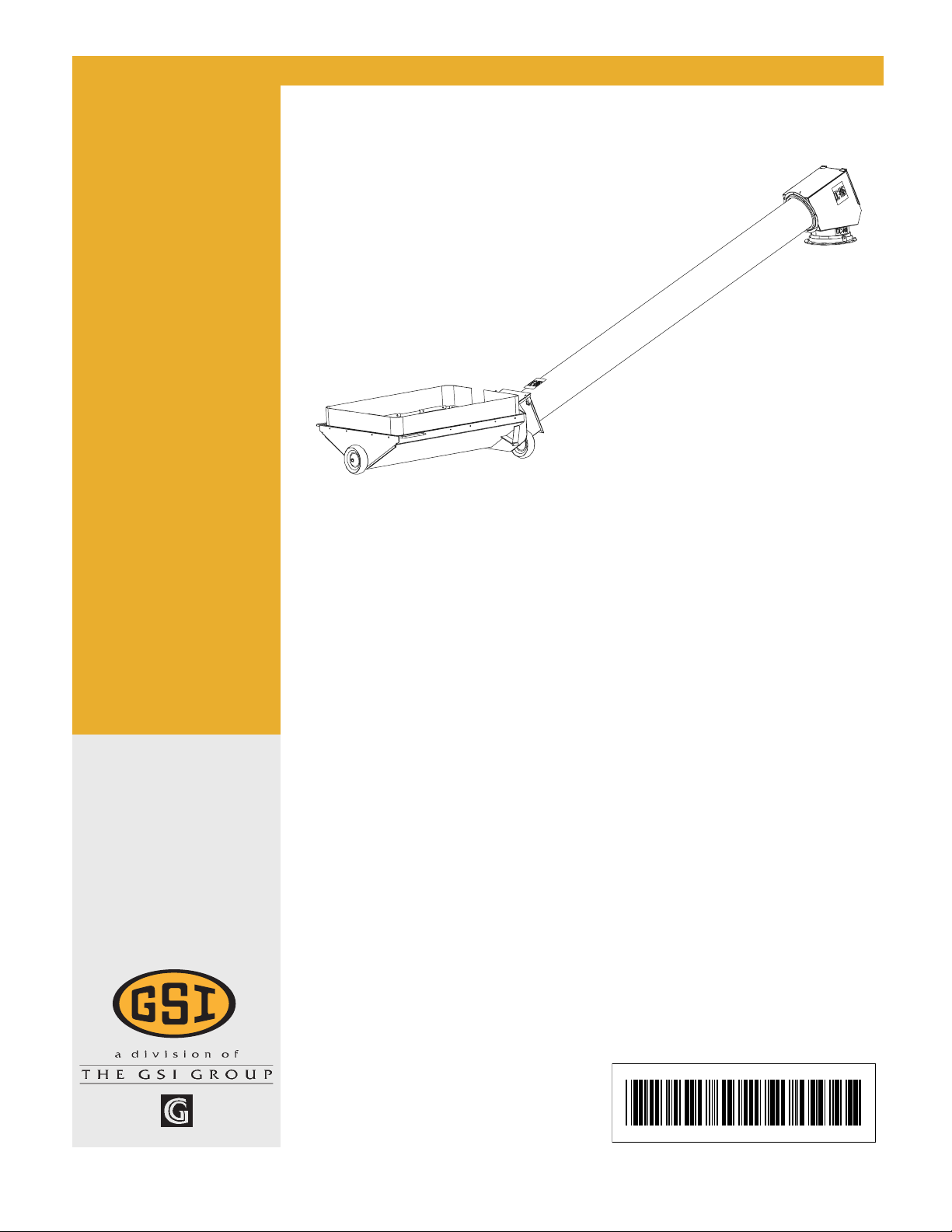
8", 10", & 12" BE-SAW
Unload Auger
Assembly & Operation Manual
PNEG-1391
Date: 5-5-06
PNEG-1391
Page 2
Model Number of My BE-SAW:
Date Delivered:
Date Installed:
The manufacturer reserves the right to improve its product whenever possible
and practical to do so. We reserve the right to change, improve and modify
products at any time without obligation to make changes, improvements and
modifications on equipment sold previously.
Page 3

TABLE OF CONTENTS
Introduction.............................................................................. 4
BE-SAW Numbering System................................................... 5
Safety ..................................................................................... 6
Decals .................................................................................... 12
Assembly ................................................................................ 14
Assemble Hopper to Incline (8" &10") ............................... 14
Assemble Hopper to Incline (12") ...................................... 16
Assemble Rubber Belting (8", 10", & 12") ......................... 19
Table of Content
Optional Low Profile Hopper (10" & 12") ........................... 20
Incline Tube to Bucket Elevator Boot ................................... 22
BE-SAW Transition ............................................................ 23
Start-Up .................................................................................. 24
Operation ................................................................................ 25
Shutdown ................................................................................ 26
Maintenance ........................................................................... 27
Troubleshooting....................................................................... 29
Parts ....................................................................................... 30
Hardware Location Charts ...................................................... 50
3PNEG-1391 8",10", & 12" BE-SAW Augers
Page 4
Introduction
INTRODUCTION
GENERAL OVERVIEW
The Bucket Elevator Swing Away Auger (BE-SAW) is
pimarily used for unloading grain trucks/wagons. The
BE-SAW hopper is placed under the unload chute
and augers the grain to a new location.
The manufacturer reserves the right to improve its
product whenever possible and practical to do so.
We reserve the right to change, improve and modify
products at any time without obligation to make
changes, improvements and modifications on equipment sold previously.
The BE-SAW Augers have been designed and
manufactured to give years of dependable service.
The care and maintenance of this equipment will
effect the satisfaction and service obtained. By
observing the instructions and suggestions we have
recommended, the owner should receive competent
service for many years. If additional information or
assistance should be required, please contact your
dealer or the manufacturer.
CAPACITY
A. The capacities of augers or screw
conveyers varies greatly under varying
conditions. The following factors play a role in
the performance of the auger:
• Speed
• Angle of operation
• Moisture content
• Amounts of foreign matter
• Methods of feeding
• Different materials
B. An auger operating at a 25° incline might
experience 20% less capacity than an auger
operating horizontally. Twenty-five percent
(25%) moisture could cut capacity by as much
as 40% under some conditions.
GENERAL INFORMATION
READ THIS MANUAL carefully to learn how to properly
use and install equipment. Failure to do so could result
in personal injury or equipment damage.
INSPECT the shipment immediately upon arrival. The
Customer is responsible for ensuring that all quantities
are correct. Report any damage or shortages by
recording a detailed description on the Bill of Lading to
justify the Customer’s claim from the Transport Firm.
THIS MANUAL SHOULD BE CONSIDERED a
permanent part of your equipment and should be easily
accessible when needed.
WARRANTY is provided as part of the company’s
support program for customers who use and maintain
their equipment as described in the manual. The
warranty is explained on the warranty page located on
inside back cover.
This warranty provides you the assurance that the
company will back its products where defects appear
within the warranty period. Should the equipment be
abused, or modified to change its performance beyond
the factory specifications, the warranty will become void
and field improvements may be denied.
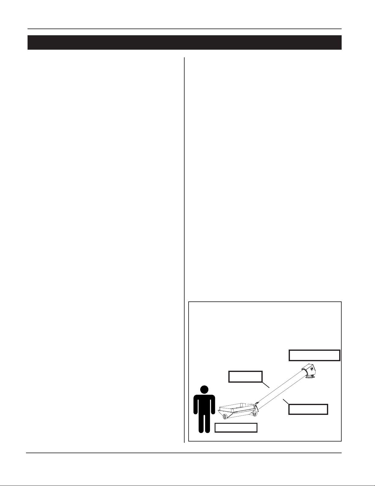
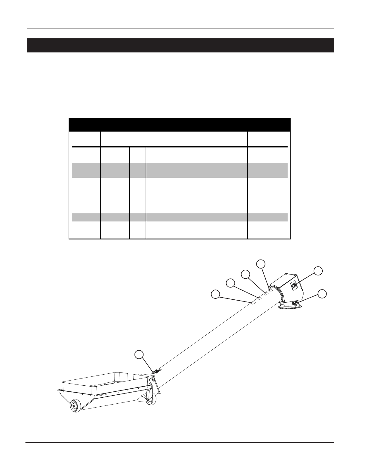
For the purpose of this manual, if you stand at
the intake end of the auger looking towards
the discharge end, your left is the left side of
the auger; your right is the right side of the
auger.
Discharge End
Left Side
Right Side
Intake End
4
PNEG-1391 8",10", & 12" BE-SAW Augers
Page 5
Introduction
w
w
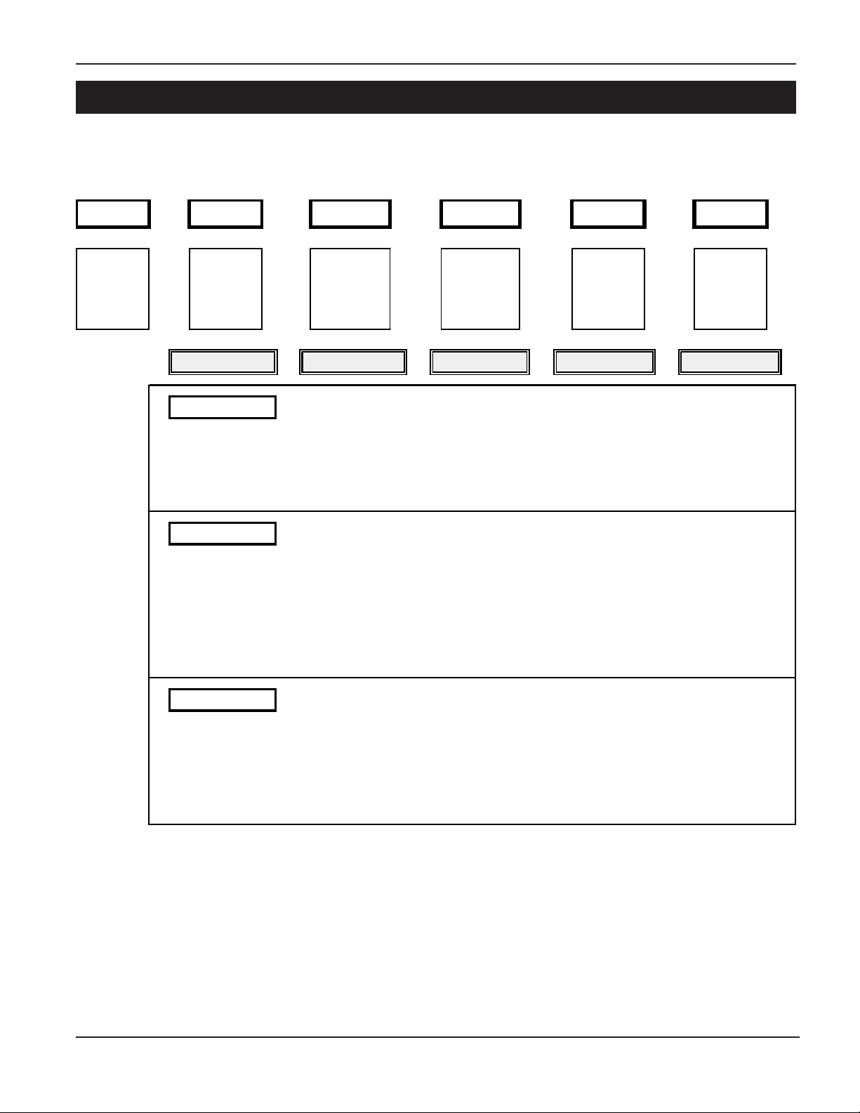
BE-SAW Numbering System
SA XX X XX XX X
Product Diameter Hopper Nominal Capacity Hopper
Line of Profile Length of Flight
Screw of BESAW Thickness
Tube
ChoiceChoi ce Choi ce Choice Choice
08 = 8" Screw
S = Std Profile 10 = 115.875" 15 = 1500 BPH
12 = 144" lg 20 = 2000 BPH
25 = 2500 BPH
30 = 3000 BPH
A = Standa r d
B = 1/4" Thick
10 = 10" Scre
12 = 12" Scre
S = Std Profile 10 = 120" lg 40 = 4000 BPH
13 = 153" lg 50 = 5000 BPH
L = Low-Profile 10 = 115.125"
13 = 148.125"
S = Std Profile 13 = 13' 3" 70 = 7000 BPH A = Standard
15 = 15' 3"
L = Low-Profile 70 = 7000 BPH
12 = 12' 8"
80 = 8000 BPH
A = Standa r d
B = 1/4" Thick14 = 160" lg 56 = 5600 BPH
B = 1/4" Thick
A = Standa r d
B = 1/4" Thick14 = 14' 8" 80 = 8000 BPH
PNEG-1391 8",10", & 12" BE-SAW Augers
5
Page 6
Safety
SAFETY GUIDELINES
This manual contains information that is important for you, the owner/operator, to know and
understand. This information relates to protecting personal safety and preventing
equipment problems. It is the responsibility of the owner/operator to inform anyone
operating or working in the area of this equipment of these safety guidelines. To help you
recognize this information, we use the symbols that are defined below.
Please read the manual and pay attention to these sections. Failure to read this manual
and it’s safety instructions is a misuse of the equipment and may lead to serious injury or death.
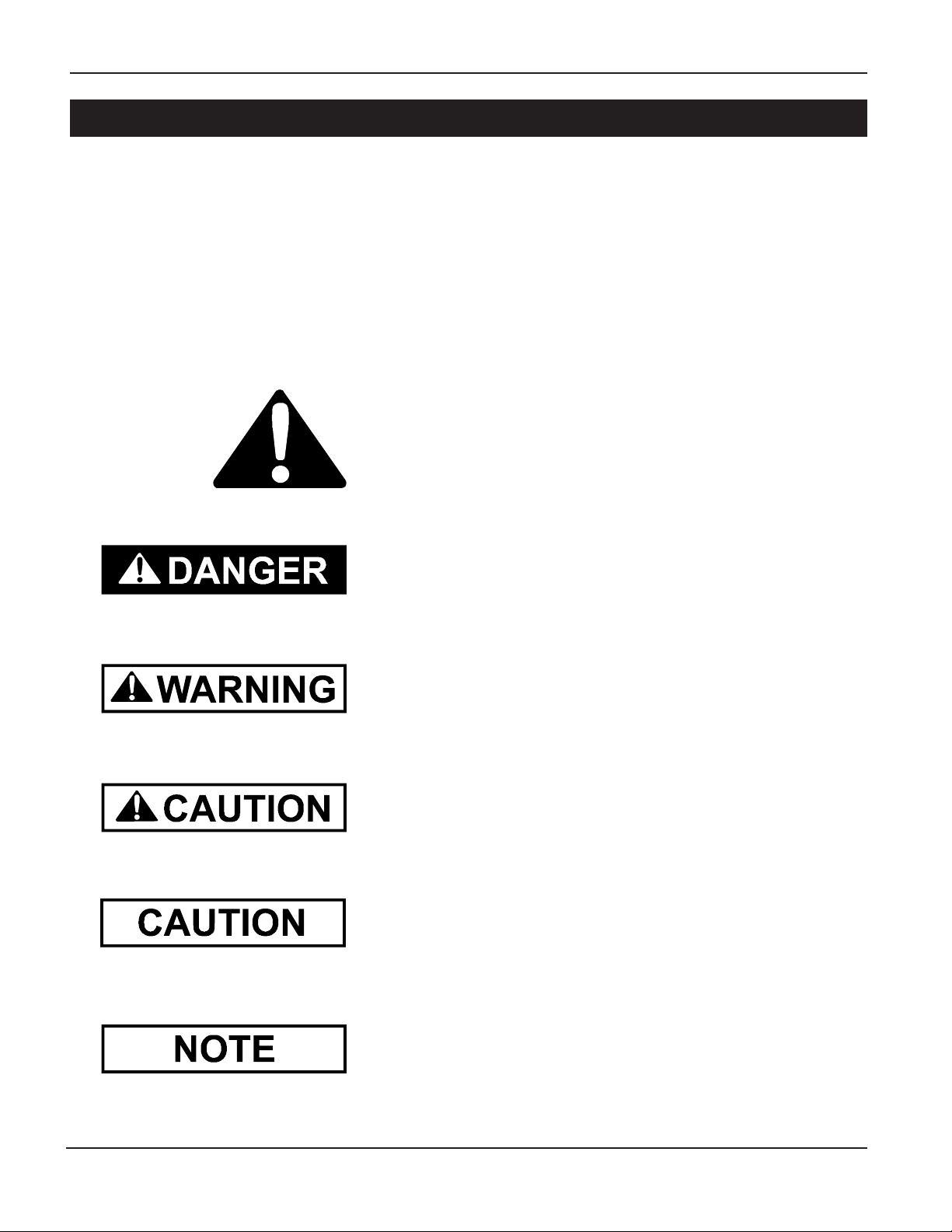
This is the safety alert symbol. It is used to alert you to
potential personal injury hazards. Obey all safety
messages that follow this symbol to avoid possible
injury or death.
DANGER indicates an imminently hazardous situation which, if
not avoided, will result in death or serious injury.
WARNING indicates a potentially hazardous situation which, if not
avoided, could result in death or serious injury.
CAUTION indicates a potentially hazardous situation which, if not
avoided, may result in minor or moderate injury.
CAUTION used without the safety alert symbol indicates a potentially
hazardous situation which, if not avoided, may result in property
damage.
NOTE indicates information about the equipment that you
should pay special attention to.
6
PNEG-1391 8",10", & 12" BE-SAW Augers
Page 7
Safety
SAFETY INSTRUCTIONS
GSI’s principle concern is your safety and the safety of others associated with grain handling equipment.
We want to keep you as a customer. This manual is to help you understand safe operating procedures and
some problems which may be encountered by the operator and other personnel.
As owner and/or operator, it is your responsibility to know what requirements, hazards and precautions exist,
and to inform all personnel associated with the equipment. Avoid any alterations to the equipment. Such
alterations may produce a very dangerous situation, where SERIOUS INJURY or DEATH may occur.
This equipment shall be installed in accordance with the current installation codes and applicable regulations which should be carefully followed in all cases. Authorities having jurisdiction should be consulted
before installations are made.
OPERATE UNLOAD EQUIPMENT PROPERLY
Make sure ALL equipment is locked in position before operating.
NEVER start equipment until ALL persons are clear of the work area.
Be sure all operators are adequately rested and prepared to
perform all functions of operating this equipment.
NEVER allow any person intoxicated or under the influence of alcohol or drugs
to operate the equipment.
NEVER work alone.
Make sure someone is nearby who is aware of the proper shutdown sequence in the event of an accident or emergency.
ALWAYS think before acting. NEVER act impulsively around the equipment.
NEVER allow anyone inside a bin, truck or wagon which is being unloaded by
an auger or conveyor. Flowing grain can trap and suffocate in seconds.
Use ample overhead lighting after sunset to light the work area.
Keep area around intake free of obstacles such as electrical cords, blocks,
etc. that might trip workers.
Operate
Unload
Equipment
Safely
NEVER drive, stand or walk under the equipment.
Use caution not to hit the auger when positioning the load.
ALWAYS lockout ALL power to the equipment when finished
unloading a bin.
PNEG-1391 8",10", & 12" BE-SAW Augers
7
Page 8
Safety
FOLLOW SAFETY INSTRUCTIONS
Carefully read all safety messages in this manual
and on your machine safety signs. Keep signs in
good condition. Replace missing or damaged
safety signs. Be sure new equipment components
and repair parts include the current safety signs.
Replacement safety signs are available from the
manufacturer.
Learn how to operate the machine and how to use
controls properly. Do not let anyone operate without
instruction.
Keep your machinery in proper working condition.
Unauthorized modifications to the machine may
impair the function and/or safety and affect machine
life.
If you do not understand any part of this manual
and need assistance, contact your dealer.
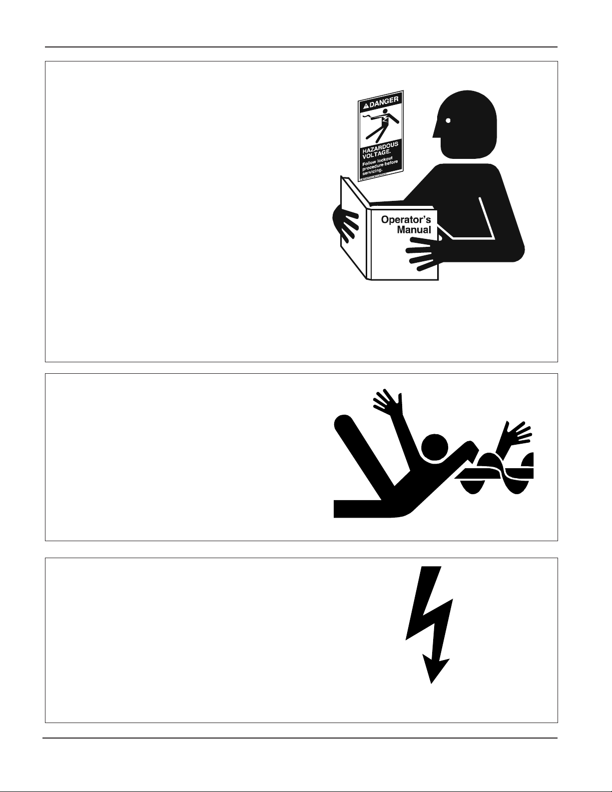
STAY CLEAR OF ROTATING PARTS
Entanglement in rotating augers will cause serious
injury or death.
Keep all shields and covers in place at all times.
Wear close fitting clothing. Stop and lock out power
source before making adjustments, cleaning, or
maintaining equipment.
OPERATE MOTOR PROPERLY
Do not operate electric motor equipped units until
motors are properly grounded.
Disconnect power on electrical driven units before
resetting motor overloads.
Do not repetitively stop and start the drive in order
to free a plugged condition. Jogging the drive in
this type of condition can damage the equipment
and/or motor components.
8
Electric Shock Hazard.
PNEG-1391 8",10", & 12" BE-SAW Augers
Page 9
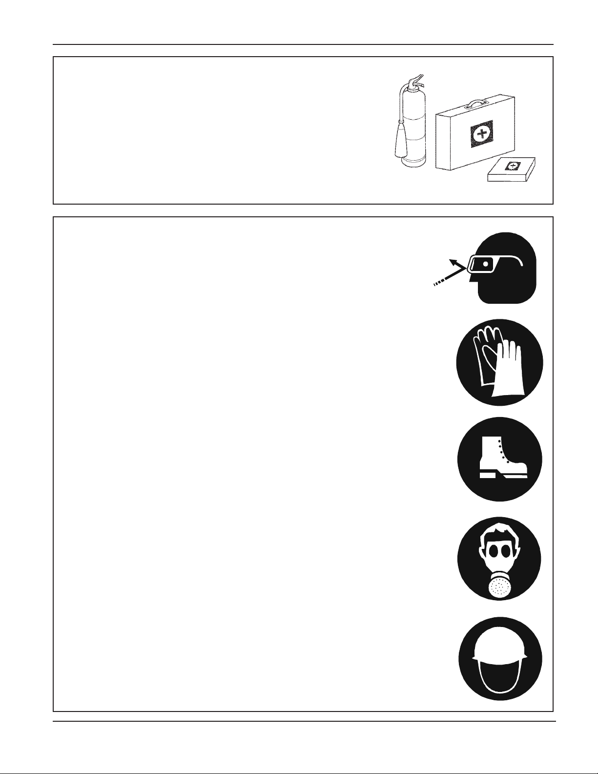
PREPARE FOR EMERGENCIES
Be prepared if fire starts.
Keep a first aid kit and fire extinguisher handy.
Keep emergency numbers for doctors, ambulance
service, hospital, and fire department near your
telephone.
WEAR PROTECTIVE CLOTHING
Safety
Wear close fitting clothing and safety equipment
appropriate to the job.
Safety glasses should be worn at all times to
protect eyes from debris.
Wear gloves to protect your hands from sharp
edges on plastic or steel parts.
A respirator may be needed to help prevent
breathing potentially toxic fumes and dust.
Wear hard hat and steel toe boots to help protect
your head and toes from falling debris.
Eye Protection
Gloves
Steel Toe
Boots
PNEG-1391 8",10", & 12" BE-SAW Augers
Respirator
Hard Hat
9
Page 10

Safety
OPERATOR QUALIFICATIONS
A. The User/Operator must be competent and experienced to operate auger equipment. Anyone who
works with or around augers must have good common sense in order to be qualified. These persons
must also know and meet all other qualifications, such as:
1. Any person who has not read and/or does not understand all operation and safety
procedures is not qualified to operate any auger systems.
2. Certain regulations apply to personnel operating power machinery. Personnel under
the age of 18 years may not operate power machinery, including augers. It is your
responsibility, as owner and/or supervisor, to know what these regulations are in your
area or situation.
3. Unqualified or incompetent persons are to remain out of the work area.
4. O.S.H.A. (Occupational Safety & Health Administration) regulations state:
"At the time of initial assignment and at least annually thereafter, the employer shall
instruct every employee in the safe operation and servicing of all equipment with
which the employee is, or will be involved." (Federal Occupational Safety & Health
Standards for Agriculture. Subpart D, Section 19287.57 (a) (6).
B. As a requirement of OSHA, it is necessary for the employer to train the employee in the safe operating
and safety procedures for this auger. We included this sign-off sheet for your convenience and
personal record keeping. All unqualified persons are to stay out of the work area at all times. It is
strongly recommended that another qualified person who knows the shutdown procedure is in the
area in the event of an emergency. A person who has not read this manual and understands all
operating and safety instructions is not qualified to operate the machine.
Date Employer's Signature Employee 's Signature
10
PNEG-1391 8",10", & 12" BE-SAW Augers
Page 11
Y
st
Safety
SAFET
Replace missing guards and shields
FREE OF CHARGE!
Our equipment is built to provide many years of dependable service to our customers
through durable craftsmanship.
One of the most important aspects of our engineering is SAFETY 1
throughout all product lines. Safety is NO ACCIDENT!
That is why we are implementing its SAFETY 1st program. Should you ever need
guards, shields, safety decals, or owner/operator manuals, simply contact us, and
we will supply you with them FREE OF CHARGE!
1
st
design
While it is our main goal to be the world leader in auger manufacturing, it is always
our first priority to keep our customers safe.
If you need any of the above listed safety items or have safety questions, please
contact us:
The GSI Group
PO Box 20
1004 E. Illinois Street
Assumption, IL 62510
Ph: 217-226-4421
PNEG-1391 8",10", & 12" BE-SAW Augers
11
Page 12
Decals
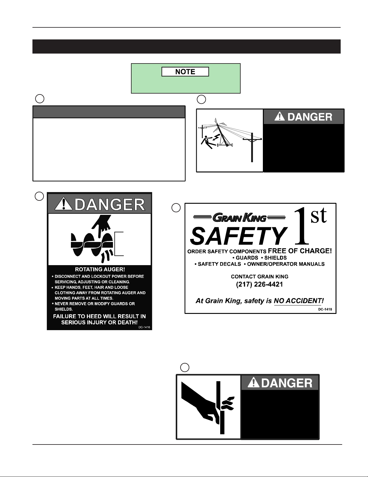
Safety Decals
The Safety Decals listed below are included with the auger. The following page shows the
locations of the decals on the auger. The following pages show a sample of each decal.
Inspect all decals and replace any that are illegible, worn, or missing. Contact your dealer or
the factory to order replacement decals.
Safety Decals
Ref. # Part # Qty. Description Size
1 DC-1446 1
2 DC-1412 1
3 DC-1416 1
4 DC-1418 1
5 DC-1411 1
Caution—General Statements 1-12
Main Auger Housing)
Danger—Electrocution
Hous ing)
Danger—Rotating Auger
of Tube Near Hopper, On Side of Spout
Head, On Underside of Inlet Hopper, On
Side of Inlet Hopper, On Inlet Hopper
Clean-Out Door)
Safety First
Danger—Shear Point
Hopper)
—(On Main Auger Housing) 4-7/8" x 3-1/2"
(On Main Auger
(On Intake End
(On Front of Inlet
(On
8-1/4" x 4-1/8"
4-1/2" x 5-1/2"
4-1/2" x 2-1/16"
8" x 3-3/8"
3
1
3
2
4
5
3
12
PNEG-1391 8",10", & 12" BE-SAW Augers
Page 13
Safety Decals
Decals are not shown actual size.
Decals
1
NOTICE
1. READ AND UNDERSTAND THE INSTALLATION & OPERATION MANUAL AND ALL SAFETY
INSTRUCTIONS BEFORE OPERATING EQUIPMENT.
2. DO NOT OPERATE WHILE UNDER THE INFLUENCE OF DRUGS OR ALCOHOL.
3. DO NOT OPERATE UN LESS ALL SAFET Y EQUIPMENT, SWITCHES, GUARDS AND SHIELDS
ARE SECURELY IN PLACE AND OPERATIONAL.
4. BE SURE EVERYONE IS CLEAR OF THE EQUIPMENT BEFORE ATTEMPTING TO OPERATE
OR MOVING THE MACHINE.
5. ALLOW ONLY TRAINED PERSONNEL IN the OPERATING AREA.
6. KEEP HANDS, FEET, HAIR AND CLOTHING AWAY FROM MOVING PARTS.
7. DI SCONNE CT AND LOCKOU T POWER BEFO RE ADJUSTING OR SERVICIN G.
8. ELECTRICAL WIRING OR SERVICE WORK MUST BE PERFORMED BY A QUALIFIED
ELECTRICIAN. IT MUST MEET ALL STATE AND LOCAL ELECTRICAL CODES.
9. EMPTY AUGER AND LOWER TO TR ANSPORT POSITION BEFORE TRANSPORTIN G.
10. MAKE CERTAIN ALL ELECTRIC MOTORS ARE GROUNDED.
11. NEVER MOVE MACHINE MANUALLY. ALWAYS USE A TOWING VEHICLE.
12. KEEP CHILDREN AWAY FROM WORK AREA AT ALL TIMES.
3
DC-1446
2
ELECTROCUTION!!
STAY CLEAR OF POWER LINES!
• THIS EQUIPMENT IS NOT INSULATED FROM ELECTRIC SHOCK.
• KEEP EQUIPMENT AWAY FROM POWER LINES.
• ELECTROCUTION CAN OCCUR WITH OR WITHOUT DIRECT
CONTACT.
FAILURE TO HEED WILL RESULT
IN SERIOUS INJURY OR DEATH!
DC-1412
4
PNEG-1391 8",10", & 12" BE-SAW Augers
5
SHEAR POINT
KEEP FINGERS, HANDS, HAIR AND
LOOSE CLOTHING AWAY FROM
MOVING PARTS.
FAILURE TO HEED
WILL RESULT IN
SERIOUS INJURY OR DEATH!
DC-1411
13
Page 14
Assembly
8" & 10" Standard Profile Hopper Assembly
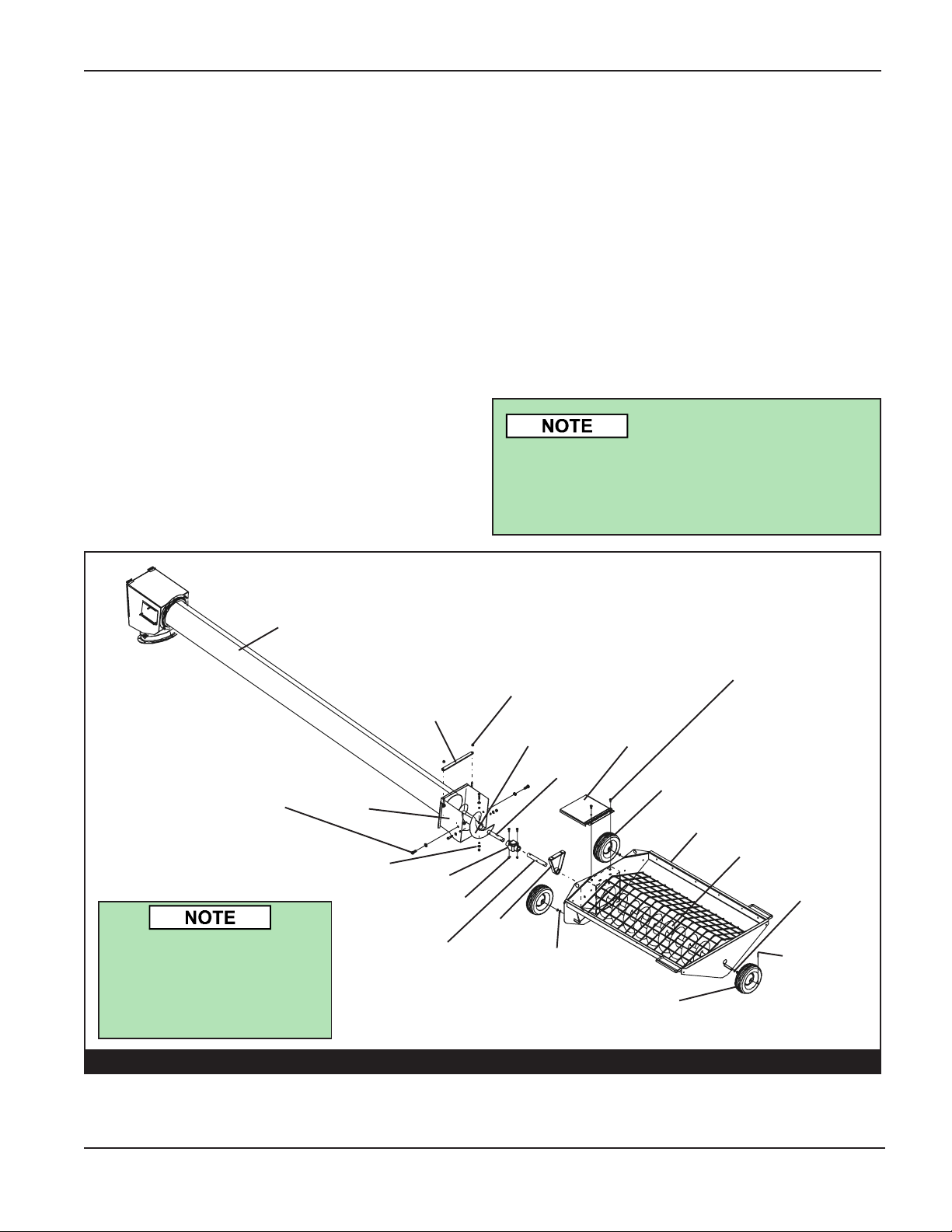
1. ASSEMBLE HOPPER 8" & 10" AND INCLINE TUBE (See Figure 1-B)
A. Apply grease to the wheel shafts of the
hopper.
B. Attach the hopper wheels to the wheel shafts
using three (3) 5/8" flat washers and one (1)
3/16" x 1-1/2" cotter pin for each wheel. Note:
One (1) to two (2) washers should be used
as spacers between the hopper and the
wheel. Use one (1) washer between the wheel
and the cotter pin.
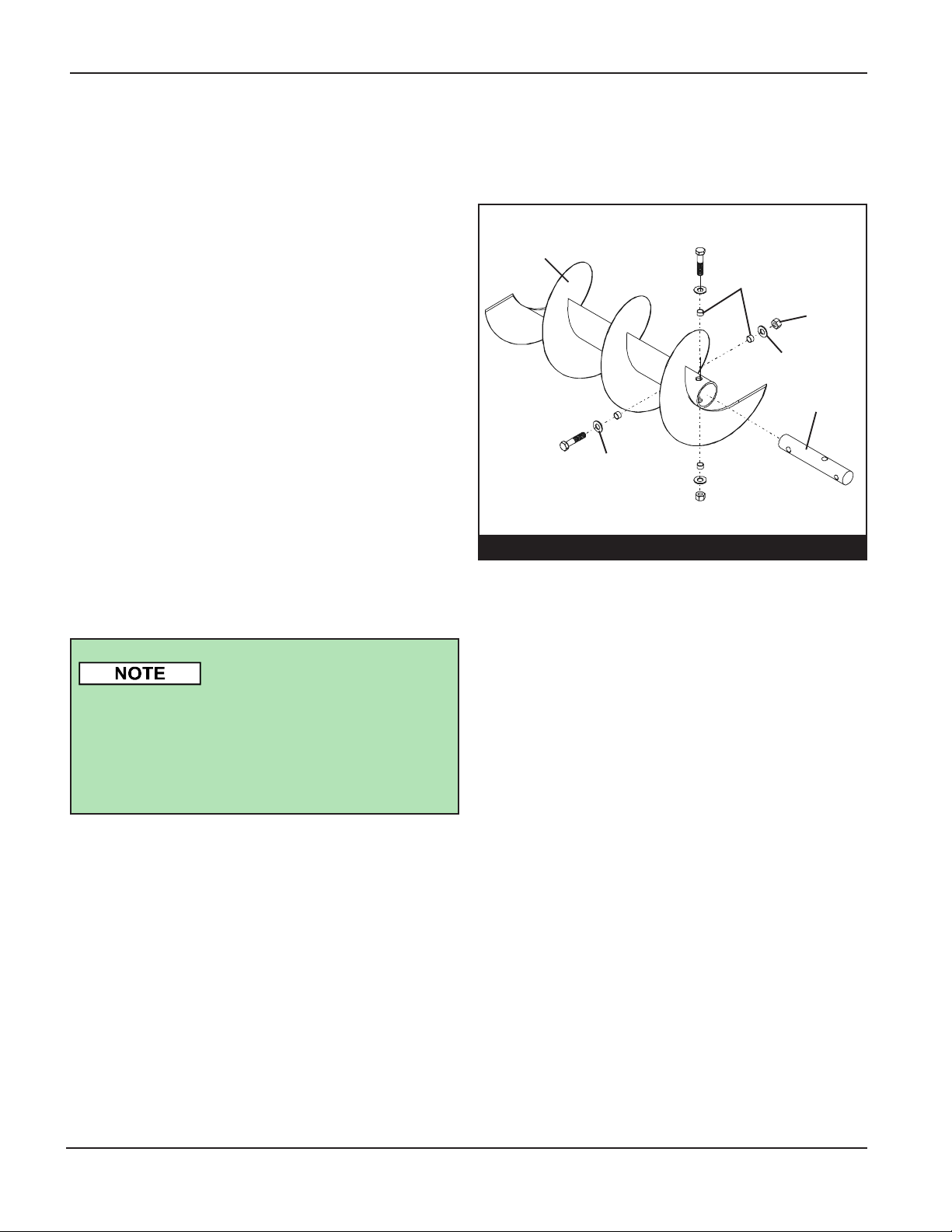
C. Use the following hardware to bolt the
incline tail stub into the incline flight: (See
Figure 1-A)
• Four (4) rubber sleeves
• Two (2) hex head (Grade 5) cap screws:
For 8" models, use 3/8" x 3" long cap
screws. For 10" models, use 7/16" x
3-1/2" long cap screws.
• Four (4) flat washers
IMPORTANT: When tightening nylon locknuts, make
sure they are firmly secured
against the rubber sleeves,
but not so tight that they lay
against the flight tube.
Leave a gap of approximately 1/16".
Flight Connections
Incline
Flight
Flat
Washer
FIGURE 1-A
Rubber Sleeve
Nylon
Locknut
Flat
Washer
Tail Stub
E. Attach the u-joint to the bearing stub in the
hopper using one (1) hex head cap screw and
nylon locknut. For 8" models, use a
5/16" x 2-1/2" long (Grade 5) hex head cap
screw. For 10" models, use a 3/8" x 3" long
(Grade 5) hex head cap screw.
Note: Loosen the hanger bearing hardware
for later adjustment.
D. Attach the u-joint to the incline tail stub using
one (1) hex head cap screw and nylon locknut.
For 8" models, use a 5/16" x 2-1/2" long
(Grade 5) hex head cap screw. For 10"
models, use a 3/8" x 3" long (Grade 5) hex
head cap screw.
14
PNEG-1391 8",10", & 12" BE-SAW Augers
Page 15
8" & 10" Standard Profile Hopper Assembly
1. ASSEMBLE 8" & 10" HOPPER AND INCLINE TUBE (CONT.)
Assembly
F. Attach the lower end of the incline tube to the
front of the flexible swing-out hopper using the
following hardware:
• Two (2) 1/2" x 1-1/4" long (Grade 5) hex
head cap screws
• Four (4) Flat washers
• Nylon locknuts
G. Install the bolt heads onto the inside but DO
NOT tighten completely because the coupler
box must be allowed to pivot.
H. Center hanger bearing on bearing shaft
between hopper flight and u-joint, then tighten.
Swing Out Hopper
Incline Tube
Cover Strap
I. Fasten the hinged cover to the front of the
flexible swing-out hopper using two (2) 5/16"
x 3/4" long (Grade 5) hex head cap screws,
flat washers, and nylon locknuts.
J. Install the cover strap over the lid onto the
3/8" stub, which is welded to the box on the
lower end of the incline tube. Use 3/8" nylon
locknuts to hold the straps on the stud.
IMPORTANT: DO NOT
tighten the locknuts down.
The hinged cover must be
able to slide under the
strap when the incline tube
is tilted at different angles.
5/16" x 3/4" Long (Grade 5) Hex
Head Cap screws, Flatwashers,
and Nylon Locknuts
3/8" Locknuts
Incline
Flight
Hinged
Cover
1/2" x 1-1/4" Long (Grade 5)
Hex Head Cap screw with Flat
Washers and Nylon Locknuts
Note: Install so bolt heads are
on the inside.
The hopper hanger bearing and
bearing stub are preassembled to the
flexible swing-out hopper. In this
assembly drawing, those parts were
exploded away from the hopper to
better show the proper assembly of
the other parts.
Coupler
Box
Rubber Sleeve
U-Joint
8" - 5/16"x 2-1/2"
10" - 3/8" x 3"
PNEG-1391 8",10", & 12" BE-SAW Augers
Hanger
Bearing
Stub
Bearing
FIGURE 1-B
Tail Stub
2 Flat
Washers
Hopper Wheel
Hopper
Hopper Flight
2 Flat
Washers
3/16" x 1-1/2"
Long Cotter Pin
Hopper Wheel
15
Page 16
Assembly
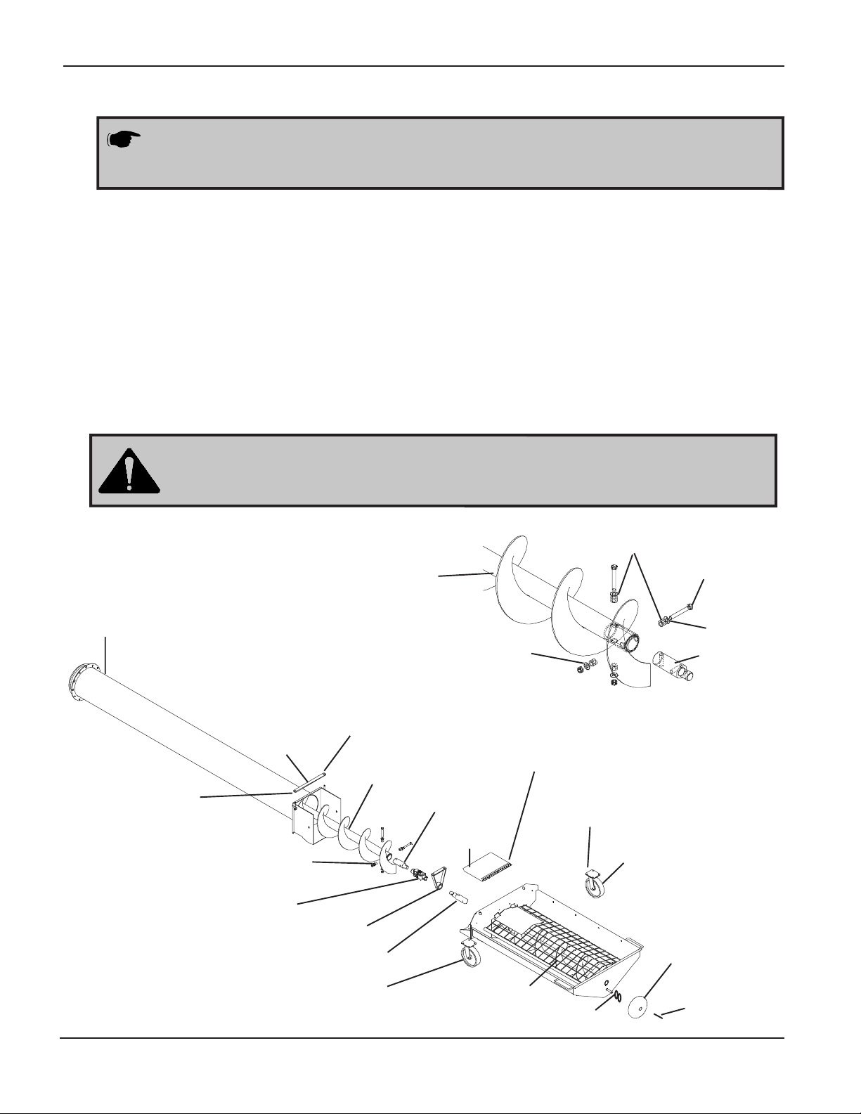
12" Standard Profile Hopper Assembly
The hopper hanger bearing and bearing stub are pre-assembled on the swingaway hopper. Therefore, in the drawings, those parts were exploded away from
the hopper to better show the proper assembly of the other components.
2. ASSEMBLE 12” HOPPER AND INCLINE
TUBE ASSEMBLY
A. Attach the rubber hopper wheel to the back of
the swing-away hopper using two (2) 5/8" flat
washers and 3/16" x 2" cotter pins. (See Fig.
2-B)
B. Fasten two (2) hopper caster wheels to front of
hopper using (4) 3/8" x 1-1/4" long (grade 5) hex
head capscrews and nylon locknuts for each
wheel.
Tighten locknuts so the flat washers are firmly against the rubber sleeves.
DO NOT tighten so tight that the flat washers are against the flight tube.
Leave about 1/16" gap.
INCLINE TUBE
INCLINE
FLIGHT
C. Remove the incline flight from the incline tube.
D. Attach lower end of the incline tube to the front of
the swing-away hopper. Use two (2) 5/8" x
1-1/4" long (grade 5) hex head capscrews, flat
washers, and locknuts.
E. Connect incline tail stub into the incline flight using
four (4) rubber sleeves, two (2) 1/2" x
3-3/4" long (grade 5) hex head capscrews, flat
washers, and nylon locknuts. (See Fig. 2-A)
RUBBER
SLEEVE
LOCKNUT
FLAT
WASHER
FLAT WASHER
TAIL STUB
5/8" X 1 1/4" LONG
(GRADE 5) HEX HEAD
CAPSCREW WITH
FLATWASHWER AND
NYLON LOCKNUTS
NOTE: INSTALL SO
BOLT HEADS ARE ON
THE INSIDE
FIG. 2-B
16
COVER
STRAP
RUBBER SLEEVE
U-JOINT
BEARING HANGER
BEARING STUB
CASTER WHEEL
3/8" LOCKNUT
INCLINE
FLIGHT
TAIL STUB
HOPPER FLIGHT
FIG. 2-A
5/16" X 3/4" LONG (GRADE 5)
HEX HEAD CAPSCREWS,
FLATWASHERS AND NYLON
LOCKNUTS
3/8" X 1 1/4" LONG (GRADE 5)
HEX HEAD CAPSCREW AND
HINGED
COVER
(2) FLAT
WASHERS
NYLON LOCKNUTS
CASTER
WHEEL
HOPPER
WHEEL
3/16" X 2"
LONG
COTTER
PIN
PNEG-1391 8",10", & 12" BE-SAW Augers
Page 17
Assembly
12" Standard Profile Hopper Assembly
2. ASSEMBLE 12” HOPPER AND IN- LINE TUEBE ASSEMBLY (CONT.)
F. Using a 3/8" x 3" long (grade 5) hex head capscrew and nylon locknut, attach the u-joint to the incline
tail stub.
G. Slide the lower end of the inclined flighting (the end with the u-joint fastened) down into the upper end of
the incline tubing. Slide the flighting down until the u-joint is near the swing-away hopper bearing stub.
H. Connect the u-joint on the flighting to the bearing stub in the swing-away hopper using a 3/8" x 3" long
(grade 5) hex head capscrew and nylon locknut.
I. Bolt hinged cover to the front of the swing-away hopper using two (2) 5/16" x 3/4" long (grade 5) hex
head capscrews, flat washers, and nylon locknuts.
DO NOT tighten the nuts down. The hinged cover
MUST be able to slide un-
der the strap when the incline tube is tilted at different angles.
J. Install cover strap over lid onto the 3/8" stub that is welded to the box on the lower end of the incline
tube. Use the 3/8" nylon locknuts to hold the straps onto the stub.
5/8" X 3-1/2" (GRADE 5)
HEX HEAD CAPSCREW
INCLINE FLIGHT
STOP RING
RING
INCLINE TUBE
5/8" LOCKNUT
FIG. 2-C
PNEG-1391 8",10", & 12" BE-SAW Augers
19/32" LONG
SPACER
BUSHING
FLAT WASHER
3/8" X 1 3/4" LONG
(GRADE 5) HEX
HEAD CAPSCREW,
FLAT WASHER AND
LOCKWASHER
17
Page 18

Assembly
12" Standard Profile Hopper Assembly
2. ASSEMBLE 12" HOPPER AND IN-LINE TUBE ASSEMBLY (CONT.)
L. Slide head end of the incline flight onto the spout studs. Secure the incline flight in place by using a
5/8" x 3-1/2" long (grade 5) hex head capscrew with a locknut. (See Fig. 2-C on page 17.)
3/8" X 1 3/4"
LONG HEX
HEAD
CAPSCREW
WELDED TO
SPOUT
STOP RING
WELDED TO
FIG. 2-D
INCLINE
TUBE
M. Slide incline tube onto the back of the downspout, lining up the holes on the incline ring with the bolts
welded onto the down spout. Fasten using eight (8) 19/32" long spacer bushings, eight (8)
3/8" x 1-3/4" long hexhead capscrews, eight (8) flat washers, and eight (8) 3/8" nylon locknuts.
Be sure to install the spacer bushings between the back of the spout and
the ring. After the 3/8" nylon locknuts are tightened, the spout
MUST BE
ABLE TO SWIVEL on the incline tube.
18
PNEG-1391 8",10", & 12" BE-SAW Augers
Page 19

Assembly
3. ASSEMBLE 8", 10", & 12" HOPPER RUBBER BELTING ASSEMBLY
A. Place the rubber belting into the inside of the swing-away hopper.
B. Loosely attach the rubber belting using ten (10) attachment clips and two (2) 1/4” x 1” long hex head
cap screws and nylon locknuts for each clip. The points of the clips should point up and the bolt
heads should be inside the hopper. Use the bolt holes positioned around the upper edge of the
hopper as a guide.
C. Position the belting inside the clips with the belting edge resting on the bolts. As shown on the diagram
on the previous page, the belting should not cover the output end of the hopper. Keep the belting end
within one (1) inch of the clip end.
D. Position the belting evenly around the hopper and through the corners.
E. Tighten the bolts and nuts so that the clip points draw into the belting and the smooth edge of the clips
is in contact with the belting.
Belt Hopper Detail
Attachment
Clips
Rubber
Hopper
Belting
1/4" x 1" Hex Head
Capscrew and Nylon
Locknut
Attachment Clip
1/4" x 1"
Hex Head
Cap
FIGURE 3-B
Rubber
Belting
1/4"
Nut
Hopper
FIG. 3-A
PNEG-1391 8",10", & 12" BE-SAW Augers
Swing-Out
Hopper
19
Page 20

Assembly
4. OPTIONAL 10" & 12" LOW PROFILE HOPPER ASSEMBLY INSTRUCTIONS (See Figure 4-A)
A. Install the hopper wheels to the hopper using
four (4) 5/8" x 9-3/4" long clevis pins, four (4)
wheel spacer bushings and four (4) 1-1/4"
cotter pins. Install the hopper wheels so the
front wheels are tilted in towards the incline
tube and the rear wheels are tilted away from
the hopper chain guard. Basically, you want
to tilt your wheels so they follow the arc made
when you move the hopper. (See detail 4-B)
There are two installation
heights for the hopper wheels.
For the shortest hopper
profile, use the upper set of
holes. Also use the holes to
angel the wheels by using
opposite holes.
B. Fasten the U- Joint to the incline tail stub us-
ing one 3/8" x 3" long (grade 5) HHCS and
stover nut.
C. Connect the U-Joint to the power shaft in the
swing-out hopper using one (1) 3/8" x 3" long
(grade 5) HHCS and stover nut.
G. Low Profile Swing-Out Hopper Rubber
Belting Assembly (See Figure 4-A)
1. Install the rubber belting into the inside of
the swing out hopper. Use ten (10) long
and four (4) short attachment clips to install
the belting. Two (2) 1/4" x 1" long hex head
capscrews and nylon locknuts are used
for each clip. Loosely attach each clip with
grip teeth of clips up and with bolt heads
inside the hopper. Use bolt holes
positioned around upper edge of hopper.
2. Set the belting inside the clips with the
belting edge resting on the bolts. (See
Figure 4-C) The belting does not go
completely across the output end of the
hopper. The belting is notched to
accommodate the center guard support
at the rear of the hopper. Begin installing
the belting at this point and work each way
toward the hopper discharge. Keep the
belting end within one inch of the clip end.
Position the belting evenly around the
hopper and through the corners.
D. Fasten the lower end of the incline tube to the
front of the swing away hopper. Use two 1/2"
x 1-1/2" long (grade 5) HHCS, flat washers,
and nylon locknuts.
Install bolt heads to the
inside and DO NOT tighten
completely. The coupler
box must be able to pivot.
E. Bolt hopper lid to the front of the swing out
hopper using three (3) 5/16" x 3/4" long (grade
5) HHCS flat washers, and nylon locknuts.
F. Install lid strap onto 3/8" stubs welded onto
lower end of incline tube. Hold the straps on
the stud with 3/8" nylon locknuts.
Do NOT tighten the nuts
down. The lid straps must
be allowed to slide when
the incline tube is tilted at
different angles.
3. Tighten the bolts and nuts to where the
clip points draw into the belting and the
smooth edge of the clips is in contact with
the belting.
Belt Hopper Detail
Hopper
Attachment Clip
1/4" Nylon
Locknut
1/4" x 1"
Hex Head Cap
Hopper
FIGURE 4-C
20
PNEG-1391 8",10", & 12" BE-SAW Augers
Page 21

Low Profile Hopper - 10" & 12" Only
Assembly
1/4" X 1" LONG HHCS
AND LOCKNUT
COTTER PIN
LONG
CLIP
5/8" X 9-3/4"
CLEVIS PIN
SHORT
CLIP
SPACER BUSHING
WHEELS
5/16" X 3/4" LONG HHCS,
FLAT WASHERS, AND
NYLON LOCKNUTS
HOPPER LID
U-JOINT
RUBBER
BELT
3/8" LOCKNUT
LID STRAP
3/8" X 3" LONG
(GRADE 5) BOLT
& STOVER NUT
INCLINE
TUBE
1/2" X 1-1/2"
LONG (GRADE 5)
HHCS AND
NYLON LOCKNUT
Angle Hopper Wheels
HOPPER
PNEG-1391 8",10", & 12" BE-SAW Augers
FIGURE 4-A
HOPPER PATH
ANGLED WHEELS
FIGURE 4-B
21
Page 22

Assembly
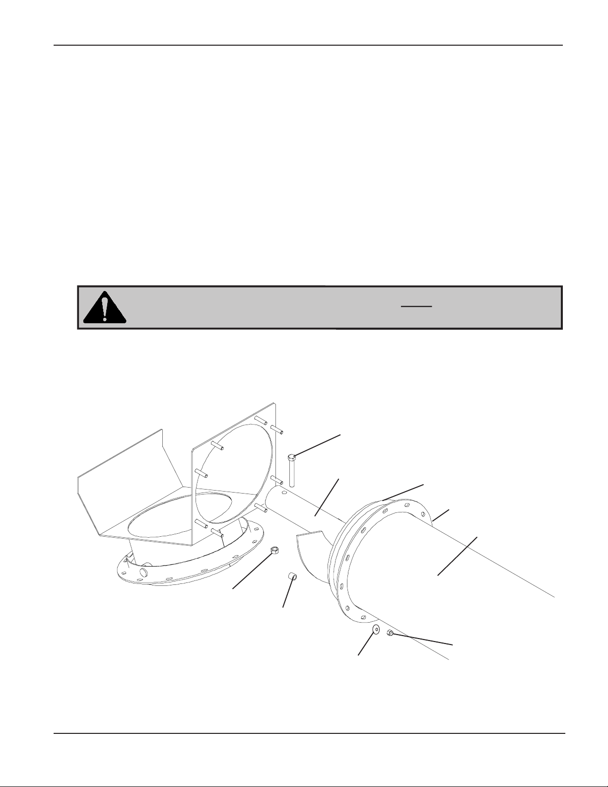
5. ASSEMBLE 8", 10", OR 12" INCLINE TUBE TO BUCKET ELEVATOR BOOT (See Figure 5)
A. Attach Transition* to B.E. Boot using 3/8"-16 x 1"
HHCS bolts, 3/8" lock washers, & 3/8"-16 Hex nuts.
B. Use a sling to lift the downspout end of the incline
tube assembly and position it directly over the transition opening.
C. Completely lower the tube until the spout flange
sits flat on top of the transition.
D. Install the spout flange to the top of the main inlet
hopper using four (4) 2" O.D. flat washers and 3/
8" nylon locknuts. The incline tube spout should
rotate on the top of the main inlet hopper.
*See next page for transition information.
22
Swivel Spout
Weldment
Tube
Weldment
3/8" Nylock
Nut
3/8"
Washer
Transition
3/8"-16 x 1 HHCS
3/8" Lock Washer
3/8" Hex Nut
Bucket Elevator Boot
PNEG-1391 8",10", & 12" BE-SAW Augers
Page 23

Assembly
Di
BE-SAW Transition
The GSI BESAW was designed to mate with GSI bucket elevators from 16" to 42" in size and capacities
from 1500 to 8000 BPH. Due to the large quantity of boot hoppers available for these bucket elevators, it
would be impossible for GSI to offer a transition assembly that would fit all the possible combinations of
BESAWs and bucket elevators. Since the BESAW requires special mounting components to swivel, after
April 1, 2006 each BESAW shipped from our facilities will include a BESAW Swivel Plate Assembly. The
swivel assembly is made up of a square plate with the attachment bolts welded to it. It already has the
appropriate sized hole bored in it to allow the flow of material. The swivel hardware is also included.
Swivel Plate Assembly
When fabricating the mounting transition, the top of this plate should be from 6" to 8" above the mounting
flange of the bucket elevator boot hopper. The center of the large hole should be a sufficient distance away
from the bucket elevator trunk to allow the BESAW chain guard to clear and the BESAW to swivel. An
example of a transition is shown below.
mension varies
due to the angle
of operation.
PNEG-1391 8",10", & 12" BE-SAW Augers
23
Page 24

Start-Up
1. DESIGNATE WORK AREA
A. Before starting the auger, establish the
designated work areas. Figure 6 below shows
where boundaries should be established.
B. Mark off the designated work areas using
colored nylon or plastic rope as portable
barriers.
RULES FOR SAFE WORK AREA
Under no circumstances should persons not
involved in the operation of the auger be
allowed to trespass into the designated work
area. It is the duty of ALL operators to
ensure that children and/or other persons
stay out of the work areas. Should anyone
not involved in the operation trespass into
the work area or into a hazard area, the
operator should immediately shutdown the
auger.
It is the responsibility of ALL operators to
ensure that the work area has secure
footing, and is clean and free of debris and
tools that might cause accidental tripping or
falling. The operator is also responsible for
keeping the work area clean and orderly
during operation of the auger.
Overhead Wires:
Keep Away!
Auger Intake
Area: Keep Out!
2. INSPECT THE AUGER
A. After your new auger is delivered and assem-
bly is complete, and before each use, you
must inspect the auger.
B. Be sure that ALL guards listed in the assem-
bly instructions are in place, secured, and functional.
Walking Surface: Is it
slippery? Are there things
that might trip you?
BE-SAW Auger
Wagon
or Truck
Work Area: Authorized
Personnel Only
FIGURE 6
C. Check ALL safety decals. Replace any that
are worn, missing, or illegible. A list of decals
found on the auger is included in the front of
this manual. You may obtain decals from your
dealer or order direct from the factory.
D. Ensure that ALL fasteners are tight.
24
E. Ensure that the inspection covers are in place.
PNEG-1391 8",10", & 12" BE-SAW Augers
Page 25

1. OPERATION RECOMMENDATIONS
Operation
A. One person must be in a position to monitor
the operation of the auger at ALL times. That
person should visually inspect the auger
before and during operation and be alert to
any unusual vibrations, noises, and the
loosening of any fasteners.
B. For smoother start-ups, keep the auger from
operating totally filled. This will also help
ensure efficient operation.
C. To avoid excessive wear, do not operate the
auger empty for any length of time.
D. You must “break-in" a screw conveyor when
it is new and at the beginning of each season.
Refer to Step 2 for instructions.
Be certain to close ALL the cleanout doors in the main auger head
before operating the auger.
The operator should not add
power before viewing the entire
work area and checking that ALL
personnel are clear of the designated work areas.
The operator should be alert to
any unusual vibrations or noises
that might indicate a need for
service or repair during the initial
start-up and break-in period.
The operator should regulate the
grain flow into the auger by controlling the amount of grain fed to
the hopper.
Be certain that ALL safety shields
and devices remain in place
during operation.
Ensure that hands, feet, and
clothing are kept away from moving parts.
Lockout the power source whenever the equipment must be
serviced or adjusted.
2. START-UP AND BREAK-IN
A. Any auger that is new or has set idle for a
season needs to go through a “break-in"
period.
B. Run the auger at partial capacity until several
hundred bushels of grain have been augered
and the flighting assembly and tube are
polished.
PNEG-1391 8",10", & 12" BE-SAW Augers
Do not stop or start the auger
under load because the auger has
a tendency to “freeze up," especially if the flight and tube have
not become well polished.
25
Page 26

Shutdown
1. NORMAL SHUTDOWN
A. Make sure that the hopper and auger are
empty before shutting down the unit.
B. Before the operator leaves the work area, the
power source should be locked out, as
described on below.
2. INTERMITTENT OPERATION SHUTDOWN
A. During intermittent operations such as batch
drying, give careful consideration to the size
of auger to use. Using a larger diameter auger
and reducing its load level is far better than
subjecting a smaller diameter auger to high
loads. An auger that is kept from absolute filling
will start-up easier and convey more efficiently.
3. EMERGENCY SHUTDOWN
WARNING: Precaution should be
made to prevent anyone from
operating the auger when the operator is absent from the work area.
The operator must stop the auger
and turn off the power source any
time he/she must leave the work
area, or service/adjust the auger.
IMPORTANT: Do not stop and
restart the auger when it is fully
loaded. This may damage the
auger.
A. If you have to immediately shutdown the auger
under load, be sure to disconnect and
lockout the power source.
B. Remove as much grain from the hoppers and
auger that you can before restarting.
C. Never attempt to restart the auger when it is
full.
D. When as much grain as possible has been
cleared from the hoppers and the auger,
reconnect the power source and clear the
remaining grain gradually.
4. LOCKOUT
A. To lockout the auger, stop the auger and turn
off the power supply.
B. The operator should lockout the SAW auger
in the following situations:
• Anytime the operator leaves the work
area, such as after shutdown.
• Anytime the operator services or adjusts
the auger.
IMPORTANT: Starting the auger
under load may result in damage to
the auger. Such damage is considered abuse of the equipment.
26
PNEG-1391 8",10", & 12" BE-SAW Augers
Page 27

1. LUBRICATION GUIDELINES
Maintenance
A. Check and service the auger frequently to
ensure economical and efficient operation of
your auger. Maintaining regular and correct
lubrication is key to proper maintenance. Infrequent or incorrect lubrication can result in
reduced efficiency, excessive wear, and needless downtime.
B. Refer to the drawing below to identify the parts
that need lubrication and the lubrication
frequency.
Lubrication Locations
Flexible Swing-Out Hopper U-Joints:
Lubricate 10 Hour Intervals
NEVER perform maintenance on the
auger unless all safety shields and
devices are in place. Replace any
that are damaged or lost. Do not
clean, adjust, or lubricate any part of
a machine that is in operation.
PNEG-1391 8",10", & 12" BE-SAW Augers
FIGURE 7
27
Page 28

Maintenance
2. FLEXIBLE SWING-OUT HOPPER FLIGHT U-JOINT LUBRICATION
A. A u-joint connects the hopper and the inclined
flight at the hopper elbow. Lubricate the flight
u-joint at approximately ten (10) hour intervals
using SAE multipurpose type grease.
B. To lubricate the u-joint, first remove the cover
strap.
C. Raise the hinged cover.
D. Lubricate the grease zerk if necessary.
E. Close the cover and replace the cover strap
before operating the unit.
Swing Out Hopper U-Joint Lubrication
WARNING: The hinge cover
must be closed and the strap
properly installed before
operating the unit.
Cover Strap
Hopper Flight
Bronze
Tail Flight
Bearing
3. MAIN AUGER HEAD BEARING
MAINTENANCE
A. The main auger head bearing is a self-
aligning, sealed ball bearing. It requires
lubrication daily during operation.
B. Although no adjustment needs to be made
to the bearing, ensure that it is firmly
fastened.
FIGURE 8
4. BRONZE FLIGHT BEARINGS MAINTENANCE
Hinged Cover
Incline Flight
Bronze Bearing
U-Joint
A. Bronze with graphite flight bearings support
the swing-away hopper flight. The bearings
require no lubrication.
B. If the bronze bearing spins inside the retainer,
replace it with a new one.
C. Remove the old bronze bearing and press in
the new one.
C. Be certain that the setscrews in the lock
collar are tight against the shaft, securing the
lock collar firmly to the shaft.
28
PNEG-1391 8",10", & 12" BE-SAW Augers
Page 29

Troubleshooting
Problem
1. THE AUGER IS
VIBRATING.
2. CAPACITY IS TOO LOW.
3. THE AUGER PLUGS.
Possible Cause
A. Damage can occur to the auger
flighting, causing noise. Damage
usually is caused from foreign
material being run through the
auger.
A. There may not be enough grain
reaching the auger.
B. The auger is moving too slowly.
A. The auger may be "jamming"
because too much grain is
reaching the auger.
Solution
A1. It may be necessary to remove
the flighting for inspection.
A1. Make sure the intake has not
bridged over, restricting flow.
The flighting at the intake should
be covered with grain for maximum capacity.
B1. Check the auger speed. Low
capacity will result from speeds
slower than recommended.
A1. Decrease the amount of grain the
auger is gathering.
4. DRIVELINE SHEAR BOLT
SHEARS FREQUENTLY.
B. The grain may be wet.
C. The auger may be jammed with
foreign material.
D. The discharge end may be
plugged.
A. Grain may be flowing too
quickly into the ground hopper.
B. The discharge of grain from the
main auger may be restricted.
B1. If wet grain or other hard-to-move
material is being augered,
reduce the amount of grain
being fed into the swing-away
hopper.
C1. Remove any foreign material in
the auger.
D1. Unplug any plugs at the
discharge end of the auger.
A1. Reduce the flow rate of grain into
the ground hopper.
B1. Inspect auger intake and
discharge areas for damage.
PNEG-1391 8",10", & 12" BE-SAW Augers
29
Page 30

Parts
8" & 10" BE-SAW HOPPER COMPONENTS
8" & 10" SWING A WAY HOPPER COMPONENTS
Ref # Part # Description
1 GK1490 Flexible Swing Away Hopper W eldment for 8"
GK1491 Flexible Swing Away Hopper Weldment for 10"
2 GK6484 Hopper Flight Weldment with Tail Stub for 8" (3/16" Flighting)
GK6485 Hopper Flight Weldment with Tail Stub for 8" (1/4" Flighting)
GK6487 Hopper Flight Weldment with Tail Stub for 10" (3/16" Flighting)
GK6488 Hopper Flight Weldment with Tail Stub for 10" (1/4" Flighting)
3 GK1360 Lid with Hinge for 8"
GK1361 Lid with Hinge for 10"
4 GK1560 Bearing Stub for 8" (1" x 7 1/4" Long)
GK1487 Bearing Stub for 10" (1 1/4" x 8" Long)
5 GK1357 Bearing Hanger Weldment with Bearing for 8" (1" Bore)
GK1359 Bearing Hanger Weldment with Bearing for 10" (1 1/4" Bore)
6 GK1362 Rubber Mat
7 GK1482 Rubber Mat Strap
8 GK1526 Hopper Wheel
9 GK1266 U-Joint for 8" (1" Bore x 5" Long)
GK1483 U-Joint for 10" (1 1/4" Bore x 5" Long)
10 GK1559 Incline Flight Tail Stub for 8" (1" x 6" Long)
GK1484 Incline Flight Tail Stub for 10" (1 1/4" x 5 3/4" Long)
11 GC10634 Tube - 08" x 116" Std Incline Tube Assembly
11 GK6968 Tube - 08" x 144" Std Incline Tube Assembly
11 GC10685 Tube - 10" x 120" Std Incline Tube Assembly
11 GC10445 Tube - 10" x 160" Std Incline Tube Assembly
12 GK6980 Screw - 08" x 7" Pitch x 9' 8"
12 GK6981 Screw - 08" x 7" Pitch x 12' 0"
12 GK6950 Screw - 10" x 9" Pitch x 10' 0"
12 GK6952 Screw - 10" x 9" Pitch x 13' 4"
15 GC10324 Swivel Spout W eldment for 8"
GC10385 Swivel Spout W eldment for 10"
17 GK1534 Rubber Sleeve for 8"
GK1535 Rubber Sleeve for 10"
18 GK2265 Cover Strap for 8"
GK1358 Cover Strap for 10"
19 GK1550 Incline Flight to Tail Stub-Stub Bolt Kit for 8"
GK1536 Incline Flight to Tail Stub-Stub Bolt Kit for 10"
30 PNEG-1391 8",10", & 12" BE-SAW Augers
Page 31

15
Parts
8" & 10" BE-SAW HOPPER COMPONENTS
6
18
3
22
23
12
11
22
10
7
5
8
9
4
8
22
2
24
24
17
1
8
8
12
Connecting Components
8" Standard Flight Mounted on 1.90" O.D. Tubing
10" Standard and Heavy Flighting Mounted on 2 3/8" O.D. Tubing
8" 10"
Ref. # Part # Part # Description
22 S-8316 -- Connecting Bolt 7/16"-14 x 3" HHCS Zinc YDP Gr 8 (8" Upper )
S-7249 -- Connecting Bolt 3/8"-16 x 3 " HHCS Zinc YDP Gr 5 (8" Lower )
-- S-8314 Connecting Bolt 1/2"-13 x 3-1/2 " HHCS Zinc Gr 8 (10" Upper)
-- S-9185 Connecting Bolt 7/16"-14 x 3-1/2 " HHCS Zinc YDP Gr 8 (10" Lower)
23 S-8317 S-8317 7/16"-14 ZN GrC Stover Type Locknut (10" Upper) & (8" Upper)
-- S-8315 1/2"-13 ZN GrC Stover Type Locknut (10" Upper)
S-7383 -- 3/8"-16 ZN Locknut (8" Lower)
24 S-248 -- 3/8" Flat Washer - USS Zinc GR2 (8" Lower)
-- S-8320 7/16" Flat Washer - USS Zinc (10" Lower)
31PNEG-1391 8",10", & 12" BE-SAW Augers
Page 32

Parts
12" BE-SAW HOPPER COMPONENTS
12" SWING A WAY HOPPER COMPONENTS
Ref No. Part No. Description
1 GK4255 Hopper
2 GK4256 Hopper Flight Weldment 3/16
GK4257 Hopper Flight Weldment 1/4"
3 GK4144 Lid w/Hinge
4 GK4254 Bearing Hanger Stub
5 GK4253 Bearing Hanger
N/S GK1303 Bronze Bushing 1.875" O.D. x 11/2" I.D. (in bearing hanger)
6 GK4289 Rubber Mat
7 GK4258 Rubber Mat Strap
8 GK1526 Rubber Wheel w/Steel Pin
9 GK1291 U-Joint (1 1/4" bore x 7") (12N)
10 GK4102 Shaft: Incline Flight Stub
11 Incline Tube Weldment
GC10574 Standard Tube 13' 3" Nominal
GC10577 Standard Tube 15' 3" Nominal
12 Incline Flight
GK7007 w/7ga Flighting X 15' Nominal
GK7008 w/7ga Flighting X 17' Nominal
15 GC10503 12" Swivel Spout W eldment
17 S-7509 W asher, Flat 1/2"
18 GK1535 Rubber Sleeve
19 S-8315 Nut, Lock 1/2-13
20 GK3833 Lid Cover Strap
21 S-8400 Bolt HHCS 1/2" - 13 x 3 3-4" Long Zinc Coated Grade 5
24 S-8251 Nut, Lock 3/8-16
25 GK4292 Spacer Bushing for Swivel Spout to Incline Tube
26 GK4147 Wheel: 8" Caster
32 PNEG-1391 8",10", & 12" BE-SAW Augers
Page 33

12" BE-SAW HOPPER COMPONENTS
8
26
Parts
12
21
10
7
1
2
5
4
9
26
18
17
19
11
6
6
3
20
15
Swing-Out Hopper Illustration
25
33PNEG-1391 8",10", & 12" BE-SAW Augers
Page 34

Parts
10" LOW-PROFILE HOPPER COMPONENTS
10" Low Profile Hopper Component
Ref. # Part # Description
1 GK5813 Swing Away Hopper with Bushing
2 GK5811 Flight 7" O.D. x 7 Ga.
GK5825 Flight 7" O.D. x 1/4".
3 GK5820 1" x 9" Intake Shaft
4 GK6954 1.25" x 60-15/16" Drive Shaft
5 GK5810 Hanger Bearing
6 GK1049 2 Hole Flange Bearing w/ 1" Bore & Lock Collar
7 GK1330 2 Hole Flange Bearing w/ 1.25" Bore & Lock Collar
8 GK1021 15 Tooth Sprocket 1.25" Bore
9 GK1110 22 Tooth Sprocket 1.00" Bore # 50 w/ Keyway
10 GK5821 Chain Guard
11 GK5900 Spacer Bushing 1.25" x .083" x .875"
12 GK1701 13 Tooth Idler Sprocket #50 x 5/8" Bore
14 GK6393 # 50 Roller Chain
13 GK5965 Spacer Bushing .843" x .109" x 1.00"
15 GK1483 U-Joint for 10" (1.25" bore x 5" long)
16 GK5857 Clevis Pin 5/8" x 9-3/4"
17 GK5817 Wheel 10" Dia. X 3.25" Wide
18 GK5815 Hopper Lid W eldment
19 GK5814 Lid Strap
20 GK5822 .125" x 6" x 161" Rubber Mat
21 GK1482 9.875" Rubber Mat Strap
22 GK5824 4.875" Rubber Mat Strap
23 GK6858 Screw - 10" X 9" Pitch x 10'-1 15/16"
24 GC10691 Tube - 10" x 120" Lo-Pro Incline Tube Assy
23 GK6959 Screw - 10" X 9" Pitch x 12'-10 15/16"
24 GC10437 Tube - 10" x 153" Lo-Pro Incline Tube Assy
25 GC10386 10" Swivel Spout Assembly
28 GK6394 Wheel Spacer Bus hing
34 PNEG-1391 8",10", & 12" BE-SAW Augers
Page 35

10" LOW-PROFILE HOPPER COMPONENTS
Parts
35PNEG-1391 8",10", & 12" BE-SAW Augers
Page 36

Parts
12" LOW-PROFILE HOPPER COMPONENTS
12" LOW PROFILE SWING A WAY HOPPER
Ref # Pa rt # Description
1 GK5813 Swing Away Hopper w/Bushing
2 GK5811 Flight 7" O.D. x 7 ga
GK5825 Flight 7" O.D. x 1/4"
3 GK5820 1" x 9" Intake Shaft
4 GK5812 1.25" x 57" Drive Shaft
5 GK5810 Hanger Bearing
6 GK1049 2 Hole Flange Bearing w/1" Bore & Lock Collar
7 GK1330 2 Hole Flange Bearing w/1.25" Bore & Lock Collar
8 GK1021 15 Tooth Sprocket 1.25" Bore
9 GK1014 15 Tooth Sprocket 1.00" Bore
10 GK5821 12" Chain Guard
11 GK5900 Spac er Bushing 1.25" x . 083" x .875"
12 GK5823 #50 Roller Chain
13 GK1701 13 Tooth Idler Sprocket #50 x 5/8" Bearing
14 GK5965 Spac er Bushing .843" x . 109" x 1.00"
15 GK5819 CV Joint 1.25" x 8.875"
16 GK5857 Clevis Pin 5/8" x 9 3/4"
17 GK5817 W heel 10" Dia x 3.25" W ide
18 GK5815 Hopper Lid W eldment
19 GK5814 Lid Strap
20 GK5822 .125" x 6" x 161" Rubber Mat
21 GK1482 9.875" Rubber Mat Strap
22 GK5824 4.875" Rubber May Strap
23 GK7007 12" Incline Flight Assembly 7 Ga. X 15' Nominal
GK7008 12" Incline Flight Assembly 7 Ga. X 17' Nominal
24 GC10580 12" Incline Tube Assembly 12' 8" Nominal
GC10583 12" Inc line Tube Assembly 14' 8" Nominal
25 GC10503 12" Swivel Spout Assembly
28 GK6394 W heel Spacer Bushing
36 PNEG-1391 8",10", & 12" BE-SAW Augers
Page 37

12" LOW-PROFILE HOPPER COMPONENTS
Parts
37PNEG-1391 8",10", & 12" BE-SAW Augers
Page 38

Parts
8" BE-SAW DRIVE COMPONENTS
Drive Components for BESAW
8" Auger
460 V & 220 V 60 Hz Operation
Capacity Item # Qty Description Specification Part No.
1 1 Motor - 182T 3hp/460V/3PH 60HZ 300-3
OR 1 Motor - 184T 3hp/220V/1PH 60HZ 300-1
2 4 Bolt-Hex Hd 3/8"-16 x 1 1/2" S-7515
3 4 Washer-Lock 3/8" Split S-1054
4 4 Nut-Hex 3/8-16 S-456
8 1 Key 1/4" sq x 3" S-8276
1450 BPH
1800 BPH
2200 BPH
2900 BPH
Capacity Item # Qty Description Specification Part No.
1450 BPH
1800 BPH
2200 BPH
2900 BPH
5 1 Sheave-Drv 2gr B 3.0"OD x 1 1/8" PT0563
6 1 Sheave-Drvn 2gr B 18.4"OD x sk GK2567
7 1 Bushing SK-1 1/4" GC07674
N/S 2 Belt BX65 MHC00743
5 1 Sheave-Drv 2gr B 3.0"OD x 1 1/8" PT0563
6 1 Sheave-Drvn 2gr B 1 5"OD x 1.25" GK1869
7 Not Used
N/S 2 Belt BX58 PT1179
5 1 Sheave-Drv 2gr B 3.0"OD x 1 1/8" PT0563
6 1 Sheave-Drvn 2gr B 12"OD x 1 1/4" GK1335
7 Not Used
N/S 2 Belt BX52 020-1034-6
5 1 Sheave-Drv 2gr B 4"OD x 1 1/8" 4018-2
6 1 Sheave-Drvn 2gr B 12"OD x 1 1/4" GK1335
7 Not Used
N/S 2 Belt BX54 MHC00949
380V 50 Hz Operation
1 1 Motor - 182T 3hp/380V/3PH 50HZ 300-3-50
2 4 Bolt-Hex Hd 3/8"-16 x 1 1/2" S-7515
3 4 Washer-Lock 3/8" Split S-1054
4 4 Nut-Hex 3/8-16 S-456
8 1 Key 1/4" sq x 3" S-8276
5 1 Sheave-Drv 2 GR A3.0B3.4-1210 MHC00760
Bushing 1210 - 1 1/8 MHC00144
6 1 Sheave-Drvn 2gr B 18.4"OD x sk GK2567
7 1 Bushing SK-1 1/4" GC07674
N/S 2 Belt BX65 MHC00743
5 1 Sheave-Drv 2 GR A3.0B3.4-1210 MHC00760
Bushing 1210 - 1 1/8 MHC00144
6 1 Sheave-Drvn 2gr B 1 5"OD x 1.25" GK1869
7 Not Used
N/S 2 Belt BX58 PT1179
5 1 Sheave-Drv 2 GR A3.0B3.4-1210 MHC00760
Bushing 1210 - 1 1/8 MHC00144
6 1 Sheave-Drvn 2gr B 12"OD x 1 1/4" GK1335
7 Not Used
N/S 2 Belt BX52 020-1034-6
5 1 Sheave-Drv 2 GR A4.0B4.4-1610 MHC01118
Bushing 1610 - 1 1/8 MHC00035
6 1 Sheave-Drvn 2gr B 12"OD x 1 1/4" GK1335
7 Not Used
N/S 2 Belt BX54 MHC00949
38 PNEG-1391 8",10", & 12" BE-SAW Augers
Page 39

10" BE-SAW DRIVE COMPONENTS
Drive Components for BESAW
10" Auger
460 V & 220 V 60 Hz Operation
Capacity Item # Qty Description Specification Part No.
1 1 Motor - 184T 5hp/460V/3PH 60HZ 500-3
OR 1 Motor - 184T 5hp/220V/1PH 60HZ 500-1
2 4 Bolt-Hex Hd 3/8"-16 x 1 1/2" S-7515
3 4 Washer-Lock 3/8" Split S-1054
4 4 Nut-Hex 3/8-16 S-456
8 1 Key 3/8" sq x 3" S-9181
4000 BPH
4600 BPH
5600 BPH
5 1 Sheave-Drv 2gr B 3.5"OD x 1 1/8" PT0567
6 1 Sheave-Drvn 2gr B 18.4"OD x sk GK2567
7 1 Bushing SK-1 1/2" GK4248
N/S 2 Belt BX66 MHC00616
5 1 Sheave-Drv 2gr B 4"OD x 1 1/8" 4018-2
6 1 Sheave-Drvn 2gr B 18.4"OD x sk GK2567
7 1 Bushing SK-1 1/2" GK4248
N/S 2 Belt BX66 MHC00616
5 1 Sheave-Drv 2gr B 4"OD x 1 1/8" 4018-2
6 1 Sheave-Drvn 2gr B 15"OD x 1 1/2" GK2567
7 Not Used
N/S 2 Belt BX60 MHC00028
Parts
380 V 50 Hz Operation
Capacity Item # Qty Description Specification Part No.
1 1 Motor - 184T 5hp/380V/3PH 50HZ 500.3-50
2 4 Bolt-Hex Hd 3/8"-16 x 1 1/2" S-7515
3 4 Washer-Lock 3/8" Split S-1054
4 4 Nut-Hex 3/8-16 S-456
8 1 Key 3/8" sq x 3" S-9181
4000 BPH
4600 BPH
5600 BPH
5 1 Sheave-Drv 2 GR A3.4B3.8-1610 MHC00499
Bushing 1610 - 1 1/8 MHC00035
6 1 Sheave-Drvn 2gr B 18.4"OD x sk GK2567
7 1 Bushing SK-1 1/2" GK4248
N/S 2 Belt BX66 MHC00616
5 1 Sheave-Drv 2 GR A4.0B4.4-1610 MHC01118
Bushing 1610 - 1 1/8 MHC00035
6 1 Sheave-Drvn 2gr B 18.4"OD x sk GK2567
7 1 Bushing SK-1 1/2" GK4248
N/S 2 Belt BX66 MHC00616
5 1 Sheave-Drv 2 GR A4.0B4.4-1610 MHC01118
Bushing 1610 - 1 1/8 MHC00035
6 1 Sheave-Drvn 2gr B 15"OD x 1 1/2" GK2567
7 Not Used
N/S 2 Belt BX60 MHC00028
39PNEG-1391 8",10", & 12" BE-SAW Augers
Page 40

Parts
12" BE-SAW DRIVE COMPONENTS
Drive Components for BESAW
12" Auger
460V 3PH 60Hz Operation
Ca pa city Ite m # Q ty De scription S pe cifi ca tion Pa rt No .
1 1 Motor - 213T 7 1/2hp/460V/3PH 60HZ 712-3
2 4 Bolt-Hex Hd 3/8"-16 x 1 1/2" S-7515
3 4 Washer-Lock 3/8" Split S -1054
4 4 Nut-Hex 3/8-16 S-456
8 1 Key 3/8" sq x 3" S-9181
7000 BPH 5 1 Sheave-Drv 3gr B 3.5"OD x 1 3/8" ID PT0588
6 1 Sheave-Drvn 3gr B 18.4"OD x SK GK 2570
7 1 B ushing S K -1 1/2" GK 4248
N/S 3 B elt B X73 017-1498-9
8000 BPH 5 1 Sheave-Drv 3gr A3.4B 3.8 SH GK6994
1 Bushing SH 1 3/8" GC07383
6 1 S heave-Drvn 3gr B 18.4"OD x SK GK 2570
7 1 B ushing S K -1 1/2" GK 4248
N/S 3 B elt B X73 017-1498-9
220V 1 PH 60 Hz Operation
Ca pa city Ite m # Q ty De scription S pe cifi ca tion Pa rt No .
1 1 M otor - 215 7 1/2hp/460V /3P H 60HZ 712-3
2 4 B olt-Hex Hd 3/8"-16 x 1 1/2" S-7515
3 4 W asher-Lock 3/8" Split S -1054
4 4 Nut-Hex 3/8-16 S-456
8 1 K ey 3/8" sq x 3" S -9181
7000 BPH 5 1 Sheave-Drv 3 GR 3.5"O.D. X 1 1/8" ID PT0587
6 1 S heave-Drvn 3gr B 18.4"OD x SK GK 2570
7 1 B ushing S K -1 1/2" GK 4248
N/S 3 B elt B X73 017-1498-9
8000 BPH 5 1 Sheave-Drv 3 GR A3.4B3.8 - SH GK 6994
1 Bushing Bushing SH x 1 1/8" Bore MHC00649
6 1 S heave-Drvn 3gr B 18.4"OD x SK GK 2570
7 1 B ushing S K -1 1/2" GK 4248
N/S 3 B elt B X73 017-1498-9
380V 3PH 50Hz Operation
Ca pa city Ite m # Q ty De scription S pe cifi ca tion Pa rt No .
1 1 M otor - 213T 7 1/2hp/380V/3PH 50HZ 712-3-50
2 4 B olt-Hex Hd 3/8"-16 x 1 1/2" S-7515
3 4 W asher-Lock 3/8" Split S -1054
4 4 Nut-Hex 3/8-16 S-456
8 1 K ey 3/8" sq x 3" S -9181
7000 BPH 5 1 Sheave-Drv 3 GR A3.6B4.0-1610 M HC00778
1 Bushing Bushing 1610 - 1 3/8 CE-00594
6 1 S heave-Drvn 3gr B 18.4"OD x SK GK 2570
7 1 B ushing S K -1 1/2" GK 4248
N/S 3 B elt B X73 017-1498-9
8000 BPH 5 1 Sheave-Drv 3 GR A4.2B4.6-1610 GC10714
Bushing 1610 - 1 3/8 CE -00594
6 1 S heave-Drvn 3gr B 18.4"OD x SK GK 2570
7 1 B ushing S K -1 1/2" GK 4248
N/S 3 B elt B X73 017-1498-9
40 PNEG-1391 8",10", & 12" BE-SAW Augers
Page 41

8", 10", & 12" BE-SAW DRIVE COMPONENTS
1
5
Parts
2
6
3
4
8
7
41PNEG-1391 8",10", & 12" BE-SAW Augers
Page 42

Parts
8" & 8" & 10" SWIVEL SPOUT COMPONENTS
8" Swivel Spout Assembly
Ref # Part # Qty. Description
1 GC10324 1 Swivel Spout Weldment
2 DC-1416 2 Danger Rotating Auger Decal
3 GC10340 2 Swivel Pin for Motor Mount 8 & 10"
4 GC10325 1 Motor Mount Plate
5 GC10338 1 Hinged Motor Mount Swing Adjuster
6 S-7835 2 Washer Flat 1" USS Zinc
7 S-240 2 Nut, Hex 1"-8 Zinc Grade 5
8 DC-1411 1 Decal - Shear Point
9 GK1017 1 Four Bolt Flange Bearing 1 1/4" w/Lock collar
10 GK1331 1 Shaft: Drive 1 1/4" x 10 1/2" Long
11 S-236 4 Lock Washer 1/2"
12 S-3729 4 Hex Nut 1/2"-13 Plated Grade 5
13 S-8312 4 Cotter Pin 3/16" dia x 1 1/2" Long
14 GK1571 1 Snap Fastener
15 S-8325 1 Screw MS #8 x 1/2 RHP ZN
16 S-6551 1 Washer Lock Split #8 Med ZN
17 S-6525 1 Nut Hex #8-32 ZN
10" Swivel Spout Assembly
Ref # Part # Qty. Description
1 GC10385 1 Swivel Spout Weldment
2 DC-1416 2 Danger Rotating Auger Decal
3 GC10340 2 Swivel Pin for Motor Mount 8 & 10"
4 GC10325 1 Motor Mount Plate
5 GC10338 1 Hinged Motor Mount Swing Adjuster
6 S-7835 2 Washer Flat 1" USS Zinc
7 S-240 2 Nut, Hex 1"-8 Zinc Grade 5
8 DC-1411 1 Decal - Shear Point
9 GK1343 1 Four Bolt Flange Bearing 1 1/2" w/Lock collar
10 GK1289 1 Shaft: Drive 1 1/2" x 11 1/2" Long
11 S-236 4 Lock Washer 1/2"
12 S-3729 4 Hex Nut 1/2"-13 Plated Grade 5
13 S-8312 4 Cotter Pin 3/16" dia x 1 1/2" Long
14 GK1571 1 Snap Fastener
15 S-8325 1 Screw MS #8 x 1/2 RHP ZN
16 S-6551 1 Washer Lock Split #8 Med ZN
17 S-6525 1 Nut Hex #8-32 ZN
42 PNEG-1391 8",10", & 12" BE-SAW Augers
Page 43

8" & 10" SWIVEL SPOUT COMPONENTS
Parts
12
10
11
4
3
9
1
7
6
5
6
7
3
13
14
2
8
15
16
17
43PNEG-1391 8",10", & 12" BE-SAW Augers
Page 44

Parts
12" SWIVEL SPOUT COMPONENTS
12" Swivel Spout Assembly
Ref # Part # Qty. Description
1 GC10502 1 Swivel Spout Weldment
2 DC-1416 2 Danger Rotating Auger Decal
3 GC10509 2 Swivel Pin for Motor Mount 12"
4 GC10504 1 Motor Mount Plate
5 GC10508 1 Hinged Motor Mount Swing Adjuster
6 S-7835 2 Washer Flat 1" USS Zinc
7 S-240 2 Nut, Hex 1"-8 Zinc Grade 5
8 DC-1411 2 Decal - Shear Point
9 GK2004 1 Four Bolt Flange Bearing 2" w/Lock collar
10 GK2006 1 Shaft: Drive 2" to 1 1/2" x 12" Long
N/S GC10419 1 Belt Guard (Not Shown)
12 S-8349 4 Hex Nut 5/8-11 Plated Grade 5
13 S-8312 4 Cotter Pin 3/16" dia x 1 1/2" Long
14 GK1571 1 Snap Fastener
15 S-8325 1 Screw MS #8 x 1/2 RHP ZN
16 S-6551 1 W asher Lock Split #8 Med ZN
17 S-6525 1 Nut Hex #8-32 ZN
44 PNEG-1391 8",10", & 12" BE-SAW Augers
Page 45

13
Parts
12" SWIVEL SPOUT COMPONENTS
5
4
7
6
6
7
3
10
3
2
14
9
8
15
16
12
17
1
45PNEG-1391 8",10", & 12" BE-SAW Augers
Page 46

Parts
BESAW SWIVEL ATTACHMENT PARTS
A swivel plate assembly is supplied with each BESAW
The swivel plate is used as the top plate of the customer supplied
transition assembly
8" BESAW 10" BESAW
Ref Part # Qty. Description Ref Part # Qty. Description
1 GC11649 1 Swvl Plt. Asy W/Bolt Kit 1 GC11645 1 Swvl Plt. Asy W/Bolt Kit
2 GC11646 1 Bolt Kit 2 GC11646 1 Bolt Kit
3 GC11650 1 Swvl Plt Weldment 3 GC11647 1 Swvl Plt Weldment
4 GK1532 4 3/8" Washer for Swivel 4 GK1532 4 3/8" Washer for Swivel
5 S-7383 4 3/8-16 Nylock Nut 5 S-7383 4 3/8-16 Nylock Nut
12" BESAW
Ref Part # Qty. Description
1 GC11652 1 Swvl Plt. Asy W/Bolt Kit
2 GC11646 1 Bolt Kit
3 GC11653 1 Swvl Plt Weldment
4 GK1532 4 3/8" Washer for Swivel
5 S-7383 4 3/8-16 Nylock Nut
Use the following hardware 6 S-7520
to attach the customer supplied 7 S-1054
transition to GSI bucket elevators 8 S-456
46 PNEG-1391 8",10", & 12" BE-SAW Augers
3/8"-16 x 1" HHCS
3/8" Lock Washer
3/8"-16 Hex Nut
Page 47

TRANSITION TO BUCKET ELEVATOR
Parts
5
4
3
6
7
8
47PNEG-1391 8",10", & 12" BE-SAW Augers
Page 48

Parts
10" BELT GUARD COMPONENTS
10" Belt Gua rd Parts
Ref. # Pa rt # Qty. Description
1 GC08972 1 Belt Guard Back Plate - 18" Sheave
2 GC04677 2 Hinge: .125" x 2" x .063" x 2" Bk
3 GC08983 1 Plast ic 18" Guard
4 DC-995 1 Decal - Warning Shear Point
5 DC-1379 1 Decal Notice
6 DC-994 1 Danger Shear Point
7 99-0026 2 Clip 1/4"-20 Tinnerman Nut
8 S-6674 2 Screw 1/4"-20 x 1/2" THS
9 S-7060 8 Rivet 3/16" x 1/2" (#64)
4
3
2
1
5
9
6
7
8
48 PNEG-1391 8",10", & 12" BE-SAW Augers
Page 49

Parts
HARDWARE LOCATION
CHARTS
49PNEG-1391 8",10", & 12" BE-SAW Augers
Page 50

Parts
HARDWARE LOCATION CHARTS
8" Std Profile BESAW
SAW BOP: 08" STD HPR GC10480
SAW, BOLT KIT: 08" STD HPR GC10481
GSI P/N Qty Description Where Used
PB-005 1 Bag Plastic 5" x 7" x 3 Mil.
S-7383 4 3/8-16 Nylock Nut Tube Ring to Head Assy
S-8317 2 Nut Stover 7/16-14 Zn Gr C Flight to Head Shaft
S-8316 2 Bolt HHCS 7/16 - 14 x 3 Zn GR8 Fli ght to Head Shaft
GK1534 4 Bus hing: Rubber 11/16x3/8x5/8"L Flight to Tail S haft
S-7383 2 Nut Nylock 3/8-16 Zn Gr 5 Flight to Tail Shaft
S-248 4 W asher Flat 3/8 USS Zn Flight to Tail S haft
S-
7249 2 Bolt HHCS 3/ 8-16 x 3 Zn GR5 Flight to Tail S haft
GK1559 1 Tail Shaft Flight to Tail Shaft
GK1526 3 Wheels Wheels to Hopper
S-858 9 W asher Flat 5/8" Wheels to Hopper
S-8312 3 Cotter Pin 3/16" x 1 1/2" lg Wheels to Hopper
GK1266 1 U-Joint U-Joint to t ail Shaft
S-7076 2 Bolt HHCS 5/16"-18 x 2 1/2" GR 5 U-Joint to tail Shaft
S-7382 2 Nut Nylock 5/16-18 U-Joint to tail Shaft
S-7534 2 Bolt HHCS 1/2" x 1 1/4" Screw Tube to Hopper
S-2121 4 W ashers Flat 1/2" Sc rew Tube to Hopper
S-8260 2 Nut Nylock 1/2"-13 Screw Tube to Hopper
GK1360 1 Hinged Cover Hinged Cover to Hopper
S-4275 2 Bolt HHCS 5/16-18 x 3/4" Hinged Cover to Hopper
S-845 2 W asher Flat 5/16 Hinged Cover to Hopper
S-7382 2 Nut Nylock 5/16-18 Hinged Cover to Hopper
GK2265 1 Cover Strap Cover Strap to Tube
S-7383 2 Nut Nylock 3/8"-16 Cover Strap to Tube
GK1362 1 Rubber Belting (151.5" LG) Rubber Belting to Hopper
GK1482 10 Attachment Clips Long Rubber Belting t o Hopper
S-6998 20 Bolt HHCS 1/ 4" x 1" Rubber Belting to Hopper
S-7025 20 Nut Nylock 1/4" Rubber Belting to Hopper
GK1482 10 Attachment Clips Long Rubber Belting t o Hopper
S-6998 20 Bolt HHCS 1/4" x 1" Rubber Belting to Hopper
S-7025 20 Nut Nylock 1/4" Rubber Belting to Hopper
50 PNEG-1391 8",10", & 12" BE-SAW Augers
Page 51

HARDWARE LOCATION CHARTS
10" Std Profile BESAW
SAW BOP: 10" STD HPR GC10454
SAW, BOLT KIT: 10" STD HPR GC10452
GSI P/N Qty Description Where Used
PB-005 1 Bag Plastic 5" x 7" x 3 Mil.
S-7383 4 3/8-16 Nylock Nut Tube Ring to Head Assy
S-8315 2 Nut Stover 1/2"-13 Zn Gr C Flight to Head Shaft
S-8314 2 Bolt HHCS 1/2"-13 x 3-1/2 Zn GR8 Flight to Head Shaft
GK1535 4 Bus hing: Rubber 7/8x1/2x5/8"L Flight to Tail Shaft
S-8317 2 Nut Stover 7/16-14 Zn Gr C Flight to Tail S haft
S-8320 4 W asher Flat 7/16 USS Zn Flight to Tail Shaft
S-9185 2 Bolt HHCS 7/16-14x3-1/ 2 Zn GR8 Flight to Tail Shaft
GK1484 1 Tail Shaft Flight to Tail Shaft
Parts
GK1526 3 Wheels Wheels to Hopper
S-858 9 W asher Flat 5/8" Wheels to Hopper
S-8312 3 Cotter Pin 3/16" x 1 1/2" lg Wheels to Hopper
GK1483 1 U-Joint U-Joint to t ail Shaft
S-7249 2 Bolt HHCS 3/8" x 3" GR 5 U-Joint to t ail Shaft
S-7383 2 Nut Nylock 3/8" U-Joint to tail Shaft
S-7534 2 Bolt HHCS 1/2" x 1 1/4" Screw Tube to Hopper
S-2121 4 W ashers Flat 1/2" Sc rew Tube to Hopper
S-8260 2 Nut Nylock 1/2"-13 Screw Tube to Hopper
GK1361 1 Hinged Cover Hinged Cover to Hopper
S-4275 2 Bolt HHCS 5/16-18 x 3/4" Hinged Cover to Hopper
S-845 2 W asher Flat 5/16 Hinged Cover to Hopper
S-7382 2 Nut Nylock 5/16-18 Hinged Cover to Hopper
GK1358 1 Cover Strap Cover Strap to Tube
S-7383 2 Nut Nylock 3/8"-16 Cover Strap to Tube
GK1362 1 Rubber Belting (151.5" LG) Rubber Belting to Hopper
GK1482 10 Attachment Clips Long Rubber Belting t o Hopper
S-6998 20 Bolt HHCS 1/4" x 1" Rubber Belting to Hopper
S-7025 20 Nut Nylock 1/4" Rubber Belting to Hopper
51PNEG-1391 8",10", & 12" BE-SAW Augers
Page 52

Parts
HARDWARE LOCATION CHARTS
10" Low Profile BESAW
SAW BOP: 10" Lo Pro HPR GC10455
SAW, BOLT KIT: 10" Lo Pro HPR GC10453
GSI P/N Qty Description Where Used
PB-005 1 Bag Plastic 5" x 7" x 3 Mil.
S-7383 4 3/8-16 Nylock Nut Tube Ring to Head Assy
S-8315 2 Nut Stover 1/2"-13 Zn Gr C Flight to Head Shaft
S-8314 2 Bolt HHCS 1/2"-13 x 3-1/2 Zn GR8 Flight to Head Shaft
GK1535 4 Bus hing:Rubber 7/8x1/2x5/8"L Flight to Tail Shaft
S-8317 2 Nut Stover 7/16-14 Zn Gr C Flight to Tail Shaft
S-8320 4 W asher Flat 7/16 USS Zn Flight to Tail Shaft
S-9185 2 Bolt HHCS 7/16-14x3-1/2 Zn GR8 Flight to Tail Shaft
GK1484 1 Tail Shaft Flight to Tail Shaft
GK5817 4 Wheels Wheels to Hopper
GK5857 4 Pin 5/8" x 9 3/4" lg W/.125 Hole Wheels to Hopper
S-7241 4 Cott er Pin 1/8 " x 1 1/ 4" lg Wheels to Hopper
GK6394 4 Bus hing:Whl Spcr;1.06x.125x.50 Wheels to Hopper
GK5819 1 U-Joint U-Joint to tail Shaft
S-7249 2 Bolt HHCS 3/8"-16 x 3" GR 5 U-Joint to tail Shaft
S-8251 2 Nut Stover 3/8"-16 U-Joint to tail Shaft
S-8760 2 Bolt HHCS 1/2"-13 x 1 1/2" Screw Tube to Hopper
S-2120 4 W ashers Flat 1/2" SAE Screw Tube to Hopper
S-8260 2 Nut Nyloc k 1/2"-13 Screw Tube to Hopper
GK5815 1 Hinged Cover Hinged Cover to Hopper
S-8072 3 Bolt HHCS 5/16-18 x 3/4" Hinged Cover to Hopper
S-1937 3 W asher Flat 5/16 Hinged Cover to Hopper
S-7382 3 Nut Nyloc k 5/16-18 Hinged Cover to Hopper
GK5814 1 Cover Strap Cover Strap to Tube
S-7383 2 Nut Nyloc k 3/8"-16 Cover Strap to Tube
GK5822 1 Rubber Belting (EA 161" lg) Rubber Belt ing t o Hopper
GK1482 10 Attachment Clips Long Rubber Belting to Hopper
GK5824 4 At tachment Clips Short Rubber Belting to Hopper
S-6998 28 Bolt HHCS 1/4" x 1" Rubber Belting t o Hopper
S-7025 28 Nut Nylock 1/4" Rubber Belting to Hopper
52 PNEG-1391 8",10", & 12" BE-SAW Augers
Page 53

HARDWARE LOCATION CHARTS
12" Low Profile BESAW
SAW BOP: 12" LOPRO HPR GC10587
SAW, BOLT KIT: 12" LOPRO HPR GC10588
GSI P/N Qty Description Where Used
GK5817 4 Wheels Wheels to Hopper
GK5857 4 Pin 5/8" x 9 3/4" lg W/. 125 Hole W heels t o Hopper
S-7241 4 Cotter Pin 1/8 " x 1 1/4" lg Wheels to Hopper
GK6394 4 Bus hing: Whl Spcr;1.06x.125x .50 Wheels to Hopper
GK5822 1 Rubber Belt ing (EA 161" lg) Rubber Belting to Hopper
GK1482 10 Attachment Clips Long Rubber Belting to Hopper
GK5824 4 At tachment Clips Short Rubber Belting to Hopper
S-6998 28 Bolt HHCS 1/4" x 1" Rubber Belting to Hopper
S-7025 28 Nut Nylock 1/4" Rubber Belting to Hopper
Parts
GK5815 1 Hinged Cover Hinged Cover to Hopper
S-8072 3 Bolt HHCS 5/16-18 x 3/4" Hinged Cover to Hopper
S-1937 3 W asher Flat 5/16 Hinged Cover to Hopper
S-7382 3 Nut Nylock 5/16-18 Hinged Cover to Hopper
GK5814 1 Cover Strap Cover Strap to Tube
S-7383 2 Nut Nylock 3/8"-16 Cover Strap to Tube
S-8760 2 Bolt HHCS 1/2"-13 x 1 1/2" S c rew Tube to Hopper
S-2120 4 W ashers Flat 1/2" SAE Screw Tube to Hopper
S-8260 2 Nut Nylock 1/2"-13 Screw Tube to Hopper
GK5819 1 U-Joint U-Joint to t ail Shaft
S-7249 2 Bolt HHCS 3/8"-16 x 3" GR 5 U-Joint to tail Shaft
S-8251 2 Nut Stover 3/8"-16 U-Joint to tail Shaft
GK1535 4 Bus hing: Rubber 7/8x1/2x5/8"L Flight to Tail Shaft
S-8315 2 Nut Stover 1/2-13 Zn Gr C Flight to Tail Shaft
S-2121 4 W asher Flat 1/2" Flight to Tail Shaft
S-8400 2 Bolt HHCS 1/2-13 X 3-3/4 Zn GR5 Flight to Tail Shaft
GK4102 1 Tail Shaft Flight to Tail Shaft
S-8606 2 Nut Stover 5/8"- 11 Zn Gr C Flight to Head Shaft
S-7011 2 Bolt HHCS 5/8"- 11 x 3-1/2 Zn GR8 Flight to Head Shaft
GK4292 8 Spac er Bus hing Tube Ring to Head Assy
S-7409 8 W asher Flat 3/8" Tube Ring to Head Assy
S-7383 8 3/8-16 Nylock Nut Tube Ring to Head Assy
PB-008 1 Bag Plastic 7" x 8" x 3 Mil.
53PNEG-1391 8",10", & 12" BE-SAW Augers
Page 54

Parts
HARDWARE LOCATION CHARTS
12" Low Profile BESAW
SAW BOP: 12" LOPRO HPR GC10587
SAW, BOLT KIT: 12" LOPRO HPR GC10588
GSI P/N Qty Description Where Used
GK5817 4 Wheels Wheels to Hopper
GK5857 4 Pin 5/8" x 9 3/4" lg W/.125 Hole Wheels to Hopper
S-7241 4 Cott er Pin 1/8 " x 1 1/ 4" lg Wheels to Hopper
GK6394 4 Bus hing:Whl Spcr;1.06x.125x.50 Wheels to Hopper
GK5822 1 Rubber Belting (EA 161" lg) Rubber Belt ing t o Hopper
GK1482 10 Attachment Clips Long Rubber Belting to Hopper
GK5824 4 At tachment Clips Short Rubber Belting to Hopper
S-6998 28 Bolt HHCS 1/4" x 1" Rubber Belting t o Hopper
S-7025 28 Nut Nylock 1/4" Rubber Belting to Hopper
GK5815 1 Hinged Cover Hinged Cover to Hopper
S-8072 3 Bolt HHCS 5/16-18 x 3/4" Hinged Cover to Hopper
S-1937 3 W asher Flat 5/16 Hinged Cover to Hopper
S-7382 3 Nut Nyloc k 5/16-18 Hinged Cover to Hopper
GK5814 1 Cover Strap Cover Strap to Tube
S-7383 2 Nut Nyloc k 3/8"-16 Cover Strap to Tube
S-8760 2 Bolt HHCS 1/2"-13 x 1 1/2" Screw Tube to Hopper
S-2120 4 W ashers Flat 1/2" SAE Screw Tube to Hopper
S-8260 2 Nut Nyloc k 1/2"-13 Screw Tube to Hopper
GK5819 1 U-Joint U-Joint to tail Shaft
S-7249 2 Bolt HHCS 3/8"-16 x 3" GR 5 U-Joint to tail Shaft
S-8251 2 Nut Stover 3/8"-16 U-Joint to tail Shaft
GK1535 4 Bus hing:Rubber 7/8x1/2x5/8"L Flight to Tail Shaft
S-8315 2 Nut Stover 1/2-13 Zn Gr C Flight to Tail Shaft
S-2121 4 W asher Flat 1/2" Flight to Tail Shaft
S-8400 2 Bolt HHCS 1/2-13 X 3-3/4 Zn GR5 Flight to Tail Shaft
GK4102 1 Tail Shaft Flight to Tail Shaft
S-8606 2 Nut Stover 5/8"- 11 Zn Gr C Flight to Head Shaft
S-7011 2 Bolt HHCS 5/8"- 11 x 3-1/2 Zn GR8 Flight to Head Shaft
GK4292 8 Spac er Bushing Tube Ring to Head Assy
S-7409 8 W asher Flat 3/8" Tube Ring to Head Assy
S-7383 8 3/8-16 Nylock Nut Tube Ring to Head Assy
PB-008 1 Bag Plastic 7" x 8" x 3 Mil.
54 PNEG-1391 8",10", & 12" BE-SAW Augers
Page 55

WARRANTY
THE COMPANY WARRANTS ALL PRODUCTS MANUFACTURED TO BE FREE OF DEFECTS IN MATERIAL
AND WORKMANSHIP UNDER NORMAL USAGE AND CONDITIONS FOR A PERIOD OF TWELVE (12)
MONTHS AFTER RETAIL SALE TO THE ORIGINAL END USER OF SUCH PRODUCTS. OUR ONLY
OBLIGATION IS, AND PURCHASER'S SOLE REMEDY SHALL BE TO REPAIR OR REPLACE, AT THE
COMPANY'S OPTION AND EXPENSE, PRODUCTS THAT, IN THE MANUFACTURERS SOLE JUDGEMENT,
CONTAIN A MATERIAL DEFECT DUE TO MATERIALS OR WORKMANSHIP. ALL DELIVERY AND SHIPMENT
CHARGES TO AND FROM THE FACTORY WILL BE PURCHASER'S RESPONSIBILITY. EXPENSES
INCURRED BY OR ON BEHALF OF THE PURCHASER WITHOUT PRIOR WRITTEN AUTHORIZATION
FROM AN AUTHORIZED EMPLOYEE OF THE COMPANY SHALL BE THE SOLE RESPONSIBILITY OF THE
PURCHASER.
EXCEPT FOR THE ABOVE EXPRESS LIMITED WARRANTIES, THE COMPANY MAKES NO WARRANTY
OF ANY KIND, EXPRESSED OR IMPLIED, INCLUDING, WITHOUT LIMITATION, WARRANTIES OF
MERCHANTABILITY OR FITNESS FOR A PARTICULAR PURPOSE OR USE IN CONNECTION WITH (i)
PRODUCT MANUFACTURED OR SOLD BY THE COMPANY OR (ii) ANY ADVICE, INSTRUCTION,
RECOMMENDATION OR SUGGESTION PROVIDED BY AN AGENT, REPRESENTATIVE OR EMPLOYEE
OF THE COMPANY REGARDING OR RELATED TO THE CONFIGURATION, INSTALLATION, LAYOUT,
SUITABILITY FOR A PARTICULAR PURPOSE, OR DESIGN OF SUCH PRODUCT OR PRODUCTS.
IN NO EVENT SHALL THE COMPANY BE LIABLE FOR ANY DIRECT, INDIRECT, INCIDENTAL, OR
CONSEQUENTIAL DAMAGES, INCLUDING, WITHOUT LIMITATION, LOSS OF ANTICIPATED PROFITS OR
BENEFITS. PURCHASER'S SOLE AND EXCLUSIVE REMEDY SHALL BE LIMITED TO THAT STATED
ABOVE, WHICH SHALL NOT EXCEED THE AMOUNT PAID FOR THE PRODUCT PURCHASED. THIS
WARRANTY IS NOT TRANSFERABLE AND APPLIES ONLY TO THE ORIGINAL PURCHASER. WE SHALL
HAVE NO OBLIGATION OR RESPONSIBILITY FOR ANY REPRESENTATIVE OR WARRANTIES MADE BY
OR ON BEHALF OF ANY DEALER, AGENT OR DISTRIBUTOR OF THE COMPANY.
THE COMPANY ASSUMES NO RESPONSIBILITY FOR FIELD MODIFICATIONS. MODIFICATIONS TO THE
PRODUCT NOT SPECIFICALLY COVERED BY THE CONTENTS OF THIS MANUAL WILL NULLIFY ANY
PRODUCT WARRANTY THAT MIGHT HAVE BEEN OTHERWISE AVAILABLE. THE USE OF OUR
EQUIPMENT TO HANDLE MATERIALS OTHER THAN FREE FLOWING, NONABRASIVE AND DRY
MATERIALS, AS INTENDED, WILL RESULT IN THE VOIDING OF THIS LIMITED WARRANTY.
THE FOREGOING WARRANTY SHALL NOT COVER PRODUCTS OR PARTS WHICH HAVE BEEN
DAMAGED BY NEGLIGENT USE, MISUSE, ALTERATION, OR ACCIDENT. ANY NEGLIGENT USE, MISUSE,
ALTERATION, OR DAMAGE DUE TO ACCIDENT, AS DETERMINED BY A COMPANY REPRESENTATIVE,
MAY VOID THE WARRANTY. THIS WARRANTY COVERS ONLY PRODUCTS MANUFACTURED BY THE
COMPANY. THIS WARRANTY IS EXCLUSIVE AND IN LIEU OF ALL OTHER WARRANTIES EXPRESS OR
IMPLIED. WE RESERVES THE RIGHT TO MAKE DESIGN OR SPECIFICATION CHANGES AT ANY TIME,
BEARING NO RESPONSIBILITY TO MAKE SIMILAR DESIGN OR SPECIFICATION CHANGES ON
PREVIOUSLY SOLD MERCHANDISE.
PRIOR TO INSTALLATION, PURCHASER HAS THE RESPONSIBILITY TO RESEARCH AND COMPLY WITH
ALL FEDERAL, STATE, AND LOCAL CODES WHICH MAY APPLY TO THE LOCATION AND INSTALLATION.
07/21/98
Page 56

This Equipment shall be installed in accordance
with the current installation codes and applicable
regulations which should be carefully followed in
all cases. Authorities having jurisdiction should be
consulted before installation occurs.
The GSI Group, Inc.
1004 E. Illinois St.
Assumption, IL 62510-0020
Phone: 217-226-4421
Fax: 217-226-4420
e-mail: gsisales@grainsystems.com
internet: http://www.grainsystems.com
Copyright © 2005 by The GSI Group
Printed in the USA
 Loading...