

Page 1

2300 Series Portable Dryer
Parts Manual
PNEG-1376
Page 2

Page 3

CONTENTS
Specifications.....................................................................................................................................................4
BOTTOM MODULE
Frame.................................................................................................................................................................5
Frame, Auger Trough, Hopper Bulkheads.........................................................................................................8
Meter Rolls......................................................................................................................................................10
Inside (Plenum) Screens, Plenum Closure Doors.............................................................................................12
Meter Roll Upper Shield Assembly..................................................................................................................13
Outside Screens, Meter Roll Access Door.........................................................................................................14
Plenum Divider................................................................................................................................................15
Clean Out Doors..............................................................................................................................................16
Module Support Pads, Stiffener Attach Angles................................................................................................18
Front Ladder Assembly....................................................................................................................................20
Rear Ladder Assembly..........................................................................................................................................21
Front End Panels, Fan Support, Grill Guards.....................................................................................................22
Rear End Panels, Rear Access Doors.................................................................................................................23
Bottom Auger...................................................................................................................................................24
Bottom Auger Drive........................................................................................................................................26
Meter Roll Drive..............................................................................................................................................28
TOP MODULE
Frame and Lower Basket..................................................................................................................................30
Inside (Plenum) Screens and Outside Screens....................................................................................................34
Stiffener Attach Angles and Crane Brackets......................................................................................................35
Front End Panels, Fan Support, Grill Guard, and Venturi................................................................................36
Rear End Panels, Rear Access Door, and Front and Rear Ladders....................................................................37
Top Auger with Wet Bin Assembly...................................................................................................................38
Top Auger Drive.................................................................................................................................................40
FAN HEATERS
Fan Housing Assembly.....................................................................................................................................42
Fan Motor, Motor Mount, and Fan Blade...........................................................................................................44
Air Mixer Assemblies........................................................................................................................................45
Flame Probe, Ignitor, and Burner Assemblies.....................................................................................................46
LP Pipe Train Assemblies..................................................................................................................................50
NG Pipe Train Assemblies................................................................................................................................54
Fan Heater Orifices.............................................................................................................................................57
LP Supply Lines.................................................................................................................................................58
NG Supply Lines....................................................................................................................................................60
ELECTRICAL (Bottom Module)
Plenum High Limit, Right Grain High Limit Thermostat...................................................................................62
Left Grain High Limit Thermostat, Operator Light.............................................................................................63
Lower Junction Box, Meter Roll Motor Conduit, Rear Discharge Conduit.........................................................64
Air Switch Assemblies........................................................................................................................................66
Network Control Box........................................................................................................................................67
ELECTRICAL (Top Module)
Lower Junction Box with Right and Left Grain High Limits.................................................................................68
Plenum High Limit..........................................................................................................................................69
Upper Junction Box, Top Auger Motor Conduit................................................................................................70
Wire Way Assembly..........................................................................................................................................71
ELECTRICAL (Fan Heater)
Vapor and Housing High Limit, and Solenoid Conduits.........................................................................................72
CONTROL BOXES
Fan Heater Control Box.....................................................................................................................................74
Control Box Switch Panel...................................................................................................................................76
Control Boxd Switch Panel (Rear).......................................................................................................................77
Lower Control Box Back Panel.............................................................................................................................78
Upper Control Box Panel......................................................................................................................................79
Notes.................................................................................................................................................................85
Page 4

SPECIFICATIONS
MODEL NUMBER
2314 2318 2320 2322 2326
Grain Columns
Top Auger (Loading)
Bottom Auger
(Unloading)
Meter Roll Drive
Transport Length
Transport Width
Transport Heigth*
Installed Length
Installed Width
Installed Height
Fan/Heaters
1 Ph
3 Ph
14” x 14’ long
8”, 5 hp
8” x 10” Tube
5 hp
14” x 18’ long 14” x 20’ long 14” x 22’ long 14” x 26’ long
8”, 5 hp 8”, 7.5 hp8”, 7.5 hp 8”, 10 hp
8” x 10” Tube
5 hp
8” x 10” Tube
7.5 hp
8” x 10” Tube
7.5 hp
8” x 10” Tube
10 hp
SCR, 3/4 hp SCR, 3/4 hp SCR, 3/4 hp SCR, 3/4 hp SCR, 3/4 hp
23’-2”
8’
13’-5” (11’-7”) 13’-5” (11’-7”) 13’-5” (11’-7”) 13’-5” (11’-7”) 13’-5” (11’-7”)
27’-2” 29’-2” 31’-2” 35’-2”
8’ 8’ 8’ 8’
20’-9” 24’-9” 26’-9” 28’-9” 32’-9”
8’ 8”
25’-11”
1 @ 10-17HP, 40”
2 @ 10-12HP, 28”
1 @ 15HP, 40”
2 @ 10-12HP, 28”
8’ 8” 8’ 8” 8’ 8” 8’ 8”
25’-11” 25’-11” 25’-11” 25’-11”
N/A N/A N/AN/A
1 @ 20HP, 42”
2 @ 10-12HP, 36”
1 @ 25HP, 42”
2 @ 15HP, 36”
1 @ 30HP, 42”
2 @ 15HP, 36”
1 @ 40HP, 42”
2 @ 25HP, 40”
* Shortest possible height shown in ().
Page 5
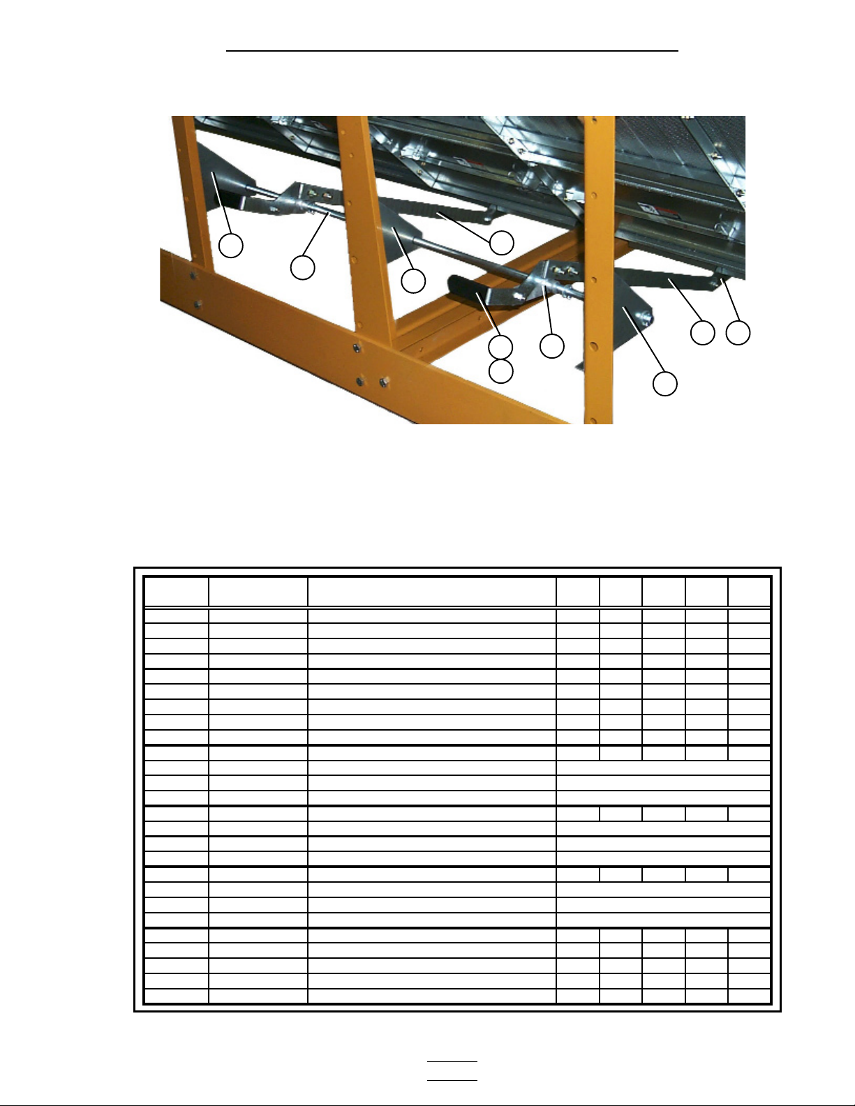
2300 Series Parts Manual Bottom Module
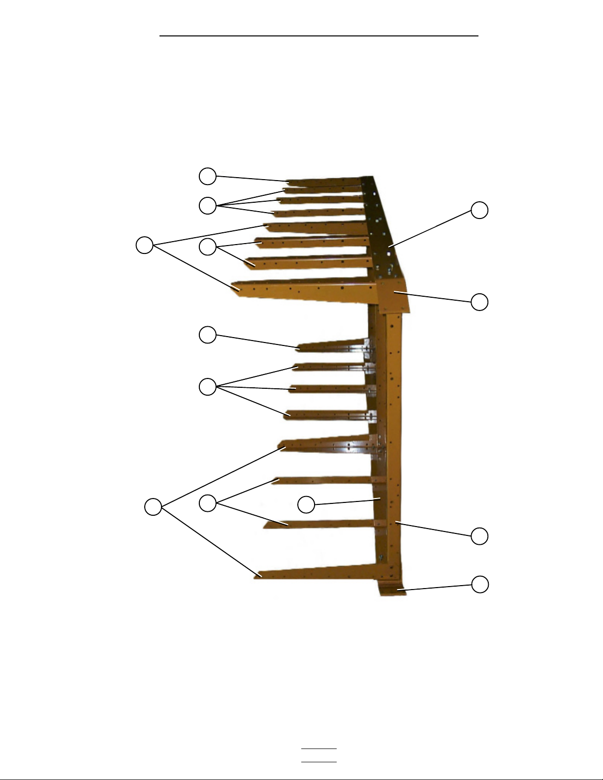
Frame
53
3
553
4a
3
5
4
Frame Assembly (view from fan/heater end with hitch weldment removed).
**NOTE: The parts pointed out on this page are listed on page 7.
- 5 -
Right side Left side
21a
1
The fan heater end of the dryer is considered by GSI as the front end of the dryer (the
foreground of this photograph is the front end. Right and left sides are labeled above).
Page 6
2300 Series Parts Manual Bottom Module
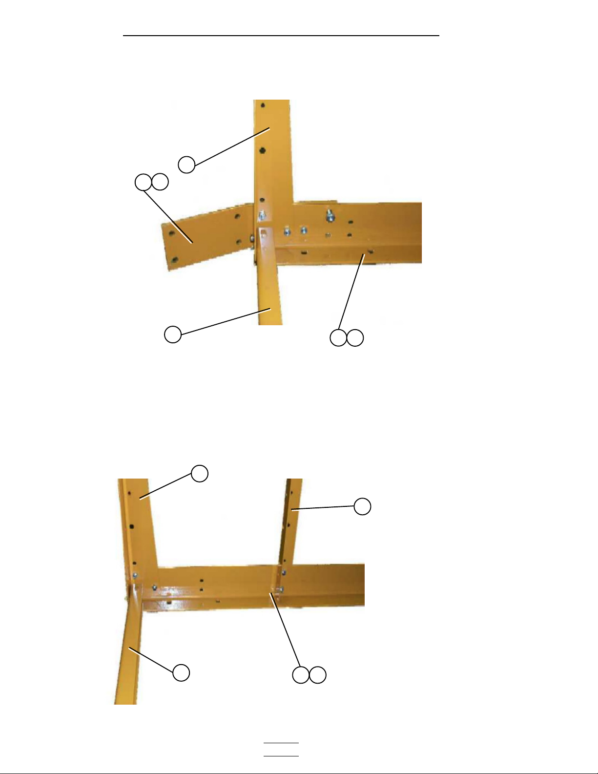
Right front corner of frame.
3
1
1a
Frame
**NOTE: The right front corner
is shown in the photo. For left
front corner all parts are the
same except for the Hitch
Bracket (use 1a for the left side),
and the Frame Rail (use 4a for
the left side).
2
Left rear corner of frame.
3
4a
4
5
**NOTE: The left rear corner is
shown in the photo. For right
rear corner all parts are the same
2
4a
4
except for the Frame Rail (use 4
for the right side).
- 6 -
Page 7
2300 Series Parts Manual Bottom Module
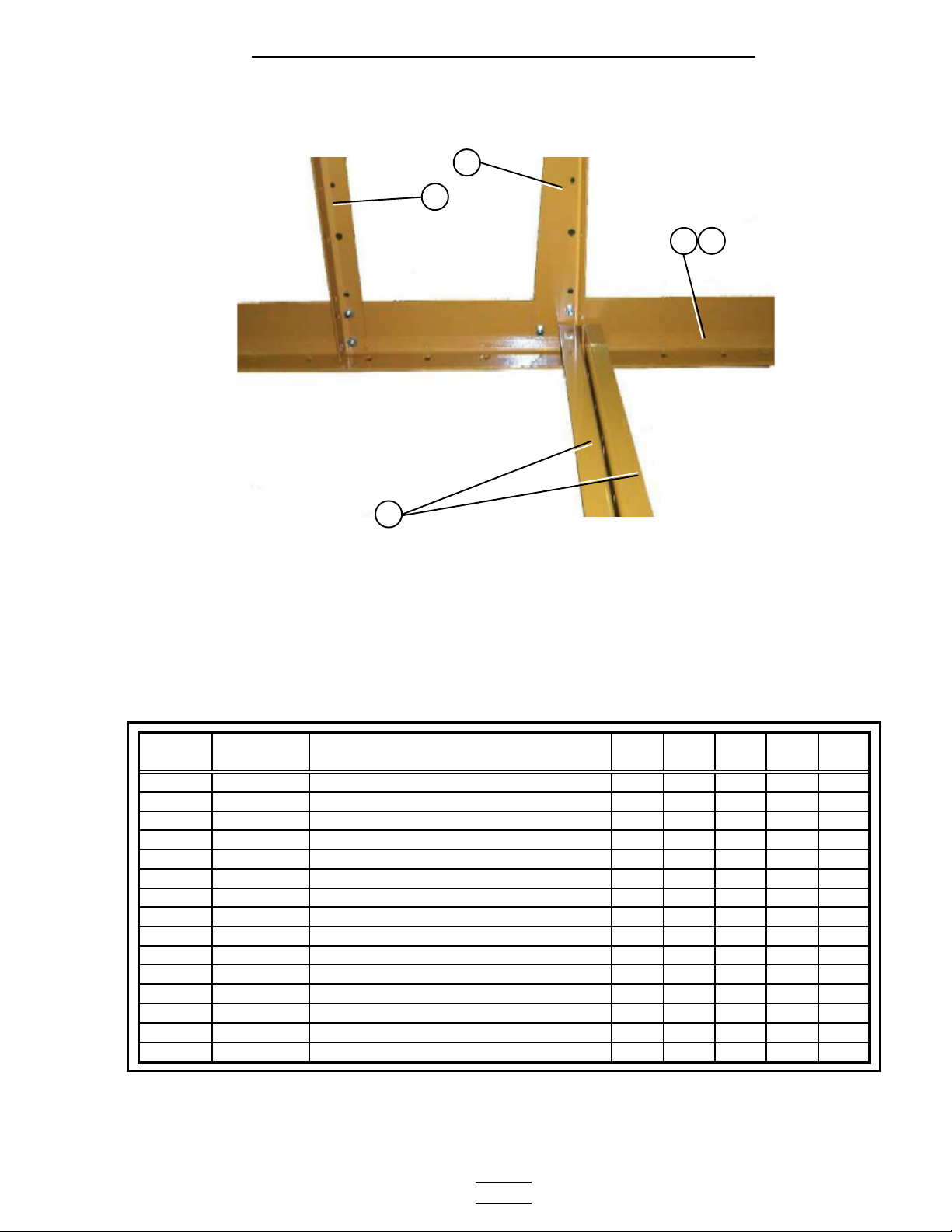
Center cross ties.
Frame
3
5
4a
4
2
ITEM
NUMBER
1 D01-0012 HITCH BRACKET RIGHT 1 1 1 1 1
1a D01-0011 HITCH BRACKET LEFT 1 1 1 1 1
2 D01-0008 FRONT & REAR FRAME TIE CHANNEL 4 4 4 6 6
3 D01-0007 CORNER LEG PORTABLE DRYER 6 6 6 8 8
4 D21-0011 FRAME RAIL, 14' RIGHT 1
4a D21-0010 FRAME RAIL, 14' LEFT 1
4 D31-0044 FRAME RAIL, 18' RIGHT 1
4a D31-0043 FRAME RAIL, 18' LEFT 1
4 D61-0002 FRAME RAIL, 20' RIGHT 1
4a D61-0001 FRAME RAIL, 20' LEFT 1
4 D101-0002 FRAME RAIL, 22' RIGHT 1
4a D101-0001 FRAME RAIL, 22' LEFT 1
4 D71-0001 FRAME RAIL, 26' RIGHT 1
4a D71-0002 FRAME RAIL, 26' LEFT 1
5 D01-0005 SIDE LEG PORTABLE DRYER 10 14 16 16 20
PART
NUMBER
DESCRIPTION 2314 2318 2320 2322 2326
- 7 -
Page 8
2300 Series Parts Manual Bottom Module
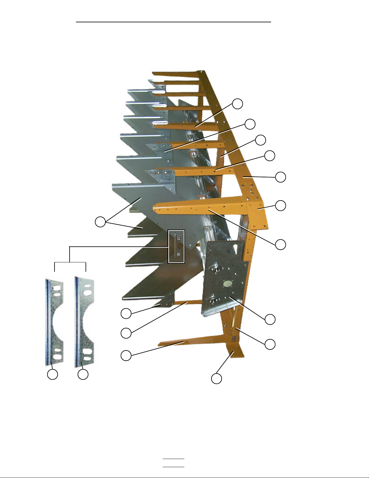
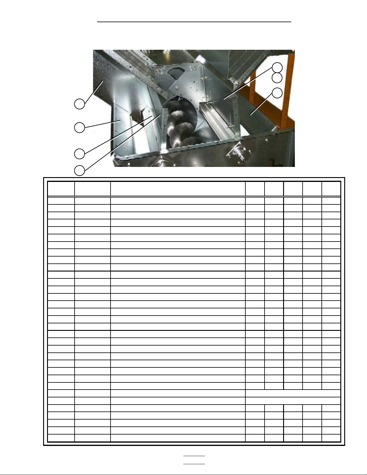
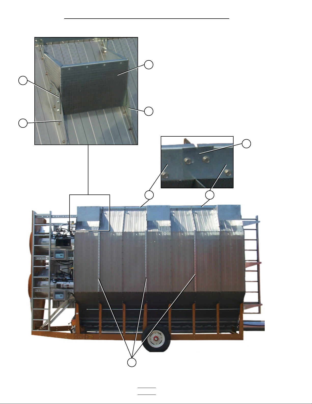
Frame / Auger Trough / Hopper Bulkheads
6
4
9
5
Dryer frame and lower basket assembly (view from the
front end of the dryer looking down the left side).
1
3
56 4
2
8 116
9 10
7
L.H. and R.H.
the plenum closure
distinguish between
door angles. This will
Note the hole pattern of
**NOTE: The parts pointed out on this page are listed on page 11.
- 8 -
Page 9
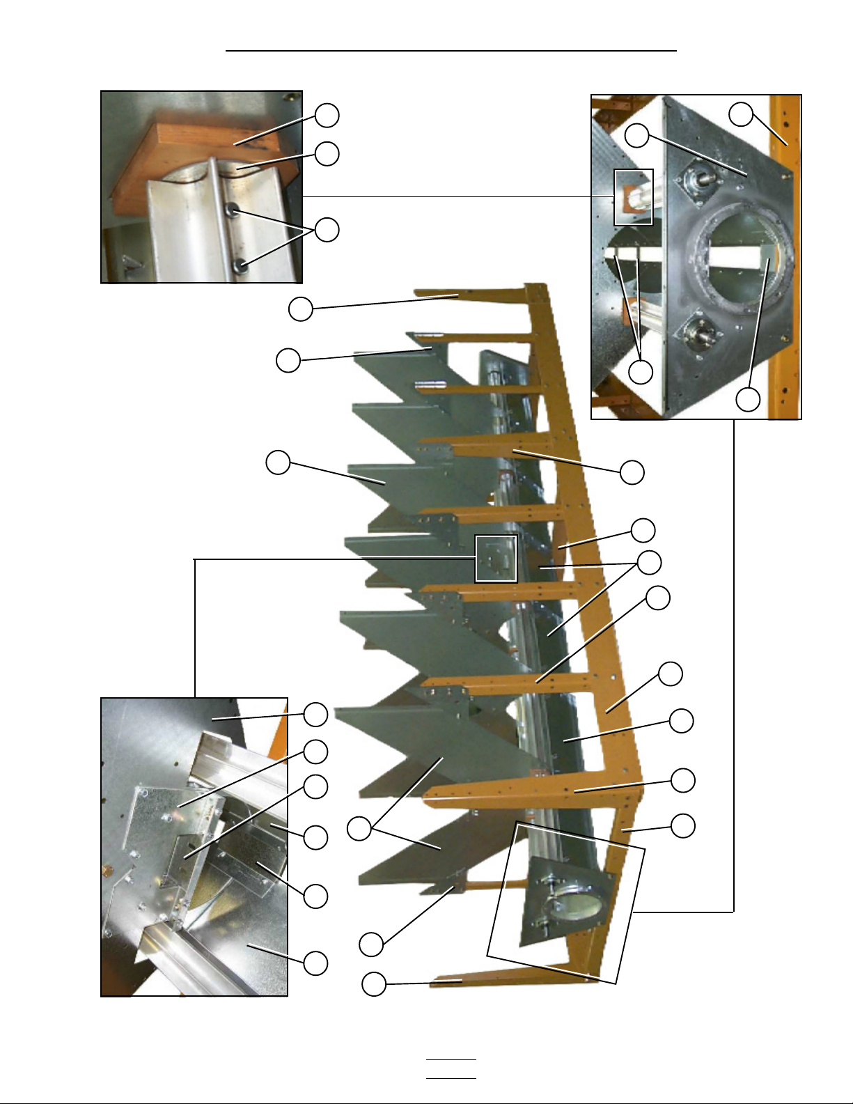
2300 Series Parts Manual Bottom Module
Frame / Auger Trough / Hopper Bulkheads
assembly.
shaft (part no. D31-0046) that
together with a meter roll splice
The meter roll sections are spliced
Wooden meter roll support bearing.
passes through the support bearing
181716
9
21
6
4
19
20
Discharge bearing plate.
3
6
Center hanger bearing support
and cross channel seal plate.
9
12
5
11a
12
3
9 6
4
12 13 12 14 15 3
6
**NOTE: The parts pointed out on this page are listed on page 11.
- 9 -
Dryer frame and lower basket assembly (view from the
rear end of the dryer looking up the right side).
Page 10
2300 Series Parts Manual Bottom Module
Meter Rolls and Their Placement in the Dryer
Metering Rolls and their placement in the dryer.
NOTE: Item 22 at the rear of
dryer is a front section meter
roll that is used as a rear section
on 16 and 20 foot dryers only.
22
24
Meter Roll Bearing
See pg. 11
Items 16, 17, 18
23
23
13
19
23
Meter Roll Bearing
See pg. 11
Items 16, 17, 18
23
Meter Roll Bearing
See pg. 11
Items 16, 17, 18
19
22
22
This end is the front (fan/heater) end of the dryer.
- 10 -
Page 11
2300 Series Parts Manual Bottom Module
Meter Rolls and Their Placement in the Dryer
ITEM
NUMBER
1 D01-1136Y PLENUM CLOSURE DOOR ANGLE, RH 6 8 9 10 12
2 D01-1136X PLENUM CLOSURE DOOR ANGLE, LH 7 9 10 11 13
3 D01-0109 HOPPER BULKHEAD 12 16 18 20 24
4 D01-0004 GUSSET PLATE 16 20 22 24 28
5 D01-0005 SIDE LEG 10 14 16 16 20
6 D01-0007 CORNER LEG 66688
7 D01-0011 HITCH BRACKET, LH 11111
8 D01-0012 HITCH BRACKET, RH 11111
9 D01-0008 FRONT & REAR FRAME TIE CHANNEL 44466
10 D01-1374 BOTTOM AUGER BEARING PLATE 11111
11 D21-0011 FRAME RAIL, 14' RIGHT 1
11 D31-0044 FRAME RAIL, 18' RIGHT 1
11 D61-0002 FRAME RAIL, 20' RIGHT 1
11 D101-0002 FRAME RAIL, 22' RIGHT 1
11 D71-0001 FRAME RAIL, 26' RIGHT 1
11A D21-0010 FRAME RAIL, 14' LEFT 1
11A D31-0043 FRAME RAIL, 18' LEFT 1
11A D61-0001 FRAME RAIL, 20' LEFT 1
11A D101-0001 FRAME RAIL, 22' LEFT 1
11A D71-0002 FRAME RAIL, 26' LEFT 1
12 D01-0048 TROUGH PANEL 14 18 20 22 26
13 D01-1512 PLATE, CROSS CHANNEL SEAL W/TABS 11122
14 D01-1291 HANGER BEARING "C" CHANNEL 11122
15 D01-1290 HANGER BEARING "J" PLATE 22244
16 D02-0028 CLEVIS PIN 5/16" x 1 3/4" 32 40 40 48 56
17 D31-0148 METER ROLL WASHER 16 20 20 24 28
18 D02-0061 METER ROLL SUPPORT BEARING 6 8 8 10 12
19 D01-0177 SUPPORT STRAP 7 9 10 11 13
20 D01-1511 PLATE, END CHANNEL SEAL W/TAB 22222
21 D31-0120 DISCHARGE PLATE 11111
22 D31-0031 METER ROLL, FRONT 22422
23 D31-0030 METER ROLL, INTERMEDIATE 466810
24 D31-0029 METER ROLL, REAR 2 2 2 2
PART
NUMBER
DESCRIPTION 2314 2318 2320 2322 2326
The part number list above covers all parts pointed out on pages 8, 9, and 10.
- 11 -
Page 12
2300 Series Parts Manual Bottom Module
Inside (Plenum) Screens / Plenum Closure Doors
Plenum screens and bulkheads (view from front end).
3
4
3
5
6
2
1
23
5
7
8
10
11
13
14
12
9
16
10
7
23
15
This photograph was taken before the front
plenum end panel and outer screens where
installed in order to get a good view of the inside
screens and bulkheads.
20
20a
21
22
Plenum closure door. There are two different plenum closure doors. The door
shown in the photogragh is the rear plenum closure door and is the rear most
plenum closure door, item no. 20 (just inside the rear access door), all others
are item no. 20a. NOTE: Item 22 is the plenum closure door rear frame angle.
- 12 -
Page 13
2300 Series Parts Manual Bottom Module
Meter Roll Upper Shield Assembly
Close up of of meter roll upper shield assembly.
16
17
18
19
19
18
17
ITEM
NUMBER
1 D31-0055 COLUMN BULK HEAD 12 16 18 20 24
2 D01-0101 GARNER BULKHEAD 12 16 18 20 24
3 D31-0307 COLUMN END PANEL 44444
4 D01-0126 SCREEN,PLENUM TOP,GA,094 14 18 20 22 26
5 D31-0012 SCREEN,PLENUM WALL,GA,094 14 18 20 22 26
6 D01-1225 SCREEN,PLENUM BOTTOM,GA,094 14 18 20 22 26
7 D01-0004 GUSSET PLATE 16 20 22 24 28
8 D21-0011 FRAME RAIL, 14' RIGHT 1
8 D31-0044 FRAME RAIL, 18' RIGHT 1
8 D61-0002 FRAME RAIL, 20' RIGHT 1
8 D101-0002 FRAME RAIL, 22' RIGHT 1
8 D71-0001 FRAME RAIL, 26' RIGHT 1
9 D21-0010 FRAME RAIL, 14' LEFT 1
9 D31-0043 FRAME RAIL, 18' LEFT 1
9 D61-0001 FRAME RAIL, 20' LEFT 1
9 D101-0001 FRAME RAIL, 22' LEFT 1
9 D71-0002 FRAME RAIL, 26' LEFT 1
10 D01-0007 CORNER LEG PORTABLE DRYER 66688
11 D01-0012 HITCH BRACKET RIGHT 11111
12 D01-0011 HITCH BRACKET LEFT 11111
13 D01-0008 FRONT & REAR FRAME TIE CHANNEL 44466
14 D01-1374 BOTTOM AUGER BEARING PLATE 11111
15 D01-0005 SIDE LEG PORTABLE DRYER 10 14 16 16 20
16 D01-0109 HOPPER BULKHEAD 12 16 18 20 24
17 D01-0050P CONNECTOR SHEET, PERFORATED 14 18 20 22 26
*18&19 D01-1180 METER ROLL UPPER SHIELD ASSY. 14 18 20 22 26
18 D01-0431 METER ROLL STRIKE OFF PLATE
19 D01-1226 METER ROLL SHIELD 1995 STYLE
20 D01-1214 PLENUM CLOSURE DOOR, REAR 11111
20a D01-1134 PLENUM CLOSURE DOOR 6 8 9 10 12
21 DC-974 DANGER FOOT IN AUGER DECAL 22222
22 D01-1217 PLENUM CLOSURE DOOR REAR FRAME ANGLE 11111
23 D61-0038 BULKHEAD STIFFENER BAR 24 32 36 40 48
PART
NUMBER
DESCRIPTION 2314 2318 2320 2322 2326
1 PER ASSEMBLY
1 PER ASSEMBLY
*ITEM NUMBERS 18 AND 19 TOGETHER MAKE UP THE METER ROLL UPPER SHIELD ASSEMBLY
- 13 -
Page 14
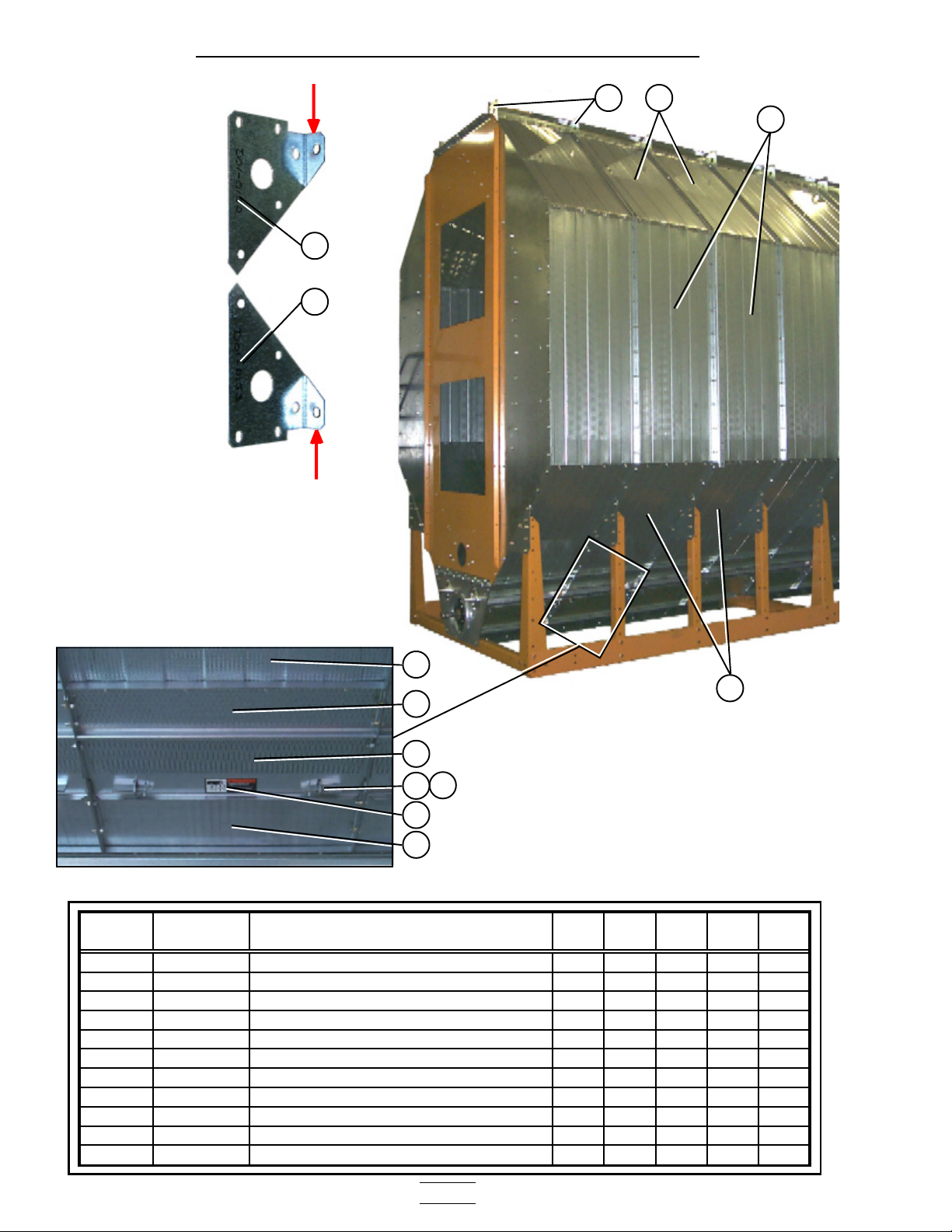
2300 Series Parts Manual Bottom Module
*Note: Item 4 is pointing to the
top edge angle gusset. There are
two types of gusset on the dryer.
The photo right will help
distinguish the difference
between the two. The arrows are
pointing to a tab on the gusset
that makes them different (tabs
are “bent” up in photo). Item 4a
is used in two places only; 1.)
front right of dryer 2.) rear left
of dryer, all others are item 4.
Outside Screens / Meter Roll Access Door
4
*
4
4a
1
2
Meter roll access door.
ITEM
NUMBER
1 D01-0127 SCREEN,ROOF,GA,094 14 18 20 22 26
2 D31-0013 SCREEN,OUTSIDE WALL,GA,094 14 18 20 22 26
3 D01-0128 SCREEN,HOPPER,GA,094 14 18 20 22 26
4 D01-0152 LH TOP ANGLE GUSSET 12 16 18 20 24
4a D01-0153 RH TOP ANGLE GUSSET 22222
5 D01-0050P CONNECTOR SHEET, PERFORATED 14 18 20 22 26
6 D01-0045P ACCESS DOOR, PERFORATED 14 18 20 22 26
7 D01-0039 DOOR LATCH 28 36 40 44 52
8 S-6552 PIN HAIR CLIP 3/32 ZN PLATED 28 36 40 44 52
9 DC-1229 DECAL, WARNING METER ROLL ROT. 14 18 20 22 26
10 D01-0048 TROUGH PANEL WELDMENT 14 18 20 22 26
PART
NUMBER
3
3
5
6
8
7
9
10
DESCRIPTION 2314 2318 2320 2322 2326
- 14 -
Page 15
2300 Series Parts Manual Bottom Module
Plenum Divider
Right rear plenum divider section with clean-out door.
1
2
3
2
Plenum divider support channels.
ITEM
NUMBER
1 D31-0259 PLENUM DIVIDER CLEAN-OUT DOOR 1 1 1 1 1
2 D31-0260 CLEAN-OUT DOOR GUIDE PLENUM 2 2 2 2 2
3 D61-0028 PLENUM DIVIDER RH: REAR 1 1 1 1 1
4 D61-0024 PLENUM SUPPORT CHANNEL 8 10 11 12 14
5 D61-0026 PLENUM DIVIDER RH 6 8 9 10 12
6 D61-0025 PLENUM DIVIDER LH 6 8 9 10 12
7 D61-0027 PLENUM DIVIDER LH: REAR 1 1 1 1 1
PART
NUMBER
Plenum divider floor sections.
4
5
DESCRIPTION 2314 2318 2320 2322 2326
7
6
4
- 15 -
Page 16
2300 Series Parts Manual Bottom Module
Clean Out Doors
Front and rear handle mechanisms (rear shown in photo).
1
3
2
4
5
13
*Note: Items 9, 10, & 11 together create the
clean out door assembly. There are three
different clean out door assemblies that are used
on GSI Network dryers:
1.) 3 column clean out door assy. (D51-0077).
Item 8a on the part no. listing (pg 17).
2.) 4 column clean out door assy. (D11-0032).
Item 8b on the part no. listing (pg 17).
3.) 5 column clean out door assy. (D01-0349).
Item 8c on the part no. listing (pg 17).
A 5 column clean out door assy (D01-0349) is
shown in the photograph below.
11
Clean out door handle mechanism.
4
3a
3
2
Clean out door hinge.
5
9
6
7
11
10
9
10
12
11
13
11
- 16 -
Page 17
2300 Series Parts Manual Bottom Module
Clean Out Doors
Center handle mechanisms (this handle mechanism stradles the center cross channels).
14
3a
1a
14
3a 11
4
2
5
14
ITEM
NUMBER PART NUMBER
1 D01-0264 PIVOT ROD 25.188" 22222
1a D31-0162 PIVOT ROD 49.625" 11122
2 D01-0296 LINKAGE BAR WELDMENT 44466
3 D01-0261 LINKAGE BAR, 37" LONG 22222
3a D01-0293 LINKAGE BAR, 30" LONG 22244
4 D01-0294 CLEAN OUT DOOR HANDLE 44466
5 S-4378 PLASTIC GRIP 44466
6 S-248 WASHER, FLAT 3/8 USS ZN 8 8 8 12 12
7 S-7241 COTTER PIN, 1/8 x 1 1/4 8 8 8 12 12
8a D51-0077 CLEAN OUT DOOR ASSY, 3 COLUMN 1 1
9 D21-0005 CLEAN OUT DOOR, 67"
10 D21-0012 SUPPORT CHANNEL, CLEAN OUT DOOR
11 D01-0308 CLEAN OUT DOOR HINGE
8b D11-0032 CLEAN OUT DOOR ASSY, 4 COLUMN 1 1 2 2
9 D31-0021 CLEAN OUT DOOR, 91"
10 D31-0130 SUPPORT CHANNEL, CLEAN OUT DOOR
11 D01-0308 CLEAN OUT DOOR HINGE
8c D01-0349 CLEAN OUT DOOR ASSY, 5 COLUMN 1 2 1
9 D01-0180 CLEAN OUT DOOR, 115"
10 D01-0307 SUPPORT CHANNEL, CLEAN OUT DOOR
11 D01-0308 CLEAN OUT DOOR HINGE
12 D01-0175 HINGE BRACKET 45667
13 D01-0181 CLEAN OUT EXTENSION, 119.75" 2 4 2
13 D31-0023 CLEAN OUT EXTENSION, 90.75" 2 2 4 4
13 D21-0006 CLEAN OUT EXTENSION, 66.75" 2 2
14 D01-0299 PIVOT ROD BRACKET 33366
DESCRIPTION 2314 2318 2320 2322 2326
1 PER ASSEMBLY
1 PER ASSEMBLY
2 PER ASSEMBLY
1 PER ASSEMBLY
1 PER ASSEMBLY
2 PER ASSEMBLY
1 PER ASSEMBLY
1 PER ASSEMBLY
3 PER ASSEMBLY
- 17 -
Page 18
2300 Series Parts Manual Bottom Module
Module Support Pads / Stiffener Attach Angles
Module support pad.
8
See page 19 for column locations for the
upper module base pads and stiffener attach
7
6
5
angles.
Top edge angle splice.
2
1 3
4
- 18 -
Page 19
2300 Series Parts Manual Bottom Module
Module Support Pads / Stiffener Attach Angles
ITEM
NUMBER
1 D21-0003 TOP EDGE ANGLE 71.875" 2 2
1 D31-0004 TOP EDGE ANGLE 95.875" 4
1 D01-0168 TOP EDGE ANGLE 119.875" 2 4
2 D31-0003 TOP EDGE ANGLE SPLICE 2 2 2 4 4
3 D31-0004 TOP EDGE ANGLE 95.875" 2 2 4
3 D01-0168 TOP EDGE ANGLE 119.875" 2
4 D01-0872 STIFFENER ATTACH ANGLE 6 8 10 10 12
5 D61-0021 BODY TIE-IN GUSSET LH 6 8 8 8 10
6 D61-0022 BODY TIE-IN GUSSET RH 6 8 8 8 10
7 D61-0012 CRANE BRACKET 4 4 4 4 4
8 D61-0013 MODULE SUPPORT PAD 6 8 8 8 10
PART
NUMBER
Dark lines shows the
column location for the
stiffener attach angles.
DESCRIPTION 2314 2318 2320 2322 2326
X shows the column
location for the pad
base for the upper
module.
- 19 -
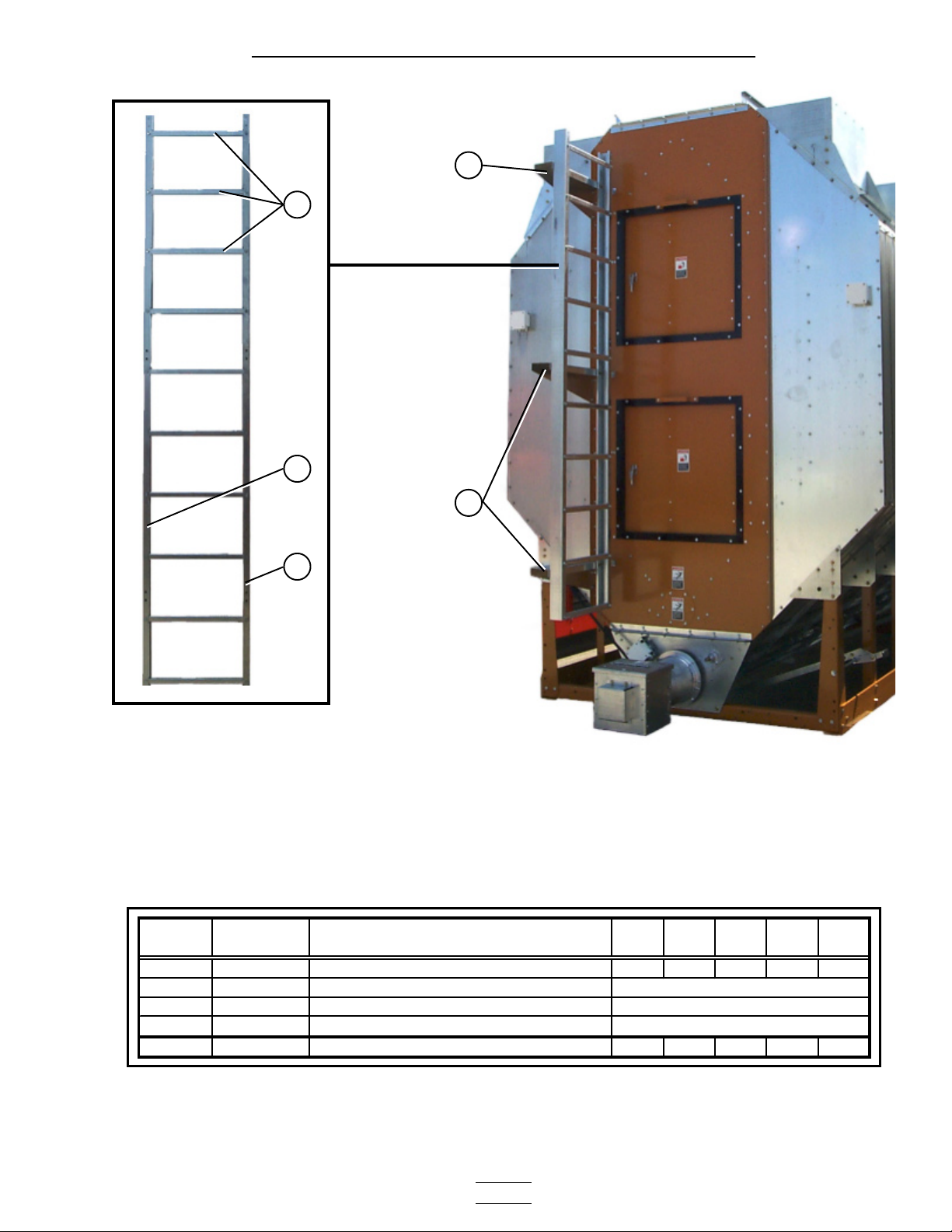
Page 20
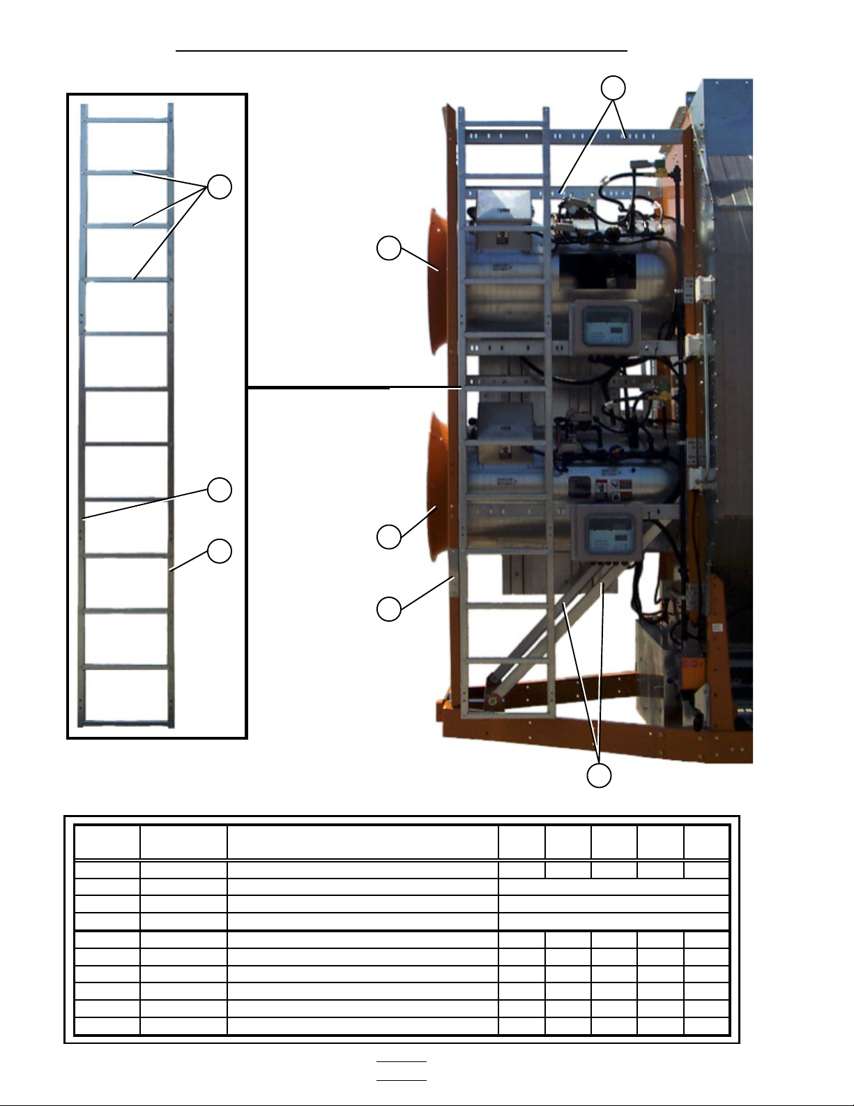
2300 Series Parts Manual Bottom Module
Front Ladder Assembly
1
5
4
2
5
3
6
7
ITEM
NUMBER
1-3 D01-1220 LADDER ASSY. STACK DRYER FRONT 1 1 1 1 1
1 D61-0096 LADDER RUNG
2 D61-0094 LADDER SIDE RAIL-TOP MODULE LH
3 D61-0095 LADDER SIDE RAIL-TOP MODULE RH
4 D51-0022 SUPPORT, CONTROL PANEL 7 7 7 7 7
5 F-7060-Y VENTURI: 28" YEL/OCHRE 2
5 CD-0543-Y VENTURI: 36" OCHRE 2 2 2
5 CD-0545-Y VENTURI: 40" OCHRE 2
6 D51-0021 STIFFENER, FRONT FAN SUPPORT 2 2 2 2 2
7 D31-0082 FRONT DIAGONAL SUPPORT CHANNEL 2 2 2 2 2
PART
NUMBER
DESCRIPTION 2314 2318 2320 2322 2326
12/ASSEMBLY
1/ASSEMBLY
1/ASSEMBLY
- 20 -
Page 21
2300 Series Parts Manual Bottom Module
Rear Ladder Assembly
4
1
2
4
3
ITEM
NUMBER
1-3 D04-0388 LADDER ASSEMBLY 1 1 1 1 1
1 D61-0096 LADDER RUNG
2 D61-0092 LADDER SIDE RAIL-LH
3 D61-0093 LADDER SIDE RAIL-RH
4 D61-0097 LADDER MOUNTING BRACKET, REAR 3 3 3 3 3
PART
NUMBER
DESCRIPTION 2314 2318 2320 2322 2326
10/ASSEMBLY
1/ASSEMBLY
1/ASSEMBLY
- 21 -
Page 22
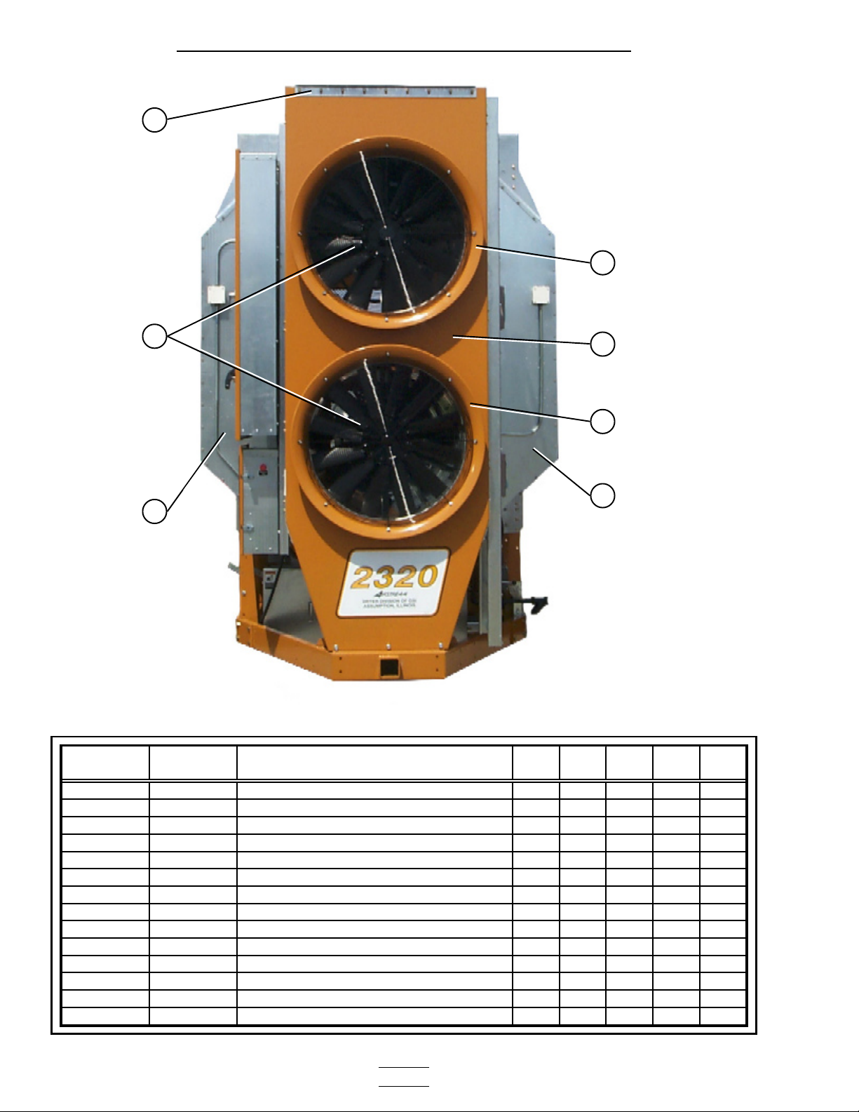
2300 Series Parts Manual Bottom Module
Front End Panels / Fan Support / grill guards
1
5
2
3
4
5
3
ITEM
NUMBER
1 D61-0023TOP ANGLE, FAN SUPPORT PANEL 11111
2 CD-0576 GRILL GUARD: CD-28 BLACK 2
2 CD-0544 GRILL GUARD: 36" BLACK 2 2 2
2 CD-0547 GRILL GUARD: 40&42" BLACK 2
3 D31-0307COLUMN END PANEL 44444
4 D01-0593 FRONT FAN SUPPORT 2-28" 1
4 D61-0041 FRONT FAN SUPPORT 2-36" 1 1 1
4 D71-0008 FRONT FAN SUPPORT 2-40" 1
5 F-7060-Y VENTURI: 28" YEL/OCHRE 2
5 CD-0543-Y VENTURI: 36" OCHRE 2 2 2
5 CD-0545-Y VENTURI: 40" OCHRE 2
NOT SHOWN D01-0594 FRONT END PANEL 2-28" 1
NOT SHOWN D61-0018 FRONT END PANEL 2-36" 1 1 1
NOT SHOWN D71-0006 FRONT END PANEL 2-40" 1
PART
NUMBER
DESCRIPTION 2314 2318 2320 2322 2326
- 22 -
Page 23
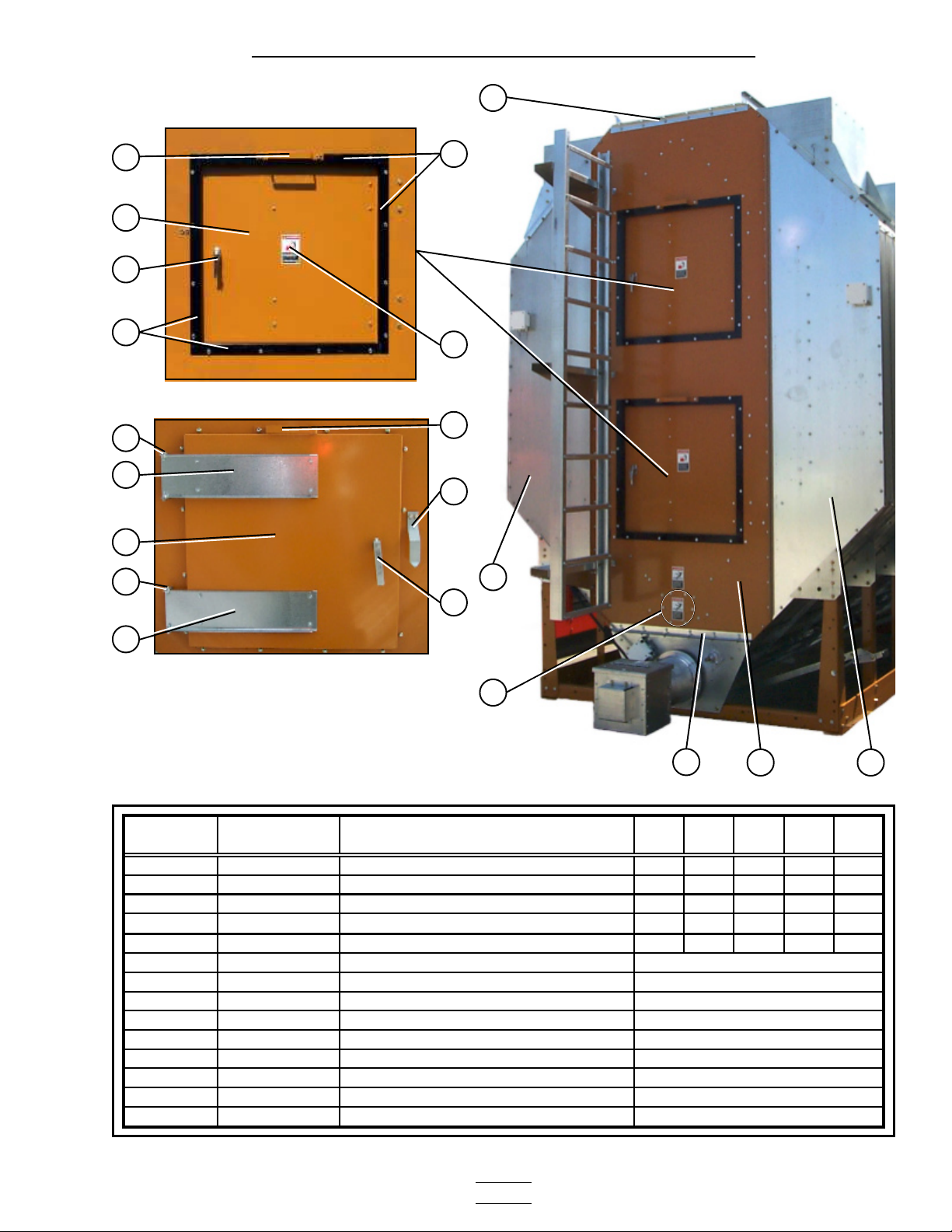
2300 Series Parts Manual Bottom Module
Rear End Panels / Rear Access Door
Rear access door (outside).
3
5
6
7
8
Rear access door (inside).
10
11
6
10
8
9
5
12
1
13
11
4
3
ITEM
NUMBER PART NUMBER
1 D31-0307COLUMN END PANEL 44444
2 D01-1800-YREAR END PANEL 50/50 29" DOORS11111
3 D01-0044TOP ANGLE BRACKET FRONT & REAR33333
4 D01-1510ASPIRATOR END CAP 11111
5-13 RDA-29-YREAR DOOR ASSEMBLY 29"SQ OCHR 22222
5 D01-1783-Y ASSIST HANDLE 29" SQ. DOOR
6 D01-1781-Y DOOR 29" SQUARE OCHRE
7 D03-0512 DOOR HANDLE,LOCKING CCW
8 D01-1782-BLK FRAME ANGLE 29" DOOR
9 DC-973 DECAL, DANGER FIRE HAZARD
10 401-4630-0 HINGE BRACKET-SQUARE DOOR
11 401-4669-8 HINGE-REAR ACCESS SQ DOOR
12 D01-0397 LATCH BRACKET
13 D01-1792 LATCH BAR 29" SQUARE DOOR
DESCRIPTION 2314 2318 2320 2322 2326
2 1
2/ASSEMBLY
1/ASSEMBLY
1/ASSEMBLY
4/ASSEMBLY
2/ASSEMBLY
2/ASSEMBLY
2/ASSEMBLY
1/ASSEMBLY
1/ASSEMBLY
- 23 -
Page 24
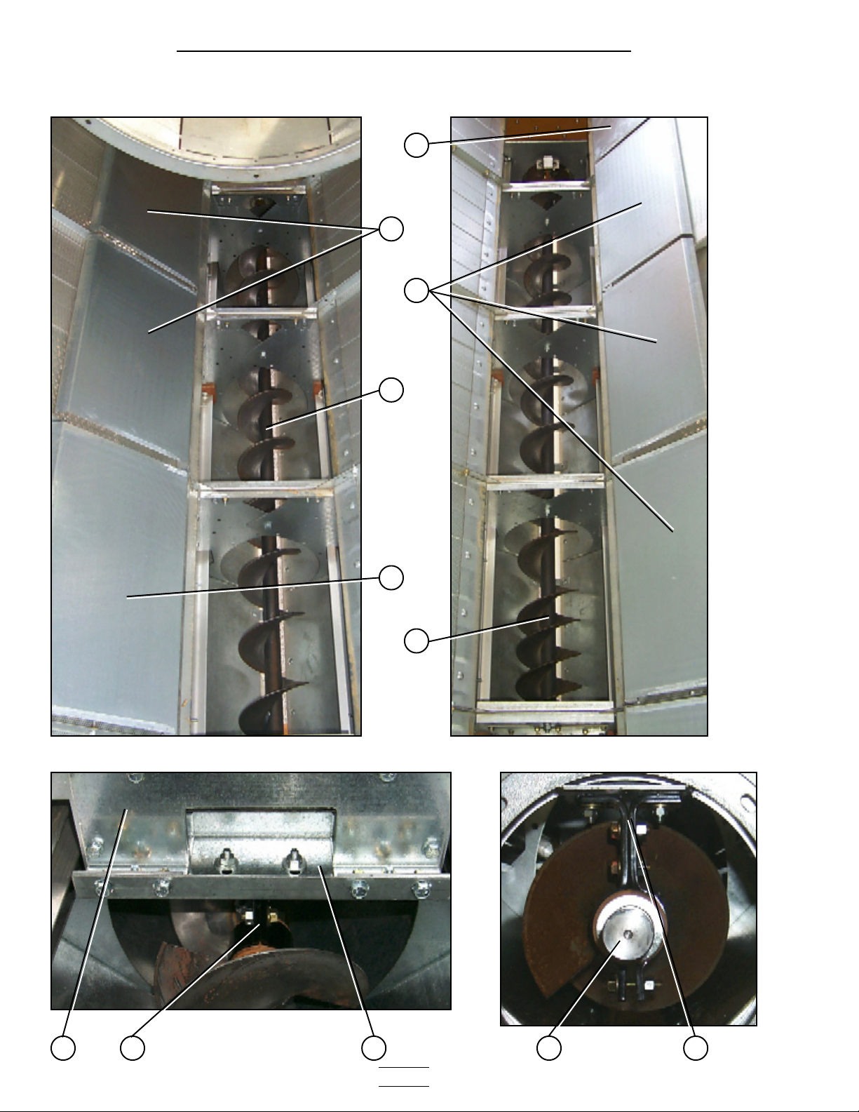
2300 Series Parts Manual Bottom Module
Bottom Auger (view from center of dryer to
the forward end).
Bottom Auger
Bottom Auger (view from center of dryer to
the rear end).
1
2
2
3
2
4
Bottom Auger center bearing and support. Bottom Auger rear bearing.
- 24 -
8 75 7 6
Page 25
2300 Series Parts Manual Bottom Module
Bottom Auger
Rear Discharge Box. Auger bearing.
18 19
17
20
9
10
16
11
12
ITEM
NUMBER PART NUMBER
1 D01-1214 PLENUM CLOSURE DOOR, REAR 11111
2 D01-1134 PLENUM CLOSURE DOOR 6 8 9 10 12
3 D21-0017 AUGER BOTTOM FRONT WELDMENT 1 1
3 D31-0092 AUGER BOTTOM FRONT WELDMENT 1 1
3 D31-0092 AUGER BOTTOM FRONT WELDMENT (116 3/8" LONG) 1
4 D31-0267 AUGER BOTTOM REAR WELDMENT 1 1 2 2
4 D61-0184 AUGER BOTTOM REAR WELDMENT (117 7/8" LONG) 1
5 D01-1290 HANGER BEARING BOTTOM J-PLATE 22244
6 D01-1291 HANGER BEARING BOTTOM C-CHANNEL 11122
7 D01-1246 HANGER BEARING ASSEMBLY (SHORT) 22233
8 D31-0076 SHAFT, AUGER SPLICE 22233
9-19 D01-0481-MS DISCHARGE BOX ASSEMBLY 11111
9 D01-1884 DISCHARGE WELDMENT
10 D01-1886 MOIST. SAMPLER TUBE COVER PLATE
11 D01-0405 GRAIN SAMPLER ASSEMBLY
12 D01-1752 DISCHARGE SIDE COVER
13 D01-1751 DISCHARGE SICE PANEL MC
14 D31-0298 DISCHARGE SIDE PANEL
15 D01-1885 MOIST. SAMPLER COVER PLATE
16 D01-1650 REAR AUGER BEARING SHIELD
17 D31-0299 DISCHARGE BOX BEARING PLATE
18 D01-0466 DISCHARGE TOP PANEL
19 D01-0467 DISCHARGE TOP FLAPPER
20 D32-0001 FLANGETTE BEARING 11111
21 D31-0005 SHAFT, TOP &BOT AUGER STUB 11111
NOT SHOWN D31-0079 DISCHARGE AUGER WELDMENT 11111
13 14 15
DESCRIPTION 2314 2318 2320 2322 2326
21
1/ASSEMBLY
1/ASSEMBLY
1/ASSEMBLY
1/ASSEMBLY
1/ASSEMBLY
1/ASSEMBLY
1/ASSEMBLY
1/ASSEMBLY
1/ASSEMBLY
1/ASSEMBLY
1/ASSEMBLY
- 25 -
Page 26
2300 Series Parts Manual Bottom Module
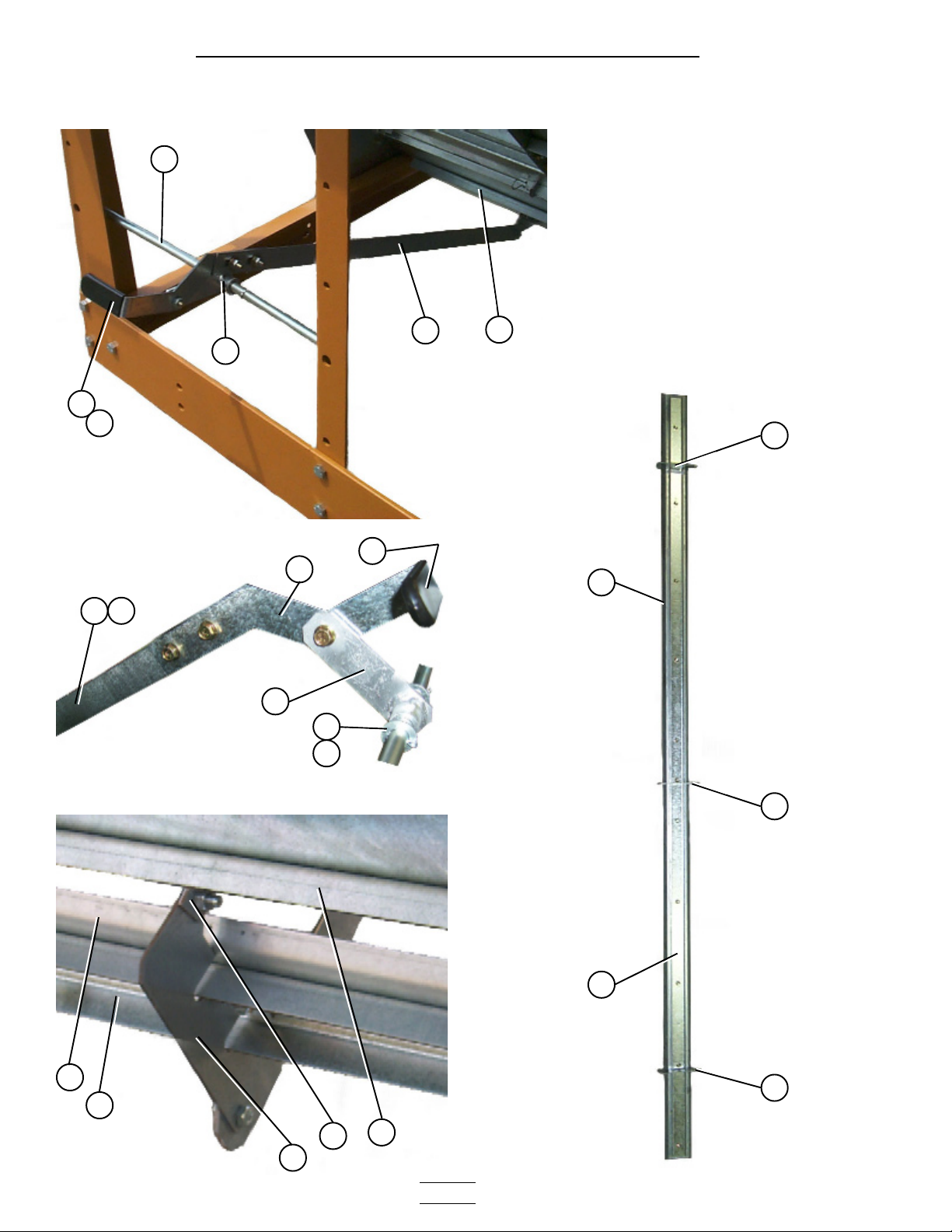
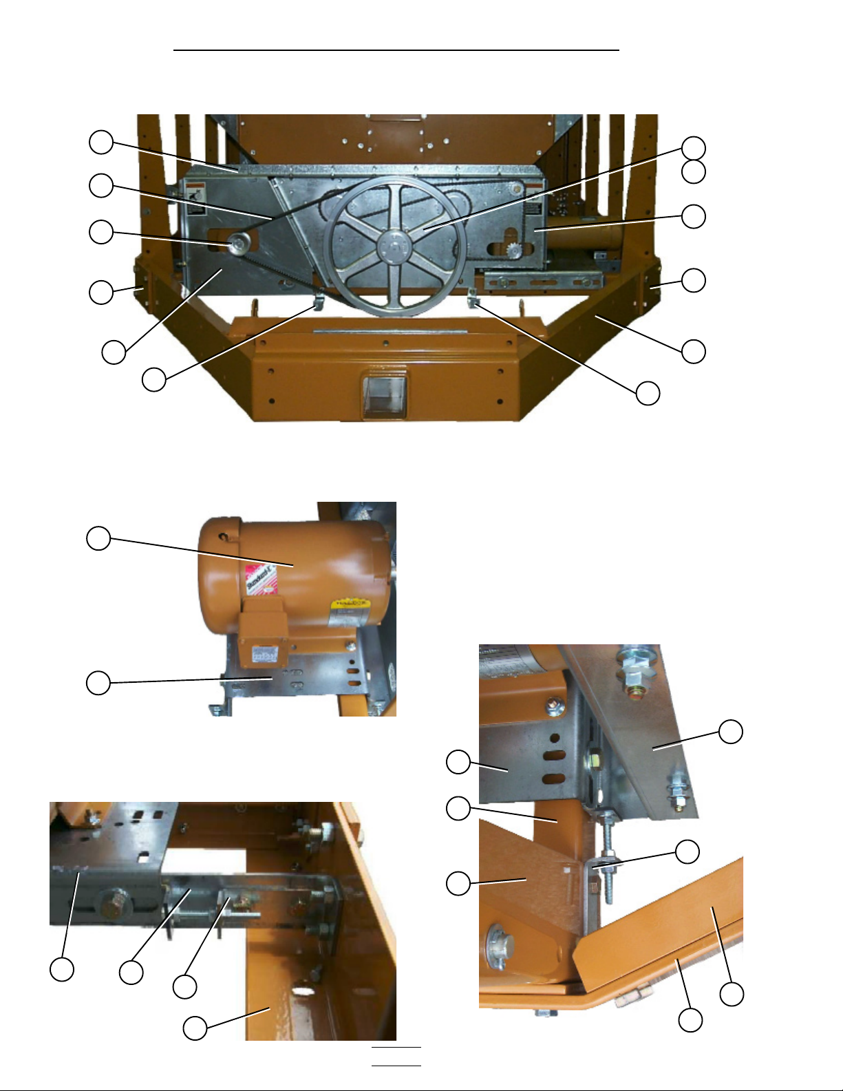
Bottom Auger Drive
Bottom Auger drive components
12
1
2
3
4
5
11
Bottom Auger motor and motor mount.
9
10
8
7
6
11
13
Rear drive tension adjustment.
13
18
16
17
Forward drive tension adjustment.
5
13
14
16
15
6
4
- 26 -
Page 27
2300 Series Parts Manual Bottom Module
Bottom Auger Drive
Bottom auger and metering roll drive guard.
21
19
20
22
ITEM
NUMBER
1 D01-1376 BOTTOM FRONT ANGLE BRACKET 11111
2 MHC00490 BELT-V BX82 22222
3 2818-2 SHEAVE 2GR 3.35Dx1 1/8" 1 1
3 D62-0003 SHEAVE 2GR 4.25Dx1 3/8" 1 1 1
4 D01-0012 HITCH BRACKET, RIGHT 11111
5 D01-1373 BELTGUARD, UNLOAD MOTOR SHROUD 11111
6 D01-0029 HITCH WELDMENT 11111
7 D01-0011 HITCH BRACKET, LEFT 11111
8 D01-1374 BOTTOM AUGER BEARING PLATE 11111
9 D03-0304 SHEAVE 2GR 20" GRIPBELT 11111
10 D32-0019 BUSHING Q1-1 1/2" SPLIT TAPER 11111
11 D01-0065 SPACER, BEARING SHIELD 22222
*12 500-1 MOTOR 5HP 1PH 1800RPM 1
12 500-3 MOTOR 5HP 3PH 1800RPM 1 1
12 712-3 MOTOR 7.5HP 3PH 1800RPM 1 1
12 1000-3 MOTOR 10HP 3PH 1800RPM 1
13 D01-0081 MOTOR MOUNT - BOTTOM AUGER 11111
14 D01-0008 FRONT & REAR FRAME TIE CHANNEL 44466
15 D01-0007 CORNER LEG 66688
16 D01-0017 MOTOR ADJUSTMENT BRACKET 22222
17 D21-0011 FRAME RAIL, 14' R.H. 1
17 D31-0044 FRAME RAIL, 18' R.H. 1
17 D61-0002 FRAME RAIL, 20' R.H. 1
17 D101-0002 FRAME RAIL, 22' R.H. 1
17 D71-0002 FRAME RAIL, 26' R.H. 1
18 D01-0016 MOTOR MOUNT SUPPORT BRACKET 11111
19 D01-1372 BELTGUARD, UNLOAD FRONT SHIELD 11111
20 PR-331 PEAK CAP HANDLE 22222
21 DC-971 DECAL, BELT DRIVE WARNING 22222
22 DC-972 DECAL, CHAIN WARNING 22222
PART
NUMBER
DESCRIPTION 2314 2318 2320 2322 2326
*ITEM 12, PART No. 500-1 IS A SINGLE PHASE MOTOR
- 27 -
Page 28

2300 Series Parts Manual Bottom Module
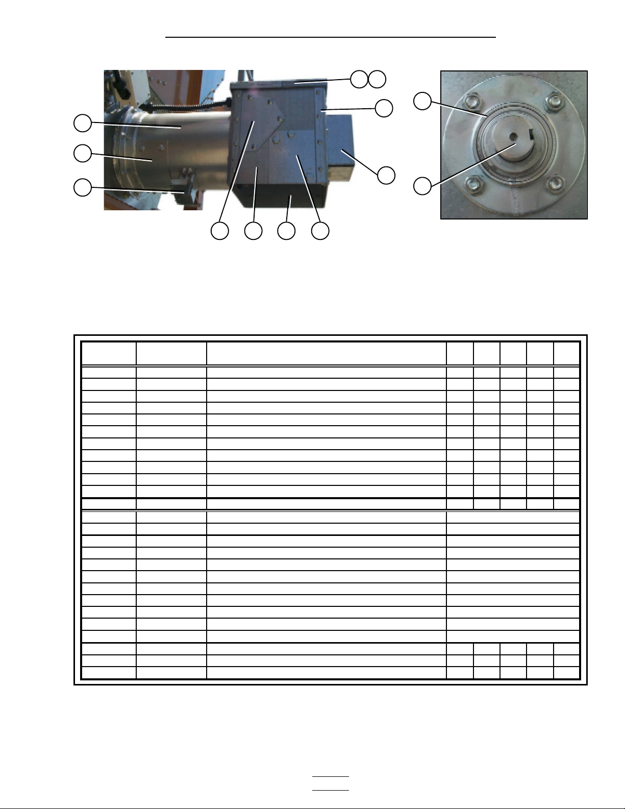
Metering Roll Drive
SCR Motor/Reduction drive and motor mount assembly.
1
7
2
34 5 6
8
9
14
9
14
10
Meter roll drive train components.
11
8
12 13
- 28 -
12
17
15
16
14
Page 29

2300 Series Parts Manual Bottom Module
Metering Roll Drive
Front meter roll bearing. Rear meter roll bearing.
18
19
20
ITEM
NUMBER
1 D01-0007 CORNER LEG PORTABLE DRYER 6 6688
2 D21-0010 FRAME RAIL, 14' LEFT 1
2 D31-0043 FRAME RAIL, 18' LEFT 1
2 D61-0001 FRAME RAIL, 20' LEFT 1
2 D101-0001 FRAME RAIL, 22' LEFT 1
2 D71-0002 FRAME RAIL, 26' LEFT 1
3 D01-0016 MOTOR MOUNT SUPPORT BRACKET 1 1111
4 D01-0081 MOTOR MOUNT 1 1111
5 D01-0704 SCR MOTOR GEARBOX MOUNT 1 1111
6 D01-0008 FRONT & REAR FRAME TIE CHANNEL 4 4466
7 D03-0232 MOTOR 3/4 HP DC W/GEAR BOX 50:1 1 1111
8 D01-1374 BOTTOM AUGER BEARING PLATE 1 1111
9 D02-0029 SPROCKET 40H30 2 2222
10 D31-0316 FRONT BOTTOM AUGER SHAFT 1 1111
11 D32-0001 FLANGETTE BEARING 1 1/2" 2 2222
12 D01-0196 SPROCKET IDLER ASSEMBLY 2 2222
13 D03-0257 SPROCKET 4015 x 7/8" BORE W/KEYWAY 1 1111
14 S-9168 KEY SQ. 1/4" x 1" 3 3333
15 S-6290 CHAIN #40 ROLLER CHAIN 6ft 6ft 6ft 6ft 6ft
16 D02-0031 #40 CHAIN CONNECTING LINK 1 1111
17 DC-972 DECAL, CHAIN WARNING 2 2222
18 D01-0003 ADAPTOR PLATE 4 4444
19 GK1583 FLANGETTE BEARING 1", W/LOCK COLLAR 4 4444
20 D01-0006 METER ROLL DRIVE SHAFT (front) 2 2222
21 D01-0272 METER ROLL SHAFT STUB (rear) 2 2222
PART
NUMBER
DESCRIPTION 2314 2318 2320 2322 2326
18
19
21
- 29 -
Page 30

2300 Series Parts Manual Top Module
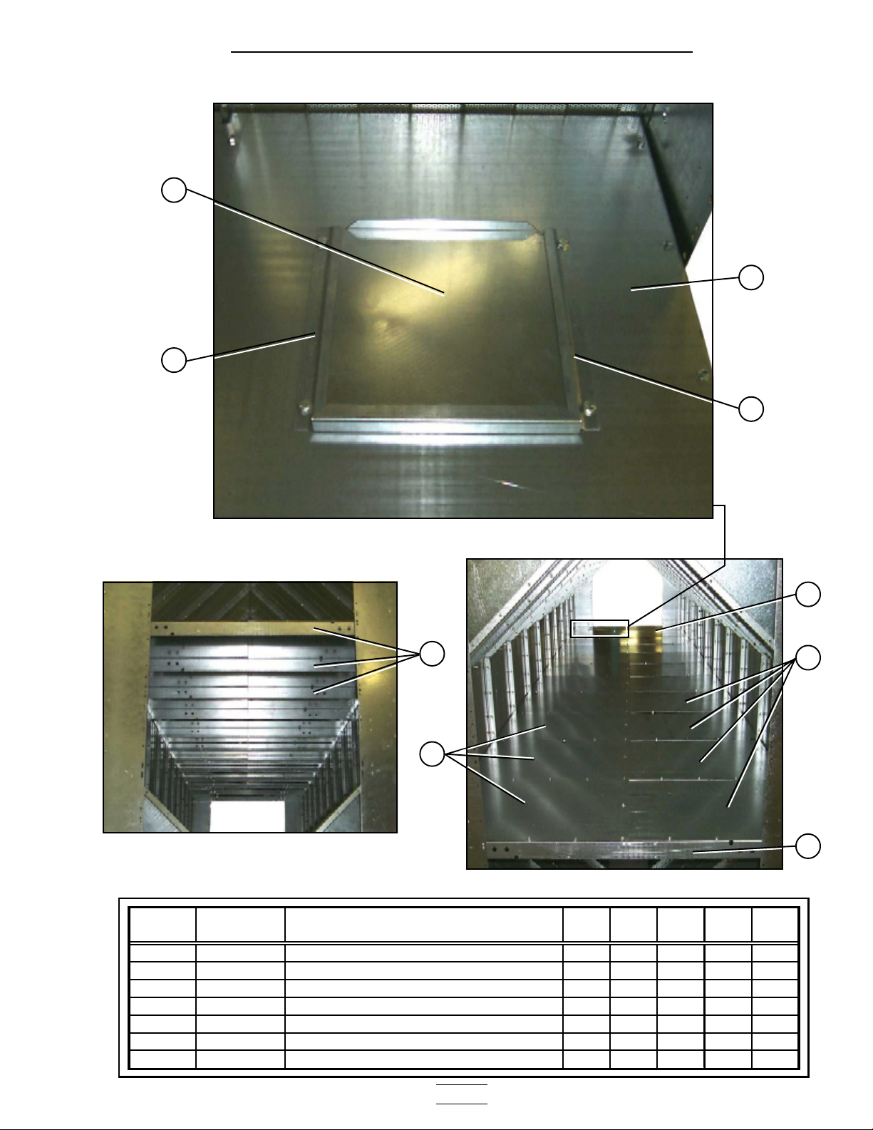
Frame / Lower Basket
Front view of the frame components.
6
6
7
66
4251
6
7
6 7
7
3
**NOTE: The parts pointed out on this page are listed on page 33.
- 30 -
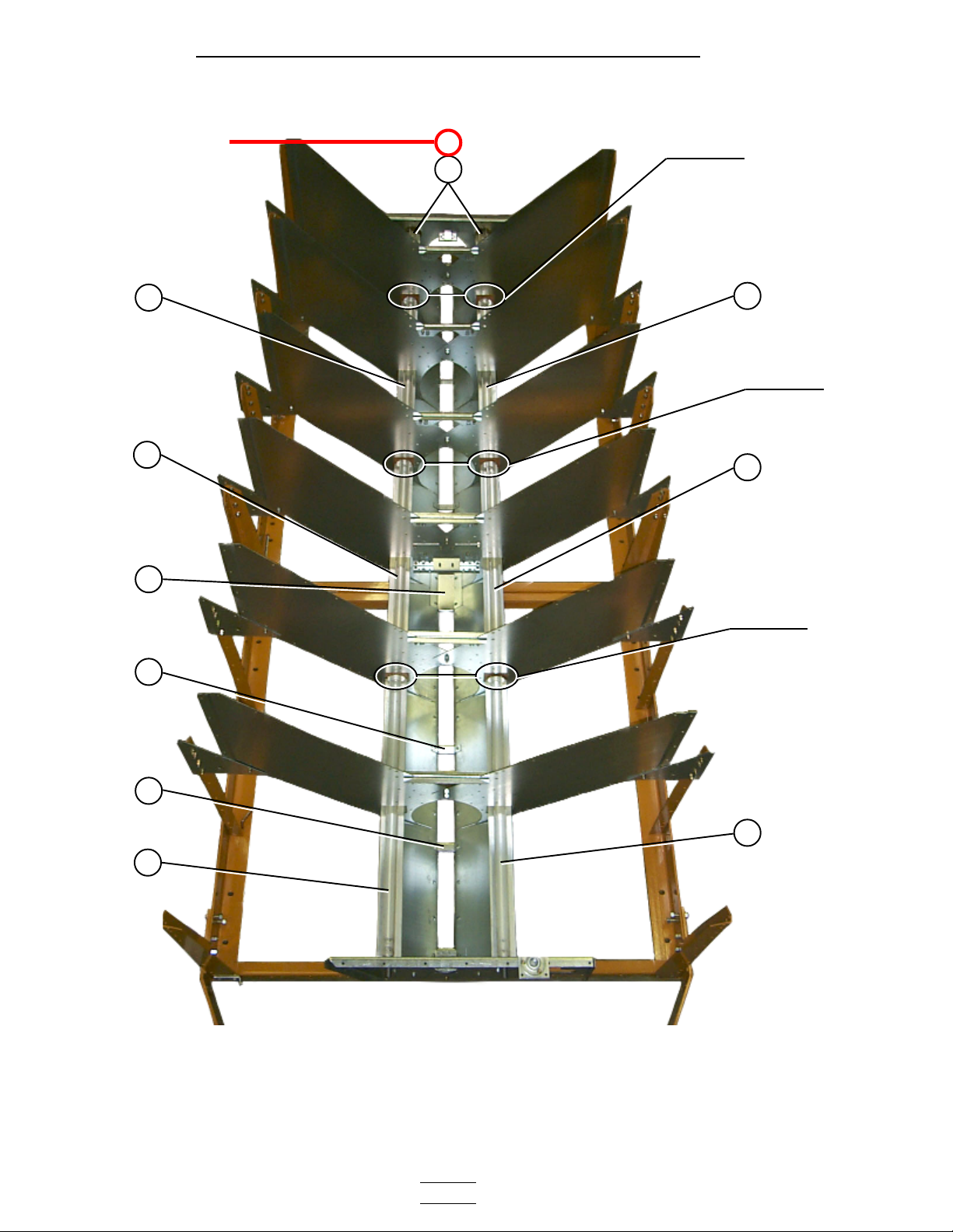
Page 31

2300 Series Parts Manual Top Module
Frame / Lower Basket
Front view of the frame and lower basket components.
8
9
6
7
6
7
4
6
2
5
9
10
8
6
1
**NOTE: The parts pointed out on this page are listed on page 33.
- 31 -
Page 32

10
2300 Series Parts Manual Top Module
Frame / Lower Basket
Rear view of the frame and lower basket components.
6
11
5
11
12
8
9
6
3
7
- 32 -
9
6
7
6
Page 33

2300 Series Parts Manual Top Module
Frame / Lower Basket
8
7
14
9
13
5
ITEM
NUMBER
1 D01-0012 HITCH BRACKET RIGHT 11111
2 D01-0011 HITCH BRACKET LEFT 11111
3 D21-0011 FRAME RAIL, 14' RIGHT 1
3 D31-0044 FRAME RAIL, 18' RIGHT 1
3 D61-0002 FRAME RAIL, 20' RIGHT 1
3 D101-0002 FRAME RAIL, 22' RIGHT 1
3 D71-0001 FRAME RAIL, 26' RIGHT 1
4 D21-0010 FRAME RAIL, 14' LEFT 1
4 D31-0043 FRAME RAIL, 18' LEFT 1
4 D61-0001 FRAME RAIL, 20' LEFT 1
4 D101-0001 FRAME RAIL, 22' LEFT 1
4 D71-0002 FRAME RAIL, 26' LEFT 1
5 D61-0048 FRAME TIE CHANNEL 22222
6 D01-0007 CORNER LEG PORTABLE DRYER 66688
7 D01-0005 SIDE LEG PORTABLE DRYER 10 14 16 16 20
8 D01-0004 GUSSET PLATE 16 20 22 24 28
9 D01-0101 GARNER BULKHEAD 24 32 36 40 48
10 D61-0077 CONNECTING SECTION END 22222
11 D61-0017 SCREEN,CONNECTING-INNER,GA,094 14 18 20 22 26
12 D61-0103P CONNECTING BULKHEAD EXTENSION 12 16 18 20 24
13 D61-0073 SCREEN,CONNECTING-OUTER,GA,094 14 18 20 22 24
14 D61-0019 MODULE TIE BRACE 6 8 10 10 12
PART
NUMBER
DESCRIPTION 2314 2318 2320 2322 2326
9
13
10
8
7
14
- 33 -
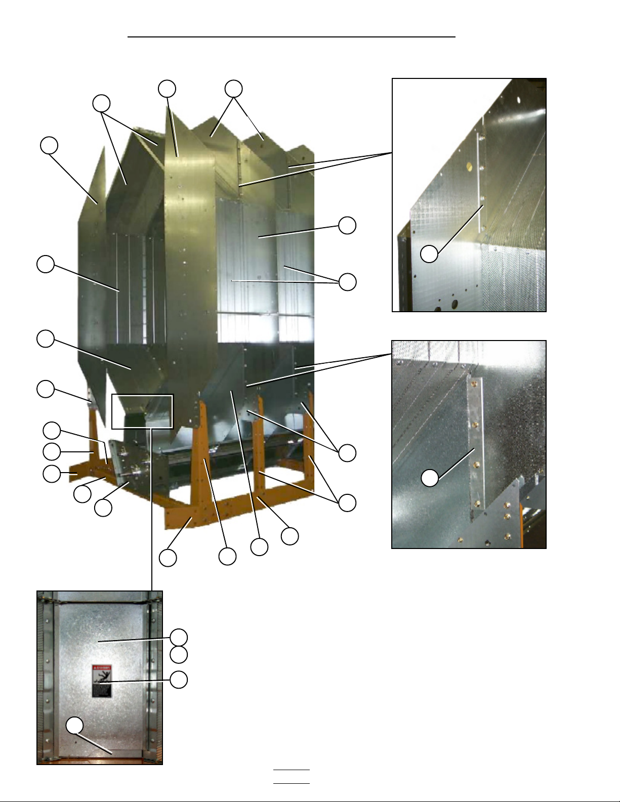
Page 34

*Note: Item 4 is
pointing to the top edge
angle gusset. There are
two types of gusset on
the dryer. The photo
right will help
distinguish the
difference between the
two. The arrows are
pointing to a tab on the
gusset that makes them
different (tabs are
“bent” up in photo).
Item 4a is used in two
places only; 1.) front
right of dryer 2.) rear
left of dryer, all others
are item 4.
2300 Series Parts Manual Top Module
Inside (Plenum) Screens / Outside Screens
1
4
4a
2
*
4
5
6
3
910
ITEM
NUMBER
PART
NUMBER
DESCRIPTION 2314 2318 2320 2322 2326
1 D01-0126 SCREEN,PLENUM TOP,GA,094 14 18 20 22 26
2 D31-0012 SCREEN,PLENUM WALL,GA,094 14 18 20 22 26
3 D01-0124 SCREEN,PLENUM BOTTOM,GA,094 14 18 20 22 26
4 D01-0152 LH TOP ANGLE GUSSET 12 16 18 20 24
4a D01-0153 RH TOP ANGLE GUSSET 2 2 2 2 2
5 D01-0127 SCREEN,ROOF,GA,094 14 18 20 22 26
6 D31-0013 SCREEN,OUTSIDE WALL,GA,094 14 18 20 22 26
7 D01-0128 SCREEN,HOPPER,GA,094 14 18 20 22 26
8 D61-0019 MODULE TIE BRACE 6 8 10 10 12
9 D61-0073 SCREEN,CONNECTING-OUTER,GA,094 14 18 20 22 24
10 D31-0307 COLUMN END PANEL 4 4 4 4 4
7
8
- 34 -
Page 35

2300 Series Parts Manual Top Module
Stiffener Attach Angles / Crane Brackets
1
1
2
3
See page 19 for the locations of the stiffener attach angle.
ITEM
NUMBER
1 D61-0015 TOP MODULE CRANE BRACKET 4 4 4 4 4
2 D61-0014 HOISTING SPREADER BAR 2 2 2 2 2
3 D01-0872 STIFFENER ATTACH ANGLE 6 8 10 10 12
PART
NUMBER
DESCRIPTION 2314 2318 2320 2322 2326
- 35 -
Page 36

2300 Series Parts Manual Top Module
Front End Panels / Fan Support / Grill Guard and Venturi
14
6
1
2
5a
5
Fan support extension attach angles.
1 2 3 4
Service platform attach bracket.
7
10 11 12 13
ITEM
NUMBER
1 D61-0023 TOP ANGLE, FAN SUPPORT PANEL 2 2 2 2 2
2 D61-0306 FAN SUPPORT EXTENSION, 42" FANS 1 1 1 1 1
3 D61-0307 TOP ANGLE (NOTCHED) FAN SUPPORT PANEL 1 1 1 1 1
4 D01-1829 STIFFENER, FAN SUPPORT EXT. 2 2 2 2 2
5 CD-0547 GRILL GUARD: 40&42" BLACK 1 1 1 1 1
5a CD-0545-Y VENTURI, 40" 1
5a CD-0546-Y VENTURI, 42" 1 1 1 1
6 D31-0307 COLUMN END PANEL 4 4 4 4 4
7 D01-1458 FRONT FAN SUPPORT, 1-40" 1
7 D51-0132 FRONT FAN SUPPORT, 1-42" 1 1 1 1
8 D01-0011 HITCH BRACKET, LH 1 1 1 1 1
8 D01-0012 HITCH BRACKET, RH 1 1 1 1 1
9 D61-0054 PLATFORM ATTACH BRACKET 2 2 2 2 2
10 D01-0029 HITCH WELDMENT 1 1 1 1 1
11 D51-0022 SUPPORT, CONTROL PANEL 6 6 6 6 6
12 D01-0062 FRONT DIAGONAL SUPPORT CHANNEL 2 2 2 2 2
13 D51-0021 STIFFENER, FRONT FAN SUPPORT 2 2 2 2 2
14 D01-1459 FRONT END PANEL 1-40" 1
14 D51-0131 FRONT END PANEL 1-42" 1 1 1 1
PART
NUMBER
DESCRIPTION 2314 2318 2320 2322 2326
8 9 10
- 36 -
Page 37

Rear End Panels / Rear Access Door / Front and Rear Ladders
Rear access door (outside).
7
8
9
2300 Series Parts Manual Top Module
10
2 2
4
1
10
11
3
Rear access door (inside).
12
13
8
12
13
7
14
5
6
15
NOTE: The Ladder assembly shown
above is the same for the front and rear on
upper modules.
ITEM
NUMBER PART NUMBER
1 D01-1780-Y REAR END PANEL 11111
2 D31-0307 COLUMN END PANEL 44444
3 D61-0097 LADDER MOUNTING BRACKET, REAR 33333
4-6 D01-1220 LADDER ASSY. STACK DRYER FRONT 11111
4 D61-0096 LADDER RUNG
5 D61-0094 LADDER SIDE RAIL-LH
6 D61-0095 LADDER SIDE RAIL-RH
7-15 RDA-29-Y REAR DOOR ASSEMBLY 29"SQ OCHR 11111
7 D01-1783-Y ASSIST HANDLE 29" SQ. DOOR
8 D01-1781-Y DOOR 29" SQUARE OCHRE
9 D03-0512 DOOR HANDLE,LOCKING CCW
10 D01-1782-BLK FRAME ANGLE 29" DOOR
11 DC-973 DECAL, DANGER FIRE HAZARD
12 401-4630-0 HINGE BRACKET-SQUARE DOOR
13 401-4669-8 HINGE-REAR ACCESS SQ DOOR
14 D01-0397 LATCH BRACKET
15 D01-1792 LATCH BAR 29" SQUARE DOOR
DESCRIPTION 2314 2318 2320 2322 2326
12/ASSEMBLY
1/ASSEMBLY
1/ASSEMBLY
2/ASSEMBLY
1/ASSEMBLY
1/ASSEMBLY
4/ASSEMBLY
2/ASSEMBLY
2/ASSEMBLY
2/ASSEMBLY
1/ASSEMBLY
1/ASSEMBLY
- 37 -
Page 38

2300 Series Parts Manual Top Module
Top Auger With Wet Bin Assembly
Top Auger with wet bin (switch paddle end).
6
5
2
1
1
43
7
9
13 14
14a
8
1
3
10
11
12
8
5
9
Top Auger (fill end).
- 38 -
Page 39

2300 Series Parts Manual Top Module
Top Auger With Wet Bin Assembly
Top Auger bearing support. Top Auger bearing support (inside view).
15
16
17
16
10 21 22 18
ITEM
NUMBER PART NUMBER
1 D01-1521 WET BIN SIDE,4'SIDE GALV. PERF 4 4 2 4
1 D01-1522 WET BIN SIDE,6'SIDE GALV. PER 2 6466
2 D01-0103 MERCURY SWITCH SHAFT 1 1111
3 D21-0003 TOP EDGE ANGLE 71.875" 2 2
3 D31-0004 TOP EDGE ANGLE 95.875" 2 2 4 4
3 D01-0168 TOP EDGE ANGLE 119.875" 2 4 2
3a D31-0003 TOP EDGE ANGLE SPLICE 2 2244
5 D01-0147 TOP AUGER HOUSING HINGE L.H. 2 2222
6 D01-0167 MERCURY SWITCH PADDLE WELDMENT 1 1111
7 D21-0015 AUGER TOP FRONT WELDMENT 1 1
7 D31-0091 AUGER TOP FRONT WELDMENT 1 1 1
7 D31-0267 AUGER TOP & BOTTOM WELDMENT 1 1 2 2
7 D61-0184 AUGER WELDMENT 117 7/8" 1
8 D01-0148 TOP AUGER HOUSING HINGE R.H. 2 2222
9 D01-1525 WET BIN END 2 2222
10 D21-0002 TOP AUGER TROUGH SIDE/6' 2 2
10 D31-0010 TOP AUGER TROUGH SIDE/8' 2 2 4 4
10 D01-0161 TOP AUGER TROUGH SIDE/10' 2 4 2
11 D01-1650 REAR AUGER BEARING COVER 1 1111
12 D31-0028 TOP AUGER HOUSING END 2 2222
13 D32-0001 BEARING 1 1/2" DIA W/FLANGETTE 2 2222
14 D31-0090 SHAFT, TOP AUGER FRONT 1 1111
14a D31-0005 SHAFT, TOP AUGER STUB REAR 1 1111
15 D01-1123 TOP AUGER COVER, 30.25" 1 1111
15 D01-1124 TOP AUGER COVER, 24.25" 3 5757
15 D01-1125 TOP AUGER COVER, 20.25" 2 2244
16 D31-0015 TOP AUGER BEARING SUPPORT 1 1122
17 D31-0011 CENTER STABILIZER BEAM 1 1122
18 D31-0009 GUSSET ATTACH BRACKET 2 2244
19 D31-0001 CENTER HANDRAIL GUSSET L.H. 2 2244
20 D31-0002 CENTER HANDRAIL GUSSET R.H. 2 2244
21 D21-0001-Y HAND RAIL-SUPPORT,1"EMTX71.75" 2 2
21 D31-0006-Y HAND RAIL SUPPORT,1"EMTX95.75" 2 2 4 4
21 D01-0151-Y HAND RAIL, 1"EMT X119.75"LONG 2 4 2
22 D01-0140 HANGER BRACKET-HANDRAIL GALV. 16 16 16 24 24
23 D31-0008 TOP AUGER TROUGH SPLICE 2 2244
24 D01-1245 TOP AUGER BEARING HANGER ASSY. 1 1122
25 D31-0076 SHAFT, AUGER SPLICE 1 1122
21
22
20
7
23
24
7
25
19
DESCRIPTION 2314 2318 2320 2322 2326
- 39 -
Page 40

2300 Series Parts Manual Top Module
Top Auger Drive
1
6
1
2
3
4
Belt guard upper mount.
5
Top Auger drive components.
Top Auger belt guard cover.
12
13
- 40 -
Page 41

2300 Series Parts Manual Top Module
Top Auger Drive
7
8
9
10
11
Top Auger motor and motor mount.
ITEM
NUMBER PART NUMBER
1 D01-0453 TOP AUGER BELTGARD BODY 11111
2 D52-0001 SHEAVE 2GR 16" GRIPBELT 11111
3 D32-0019 BUSHING Q1-1 1/2" SPLIT TAPER 11111
4 D01-0464 BELT-V BX97 22222
5 2818-2 SHEAVE 2GR 3.35Dx1 1/8" BORE 1 1
5 D62-0003 SHEAVE 2GR 4.25Dx1 3/8" 1 1 1
6 D01-0155 MOUNTING BRACKET-BELT GD SPCR 11111
7 D01-0424 DRYER TOP HAND HOLD 11111
* 8 500-1 MOTOR 5HP 1PH 1800RPM 1
8 500-3 MOTOR 5HP 3PH 1800RPM 1 1
8 712-3 MOTOR 7.5HP 3PH 1800RPM 1 1
8 1000-3 MOTOR 10HP 3PH 1800RPM 1
9 D01-0173 TOP MOTOR MOUNT WELDMENT 11111
10 D01-0465 TURNBUCKLE 1/2" X 6" PLATED 11111
11 D01-0170 ANCHOR BRACKET-MOTOR MOUNT 11111
12 D01-0452-Y TOP AUGER BELTGUARD COVER OCHR 11111
13 DC-971 DECAL, BELT DRIVE WARNING 22222
DESCRIPTION 2314 2318 2320 2322 2326
*ITEM 8, PART No. 500-1 IS A SINGLE PHASE MOTOR
- 41 -
Page 42

2300 Series Parts Manual Fan Heaters
Fan Heater Housing Assembly
Fan Heater housing assembly. 26” & 28” burner support and
collector cup.
1
2
3
14a
13a
13
14
36”-42” burner support and collector cup.
4 412
5 7 8 9 10 11
4 5 4
6 6
Heater access panel assembly (left photo is outside and right photo is inside of the door). Items 4 through
8 make up the heater access panel assembly (part no. CD-APA6065).
- 42 -
Page 43

2300 Series Parts Manual Fan Heaters
Fan Heater Housing Assembly
ITEM
NUMBER
1 D01-0535 WRAPPER, 28" FAN HEATER 1
1 D01-1470 WRAPPER, 36" FAN HEATER 1
1 D01-1471 WRAPPER, 40" FAN HEATER 1
1 D01-1472 WRAPPER, 42" FAN HEATER 1
2 D01-0529 STRAIGHTENING VANE, 28" F/H 11
2 D01-1452 STRAIGHTENING VANE, 36-42" F/H 11 11 11
3 D01-0528 INNER CAN, 28" F/H 1
3 D01-1480 INNER CAN, 36" F/H 1
3 D01-1479 INNER CAN, 40" F/H 1
3 D01-1451 INNER CAN, 42" F/H 1
4-8 CD-APA6065 HEATER ACCESS PANEL ASSEMBLY 1 1 1 1
4 TFH-2046 SPRING LATCH W/BLK KNOB
5 HF-6062 HEATER ACCESS PANEL
6 HF-6063 ACCESS PANEL LATCH
7 HF-7379 HEATER COVER PLATE
8 HF-7380 WINDOW ACCESS .060x6x6 PLASTIC
9 DC-1224 DECAL, DANGER HI-VOLTAGE 1 1 1 1
10 DC-1227 DECAL, WARNING FIRE 1 1 1 1
11 DC-1225 DECAL, WARNING ROTATING BLADE 1 1 1 1
12 DC-113 DECAL, AIR FLOW 1 1 1 1
13 HF-983 COLLECTOR CUP, 28" FAN HEATER 1
13a D01-1484 COLLECTOR CUP, 36" FAN HEATER 1
13a D01-1485 COLLECTOR CUP, 40" FAN HEATER 1
13a TF-1217 COLLECTOR CUP, 42" FAN HEATER 1
14 HF-7092 SUPPORT PLATE, 28" FAN HEATER 1
14a D01-1482 SUPPORT BRACKET, 36" FAN HEATER 1
14a D01-1483 SUPPORT BRACKET, 40" FAN HEATER 1
14a TF-1216 SUPPORT BRACKET, 42" FAN HEATER 1
PART
NUMBER
DESCRIPTION 28" 36" 40" 42"
2/ASSEMBLY
1/ASSEMBLY
2/ASSEMBLY
1/ASSEMBLY
1/ASSEMBLY
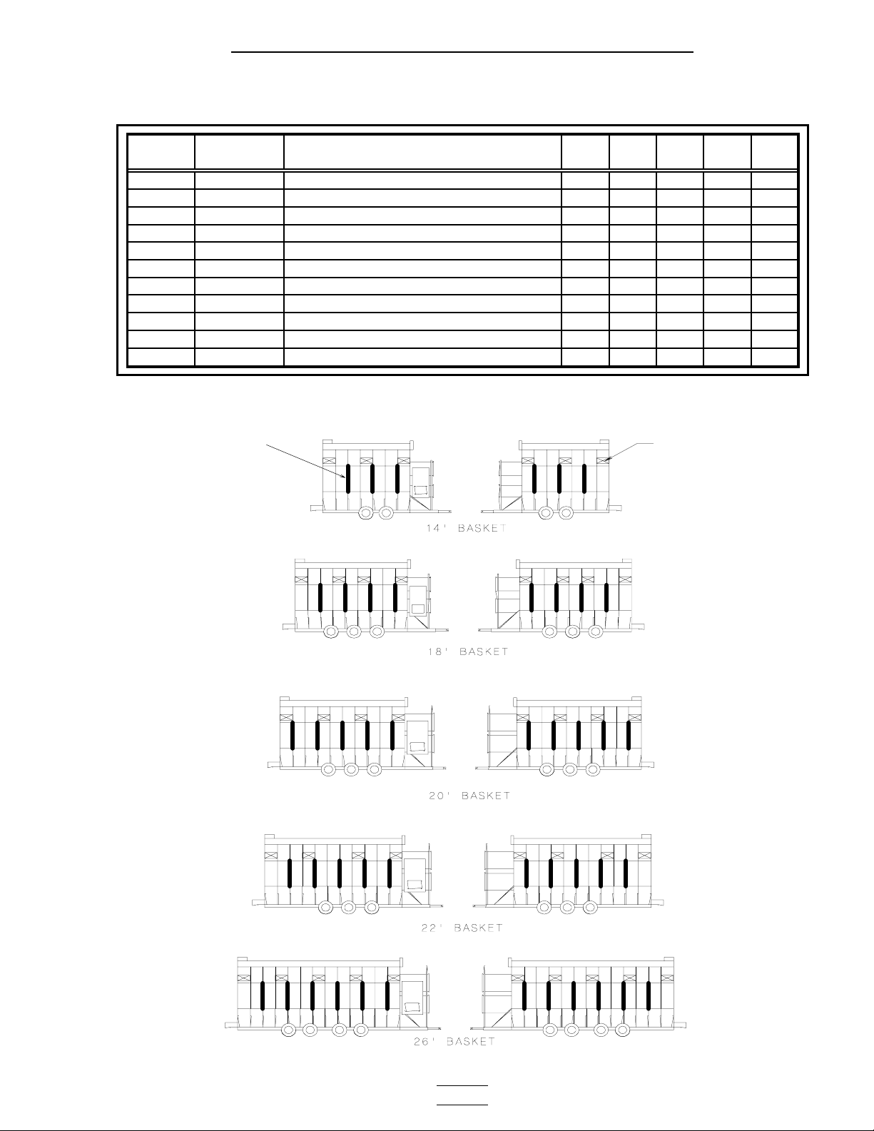
Matching the right size fan heater to the model number of the dryer.
TOP MODULE
Fan 3
Dryer Model No.
Fan Heater
40", 10 - 16 hp (4015) x
42", 20 hp (4220) x
42", 25 hp (4225) x
42", 30 hp (4230) x
42", 40 hp (4240) x
BOTTOM MODULE
2314 2318 2320 2322 2326
Fan 1&2
Dryer Model No.
Fan Heater
28", 10 - 12 hp (2812) x
36", 10 - 12 hp (3612) x
36", 10 - 16 hp (3615) x x
40", 25 hp (4025) x
- 43 -
2314 2318 2320 2322 2326
Page 44

2300 Series Parts Manual Fan Heaters
(
)
Fan Motor / Motor Mount / Fan Blade
Fan motor and motor mount. Fan blade and bushing.
1 2 3 4
FAN HEATER;
Dia., HP
28" 12Hp
36" 12Hp
36" 15Hp
40" 15Hp
40" 25Hp
42" 20Hp
42" 25Hp
42" 30Hp
42" 40Hp
ITEM NUBER
1 MOTOR MOUNT D01-0530 D01-0530 D01-0530 D01-0530 D01-0530
2 MOTOR CD-0110 CD-0239 CD-0239 CD-0239 D03-0193
3 FAN BLADE D03-0302 D03-0302 D03-0302 D03-0302 D03-0302
4 BUSHING PT0778 PT0778 PT0778 PT0778 PT0778
1 MOTOR MOUNT D01-1478 D01-1478 D01-1478 D01-1478 D01-1478
NOT SHOWN MOTOR MOUNT ADAPTER CD-0233 CD-0233 CD-0233 CD-0233 CD-0233
2 MOTOR CD-0110 CD-0239 CD-0239 CD-0239 CH-6819
3 FAN BLADE D01-0468 D01-0468 D01-0468 D01-0468 D01-0468
4 BUSHING FH-1009 FH-1009 FH-1009 FH-1009 FH-1009
1 MOTOR MOUNT D01-1478 D01-1478 D01-1478 D01-1478 D01-1478
2 MOTOR 002-1073-2 CH-1050 CH-1050 CH-1050 CH-6820
3 FAN BLADE D82-0002 D82-0002 D82-0002 D82-0002 D82-0002
4 BUSHING FH-1009 FH-6963 FH-6963 FH-6963 FH-6963
1 MOTOR MOUNT D01-1481 D01-1481 D01-1481 D01-1481 D01-1481
2 MOTOR CD-0571 CH-1050 CH-1050 CH-1050 CH-6820
3 FAN BLADE D03-0567 D03-0567 D03-0567 D03-0567 D03-0567
4 BUSHING GC03810 GC03810 GC03810 GC03810 GC03810
1 MOTOR MOUNT N/A D01-1477 D01-1477 D01-1477 D01-1477
2 MOTOR N/A C-2049 C-2049 C-2049 CH-6692
3 FAN BLADE N/A D72-0003 D72-0003 D72-0003 D72-0003
4 BUSHING N/A CE-00617 CE-00617 CE-00617 CE-00617
1 MOTOR MOUNT N/A D01-1453 D01-1453 D01-1453 D01-1453
2 MOTOR N/A CH-1051 CH-1051 CH-1051 2000-3-5
3 FAN BLADE N/A D01-0470 D01-0470 D01-0470 D01-0470
4 BUSHING N/A GC03810 GC03810 GC03810 GC03810
1 MOTOR MOUNT N/A D01-1474 D01-1474 D01-1474 D01-1474
2 MOTOR N/A C-2049 C-2049 C-2049 CH-6692
3 FAN BLADE N/A D01-0471 D01-0471 D01-0471 D01-0471
4 BUSHING N/A CE-00617 CE-00617 CE-00617 CE-00617
1 MOTOR MOUNT N/A D01-1474 D01-1474 D01-1474 D01-1474
2 MOTOR N/A TFH-2011 TFH-2011 TFH-2011 CH-6917
3 FAN BLADE N/A D01-0471 D01-0471 D01-0471 D01-0471
4 BUSHING N/A CE-00617 CE-00617 CE-00617 CE-00617
1 MOTOR MOUNT N/A D01-1474 D01-1474 D01-1474 D01-1474
2 MOTOR N/A CH-6848 CH-6848 CH-6848 CH-6887
3 FAN BLADE N/A D01-0471 D01-0471 D01-0471 D01-0471
4 BUSHING N/A CE-00617 CE-00617 CE-00617 CE-00617
DESCRIPTION
220V 1Ph 208V 3Ph 220V 3Ph 440V 3Ph 575V Ph
PART NUMBER
- 44 -
Page 45

2300 Series Parts Manual Fan Heaters
Air Mixer Assemblies
Air mixer assemblies (36” air mixer shown in photo).
1
1a
2
ITEM
NUMBER
1-2 D01-0955 AIR MIXER ASSEMBLY, 28" 1
1 D01-0951 AIRMIXER CAN, 28" x 15" LONG
1a D01-0950 AIRMIXER CAN, 28" x 8" SHORT
2 CD-0228 SMALL DIA. CAN AIR MIXER VANE
1-2 CD-0113 AIR MIXER ASSEMBLY, 36" 1
1&1a D01-1303 AIRMIXER CAN, 36" W/ACCESS
2 CD-0083 AIR MIXER VANE
1-2 CD-0117 AIR MIXER ASSEMBLY, 40" 1
1&1a D01-1218 AIRMIXER CAN, 40" W/ACCESS
2 CD-0083 AIR MIXER VANE
1-2 CD-0118 AIR MIXER ASSEMBLY, 42" 1
1&1a CD-0192 AIRMIXER CAN, 42"
2 CD-0083 AIR MIXER VANE
PART
NUMBER
DESCRIPTION
28"
F/H
36"
F/H
1/ASSEMBLY
1/ASSEMBLY
6/ASSEMBLY
2/ASSEMBLY
8/ASSEMBLY
2/ASSEMBLY
8/ASSEMBLY
2/ASSEMBLY
8/ASSEMBLY
40"
F/H
42"
F/H
- 45 -
Page 46

2300 Series Parts Manual Fan Heaters
Flame Probe / Ignitor / Burner Assemblies
Ignitor and flame probe assemblies.
Flame probe Ignitor
8
1
2
3
4
7
6
5
28” Fan heater burner assembly.
9
12
10 11
- 46 -
Page 47

2300 Series Parts Manual Fan Heaters
Flame Probe / Ignitor / Burner Assemblies
36” & 40” Fan heater burner assembly.
13
14
16
42” Fan heater burner assembly.
1715
2018 2119
ITEM
NUMBER PART NUMBER
1-3 TF-1559-N FLAME PROBE ASSY NETWK 1111
1 HH-7025 BOOT 8MM SILICONE 90DEGREE
2 THH-4179 FLAME SENSOR 6" LONG ROD
3 CD-0187 FLAME SENSOR BRACKET
4-8 TF-1558 IGNITOR ASSEMBLY 1111
4 HF-7204 DUAL PROBE IGNITOR BRACKET
5 D01-0878 IGNITOR AIR DEFLECTOR ANGLE
6 HF-7201 IGNITOR HALF CLAMP
7 CD-0238 IGNITOR FLAME
8 TF-1876 IGNITION WIRE ASSY (includes both wires)
9-12 BA-28 28" BURNER ASSEMBLY 1
9 HF-7629 DIVERTER WELDMENT 28"
10 THF-3144 FLAME SPREADER 28"
11 THF-3141 HEATER GUN MACHINED 28"
12 THF-3113 28" DIVERTER BRACKET
13-17 BA-36 36" BURNER ASSEMBLY 1
13 THF-3038 DIVERTER BRACKET 36" & 40"
14 THF-3038P DIVERTER BRACKET 36" & 40" PERFED
15 THF-3057 FLAME SPREADER 36-42"
16 THF-3039 DIVERTER BRACKET 36" & 40" W/HOLE
17 CD-0091 BURNER WELDMENT CD 36" & 40"
13-17 BA-40 40" BURNER ASSEMBLY 1
13 THF-3038 DIVERTER BRACKET 36" & 40"
14 THF-3038P DIVERTER BRACKET 36" & 40" PERFED
15 THF-3057 FLAME SPREADER 36-42"
16 THF-3039 DIVERTER BRACKET 36" & 40" W/HOLE
17 CD-0091 BURNER WELDMENT CD 36" & 40"
18-21 BA-42 42" BURNER ASSEMBLY 1
18 CD-0448P DIVERTER BRACKET 42" PERFD
19 CD-0448 DIVERTER BRACKET 42"
20 CD-0208 BURNER WELDMENT CD 42"
21 THF-3057 FLAME SPREADER 36-42"
DESCRIPTION
28"
F/H
36"
F/H
1/ASSEMBLY
1/ASSEMBLY
1/ASSEMBLY
1/ASSEMBLY
1/ASSEMBLY
2/ASSEMBLY
2/ASSEMBLY
1/ASSEMBLY
1/ASSEMBLY
1/ASSEMBLY
1/ASSEMBLY
1/ASSEMBLY
3/ASSEMBLY
4/ASSEMBLY
1/ASSEMBLY
1/ASSEMBLY
1/ASSEMBLY
3/ASSEMBLY
4/ASSEMBLY
1/ASSEMBLY
1/ASSEMBLY
1/ASSEMBLY
4/ASSEMBLY
4/ASSEMBLY
1/ASSEMBLY
1/ASSEMBLY
40"
F/H
42"
F/H
- 47 -
Page 48

2300 Series Parts Manual Fan Heaters
LP Pipe Train Assemblies
28” Fan Heater LP pipe train assembly.
E
10
9 8
B
7
F
1
2
3 4 5 6
A
A
CD
21 18 16
C
B
11
12
13
14
14
13
28
15 16 19 17 15 15 20 21
D
27 22 26 22
22 23 24 25 3
10 29 30 29
20a
E
- 48 -
Page 49

2300 Series Parts Manual Fan Heaters
LP Pipe Train Assemblies
F
32 7
34
6
31
31
7
ITEM
NUMBER
1 A D67-0005
2 A HH-7013
3 A,C HH-3854
4 A THH-4058
5 A D07-0019
6 A,F HH-4847
7 A,F TFC-0095
8 B TFC-0081
9 B HH-2984
10 B,E D03-0241
11 B D18-0002
12 B HH-1254
13 B,D HH-1255
14 B,D 033-1016-6
15 B THH-4121
16 B,C S-7259
17 B CD-0179
18 C CD-0044
19 B THH-4154
20 B THH-4149
21 B,C HH-6502
22 C,D THH-4128
23 C HH-1453
24 C HH-2029
25 C TFC-0023-50
26 D TFC-0030
27 D TFC-0032
28 D HH-1932
29 E THH-4120
30 E D08-0020 NIPPLE 3/4" x 6" SCH 40 1
31 F HH-1082 ELBOW 1/2" - 90 STREET SCH 80 2
32 F HF-7056 VAPORIZER PIVOT BRKT 2
33 F HF-7060 VAPORIZER SUPPORT WELDMENT 1
34 F HF-7057 VAPORIZER ADJUSTMENT BRKT 1
NOT
SHOWN
PHOTO
(A,B,C,D,E) PART NUMBER
COUPLER 1/2" SCH 40
SWITCH SCREW-IN VAPOR HI-LIMIT
NIPPLE 1/2" x 6" SCH 80
TEE 1/2" x 1/2" x 1/2" SCH 80
NIPPLE 1/2" x 1 1/2" SCH 80
ELBOW 1/2" - 90 SCH 80
HOSE, 1/2" x 24", LP GAS ASSY
VALVE, 3/4" NPT SOLENOID
GUAGE, 0-30# PRESSURE LP
NIPPLE 3/4" x 8" SCH 40
TEE 3/4 x 1/2 x 3/4 SCH 40
CONNECTOR UI-8D MALE FLARE
NUT 1/2" BRASS FORGED FLARE
COPPER TUBE 3/8ID WITH 1/2OD
NIPPLE 3/4" CLOSE SCH 40
U-BOLT 5/16-18x1 1/2 ZN
PIPETRAIN SADDLE BRACKET
PIPETRAIN SUPPORT BRACKET
TEE 3/4" x 3/4" x 1/4" SCH 40
ELBOW 3/4" - 1/2" REDUCER SCH 40
NIPPLE 1/2" x 7" SCH 40
NIPPLE 1/2" x 2" SCH 40
TEE 1/2" x 1/2" x 1/2" SCH 40
NIPPLE 1/2" x 1 1/2" SCH 40
REGULATOR 1/2" NPT 50P.S.I.
VALVE 1/2" NPT BALL
VALVE 1/2" NPT SOLENOID
ELBOW 1/2" PIPE - 1/2" FLARE BRASS
ELBOW 3/4" - 90 SCH 40
N/A CD-0414 VAPORIZOR COIL 26 28" 3 WRAP 1
DESCRIPTION 28"
33
32
1
1
1
1
1
3
2
1
1
1
1
1
2
1 ft
3
3
1
1
1
1
1
2
1
1
1
1
1
1
2
- 49 -
Page 50

2300 Series Parts Manual Fan Heaters
LP Pipe Train Assemblies
36” Fan Heater LP pipe train assembly.
C
B
D
E
A
B
10
11
12
1
3
5
7642
8
9
A
13
14
15
16 11 17 11
24
18
10
25
18 19 20 19
C
D
19
21
14
4 3 22 23 4 4
- 50 -
1
Page 51

2300 Series Parts Manual Fan Heaters
LP Pipe Train Assemblies
E
29
26
27
32
33
28 8 27
ITEM
NUMBER
1 A,D D07-0029
2 A,D CD-0044
3 A,D S-7259
4 A,D THH-4121
5 A,D D67-0021
6 A,D HH-7013
7 A,D D67-0005
8 A,E HH-3854
9 A HF-7225
10 A,D D18-0002
11 A,B THH-4128
12 A TFC-0020
13 B 033-1016-6
14 B,D HH-1255
15 B HH-1932
16 B TFC-0032
17 B TFC-0030
18 C,D D03-0241
19 C,D THH-4120
20 C,D D08-0018
21 D HH-1254
22 D THH-4154
23 D CD-0179
24 D HH-2984
25 D TFC-0081
26 E TFC-0095
27 E HH-4847
28 E HF-7081
29 HF-7057 VAPORIZER ADJUSTMENT BRACKET 1
30 HF-7056 VAPORIZER PIVOT BRACKET 2
31 HF-7060 VAPORIZER SUPPORT WELDMENT 1
32 HH-7016 GROMMET, 1 1/2" I.D. 2
33 HF-7207 VAPORIZER COIL 1
PHOTO
(A,B,C,D,E) PART NUMBER
DESCRIPTION 36"
NIPPLE 3/4"x 11" SCH 40
PIPETRAIN SUPPORT BRACKET
U-BOLT 5/16-18x1 1/2 ZN
NIPPLE 3/4" CLOSE SCH 4O
NIPPLE 3/4 CLOSE SCH 80
SWITCH SCREW-IN VAPOR HI-LIMIT
COUPLER 1/2" SCH 40
NIPPLE 1/2x6 SCH 80
TEE 3/4x1/2x1/2
TEE 3/4 X 1/2 X 3/4
NIPPLE 1/2 x 2 SCH 40
REGULATOR 3/4"
COPPER TUBE 3/8ID WITH 1/2OD
NUT 1/2" BRASS FORGED FLARE
ELBOW 1/2"PIPE/1/2"FLARE BRASS
VALVE 1/2" NPT SOLENOID
VALVE 1/2" NPT BALL
NIPPLE 3/4X8" SCH.40
ELBOW 3/4"-90 SCH 40
NIPPLE 3/4 X 4" SCH 40
CONNECTOR UI-8D MALE FLARE
TEE 3/4"-3/4"-1/4" SCH 40
PIPETRAIN SADDLE BRACKET
GAUGE 0-30# PRESSURE LP
VALVE 3/4" NPT SOLONOID
HOSE, 1/2" x 24", LP GAS
ELBOW 1/2"-90 SCH 80
VAPORIZER MOUNTING PLATE 1/2"
30
31
30
1
1
3
4
1
1
1
1
1
2
2
1
1 ft
2
1
1
1
1
3
1
1
1
1
1
1
2
3
1
- 51 -
Page 52

2300 Series Parts Manual Fan Heaters
LP Pipe Train Assemblies
40” & 42” Fan Heater LP pipe train assembly.
C
B
D
E
A
B
10
11
12
1
3
5
7642
8
9
A
13
14
15
16 11 17 11
26
18
21
22
27
18 19 20 19
C
D
19a
23
14
4 3 24 25 4 4
- 52 -
1
Page 53

2300 Series Parts Manual Fan Heaters
LP Pipe Train Assemblies
31
28
29
34
35
30 8 29
E
ITEM
NUMBER
1 a,d D07-0029
2 a,d CD-0044
3 a,d S-7259
4 a,d THH-4121
5 a,d D67-0021
6 a,d HH-7013
7 a,d D67-0005
8 a,e HH-3854
9 a HF-7225
10 a D18-0002
11 a,b THH-4128
12 a TFC-0020
13 b 033-1016-6
14 b,d HH-1255
15 b HH-1932
16 b TFC-0032
17 b TFC-0030
18 c,d D01-1778
19 c,d THH-4115
19a d THH-4120
20 c,d THH-4151
21 d D08-0017
22 d THH-4005
23 d HH-1254
24 d THH-4154
25 d CD-0179
26 d HH-2984
27 d TFC-0081
28 e TFC-0095
29 e HH-4847
30 e HF-7081 VAPORIZER MOUNTING PLATE 1/2" 1 1
31 HF-7057 VAPORIZER ADJUSTMENT BRACKET 1 1
32 HF-7056 VAPORIZER PIVOT BRACKET 2 2
33 HF-7060 VAPORIZER SUPPORT WELDMENT 1 1
34 HH-7016 GROMMET, 1 1/2" I.D. 2 2
35 HF-7207 VAPORIZER COIL 1 1
PHOTO
(A,B,C,D,E) PART NUMBER
DESCRIPTION 40" 42"
NIPPLE 3/4"x 11" SCH 40
PIPETRAIN SUPPORT BRACKET
U-BOLT 5/16-18x1 1/2 ZN
NIPPLE 3/4" CLOSE SCH 4O
NIPPLE 3/4 CLOSE SCH 80
SWITCH SCREW-IN VAPOR HI-LIMIT
COUPLER 1/2" SCH 40
NIPPLE 1/2x6 SCH 80
TEE 3/4x1/2x1/2
TEE 1x1x3/4 SCH 40
NIPPLE 1/2 x 2 SCH 40
REGULATOR 3/4"
COPPER TUBE 3/8ID WITH 1/2OD
NUT 1/2" BRASS FORGED FLARE
ELBOW 1/2"PIPE/1/2"FLARE BRASS
VALVE 1/2" NPT SOLENOID
VALVE 1/2" NPT BALL, BRONZE
NIPPLE 1" X 10 1/4" SCH 40
ELBOW 1"-90 DEG SCHED 40
ELBOW 3/4"-90 SCH 40
NIPPLE 1" X 3" SCH 40
TEE 1X1X3/4" SCH40
RDCR 1"X1/2" HEX BUSHING SCH40
CONNECTOR UI-8D MALE FLARE
TEE 3/4"-3/4"-1/4" SCH 40
PIPETRAIN SADDLE BRACKET
GAUGE 0-30# PRESSURE LP
VALVE 3/4" NPT SOLONOID
HOSE, 1/2" x 24", LP GAS
ELBOW 1/2"-90 SCH 80
11
11
33
44
11
11
11
11
11
11
22
11
1 ft 1 ft
22
11
11
11
11
22
11
11
11
11
11
11
11
11
11
22
33
32
33
32
- 53 -
Page 54

2300 Series Parts Manual Fan Heaters
NG Pipe Train Assemblies
36”, 40”, & 42” Natural gas pipe train assembly.
C
B
1
54
A
D
6 3 7 8 9 7 10 7
C
3
B C
1
12 15
14
12
1a
5
4
1
11 12 13 14
7616
- 54 -
Page 55

2300 Series Parts Manual Fan Heaters
"
NG Pipe Train Assemblies
11
19
5
17
12
4
18 12
D
ITEM
NUMBER
1 A,B,C D08-0011 ELBOW 1 1/2"-90 SCH 40 4 4
1a A,B,C GT3-0553 RDCR, HEX 1 1/2" x 3/4" (FOR ORIFICE) 1
1a A,B,C D08-0007 RDCR 1 1/2" x 1" (FOR ORIFICE) 1
2 A,B,C D08-0013 NIPPLE 1 1/2 X 3" SCH40 1 1
3 A,B,C D08-0001 NIPPLE 1 1/2"x6" SCH 40 1 1
4 A,C,D S-6643 CONDUIT HANGER 1 1/2 3 3
5 A,C,D TF-1239 ANGLED PIPETRAIN BRKT, 36-42" 3 3
6 B,C D03-0445 TEE 1 1/2"x1"x1 1/2" SCH40 2 2
7 B,C D08-0009 NIPPLE 1 1/2" CLOSE SCH 40 4 4
8 B,C D08-0022 GAUGE PRESSURE 0-15# PSI 1 1
9 B,C THH-4001 RDCR 1"x1/4"HEX BUSHING S40 1 1
10 B,C TF-1536 VALVE 1-1/2" NPT SOLONOID 1 1
11 B,D HH-7038 ELBOW 1"-45 SCH 40 1 1
12 B,C,D THH-4117 NIPPLE 1" CLOSE SCH 40 3 3
13 B D38-0001 TEE 1 1/2"x1 1/2"x1" SCH40 1 1
14 B,C D03-0446 NIPPLE 1.5"X11.5" SCH40 1 1
15 C TFC-0093 VALVE 1" NPT BRONZE BALL 1 1
16 C THH-4151 NIPPLE 1" X 3" SCH 40 1 1
17 D THH-4115 ELBOW 1"-90 DEG SCHED 40 1 1
18 D TFC-0031 VALVE 1" NPT SOLENOID 1 1
19 D D68-0020 HOSE 1
PHOTO
(A,B,C,D)
PART
NUMBER
DESCRIPTION 36" F/H
X 9" GAS 1 1
40" &
42" F/H
- 55 -
Page 56

2300 Series Parts Manual Fan Heaters
28” Natural gas pipe train assembly.
NG Pipe Train Assemblies
431 2
18
6
5
6
3
7
3
1
2
6
8
9 1 2
3
4
15
10
17
9
16
16
6
15
11
12
13
6
14
- 56 -
Page 57

2300 Series Parts Manual Fan Heaters
" #
Fan Heater Orifices
28" FAN HEATER NATURAL GAS PIPE TRAIN
ITEM
NUMBER
1 TF-1239 ANGLED PIPE TRAIN BRACKET 3
2 D62-0005 CLAMP 3/4" 3
3 D08-0018 NIPPLE, 3/4 x 4" SCH 40 4
4 THH-4120 ELBOW, 3/4"-90 SCH 40 4
5 D08-0022 GUAGE PRESSURE 0-15# 1
6 THH-4121 NIPPLE, 3/4" CLOSE SCH 40 4
7 THH-4124 TEE 3/4" x 3/4" x 3/4" SCH 40 1
8 THH-4154 TEE 3/4" x 3/4" x 1/4" SCH 40 1
9 TFC-0033 VALVE, 3/4" NPT SOLENIOD 2
10 D58-0003 COUPLING, 3/4" #65 DRESSER SCH 40 1
11 THH-4164 ELBOW 1"-90 STREET SCH 40 1
12 D08-0017 TEE 1" x 1" x 3/4" 1
13 D08-0003 REDUCER, 1"-3/4" HEX BUSHING 1
14 D58-0002 VALVE, 3/4" NPT BALL SHUTOFF 1
15 D01-1503 NIPPLE, 3/4" x 2 1/2" NPT ONE END 2
16 D01-1504 NIPPLE, 3/4" x 3" NPT ONE END 2
17 D58-0004 ELBOW, 3/4
PART
NUMBER
DESCRIPTION 28" F/H
65 DRESSER SCH 40 1
LIQUID PROPANE ORIFICES
FAN HEATER ORIFICE SIZE PART NUMBER
28"12hp .25" THF-3241
36"12hp .2813" THF-3242
36"15hp .3281" CD-0150
40"15hp .3438" THF-3058
40"25hp .3594" THF-3245
42"20hp .375" THF-3247
42"25hp .3906" THF-3249
42"30hp .4375" THF-3059
42"40hp .4531" THF-3252
NATURAL GAS ORIFICES
FAN HEATER ORIFICE SIZE PART NUMBER
28"12hp .375" THF-3140
36"12hp .4063" THF-3243
36"15hp .5" THF-3244
40"15hp .5156" THF-3246
40"25hp .5313" THF-3236
42"20hp .5469" THF-3248
42"25hp .5781" THF-3250
42"30hp .5938" THF-3251
42"40hp 0.6406 THF-3253
- 57 -
Page 58

2300 Series Parts Manual Fan Heaters
LP Supply Line (Bottom Module)
8
6
1
5 7
1
1
7
2
5 6
2
4
3
3
9
10 11 11
- 58 -
12 13 14
15 16 17
Page 59

2300 Series Parts Manual Fan Heaters
LP Supply Line (Top Module)
4
5
6
1
7
9 8
1
3
NOTE: Hoses that connect the supply line to the
2
ITEM No.
1 D01-1011 NIPPLE 3/4 X 46" SCH80 1
2 D01-0856 NIPPLE 3/4 X 35" SCH80 1
3 D01-1017 NIPPLE 3/4 X 25" SCH80 1
4 D67-0002 UNION 3/4" FEMALE SCH 80 1
5 TFC-0092 VALVE 1/2" NPT SOLENOID LP GAS 2
6 D07-0019 NIPPLE 1/2"x 1 1/2" SCH 80 2
7 HH-7036 TEE 3/4x3/4x1/2 SCH 80 2
8 D67-0007 PLUG 3/4" SQUARE 1
9 D28-0001 VALVE 3/4" NPT ELECT SHUTOFF 1
10 D67-0011 ELBOW 3/4"-90 SCH 80 1
11 D67-0021 NIPPLE 3/4 CLOSE SCH 80 2
12 007-1647-2 TEE 3/4 X 3/4 X 3/4 80 1
13 D67-0016 NIPPLE 3/4"x8" SCH 80 1
14 D67-0008 STRNR 3/4" Y 250# WOG 1
15 TFC-0027 VALVE 1/4" NPT 250 PSI RELIEF 1
16 D07-0027 RDCR 3/4"x1/4" HEX BUSHING 1
17 D07-0024 PLUG 1/2" PIPE SOLID BLACK 1
1 D67-0018 NIPPLE 3/4"x68" SCH 80 1
2 D01-0856 NIPPLE 3/4 X 35" SCH8O 1
3 D67-0002 UNION 3/4" FEMALE SCH 80 1
4 TFC-0027 VALVE 1/4" NPT 250 PSI RELIEF 1
5 D67-0015 RDCR 3/4-1/4 BELL S80 1
6 D67-0017 NIPPLE 3/4"x4" SCH 80 1
7 HH-7036 TEE 3/4x3/4x1/2 SCH 80 1
8 D07-0019 NIPPLE 1/2"x 1 1/2" SCH 80 1
9 TFC-0092 VALVE 1/2" NPT SOLENOID LP GAS 1
fan heater pipe train are shown on pages 48-53.
PART NUMBER
BOTTOM MODULE
TOP MODULE
DESCRIPTION QTY
- 59 -
Page 60

2300 Series Parts Manual Fan Heaters
NG Supply Line (Bottom Module)
5 7 8
1
1
65
6
1
7
2
2
4
3
3
9
10 11 12 13
- 60 -
Page 61

2300 Series Parts Manual Fan Heaters
NG Supply Line (top Module)
9
6 8
1
4 5
7
1
3
NOTE: Not Shown are the hoses that connect the
2
supply line to the fan heater pipe train: Part No.
D68-0007 for 28” fan heaters and D68-0019 for
36”, 40” and 42” fan heaters.
ITEM No.
1 D01-2001 NIPPLE 2 1/2" x 43" SCH 40 1
2 D01-1015 NIPPLE 2 1/2" x 34" SCH 40 1
3 D68-0023 NIPPLE 2 1/2" x 30" SCH 40 1
4 D68-0004 UNION 2 1/2" FEMALE SCH 40 1
5 D08-0008 VALVE 1 1/2" NPT B-COCK 2
6 D08-0009 NIPPLE 1 1/2" CLOSE SCH 40 2
7 D68-0002 TEE 2 1/2" x 2 1/2" x 1 1/2" SCH 40 2
8 D68-0010 PLUG 2 1/2 SQUARE SCH 40 1
9 D68-0015 VALVE 2 1/2" NPT ELECT SHUTOFF 1
10 D08-0011 ELBOW 2 1/2"-90 SCH 40 1
11 007-1727-2 NIPPLE CLOSE 2 1/2" 1
12 D68-0018 NIPPLE 2 1/2" x 9" SCH 40 1
13 D68-0011 STRNR 2 1/2" Y SCH 40 1
1 D01-1014 NIPPLE 2 1/2" x 75" SCH 40 1
2 HH-7090 NIPPLE 2 1/2" x 36" SCH 40 1
3 D68-0004 UNION 2 1/2" FEMALE SCH 40 1
4 D08-0011 ELBOW 1 1/2"-90 SCH 40 1
5 D08-0021 NIPPLE 1 1/2" x 4" SCH 40 1
6 D08-0008 VALVE 1 1/2" NPT B-COCK 1
7 D08-0009 NIPPLE 1 1/2" CLOSE SCH 40 1
8 D68-0002 TEE 2 1/2" x 2 1/2" x 1 1/2" SCH 40 1
9 D68-0010 PLUG 2 1/2 SQUARE SCH 40 1
PART NUMBER
DESCRIPTION QTY
BOTTOM MODULE
TOP MODULE
- 61 -
Page 62

2300 Series Parts Manual Electrical (Bot. Mod.)
Plenum High limit Thermostats / Right Grain High Limit Thermostat
Right grain and plenum high limits.
Right grain high limit.
1
2
3
4
5
Lower plenum high limit.
Upper plenum high limit.
1
6
3
5
4
7
8
3
6
1
9
8
Plenum high limit conduit (plenum pipe).
10 11 12 13 14 15 16
- 62 -
Page 63

2300 Series Parts Manual Electrical (Bot. Mod.)
Left Grain High Limit Thermostat / Operator Light
Operator light. Left grain high limit.
5
17
4
3
18
2
1
45
4
5
16 5 4 19 8
ITEM No. DESCRIPTION PART No.
1 ENCLOSURE 4x4x2.5 WHITE PVC FH-6972
grain thermo hi-lmt 10' 210deg (for 14' dryers only)
2
GRAIN THERMO HI-LMT 24' 210DEG (for dryers that are 16' and longer)
2
3 HIGH LIMIT MOUNTING BRACKET D01-0254
4 CONNECTOR 1/2" EMT COMPRESSION D03-0054
5 CONDUIT 1/2" EMT METALLIC D03-0057
plenum-thermostat 10' 300deg (for 14' dryers only)
6
PLENUM-THERMOSTAT 24' 300DEG (for dryers that are 16' and longer)
6
7 SEAL 3/8 STRAIGHT PVC W/NUT fh-7049
8 SEALTITE PVC 3/8" FH-7038
9 ELBOW 3/8" 90 DEGREE PVC W/NUT FH-7050
10 COVER ALUMINUM, CONDUIT BODY TFC-0075
11 PLENUM THERMISTOR BOLT HF-7236
12
13 CONDUIT BODY, LL TYPE D03-0375
14 PIPE SCH 40 1/2" DM60001
15 CLAMP, BEAM 1/2" GT3-0241
16 CLAMP 1/2" CONDUIT HH-1096
17 LAMP 90 DEGREE W/JUNC.BOX D03-0117
18 BULB, 100W 130V ROUGH SERVICE D03-0575
19 CONNECTOR 3/8" LIQUID-TITE TO 1/2" EMT D03-0060
the following components make up the grain high limit conduits that run through the grain columns. The
not shown conduit 1/2" emt metallic D03-0057
not shown
not shown
not shown
NUT FLANGWZ 3/8-16 ZN GR5
conduit assemblies are not shown in the photos.
connector 1/2" emt compression (2/conduit; 1 at each end of the dryer.)
coupler 1/2" emt compression (couples the lengths of 1/2" emt)
enclosure 4x4x2.5 white pvc (as of 2003 a 4x4 enclosure has been added to these
assemlies and is mounted on the rear column end panels into which thr grain high
limit thermostat conduits now terminate.)
D03-0005
D03-0378
D03-0004
D03-0377
S-968
D03-0054
D33-0002
FH-6972
- 63 -
Page 64

2300 Series Parts Manual Electrical (Bot. Mod.)
Lower Junction Box / Meter Roll Motor Conduit / Rear Discharge Conduit
Lower junction box (left).Lower junction box (right).
5
3
7
1 2 3 4
Meter roll motor conduit connection.
6
7
Conduit to
Meter Roll
Motor
(see photo
below)
4
6
5
2
1 8 10
Conduit to Meter Roll Speed
Sensor & Rear Discharge Switch
(see photos below & on next page)
1
8
9
2
1
Meter roll speed sensor and rear discharge switch conduit.
This is a photo of the front section of the conduit that runs
through the gussets on the left side of the dryer.
14
13
12
1
11
Rear discharge switch conduit at rear
left gusset where 1/2” EMT conduit
terminates.
14 13
Coupler for 1/2” EMT conduit.
14 15 14
- 64 -
Page 65

2300 Series Parts Manual Electrical (Bot. Mod.)
Lower Junction Box / Meter Roll Motor Conduit / Rear Discharge Conduit
Meter roll speed sensor.
16
Rear discharge switch conduit at rear left
gusset.
17
18
19
2
1
11
1
7
Rear discharge switch (open to show mercury switch).
11 17
20
8
24
9
23
21
ITEM No. DESCRIPTION PART No.
1 SEALTITE PVC 3/8" FH-7038
2 CONNECTOR PVC 3/8" 45' W/NUT F-6913
3 SEALTITE PVC 3/4" FH-7063
4 STRAIGHT PVC W/LOCKNUT 3/4" FH-7053
5 FITTING COMPRESSION 3/4-TO BOX D03-0199
6 CONDUIT 3/4" EMT D03-0086
7 ENCLOSURE 4x4x2.5 WHITE PVC FH-6972
8 CONNECTOR 1/2" FH-1310
9 WIRE 18/2 TYPE SJOW-A BLACK WR-182SJOWA
10 RDCR 3/4"X1/2"HEX BUSHING D07-0028
11 ELBOW 3/8" 90 DEGREE PVC W/NUT FH-7050
12 CONNECTOR 3/8" LIQUID-TITE TO 1/2" EMT D03-0060
13 CONNECTOR 1/2" EMT COMPRESSION D03-0054
14 CONDUIT 1/2" EMT METALLIC D03-0057
15 CONNECTOR 1/2" EMT COMPRESSION D33-0002
16 SPEED SENSOR BOX BRACKET D01-0462
17 SCR METER ROLL SPEED SENSOR D01-0527
18 DISCONNECT .187 FEM HH-7046
19 METERING ROLL TIMING GEAR ASSB D01-0687
20 DISCHARGE SWITCH MOUNTING PLATE D01-1105
21 COVER ALUMINUM, CONDUIT BODY TFC-0075
22 CLIP, MERCURY SWITCH SPD-2098
23 MERCURY SWITCH D03-0010
24 CONDUIT BODY, LL TYPE D03-0375
22
- 65 -
Page 66

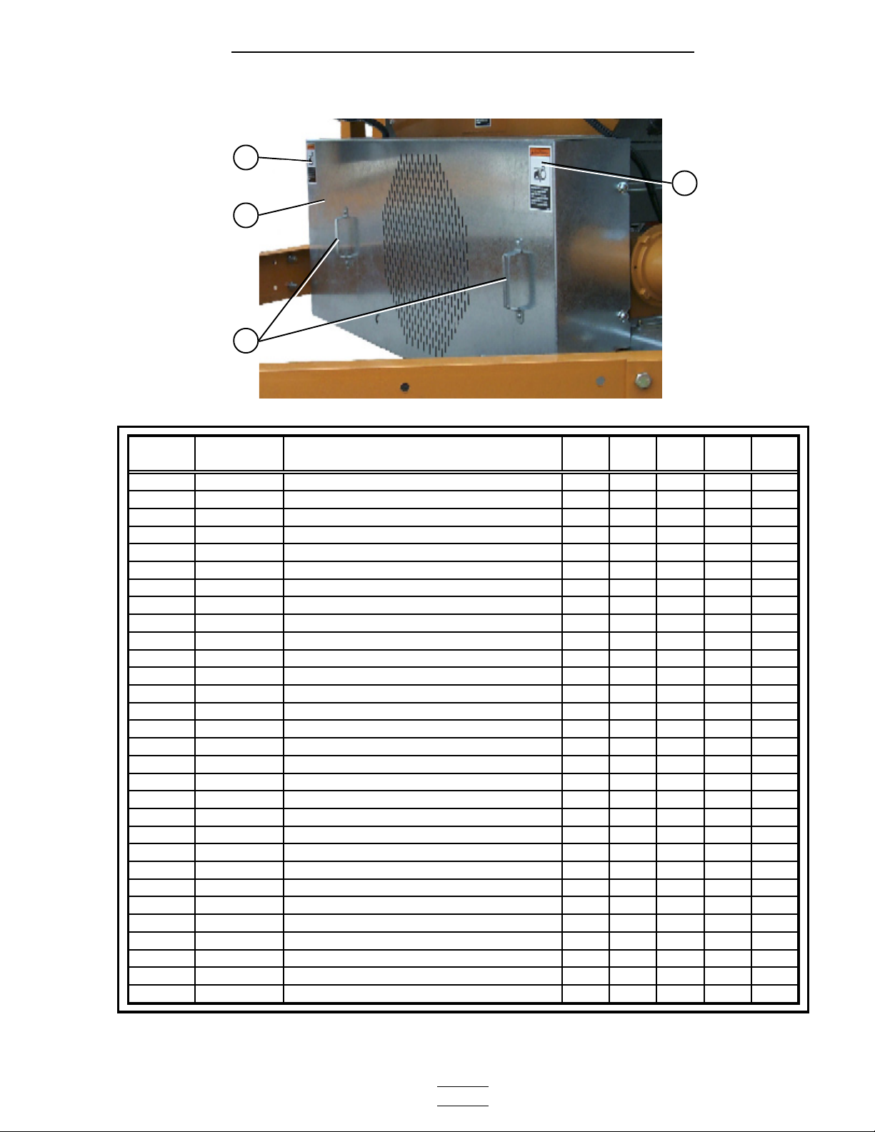
2300 Series Parts Manual Electrical (Bot. Mod.)
Air switch assembly (part # D01-0672).
Air Switch Assembly
Air switch assembly (internal parts).
3
10
11
7
9
2
8
4 5 6
1
Lower air switch assembly (installed).Upper air switch assembly (installed).
10
1-9
11
12
11
10
1-9
ITEM
No. PART No.
1-9 D01-0672 AIR SWITCH ASSEMBLY 3/DRYER
1 D01-0671
2 D01-0670
3 DC-1103
4 D03-0177
5 HF-7227
6 HF-7228
7 HF-7226
8 HF-7229
9 D03-0167
ITEM No. DESCRIPTION PART No.
AIR SWITCH BOX CONDUIT HALF
AIR SWITCH BOX FACE PLATE
DECAL, AIR PRESSURE ADJUSTMENT
GROMMET, 11/16" ID x 1" OD
COUPLING, 1/4" STD BLACK STEEL
BUSHING, 1/4" - 1/8" HEX
NIPPLE, 1/8" CLOSE
ELBOW, 1/8" - 90 SCH 40
AIR PRESSURE SWITCH
10 CONDUIT, 3/8" SEALTITE FH-7038
11 CONNECTOR, 3/8" x 90 FH-7050
12 CONNECTOR, 3/8" STRAIGHT FH-7049
DESCRIPTION
QUANTITY
2/ASSEMBLY
1/ASSEMBLY
1/ASSEMBLY
1/ASSEMBLY
1/ASSEMBLY
1/ASSEMBLY
2/ASSEMBLY
1/ASSEMBLY
1/ASSEMBLY
- 66 -
10
Page 67

2300 Series Parts Manual Electrical (Bot. Mod.)
Network Control Box
1
3
4
2
5
2
6 7 8
9
16
15
14
13
12
11 10 5
ITEM No. DESCRIPTION PART No.
1 NETWOK BOX MOUNTING CHANNEL D01-1664
2 ENCLOSURE, 12" x 10 " x 5.25" TF-1439
3 PLASTIC HOLE PLUG 1/2" DIA HH-2833
4 DECAL, NETWORK FAN/HEATER DC-1513
5 CONTROL BOARD MOUNTING PLATE TF-1426
6 CONTROL BOARD REST TF-1429A
7 DECAL, GROUND DC-1254
8 GROUND LUG FH-6634
9 FAN/HEATER NETWORK CONTROL BOARD HF-7276
10 HINGE, ALUMINUM D02-0037
11 CONTROL BOARD REST TF-1429
12 NETWORK BOX BACK PANEL TF-1428
13 TERMINAL-BLOCK ENTRELEC 4MM D01-0531
14 TERMINAL-BLANK END PROTECTOR D01-0532
15 TERMINAL-ENTRELEC END STOP D01-0533
16 TERMINAL-ENTRELEC GROUND BLOCK D01-0534
- 67 -
Page 68

2300 Series Parts Manual Electrical (Top Mod.)
Lower Junction Box with Right and Left Grain High Limits
Uper module lower junction box.
Rt Grain high limit. Lt Grain high limit.
1
2
3
4
7 5 6
Grain temperature thermister. There are
2 thermisters in each (right & left)
grain high limit thermostat assemblies.
5
6
4
3
7 1 2 8 9
- 68 -
10
Page 69

2300 Series Parts Manual Electrical (Top Mod.)
Plenum High Limit
1
11
7
12
9
Plenum high limit conduit (plenum pipe).
See page 66 for air switch
parts and page 67 for Net-
work box parts.
ITEM No. DESCRIPTION PART No.
1 HIGH LIMIT MOUNTING BRACKET D01-0254
2
2
3 CONDUIT 1/2" EMT METALLIC D03-0057
4 CONNECTOR 1/2" EMT COMPRESSION D03-0054
5 SEALTITE PVC 1/2" FH-7039
6 1/2" STRAIGHT PVC W/LOCKNUT FH-7051
7 ENCLOSURE 4x4x2.5 WHITE PVC FH-6972
8 CONNECTOR PVC 3/8" 45' W/NUT F-6913
9 SEALTITE PVC 3/8" FH-7038
10 GRAIN TEMP THERMISTOR D03-0258
11
11
12 SEAL 3/8 STRAIGHT PVC W/NUT fh-7049
13 COVER ALUMINUM, CONDUIT BODY TFC-0075
14 PLENUM THERMISTOR BOLT HF-7236
15
16 CONDUIT BODY, LL TYPE D03-0375
17 PIPE SCH 40 1/2" DM60001
18 CLAMP, BEAM 1/2" GT3-0241
19 CLAMP 1/2" CONDUIT HH-1096
the following components make up the grain high limit conduits that run through the grain colu mns. The
not shown conduit 1/2" emt metallic D03-0057
not shown
not shown
not shown
GRAIN THERMO HI-LMT 10' 210deg (for 14' dryers only)
GRAIN THERMO HI-LMT 24' 210DEG (for dryers that are 16' and longer)
PLENUM-THERMOSTAT 10' 300deg (f or 14' dryers only)
PLENUM-THERMOSTAT 24' 300DEG (f or dryers that are 16' and longer)
NUT FLANGWZ 3/8-16 ZN GR5
conduit assemblies are not shown in the photos.
connector 1/2" emt compression (2/conduit; 1 at each end of the dryer.)
coupler 1/2" emt compression (couples the lengths of 1/2" emt)
enclosure 4x4x2.5 white pvc (as of 2003 a 4x4 enclosure has been added to these
assemlies and is mounted on the rear column end panels into which thr grain
high limit thermostat conduits now terminate.)
13 14 15 16 17 18 19
D03-0005
D03-0378
D03-0004
D03-0377
S-968
D03-0054
D33-0002
FH-6972
- 69 -
Page 70

Upper junction box.
2
9
10
2300 Series Parts Manual Electrical (Top Mod.)
Upper Juntion Box / Top Auger Motor Conduit
1
8
7
Top auger motor conduit.
31
ITEM No. DESCRIPTION PART No.
1 CONDUIT 1/2" EMT METALLIC D03-0057
2 CONNECTOR 1/2" EMT COMPRESSION D03-0054
3 CLAMP 1/2" CONDUIT HH-1096
4 CONNECTOR 1/2" EMT TO SEALTITE D03-0075
5 SEALTITE PVC 1/2" FH-7039
6 ELBOW 1/2" 90 DEGREE PVC WITH FH-7052
7 1/2" STRAIGHT PVC W/LOCKNUT FH-7051
8 ENCLOSURE 4x4x2.5 WHITE PVC FH-6972
9 CONNECTOR 1/2" FH-1310
10 WIRE 18/2 TYPE SJOW-A BLACK WR-182SJOWA
11 MOUNTING PLATE WLDMNT, MERC.BX D01-0358
12 MERCURY SWITCH 6-DEG. 6" LEADS D03-0010
13 CLIP MERCURY SWITCH SPD-2098
14 MERCURY SWITCH SHAFT D01-0103
4 5 6
5
Fill switch assembly (installed).
8
9
10
11
14
Fill switch assembly (opened).
12
13
8
- 70 -
Items 8 - 14 are components of the mercury
switch box assembly (fill switch assembly),
assembly part no. D01-0192.
Page 71

2300 Series Parts Manual Electrical (Top Mod.)
Wire Way Assembly
1c
ITEM No. PART No. DESCRIPTION
1 D04-0355 WIREWAY ASSEMBLY 2000 SERIES
1A D01-1654 WIREWAY COVER SECTION-STACKDRY
1B D01-1655 WIREWAY FOR SECTIONS-STACK DRY
1C D01-1672 WIREWAY TOP CAP (SOLID)
1D D61-0106 WIREWAY BOTTOM CAP
2 FH-7040 SEALTITE PVC 1"
3 FH-7055 STRAIGHT PVC W/LOCKNUT 1"
4 FH-7056 ELBOW PVC 90DEG W/LOCKNUT 1"
5 FH-7052 ELBOW 1/2" 90 DEGREE PVC WITH
6 FH-7039 SEALTITE PVC 1/2"
QTY
1
4/ASSEMBLY
1/ASSEMBLY
1/ASSEMBLY
1/ASSEMBLY
1b
1a
5
1a
4
6
2
1a
1a
1b
1a
1d
3
2
- 71 -
Page 72

2300 Series Parts Manual Electrical (Fan Heater)
Vapor and Housing High Limits / Solenoid Conduits
Fan Heater electrical conduits.
Housing High Limit Thermostat
High Fire solenoid valve
Low Fire solenoid valve
Vapor High Limit Thermostat
1
Supply Line solenoid valve
Vapor High Limit Switch
Housing High Limit Thermostat
1
5
2
6
3
4
7
8
8
1
- 72 -
Page 73

2300 Series Parts Manual Electrical (Fan Heater)
Vapor and Housing High Limits / Solenoid Conduits
Supply line solenoid junction box.
8
7
1
Low fire solenoid valve.
9
1
8
8
High fire solenoid valve.
9
8
10
1
ITEM No. DESCRIPTION PART No.
1 SEALTITE PVC 3/8" FH-7038
2 SEAL 3/8 STRAIGHT PVC W/NUT FH-7049
3 COUPLER 1/2" SCH 40 BLK D67-0005
4 SWITCH SCREW-IN VAPOR HI-LIMIT HH-7013
5 HOUSING HI LIMIT PLATE D01-1473
6 HI-LIMIT 200 DEGREE MAN RESET THH-4020
7 UNILET TYPE LRL CONDUITBX1/2" THH-4064
NEOPRENE GASKET, CONDUIT BODY TFC-0076
COVER ALUMINUM, CONDUIT BODY TFC-0075
8 ELBOW 3/8" 90 DEGREE PVC W/NUT FH-7050
9 TEE CONLET CONDUIT BODY 1/2 TFC-0073
NEOPRENE GASKET, CONDUIT BODY TFC-0076
COVER ALUMINUM, CONDUIT BODY TFC-0075
10 CONNECTOR PVC 3/8" 45' W/NUT F-6913
1
1
NOTE: Not shown are the 1/2” close nipples (part no. THH-4032) that
connect the conduit junction boxes to the solenoid valves.
- 73 -
Page 74

2300 Series Parts Manual Control Box
Fan Heater Electrical Box
Fan Heater control box and electrical components.
1
2 3
4
5 13
12
14
6 11 7 8 9
ITEM
NUMBER PART NUMBER
1 F-942 ELECT. CONTROL BOX LID 1 1 1 1
2 CD-0005 FAN CONTROL BOX WRAPPER 26-28" 1
2 CD-0065 FAN CONTROL BOX WRAPPER 36" 1
2 CD-0193 FAN CONTROL BOX WRAPPER 40-42" 1 1
3 FH-4429-1 LATCH CONTROL BOX 2 2 2 2
4 CD-0202 FAN CONTROL BOX BOTTOM 26-28" 1
4 CD-0203 FAN CONTROL BOX BOTTOM 36-42" 1 1 1
5 HH-7048 GROMMET 1/2" OD, 3/8" ID 3 3 3 3
6 HH-7016 GROMMET 1 1/2" ID 1 1 1 1
DESCRIPTION
26" & 28" FAN
HEATERS
36" FAN
HEATERS
40" FAN
HEATERS
10
42" FAN
HEATERS
- 74 -
Page 75

2300 Series Parts Manual Control box
Fan Heater Electrical Box
ITEM
NUMBER
7 TERMINAL-BLOCK ENTRELEC 4MM D01-0531 D01-0531 D01-0531 D01-0531 D01-0531
8 TERMINAL-BLANK END PROTECTOR D01-0532 D01-0532 D01-0532 D01-0532 D01-0532
9 TERMINAL-ENTRELEC END STOP D01-0533 D01-0533 D01-0533 D01-0533 D01-0533
10 TERMINAL-ENTRELEC GRND BLOCK D01-0534 D01-0534 D01-0534 D01-0534 D01-0534
11 CONTACTOR D03-0495 D03-0494 D03-0494 D03-0492 D03-0490
12 OVERLOAD D03-0483 D03-0482 D03-0482 D03-0476 D03-0475
13 LUG GROUND,#TA-2 E160-1137 E160-1137 E160-1137 E160-1137 E160-1137
14 GRP-TRANSFORMER 2POLE IGNITION HH-1093-GRP HH-1093-GRP HH-1093-GRP HH-1093-GRP HH-1093-GRP
7 TERMINAL-BLOCK ENTRELEC 4MM D01-0531 D01-0531 D01-0531 D01-0531 D01-0531
8 TERMINAL-BLANK END PROTECTOR D01-0532 D01-0532 D01-0532 D01-0532 D01-0532
9 TERMINAL-ENTRELEC END STOP D01-0533 D01-0533 D01-0533 D01-0533 D01-0533
10 TERMINAL-ENTRELEC GRND BLOCK D01-0534 D01-0534 D01-0534 D01-0534 D01-0534
11 CONTACTOR D03-0497 D03-0494 D03-0494 D03-0492 D03-0491
12 OVERLOAD D03-0485 D03-0483 D03-0483 D03-0477 D03-0478
13 LUG GROUND,#TA-2 E160-1137 E160-1137 E160-1137 E160-1137 E160-1137
14 GRP-TRANSFORMER 2POLE IGNITION HH-1093-GRP HH-1093-GRP HH-1093-GRP HH-1093-GRP HH-1093-GRP
DESCRIPTION
10-12 HP FAN MOTORS (2612, 2812, 3612 FAN HEATERS)
220V 1Ph 208V 3Ph 220V 3Ph 440V 3Ph 575V 3Ph
10-16 HP FAN MOTORS (3615 FAN HEATERS)
220V 1Ph 208V 3Ph 220V 3Ph 440V 3Ph 575V 3Ph
10-16 HP FAN MOTORS (4015 FAN HEATERS)
220V 1Ph 208V 3Ph 220V 3Ph 440V 3Ph 575V 3Ph
7 TERMINAL-BLOCK ENTRELEC 4MM D01-0531 D01-0531 D01-0531 D01-0531 D01-0531
8 TERMINAL-BLANK END PROTECTOR D01-0532 D01-0532 D01-0532 D01-0532 D01-0532
9 TERMINAL-ENTRELEC END STOP D01-0533 D01-0533 D01-0533 D01-0533 D01-0533
10 TERMINAL-ENTRELEC GRND BLOCK D01-0534 D01-0534 D01-0534 D01-0534 D01-0534
11 CONTACTOR D03-0497 D03-0494 D03-0494 D03-0491 D03-0491
12 OVERLOAD D03-0485 D03-0483 D03-0483 D03-0478 D03-0478
13 LUG GROUND,#TA-2 E160-1137 E160-1137 E160-1137 E160-1137 E160-1137
14 GRP-TRANSFORMER 2POLE IGNITION HH-1093-GRP HH-1093-GRP HH-1093-GRP HH-1093-GRP HH-1093-GRP
20 HP FAN MOTORS (4220 FAN HEATERS)
220V 1Ph 208V 3Ph 220V 3Ph 440V 3Ph 575V 3Ph
7 TERMINAL-BLOCK ENTRELEC 4MM N/A D01-0531 D01-0531 D01-0531 D01-0531
8 TERMINAL-BLANK END PROTECTOR N/A D01-0532 D01-0532 D01-0532 D01-0532
9 TERMINAL-ENTRELEC END STOP N/A D01-0533 D01-0533 D01-0533 D01-0533
10 TERMINAL-ENTRELEC GRND BLOCK N/A D01-0534 D01-0534 D01-0534 D01-0534
11 CONTACTOR N/A D03-0495 D03-0495 D03-0492 D03-0492
12 OVERLOAD N/A D03-0484 D03-0484 D03-0480 D03-0479
13 LUG GROUND,#TA-2 N/A E160-1137 E160-1137 E160-1137 E160-1137
14 GRP-TRANSFORMER 2POLE IGNITION N/A HH-1093-GRP HH-1093-GRP HH-1093-GRP HH-1093-GRP
25 HP FAN MOTORS (4225 FAN HEATERS)
220V 1Ph 208V 3Ph 220V 3Ph 440V 3Ph 575V 3Ph
7 TERMINAL-BLOCK ENTRELEC 4MM N/A D01-0531 D01-0531 D01-0531 D01-0531
8 TERMINAL-BLANK END PROTECTOR N/A D01-0532 D01-0532 D01-0532 D01-0532
9 TERMINAL-ENTRELEC END STOP N/A D01-0533 D01-0533 D01-0533 D01-0533
10 TERMINAL-ENTRELEC GRND BLOCK N/A D01-0534 D01-0534 D01-0534 D01-0534
11 CONTACTOR N/A D03-0496 D03-0496 D03-0494 D03-0492
12 OVERLOAD N/A D03-0485 D03-0485 D03-0482 D03-0479
13 LUG GROUND,#TA-2 N/A E160-1137 E160-1137 E160-1137 E160-1137
14 GRP-TRANSFORMER 2POLE IGNITION N/A HH-1093-GRP HH-1093-GRP HH-1093-GRP HH-1093-GRP
- 75 -
Page 76

2300 Series Parts Manual Control Box
Network control panel (front).
1
Control Box Switch Panel
2
11
3
15
14
4
13
5
12
6 7 8 9 10
ITEM
NUMBER
1 DECAL, NETWORK DRYER 2 FAN MISC. DC-1521
2 HINGE 1-1/6 X 19GA SS MISC. 111-1001-2
3 SWITCH 2 POS. SELECTOR AMBER CONTROL D01-0444
4 SWITCH 2 POS. SELECTOR GREEN CONTROL D01-0446
5 SWITCH 3 POS. SELECTOR WHITE CONTROL D03-0182
6 SWITCH 2 POS. SELECTOR CLEAR CONTROL D01-0448
7 3 POS. SELECTOR SWITCH YELLOW CONTROL D01-0579
8 SWITCH 3 POS. SELECTOR BLUE CONTROL D01-0449
9 SWITCH 3 POS. SELECTOR RED CONTROL D01-0447
10 KNOB, AUGAT #PK-70B-1/4 MISC. E115-1060
11 LATCH, SOUTHCO SLOTTED MISC. TF-1519
12 SWITCH STOP BLOCK (RED) CONTROL D03-0020
13 SWITCH START N.O.(ILLUMINATED) CONTROL D03-0017
14 SWITCH 3 POS. SELECTOR AMBER CONTROL D01-0445
15 TOUCH PANEL TOP DRY AUTO MISC. TAF-6150
DESCRIPTION CIRCUIT PART NUMBER
11
- 76 -
Page 77

2300 Series Parts Manual Control box
Network control panel (rear).
1
2
3
Control Box Switch Panel (Rear)
7
6
1
Detailed view of a two
position switch.
4
5
4
ITEM
NUMBER
1 LATCH, SOUTHCO SLOTTED MISC. TF-1519
2 NETWORK DRYER DISPLAY BOARD CONTROL D03-0593
3 COMPUTER MOUNTING PLATE MISC. TF-1544
4 BLOCK, CONTACT N/O CONTROL D63-0006
5 BLOCK, LIGHT 12/24/120V LAMPS CONTROL D01-0455
6 SCR POTENTIOMETER 10K CONTROL D03-0595
7 NETWORK SWITCH PANEL MISC. D01-1668
DESCRIPTION CIRCUIT PART NUMBER
Detailed view of a
single position switch.
4
5
- 77 -
Page 78

2300 Series Parts Manual Control Box
Lower control box back panel.
1
Lower Control Box Back Panel
2
3
Emergency stop switch
(outside).
10
11
Emergency stop switch
(inside).
4
5 6 7 8 5
12
9
ITEM
NUMBER
1 FILTER RFI "B" SERIES CONTROL D03-0181
2 WIRE TIE ANCHOR MISC. D02-0039
3 WIRE TIE, 5" PANDUIT MISC. D03-0247
4 DIN RAIL, TERMINAL BLOCK MOUNTING MISC. D03-0013
5 TERMINAL - ENTRELEC END STOP MISC. D01-0533
6 TERMINAL - ENTRELEC GROUND BLOCK MISC. D01-0534
7 TERMINAL - BLOCK ENTRELEC 4MM MISC. D01-0531
8 TERMINAL - END PROTECTOR MISC. D01-0532
9 LOWER CONTROL BOX BACK PANEL MISC. D01-0486
10 EMERGENCY STOP SWITCH SAFETY TF-1279
11 DECAL, EMERGENCY STOP MISC. DC-1317
12 BLOCK, CONTACT N/C SAFETY D63-0013
DESCRIPTION CIRCUIT PART NUMBER
10
- 78 -
Page 79

2300 Series Parts Manual Control box
Upper Control Box Panel
Upper control box power distribution panel.
38
1
37
2
11
12
13
14
36
3
4
5
6
10
7
8
9
35
34
32
33
31
30
29
15
16
17
18
28
19 20 21 22 23 24 25 26 27
- 79 -
Page 80

2314 PART NUMBER
2300 Series Parts Manual Control Box
2314 Upper Control Box Panel
220V 1Ph 208V 3Ph 220V 3Ph 440V 3Ph 575V 3Ph
DESCRIPTION CIRCUIT
ITEM
NUMBER
1 POWER BOX UPPER BACK PANEL N/A D01-2087 D01-2087 D01-2087 D01-2087 D01-2087
2 POWER BOX BACK PANEL N/A D01-0480 D01-0480 D01-0480 D01-0480 D01-0480
3 OVERLOAD LOAD D03-0478 D03-0477 D03-0475 D03-0473 D03-0472
4 OVERLOAD LOAD AUX. D03-0482 D03-0480 D03-0479 D03-0475 D03-0475
5 OVERLOAD UNLOAD D03-0478 D03-0477 D03-0475 D03-0473 D03-0472
6 OVERLOAD UNLOAD AUX. D03-0482 D03-0480 D03-0479 D03-0475 D03-0475
7 CONTACTOR LOAD D03-0492 D03-0491 D03-0490 D03-0488 D03-0488
8 CONTACTOR LOAD AUX. D03-0494 D03-0493 D03-0492 D03-0490 D03-0489
9 CONTACTOR UNLOAD D03-0492 D03-0491 D03-0490 D03-0488 D03-0488
10 CONTACTOR UNLOAD AUX. D03-0494 D03-0493 D03-0492 D03-0490 D03-0489
11 TERMINAL-BLOCK ENTRELEC 4MM CONTROL D01-0531 D01-0531 D01-0531 D01-0531 D01-0531
12 TERMINAL-BLANK END PROTECTOR CONTROL D01-0532 D01-0532 D01-0532 D01-0532 D01-0532
13 TERMINAL-ENTRELEC END STOP CONTROL D01-0533 D01-0533 D01-0533 D01-0533 D01-0533
14 TERMINAL-ENTRELEC GRND BLOCK CONTROL D01-0534 D01-0534 D01-0534 D01-0534 D01-0534
15 RELAY, 3PDT 120V RH3B-U IDEC CONTROL HF-7203 HF-7203 HF-7203 HF-7203 HF-7203
16 RELAY BASE, 3PDT CONTROL 07097555 070975553 07097555 07097555 07097555
17 TRANSFORMER CONTROL FH-3807 FH-3807 FH-3807 FH-3807 FH-3807
- 80 -
18 TERMINAL GROUND BAR GROUND 006-1184-8 006-1184-8 006-1184-8 006-1184-8 006-1184-8
19 NETWORK DRYER CONTROL BOARD MOUNT PLATE N/A TF-1713 TF-1713 TF-1713 TF-1713 TF-1713
20 NETWORK DRYER CONTROL BOARD CONTROL D03-0587 D03-0587 D03-0587 D03-0587 D03-0587
21 NETWORK DRYER CONTROL BOARD COVER PLATE N/A D01-1710 D01-1710 D01-1710 D01-1710 D01-1710
22 BREAKER 6 AMP 1 POLE 110VAC CONTROL D03-0661 D03-0661 D03-0661 D03-0661 D03-0661
23 BREAKER 10 AMP 2 POLE DELAYED METER ROLL D03-0660 D03-0660 D03-0660 D03-0660 D03-0660
24 BREAKER 3 AMP 2 POLE DELAYED CONTROL D03-0726 D03-0728 D03-0726 D03-0726 D03-0726
25 SCR CONTACTOR 15 AMP 3 POLE METER ROLL D03-0106 D03-0108 D03-0106 D03-0106 D03-0106
26 SCR DRIVE BOARD BASE UNIT METER ROLL D03-0711 D03-0711 D03-0711 D03-0711 D03-0711
27 SCR ISOLATED TERMINAL BOARD METER ROLL D03-0592 D03-0592 D03-0592 D03-0592 D03-0592
28 POWER BOX CATCH ANGLE, BOTTOM N/A D01-0550 D01-0550 D01-0550 D01-0550 D01-0550
29 MAIN BREAKER POWER D01-0492 D01-0497 D01-0475 D03-0271 D03-0175
30 BREAKER UNLOAD AUX. D03-0464 D03-0461 D03-0461 D03-0545 D03-0395
31 BREAKER UNLOAD D03-0460 D03-0453 D03-0451 D03-0389 D03-0531
32 DISTRIBUTION BLOCK POWER D03-0560 D03-0560 D03-0560 D03-0560 D35-0001
33 BREAKER LOAD AUX. D03-0464 D03-0461 D03-0461 D03-0545 D03-0395
34 BREAKER LOAD D03-0460 D03-0453 D03-0451 D03-0389 D03-0531
35 BREAKER FAN 1 D03-0510 D03-0461 D03-0461 D03-0546 D03-0532
36 BREAKER FAN 2 D03-0510 D03-0461 D03-0461 D03-0546 D03-0532
37 BREAKER FAN 3 D03-0466 D03-0468 D03-0465 D03-0529 D03-0532
38 POWER BOX CATCH ANGLE, TOP N/A D01-0551 D01-0551 D01-0551 D01-0551 D01-0551
Page 81

2300 Series Parts Manual Control box
2318 PART NUMBER
2318 Upper Control Box Panel
208V 3Ph 220V 3Ph 440V 3Ph 575V 3Ph
DESCRIPTION CIRCUIT
ITEM
NUMBER
1 POWER BOX UPPER BACK PANEL N/A D01-2087 D01-2087 D01-2087 D01-2087
2 POWER BOX BACK PANEL N/A D01-0480 D01-0480 D01-0480 D01-0480
3 OVERLOAD LOAD D03-0477 D03-0475 D03-0473 D03-0472
4 OVERLOAD LOAD AUX. D03-0480 D03-0479 D03-0475 D03-0475
5 OVERLOAD UNLOAD D03-0477 D03-0475 D03-0473 D03-0472
6 OVERLOAD UNLOAD AUX. D03-0480 D03-0479 D03-0475 D03-0475
7 CONTACTOR LOAD D03-0491 D03-0490 D03-0488 D03-0488
8 CONTACTOR LOAD AUX. D03-0493 D03-0492 D03-0490 D03-0489
9 CONTACTOR UNLOAD D03-0491 D03-0490 D03-0488 D03-0488
10 CONTACTOR UNLOAD AUX. D03-0493 D03-0492 D03-0490 D03-0489
11 TERMINAL-BLOCK ENTRELEC 4MM CONTROL D01-0531 D01-0531 D01-0531 D01-0531
12 TERMINAL-BLANK END PROTECTOR CONTROL D01-0532 D01-0532 D01-0532 D01-0532
13 TERMINAL-ENTRELEC END STOP CONTROL D01-0533 D01-0533 D01-0533 D01-0533
14 TERMINAL-ENTRELEC GRND BLOCK CONTROL D01-0534 D01-0534 D01-0534 D01-0534
15 RELAY, 3PDT 120V RH3B-U IDEC CONTROL HF-7203 HF-7203 HF-7203 HF-7203
16 RELAY BASE, 3PDT CONTROL 070975553 07097555 07097555 07097555
17 TRANSFORMER CONTROL FH-3807 FH-3807 FH-3807 FH-3807
18 TERMINAL GROUND BAR GROUND 006-1184-8 006-1184-8 006-1184-8 006-1184-8
19 NETWORK DRYER CONTROL BOARD MOUNT PLATE N/A TF-1713 TF-1713 TF-1713 TF-1713
- 81 -
20 NETWORK DRYER CONTROL BOARD CONTROL D03-0587 D03-0587 D03-0587 D03-0587
21 NETWORK DRYER CONTROL BOARD COVER PLATE N/A D01-1710 D01-1710 D01-1710 D01-1710
22 BREAKER 6 AMP 1 POLE 110VAC CONTROL D03-0661 D03-0661 D03-0661 D03-0661
23 BREAKER 10 AMP 2 POLE DELAYED METER ROLL D03-0660 D03-0660 D03-0660 D03-0660
24 BREAKER 3 AMP 2 POLE DELAYED CONTROL D03-0728 D03-0726 D03-0726 D03-0726
25 SCR CONTACTOR 15 AMP 3 POLE METER ROLL D03-0108 D03-0106 D03-0106 D03-0106
26 SCR DRIVE BOARD BASE UNIT METER ROLL D03-0711 D03-0711 D03-0711 D03-0711
27 SCR ISOLATED TERMINAL BOARD METER ROLL D03-0592 D03-0592 D03-0592 D03-0592
28 POWER BOX CATCH ANGLE, BOTTOM N/A D01-0550 D01-0550 D01-0550 D01-0550
29 MAIN BREAKER POWER D01-0497 D01-0475 D03-0548 D03-0175
30 BREAKER UNLOAD AUX. D03-0461 D03-0461 D03-0545 D03-0395
31 BREAKER UNLOAD D03-0453 D03-0451 D03-0389 D03-0531
32 DISTRIBUTION BLOCK POWER D03-0560 D03-0560 D03-0560 D35-0001
33 BREAKER LOAD AUX. D03-0461 D03-0461 D03-0545 D03-0395
34 BREAKER LOAD D03-0453 D03-0451 D03-0389 D03-0531
35 BREAKER FAN 1 D03-0461 D03-0461 D03-0546 D03-0395
36 BREAKER FAN 2 D03-0461 D03-0461 D03-0546 D03-0395
37 BREAKER FAN 3 D03-0467 D03-0468 D03-0184 D03-0435
38 POWER BOX CATCH ANGLE, TOP N/A D01-0551 D01-0551 D01-0551 D01-0551
Page 82

2320 PART NUMBER
2300 Series Parts Manual Control Box
2320 Upper Control Box Panel
208V 3Ph 220V 3Ph 440V 3Ph 575V 3Ph
DESCRIPTION CIRCUIT
ITEM
NUMBER
1 POWER BOX UPPER BACK PANEL N/A D01-2087 D01-2087 D01-2087 D01-2087
2 POWER BOX BACK PANEL N/A D01-0480 D01-0480 D01-0480 D01-0480
3 OVERLOAD LOAD D03-0479 D03-0477 D03-0474 D03-0473
4 OVERLOAD LOAD AUX. D03-0483 D03-0483 D03-0477 D03-0476
5 OVERLOAD UNLOAD D03-0479 D03-0477 D03-0474 D03-0473
6 OVERLOAD UNLOAD AUX. D03-0483 D03-0483 D03-0477 D03-0476
7 CONTACTOR LOAD D03-0492 D03-0491 D03-0489 D03-0489
8 CONTACTOR LOAD AUX. D03-0494 D03-0494 D03-0492 D03-0490
9 CONTACTOR UNLOAD D03-0492 D03-0491 D03-0489 D03-0489
10 CONTACTOR UNLOAD AUX. D03-0494 D03-0494 D03-0492 D03-0490
11 TERMINAL-BLOCK ENTRELEC 4MM CONTROL D01-0531 D01-0531 D01-0531 D01-0531
12 TERMINAL-BLANK END PROTECTOR CONTROL D01-0532 D01-0532 D01-0532 D01-0532
13 TERMINAL-ENTRELEC END STOP CONTROL D01-0533 D01-0533 D01-0533 D01-0533
14 TERMINAL-ENTRELEC GRND BLOCK CONTROL D01-0534 D01-0534 D01-0534 D01-0534
15 RELAY, 3PDT 120V RH3B-U IDEC CONTROL HF-7203 HF-7203 HF-7203 HF-7203
16 RELAY BASE, 3PDT CONTROL 070975553 07097555 07097555 07097555
17 TRANSFORMER CONTROL FH-3807 FH-3807 FH-3807 FH-3807
- 82 -
18 TERMINAL GROUND BAR GROUND 006-1184-8 006-1184-8 006-1184-8 006-1184-8
19 NETWORK DRYER CONTROL BOARD MOUNT PLATE N/A TF-1713 TF-1713 TF-1713 TF-1713
20 NETWORK DRYER CONTROL BOARD CONTROL D03-0587 D03-0587 D03-0587 D03-0587
21 NETWORK DRYER CONTROL BOARD COVER PLATE N/A D01-1710 D01-1710 D01-1710 D01-1710
22 BREAKER 6 AMP 1 POLE 110VAC CONTROL D03-0661 D03-0661 D03-0661 D03-0661
23 BREAKER 10 AMP 2 POLE DELAYED METER ROLL D03-0660 D03-0660 D03-0660 D03-0660
24 BREAKER 3 AMP 2 POLE DELAYED CONTROL D03-0728 D03-0726 D03-0726 D03-0726
25 SCR CONTACTOR 15 AMP 3 POLE METER ROLL D03-0108 D03-0106 D03-0106 D03-0106
26 SCR DRIVE BOARD BASE UNIT METER ROLL D03-0711 D03-0711 D03-0711 D03-0711
27 SCR ISOLATED TERMINAL BOARD METER ROLL D03-0592 D03-0592 D03-0592 D03-0592
28 POWER BOX CATCH ANGLE, BOTTOM N/A D01-0550 D01-0550 D01-0550 D01-0550
29 MAIN BREAKER POWER D03-0657 D01-0505 D03-0535 D03-0175
30 BREAKER UNLOAD AUX. D03-0468 D03-0465 D03-0529 D03-0532
31 BREAKER UNLOAD D03-0459 D03-0457 D03-0582 D03-0531
32 DISTRIBUTION BLOCK POWER D03-0560 D03-0560 D03-0560 D35-0001
33 BREAKER LOAD AUX. D03-0468 D03-0465 D03-0529 D03-0532
34 BREAKER LOAD D03-0459 D03-0457 D03-0582 D03-0531
35 BREAKER FAN 1 D03-0468 D03-0465 D03-0529 D03-0532
36 BREAKER FAN 2 D03-0468 D03-0465 D03-0529 D03-0532
37 BREAKER FAN 3 D03-0144 D03-0467 D03-0547 D03-0141
38 POWER BOX CATCH ANGLE, TOP N/A D01-0551 D01-0551 D01-0551 D01-0551
Page 83

2300 Series Parts Manual Control box
2322 PART NUMBER
2322 Upper Control Box Panel
208V 3Ph 220V 3Ph 440V 3Ph 575V 3Ph
DESCRIPTION CIRCUIT
ITEM
NUMBER
1 POWER BOX UPPER BACK PANEL N/A D01-2087 D01-2087 D01-2087 D01-2087
2 POWER BOX BACK PANEL N/A D01-0480 D01-0480 D01-0480 D01-0480
3 OVERLOAD LOAD D03-0479 D03-0477 D03-0474 D03-0473
4 OVERLOAD LOAD AUX. D03-0483 D03-0483 D03-0477 D03-0476
5 OVERLOAD UNLOAD D03-0479 D03-0477 D03-0474 D03-0473
6 OVERLOAD UNLOAD AUX. D03-0483 D03-0483 D03-0477 D03-0476
7 CONTACTOR LOAD D03-0492 D03-0491 D03-0489 D03-0489
8 CONTACTOR LOAD AUX. D03-0494 D03-0494 D03-0492 D03-0490
9 CONTACTOR UNLOAD D03-0492 D03-0491 D03-0489 D03-0489
10 CONTACTOR UNLOAD AUX. D03-0494 D03-0494 D03-0492 D03-0490
11 TERMINAL-BLOCK ENTRELEC 4MM CONTROL D01-0531 D01-0531 D01-0531 D01-0531
12 TERMINAL-BLANK END PROTECTOR CONTROL D01-0532 D01-0532 D01-0532 D01-0532
13 TERMINAL-ENTRELEC END STOP CONTROL D01-0533 D01-0533 D01-0533 D01-0533
14 TERMINAL-ENTRELEC GRND BLOCK CONTROL D01-0534 D01-0534 D01-0534 D01-0534
15 RELAY, 3PDT 120V RH3B-U IDEC CONTROL HF-7203 HF-7203 HF-7203 HF-7203
16 RELAY BASE, 3PDT CONTROL 070975553 07097555 07097555 07097555
17 TRANSFORMER CONTROL FH-3807 FH-3807 FH-3807 FH-3807
18 TERMINAL GROUND BAR GROUND 006-1184-8 006-1184-8 006-1184-8 006-1184-8
19 NETWORK DRYER CONTROL BOARD MOUNT PLATE N/A TF-1713 TF-1713 TF-1713 TF-1713
- 83 -
20 NETWORK DRYER CONTROL BOARD CONTROL D03-0587 D03-0587 D03-0587 D03-0587
21 NETWORK DRYER CONTROL BOARD COVER PLATE N/A D01-1710 D01-1710 D01-1710 D01-1710
22 BREAKER 6 AMP 1 POLE 110VAC CONTROL D03-0661 D03-0661 D03-0661 D03-0661
23 BREAKER 10 AMP 2 POLE DELAYED METER ROLL D03-0660 D03-0660 D03-0660 D03-0660
24 BREAKER 3 AMP 2 POLE DELAYED CONTROL D03-0728 D03-0726 D03-0726 D03-0726
25 SCR CONTACTOR 15 AMP 3 POLE METER ROLL D03-0108 D03-0106 D03-0106 D03-0106
26 SCR DRIVE BOARD BASE UNIT METER ROLL D03-0711 D03-0711 D03-0711 D03-0711
27 SCR ISOLATED TERMINAL BOARD METER ROLL D03-0592 D03-0592 D03-0592 D03-0592
28 POWER BOX CATCH ANGLE, BOTTOM N/A D01-0550 D01-0550 D01-0550 D01-0550
29 MAIN BREAKER POWER D03-0657 D03-0524 D03-0535 D03-0175
30 BREAKER UNLOAD AUX. D03-0468 D03-0465 D03-0529 D03-0532
31 BREAKER UNLOAD D03-0459 D03-0457 D03-0582 D03-0531
32 DISTRIBUTION BLOCK POWER D03-0560 D03-0560 D03-0560 D35-0001
33 BREAKER LOAD AUX. D03-0468 D03-0465 D03-0529 D03-0532
34 BREAKER LOAD D03-0459 D03-0457 D03-0582 D03-0531
35 BREAKER FAN 1 D03-0468 D03-0465 D03-0529 D03-0532
36 BREAKER FAN 2 D03-0468 D03-0465 D03-0529 D03-0532
37 BREAKER FAN 3 D03-0144 D03-0144 D03-0530 D03-0141
38 POWER BOX CATCH ANGLE, TOP N/A D01-0551 D01-0551 D01-0551 D01-0551
Page 84

2300 Series Parts Manual Control Box
2326 PART NUMBER
2326 Upper Control Box Panel
208V 3Ph 220V 3Ph 440V 3Ph 575V 3Ph
DESCRIPTION CIRCUIT
ITEM
NUMBER
1 POWER BOX UPPER BACK PANEL N/A D01-2087 D01-2087 D01-2087 D01-2087
2 POWER BOX BACK PANEL N/A D01-0480 D01-0480 D01-0480 D01-0480
3 OVERLOAD LOAD D03-0480 D03-0479 D03-0475 D03-0475
4 OVERLOAD LOAD AUX. D03-0483 D03-0483 D03-0477 D03-0476
5 OVERLOAD UNLOAD D03-0480 D03-0479 D03-0475 D03-0475
6 OVERLOAD UNLOAD AUX. D03-0483 D03-0483 D03-0477 D03-0476
7 CONTACTOR LOAD D03-0493 D03-0492 D03-0490 D03-0489
8 CONTACTOR LOAD AUX. D03-0494 D03-0494 D03-0492 D03-0490
9 CONTACTOR UNLOAD D03-0493 D03-0492 D03-0490 D03-0489
10 CONTACTOR UNLOAD AUX. D03-0494 D03-0494 D03-0492 D03-0490
11 TERMINAL-BLOCK ENTRELEC 4MM CONTROL D01-0531 D01-0531 D01-0531 D01-0531
12 TERMINAL-BLANK END PROTECTOR CONTROL D01-0532 D01-0532 D01-0532 D01-0532
13 TERMINAL-ENTRELEC END STOP CONTROL D01-0533 D01-0533 D01-0533 D01-0533
14 TERMINAL-ENTRELEC GRND BLOCK CONTROL D01-0534 D01-0534 D01-0534 D01-0534
15 RELAY, 3PDT 120V RH3B-U IDEC CONTROL HF-7203 HF-7203 HF-7203 HF-7203
16 RELAY BASE, 3PDT CONTROL 070975553 07097555 07097555 07097555
17 TRANSFORMER CONTROL FH-3807 FH-3807 FH-3807 FH-3807
- 84 -
18 TERMINAL GROUND BAR GROUND 006-1184-8 006-1184-8 006-1184-8 006-1184-8
19 NETWORK DRYER CONTROL BOARD MOUNT PLATE N/A TF-1713 TF-1713 TF-1713 TF-1713
20 NETWORK DRYER CONTROL BOARD CONTROL D03-0587 D03-0587 D03-0587 D03-0587
21 NETWORK DRYER CONTROL BOARD COVER PLATE N/A D01-1710 D01-1710 D01-1710 D01-1710
22 BREAKER 6 AMP 1 POLE 110VAC CONTROL D03-0661 D03-0661 D03-0661 D03-0661
23 BREAKER 10 AMP 2 POLE DELAYED METER ROLL D03-0660 D03-0660 D03-0660 D03-0660
24 BREAKER 3 AMP 2 POLE DELAYED CONTROL D03-0728 D03-0726 D03-0726 D03-0726
25 SCR CONTACTOR 15 AMP 3 POLE METER ROLL D03-0108 D03-0106 D03-0106 D03-0106
26 SCR DRIVE BOARD BASE UNIT METER ROLL D03-0711 D03-0711 D03-0711 D03-0711
27 SCR ISOLATED TERMINAL BOARD METER ROLL D03-0592 D03-0592 D03-0592 D03-0592
28 POWER BOX CATCH ANGLE, BOTTOM N/A D01-0550 D01-0550 D01-0550 D01-0550
29 MAIN BREAKER POWER D03-0686 D03-0686 D01-0634 D03-0572
30 BREAKER UNLOAD AUX. D03-0468 D03-0465 D03-0529 D03-0532
31 BREAKER UNLOAD D03-0461 D03-0461 D03-0545 D03-0395
32 DISTRIBUTION BLOCK POWER D03-0560 D03-0560 D03-0560 D35-0001
33 BREAKER LOAD AUX. D03-0468 D03-0465 D03-0529 D03-0532
34 BREAKER LOAD D03-0461 D03-0461 D03-0545 D03-0395
35 BREAKER FAN 1 D03-0144 D03-0467 D03-0547 D03-0141
36 BREAKER FAN 2 D03-0144 D03-0467 D03-0547 D03-0141
37 BREAKER FAN 3 D01-0499 D01-0500 D03-0140 D03-0418
38 POWER BOX CATCH ANGLE, TOP N/A D01-0551 D01-0551 D01-0551 D01-0551
Page 85

NOTES
- 85 -
Page 86

NOTES
- 86 -
Page 87

NOTES
- 87 -
Page 88

1004 E. Illinois St., Box 20
Assumption, IL 62510-0020
phone: 217-226-4421
fax: 217-226-4498
May 2004
 Loading...