

Page 1
PNEG-1366
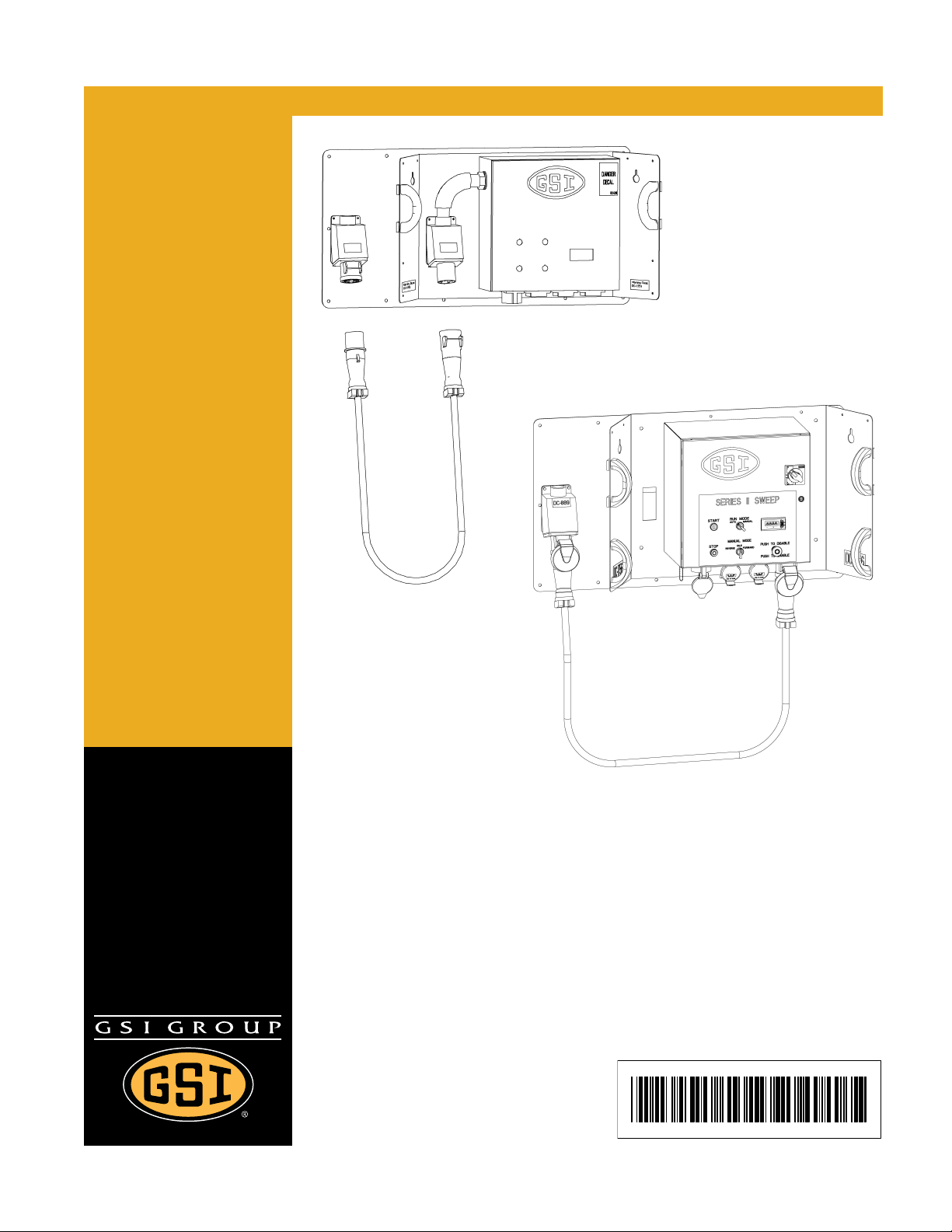
12" and 16" Series II Sweep
Quick Disconnect Control Box Kit
Owner ’s Manual
PNEG-1366
Date: 10-11-10
Page 2

Model Number :
Personnel operating or working around this equipment should read this manual. This manual
must be delivered with equipment to its owner. Failure to read this manual and its safety
instructions is a misuse of the equipment. Any misuse of the equipment may void the warranty.
Date Delivered:
Date Installed:
Notes:
2 PNEG-1366 12" and 16" Series II Sweep Quick Disconnect Control Box Kit
Page 3

Table of Contents
Contents
Chapter 1 Product Overview .................................................................................................................................5
Chapter 2 Safety .....................................................................................................................................................6
Safety Guidelines ............ .... .................................................................................................................. 6
Safety Instructions ..................... ... .... ................................................... ... .... ... ... ... .... .............................. 7
Operator Qualifications ....................................... ... ... .... ... ... ... .... ... ... ................................................... 11
Chapter 3 Decals ..................................................................................................................................................12
Chapter 4 Introduction ........................................................................................................................................15
General Information ............................................................................................................................ 15
Capacities and Specifications ............................................................................................................. 16
Chapter 5 Assembly ............................................................................................................................................18
Docking Station Mount ........................................................................................................................ 18
Control Panel Conduit Hole (Pre-June 2010) ...................................................................................... 19
Control Panel Installation .................................................................................................................... 20
Control Panel Receptacle Mounting (Current Style Panel) ................................................................. 20
Control Panel and Receptacle Installation .......................................................................................... 20
Guidance Handle Installation .............................................................................................................. 22
Place Control Panel Into Docking Station ........................................................................................... 24
Control Panel Setup ............................................................................................................................ 25
Calibration ........................................................................................ ................................................... 30
Operation ............................................................................................................................................ 31
Chapter 6 Start-Up ...............................................................................................................................................32
Perform Pre-Start Checks ................................................... ... .... ... ... ... ... ............................................. 32
Start the Auger .................................................................................................................................... 33
Chapter 7 Operation ............................................................................................................................................34
Operating the Sweep Auger ................................................ ... .... ... ... ... ................................................ 34
Operating the Sweep Auger Control Panel ......................................................................................... 35
Chapter 8 Shut Down ...........................................................................................................................................36
Normal Shut Down .............................................................................................................................. 36
Emergency Shut Down ............................................. .... ... ... ... .... ......................................................... 36
Storage Preparation ............ ................................................... .... ... ... ... ... .... ......................................... 36
Chapter 9 Maintenance ........................................................................................................................................37
Maintain the Auger .............................................................................................................................. 37
Chapter 10 Control Panel Diagrams ...................................................................................................................38
Series II Sweep Control Package - 08-32A:3-12A, Non-575V (S2PFA) ........................................... 38
Series II Sweep Control Package - 30-40A:3-12A, Non-575V (S2PFB) ........................................... 39
Series II Sweep Control Package - 08-32A:3-12A, 575V Only (S2PFC) ........................................... 40
Control Panel Schematic (460/3/60) Pre-June 2010 ......................................................................... 41
Control Panel Schematic (230/3/60) Pre-June 2010 ......................................................................... 42
Control Panel Schematic (380/3/50) Pre-June 2010 ......................................................................... 43
Chapter 11 Troubleshooting ...............................................................................................................................44
PNEG-1366 12" and 16" Series II Sweep Quick Disconnect Control Box Kit 3
Page 4

Table of Contents
Chapter 12 Parts List ...........................................................................................................................................45
Control Panel Components Pre-June 2010 Style Panel .................................................................... 46
Quick Detach Control Panel Assembly (GC10115) Pre-June 2010 .................................................. 48
Control Box Base Assembly (GC10109) (for Quick Detach Control Panel) Pre-June 2010 .............. 49
Dock Station Assembly (GC10116) (for Quick Detach Control Panel) Pre-June 2010 ..................... 50
Conduit Assembly (GC10113) (for Quick Detach Control Panel) ...................................................... 51
Drop Cord Assembly (GC10079) (for Quick Detach Control Panel) Pre-June 2010 ....................... .. 52
Quick Detach Control Panel Receptacles Parts ................................................................................ 53
Quick Detach Control Panel Package (GK80112) ............................................................................. 54
Lift Base Panel Assembly (GK80108) ............................................................................................... 55
Lift Base Dock Assembly (GK80110) .... ... ... .... ... ... ... .... ... ... ... .... ... ... ... ... ............................................ 56
Drop Cord Assembly (GK80111) ....................................................................................................... 57
Chapter 13 Warranty ............................................................................................................................................59
4 PNEG-1366 12" and 16" Series II Sweep Quick Disconnect Control Box Kit
Page 5
1. Product Overview
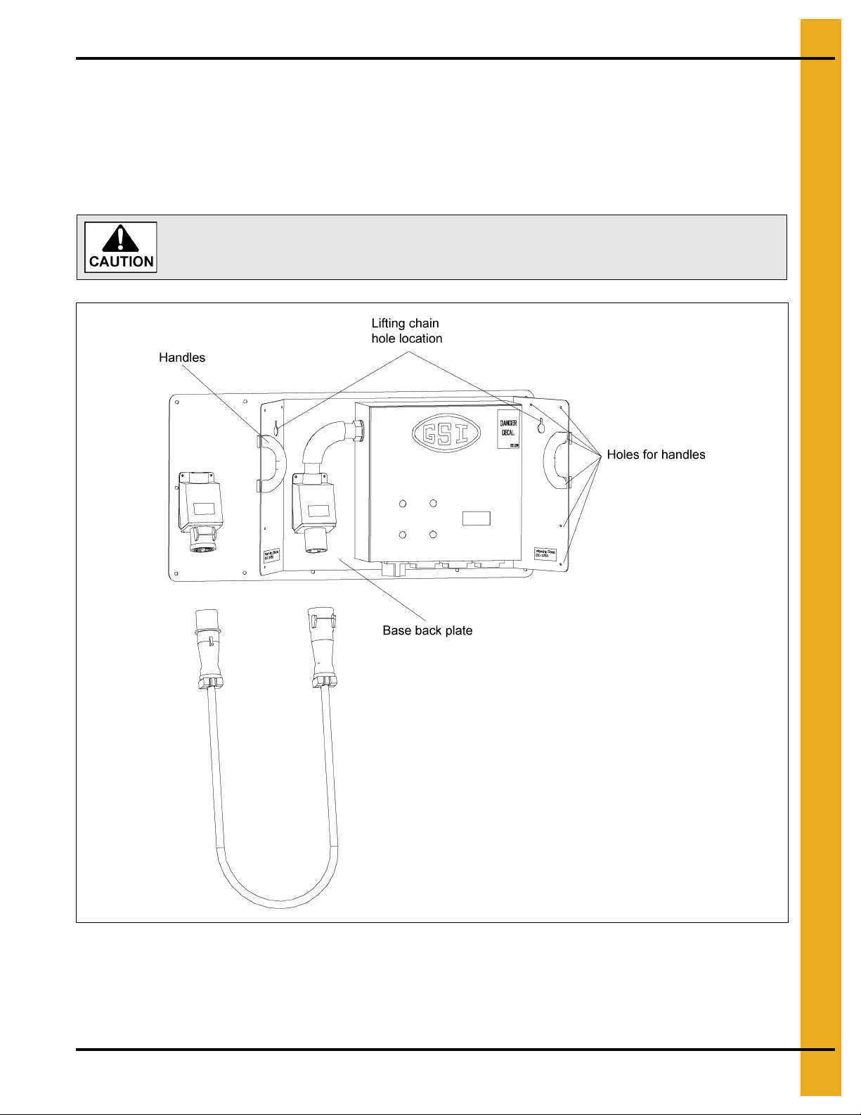
Never attempt to lift the control box by yourself. Always use two (2) or more
persons with proper lifting equipment.
The Quick Disconnect Control Box was designed to work 12" and 16" GSI Series II Sweeps.This Quick
Disconnect Control Box modular design will allow you to move the control box to each sweep location,
therefore only one control box is needed to control all of the same size sweeps. Each sweep location
will require a docking station for the control box base to slide into. The control box base is supplied with
four (4) handles for manual lifting. These handles can be installed in any of the holes located on the
outside edges of the base back plate. The base back plate also has two (2) chain lift holes for
mechanical hoisting.
Figure 1A
PNEG-1366 12" and 16" Series II Sweep Quick Disconnect Control Box Kit 5
Page 6
2. Safety
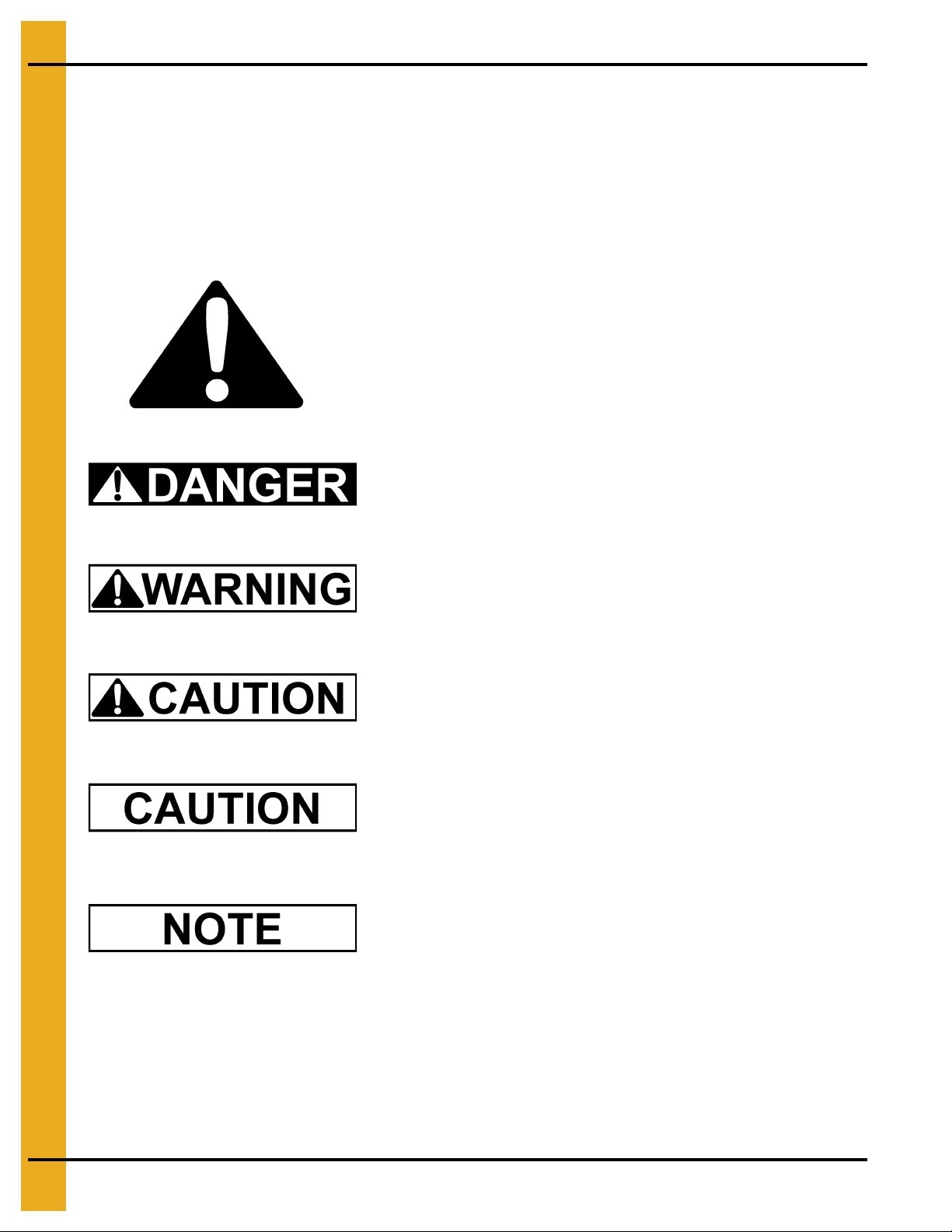
This is the safety alert symbol. It is used to alert you
to potential personal injury hazards. Obey all safety
messages that follow this symbol to avoid possible
injury or death.
WARNING indicates a potentially hazardous situation
which, if not avoided, could result in death or serious injury.
CAUTION indicates a potentially hazardous situation which,
if not avoided, may result in minor or moderate injury.
CAUTION used without the safety alert symbol indicates a
potentially hazardous situation which, if not avoided, may
result in property damage.
NOTE indicates information about the equipment that you
should pay special attention.
DANGER indicates an imminently hazardous situation
which, if not avoided, will result in death or serious injury.
Safety Guidelines
This manual contains information that is important for you, the owner/operator, to know and understand.
This information relates to protecting personal safety and preventing equipment problems. It is the
responsibility of the owner/operator to inform anyone operating or working in the area of this equipment
of these safety guidelines. To help you recognize this information, we use the symbols that are defined
below. Please read the manual and pay attention to these sections. Failure to read this manual and its
safety instructions is a misuse of the equipment and may lead to serious injury or death.
6 PNEG-1366 12" and 16" Series II Sweep Quick Disconnect Control Box Kit
Page 7
2. Safety
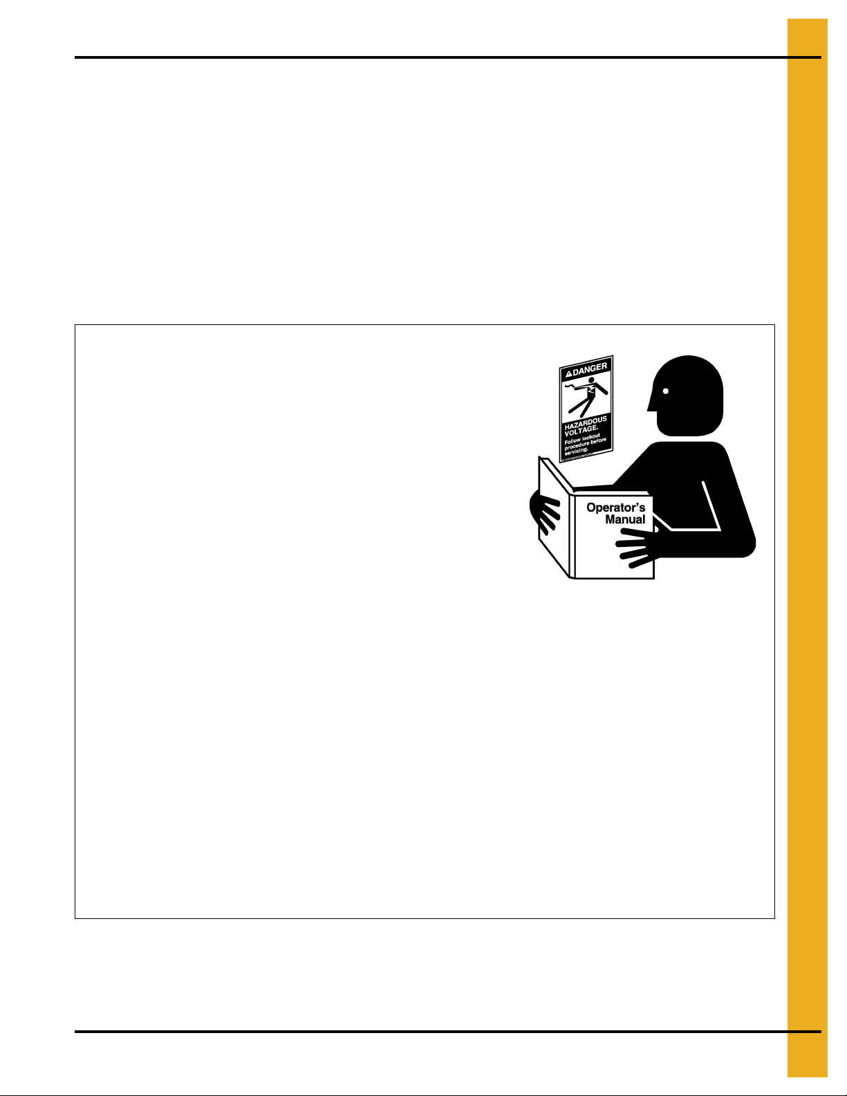
Follow Safety Instructions
Carefully read all safety messages in this manual and
safety signs on your equipment. Keep signs in good
condition. Replace missing or damaged safety signs.
Be sure new equipment components and repair parts
include the current safety signs. Replacement safety signs
are available from the manufacturer.
Learn how to operate the machine and how to use controls
properly. Do not let anyone operate without instruction.
Keep unqualified personnel out of the work area at
ALL times.
Keep your machinery in proper working condition.
Unauthorized modifications to the machine may impair
the function and/or safety and affect machine life.
Never work alone.
Never start equipment until all personnel are clear of the
work area.
Never attempt to assist machinery or try to remove trash
from equipment while in operation.
Keep all guards in place during operation.
Always lock out power to equipment when work is finished.
If you do not understand any part of this manual and need
assistance, contact your dealer.
Read ALL Safety Information
and Instructions before
Operating Machinery.
Safety Instructions
Our foremost concern is your safety and the safety of others associated with this equipment. We want to
keep you as a customer. This manual is to help you understand safe operating procedures and some
problems which may be encountered by the operator and other personnel.
As owner and/or operator, it is your responsibility to know what requirements, hazards and precautions
exist, and to inform all personnel associated with the equipment or in the area. Safety precautions may be
required from the personnel. Avoid any alterations to the equipment. Such alterations may produce a very
dangerous situation where SERIOUS INJURY or DEATH may occur.
This equipment shall be installed in accordance with the current installation codes and applicable
regulations which should be carefully followed in all cases. Authorities having jurisdiction should be
consulted before installations are made.
PNEG-1366 12" and 16" Series II Sweep Quick Disconnect Control Box Kit 7
Page 8
2. Safety
Lifting Hazard
Do not lift equipment without personal or mechanical
assistance. Single person lift could cause injury.
To avoid muscle strain or back injury, use lifting aids and
proper lifting techniques when removing or replacing the
control box.
Use Proper Lifting
Equipment
Install and Operate Equipment Properly
This equipment shall be installed in accordance with the
current installation codes and applicable regulations which
should be carefully followed in all cases. Authorities having
jurisdiction should be consulted before installations
are made.
Electrical controls should be installed by a qualified
electrician and must meet standards set by the national
electrical code and all local and state codes.
A main power disconnect switch capable of being locked
only in the OFF position should be used. The Disconnect
must be LOCKED in the OFF position before unplugging
either end of the power cord.
Electric Shock Hazard
8 PNEG-1366 12" and 16" Series II Sweep Quick Disconnect Control Box Kit
Page 9
2. Safety
Practice Safe Maintenance
Lock Out
Power
Keep Work
Area Clean
Replace
Guards
Never lubricate, service, or adjust machine while it is in
operation. Keep hands, feet, and clothing from rotating
parts. Replace all guards.
Keep all parts in good condition and properly installed.
Fix damage immediately. Replace worn or broken
parts. Remove any build up grease, oil, or debris.
Understand service procedures before doing work.
Keep area clean and dry.
ALWAYS turn off and lock out all power sources before
performing any maintenance.
Prepare for Emergencies
Be prepared if fire starts.
Keep a first aid kit and fire extinguisher handy.
Keep emergency numbers for doctors, ambulance service,
hospital and fire department near your telephone.
Keep Emergency Equipment
Quickly Accessible
PNEG-1366 12" and 16" Series II Sweep Quick Disconnect Control Box Kit 9
Page 10
2. Safety
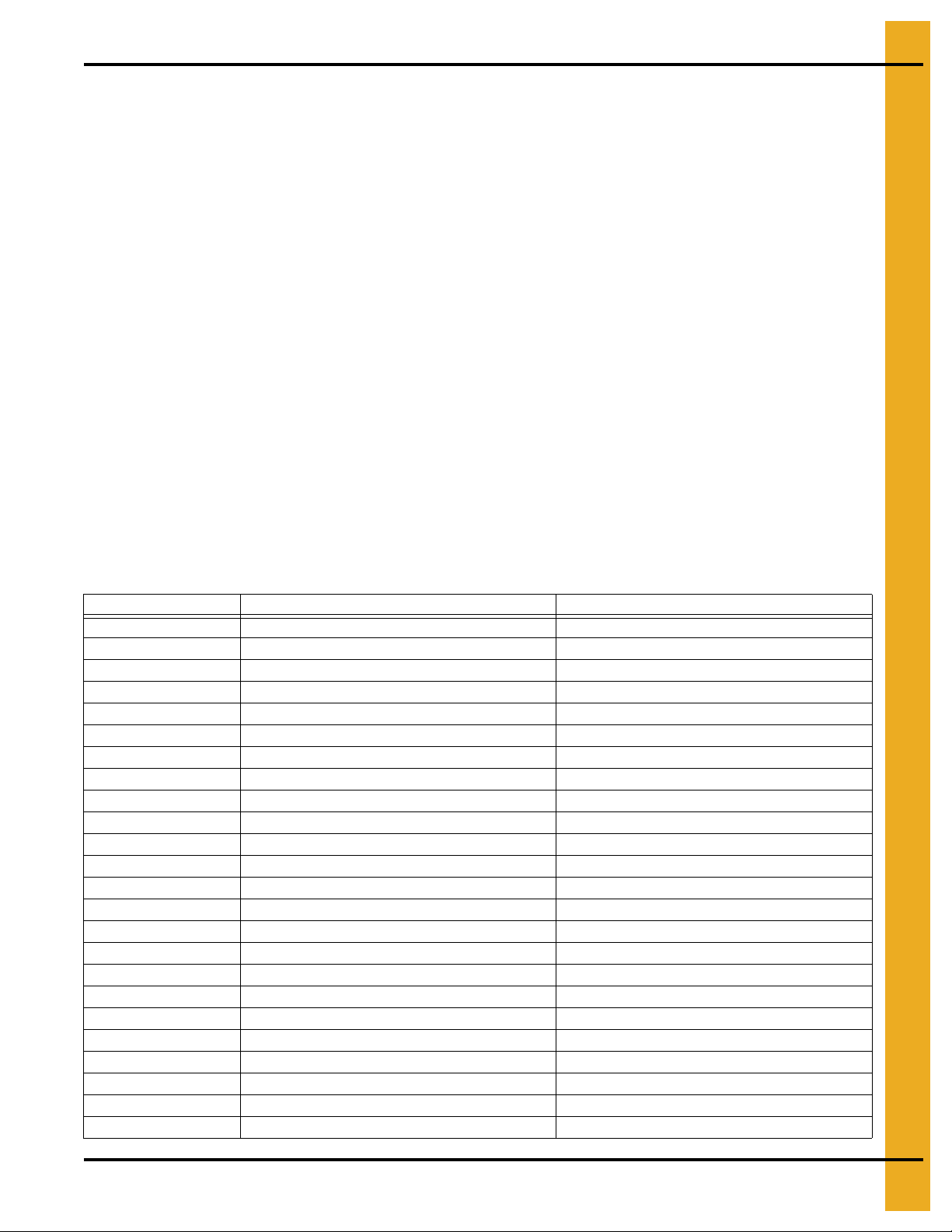
Wear Protective Clothing
Wear close fitting clothing and safety equipment appropriate
to the job.
Remove all jewelry.
Long hair should be tied up and back.
Safety glasses should be worn at all times to protect eyes
from debris.
Wear gloves to protect your hands from sharp edges on
plastic or steel parts.
Wear steel toe boots to help protect your feet from falling
debris. Tuck in any loose or dangling shoe strings.
A respirator may be needed to prevent breathing potentially
toxic fumes and dust.
Wear hard hat to help protect your head.
Wear appropriate fall protection equipment when working at
elevations greater than six feet (6').
Eye Protection
Gloves
Steel Toe Boots
Respirator
Hard Hat
Fall Protection
10 PNEG-1366 12" and 16" Series II Sweep Quick Disconnect Control Box Kit
Page 11
2. Safety
Operator Qualifications
A. The User/Operator must be competent and experienced to operate auger equipment. Anyone who
works with or around augers must have good common sense in order to be qualified. T hese persons
must also know and meet all other qualifications, such as:
i. Any person who has not read and/or does not understand all operation and safety procedures
is not qualified to operate any auger systems.
ii. Certain regulations apply to personnel operating power machinery. Personnel under the age of
18 years may not operate power machinery, including augers. It is your responsibility, as owner
and/or supervisor, to know what these regulations are in your area or situation.
iii. Unqualified or incompetent persons are to remain out of the work area.
iv. O.S.H.A. (Occupational Safety and Health Administration) regulations state: “At the time of
initial assignment and at least annually thereafter, the employer shall instruct every employee
in the safe operation and servicing of all equipment with which the employee is, or will be
involved”. (Federal Occupational Safety and Health Standards for Agriculture. Subpart D,
Section 1928.57 (a) (6)).
B. As a requirement of O.S.H.A., it is necessary for the employer to train the employee in the safe
operating and safety procedures for this auger. The sign-off sheet is provided for your convenience
and personal record keeping. All unqualified persons are to stay out of the work area at all times. It
is strongly recommended that another qualified person who knows the shut down procedure is in the
area in the event of an emergency.
Date Employee Name Supervisor Name
PNEG-1366 12" and 16" Series II Sweep Quick Disconnect Control Box Kit 11
Page 12
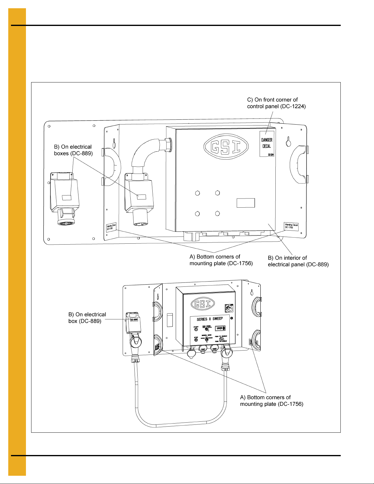
3. Decals
Figure 3A shows the location of the decals and safety signs which should appear on the Cont rol Panel and
Quick Disconnect Control Kit.
NOTE: Please remember safety signs provide important safety information for people working near bin
unloading equipment that is in operation. Any safety signs that are worn, missing, illegible or
painted over should be replaced immediately. Obtain FREE replacements by contacting GSI.
Figure 3A Control Panel Located Outside of Bin
12 PNEG-1366 12" and 16" Series II Sweep Quick Disconnect Control Box Kit
Page 13
3. Decals
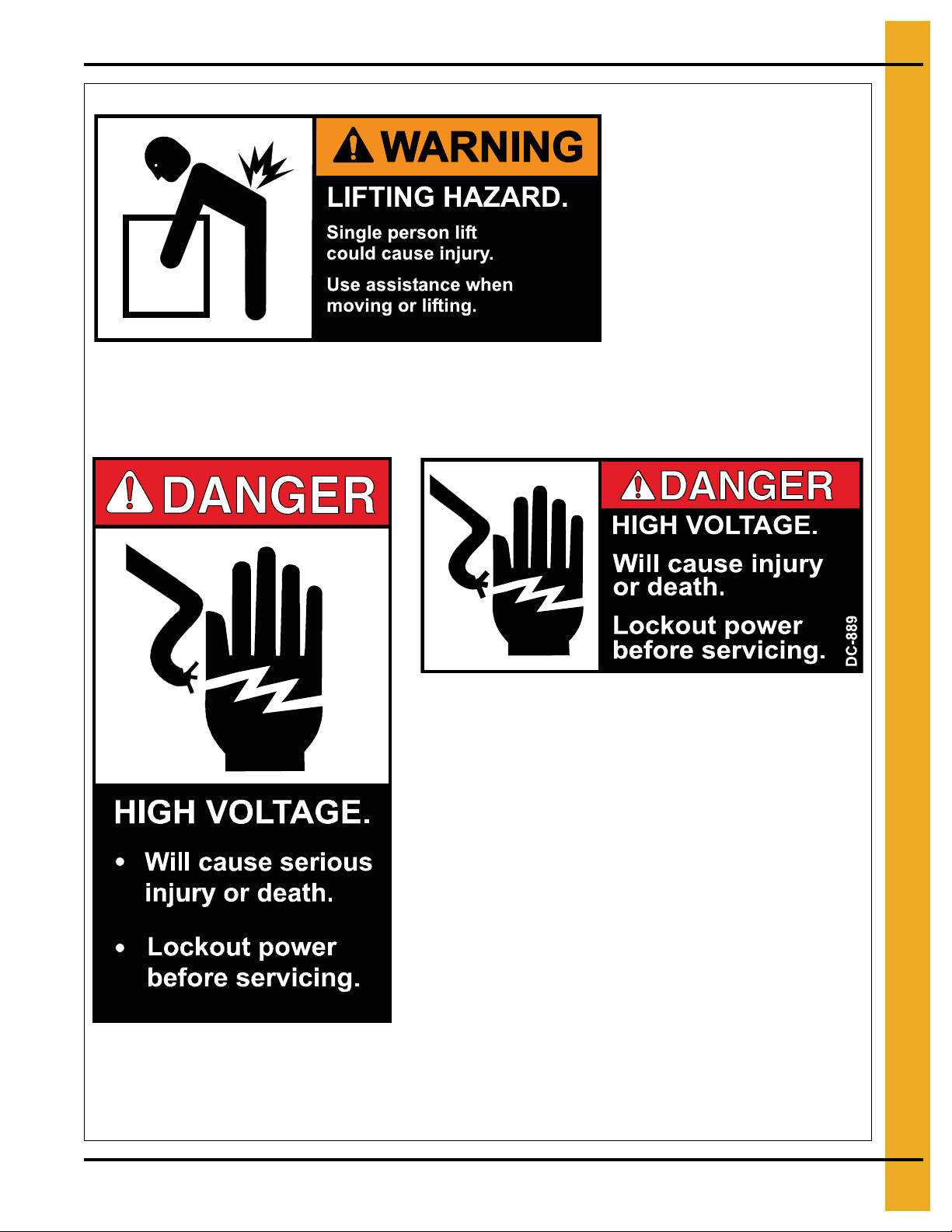
DC-1756
A) DC-1756
Location: Corners of mounting plate.
Size: 4-3/4" x 2-1/4"
DC-1756
DC-889
B) DC-889
Location: Interior of control panel. On electrical boxes.
Size: 2-13/16" x 1-7/16"
DC-1224
C) DC-1224
Location: Corner of control panel.
Size: 2-7/8" x 5"
DC-1224
PNEG-1366 12" and 16" Series II Sweep Quick Disconnect Control Box Kit 13
Page 14
3. Decals
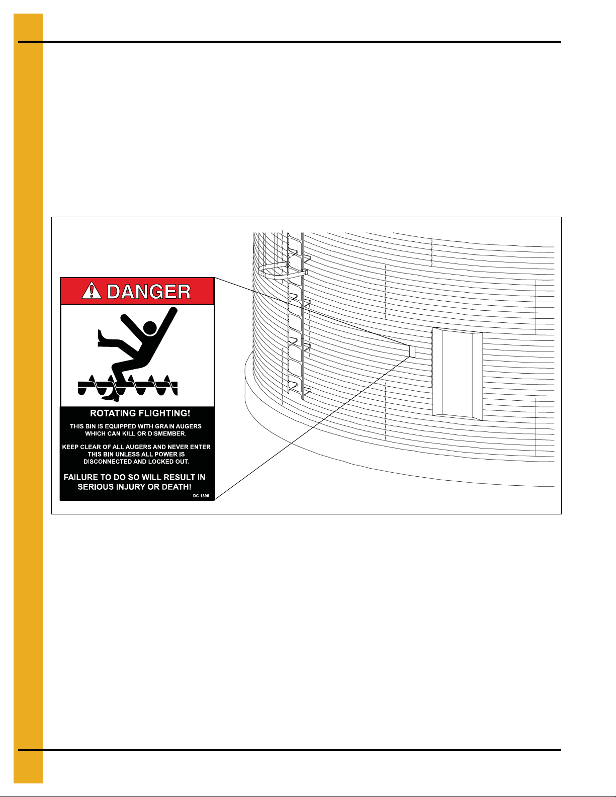
A. DANGER Sign No. DC-1395 was supplied with your bin unloading equipment. This safety sign
should be applied to the side of the bin near the bin opening, so it will be viewed by people
entering into the bin storage building. Do not cover any safety signs or any other signs that are
already there.
B. If the safety sign location suggested is not in full view because of equipment modifications, other
equipment in the area or any reason, then locate the safety sign in a more suitable location.
C. Be certain the surface is clean, dry and free of dirt and oil. Peel paper backing from decals and stick
into place. The adhesive backing will bond on contact.
NOTE: Please remember, safety signs provide important safety information for people working near bin
unloading equipment that is in operation.
NOTE: If the Safety Sign cannot be easily read for any reason or has been painted over, replace it
immediately. Additional Safety Signs may be obtained free of charge from your dealer, distributor
or ordered from the factory.
Order SAFETY SIGN NO. DC-1395
14 PNEG-1366 12" and 16" Series II Sweep Quick Disconnect Control Box Kit
Page 15

4. Introduction
NEVER enter a grain bin unless ALL power driven equipment has been shut down.
Disconnect and lock out power before entering the bin or servicing the equipment.
General Information
1. GSI reserves the right to improve its product whenever possible and practical to do so. We reserve
the right to change, improve and modify products at any time without obligation to make changes,
improvements and modifications on equipment sold previously.
2. This bin sweep auger has been engineered and manufactured to give years of dependable service .
The care and maintenance of this equipment will affect the satisfaction and service obtained. By
following the instructions and suggestions recommended, the owner should receive quality service
for many years. If additional information or assistance should be required, please contact GSI.
3. It is important to check both the quantity of parts and their descriptions with the packing list enclosed
within each package. All claims for freight damage or shortage must be made by the consignee within
ten (10) days from the date of the occurrence of freight damage. The consignee should accept the
shipment after noting the damage or loss.
PNEG-1366 12" and 16" Series II Sweep Quick Disconnect Control Box Kit 15
Page 16
4. Introduction
Electrical controls and wiring should be installed by a qualified electrician. The
motor disconnect switches and conductor cables should comply with the National
Electrical code and any local codes which apply. Reset and motor starting
stations should be located so the operator can see that all personnel are clear
of the equipment.
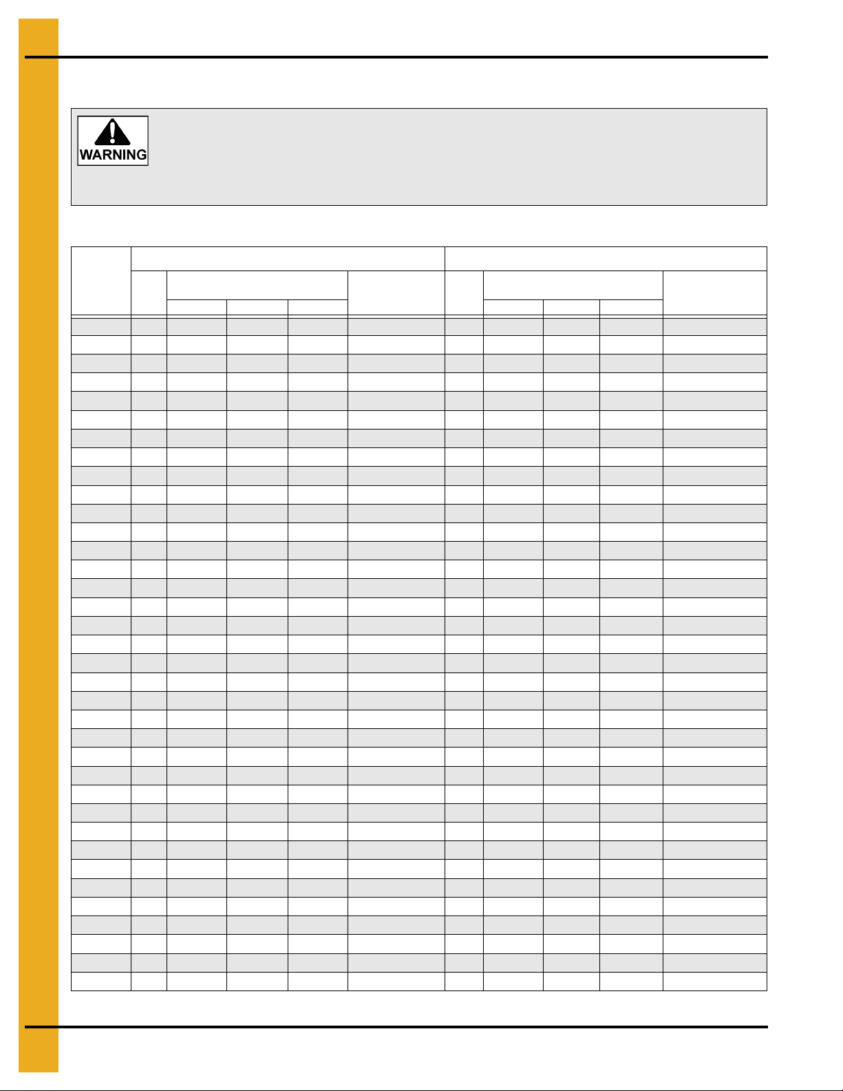
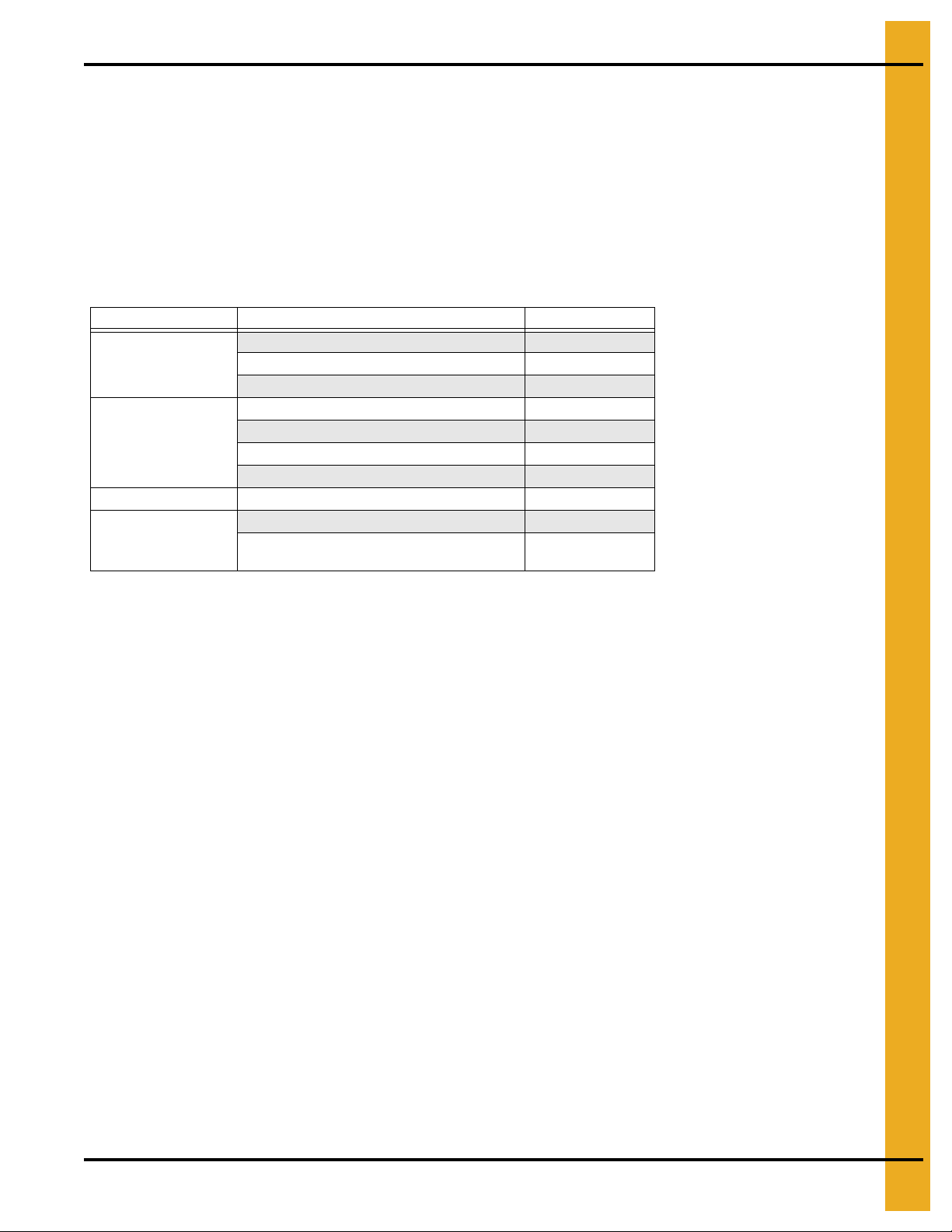
Capacities and Specifications
1. Use the Chart below to determine the horsepower required.
12" Series II Sweep 16" Series II Sweep
Bin
Diameter
36' 2 7.5 7.5 7.5 16.79' (5.12 m) 2 7.5 7.5 7.5 16.85' (5.14 m)
37' 2 7.5 7.5 7.5 17.79' (5.43 m) 2 7.5 7.5 7.5 16.85' (5.14 m)
39' 2 7.5 7.5 7.5 18.79' (5.73 m) 2 7.5 7.5 7.5 17.85' (5.44 m)
40' 2 7.5 7.5 7.5 18.79' (5.73 m) 2 7.5 7.5 7.5 18.75' (5.72 m)
42' 2 7.5 7.5 7.5 19.79' (6.04 m) 2 7.5 7.5 10 19.85' (6.05 m)
43' 2 7.5 7.5 7.5 20.79' (6.34 m) 2 7.5 7.5 10 19.85' (6.05 m)
45' 2 7.5 7.5 7.5 20.79' (6.34 m) 2 7.5 7.5 10 20.85' (6.36 m)
48' 2 7.5 7.5 7.5 22.79' (6.95 m) 2 7.5 10 10 22.85' (6.96 m)
49' 2 7.5 7.5 7.5 22.79' (6.95 m) 2 7.5 10 10 22.85' (6.96 m)
51' 2 7.5 7.5 10 23.79' (7.26 m) 2 7.5 10 10 23.85' (7.27 m)
54' 2 7.5 7.5 10 25.79' (7.86 m) 2 10 10 10 25.85' (7.88 m)
55' 2 7.5 7.5 10 25.79' (7.86 m) 2 10 10 10 25.85' (7.88 m)
57' 2 7.5 7.5 10 26.79' (8.17 m) 2 10 10 10 26.85' (8.18 m)
59' 2 7.5 7.5 10 27.79' (8.47 m) 2 10 10 15 27.85' (8.49 m)
60' 2 7.5 7.5 10 28.79' (8.78 m) 2 10 10 15 28.85' (8.79 m)
62' 2 7.5 7.5 10 29.79' (9.08 m) 2 10 10 15 29.85' (9.10 m)
63' 2 7.5 7.5 10 29.79' (9.08 m) 2 10 10 15 29.85' (9.10 m)
66' 2 7.5 7.5 10 31.79' (9.69 m) 2 10 15 15 31.85' (9.71 m)
68' 2 7.5 7.5 10 32.79' (10.00 m) 2 10 15 15 32.85' (10.01 m)
69' 2 7.5 7.5 10 32.79' (10.00 m) 2 10 15 15 32.85' (10.01 m)
72' 2 7.5 7.5 10 34.79' (10.61 m) 2 15 15 15 34.85' (10.62 m)
75' 2 10 10 10 35.79' (10.91 m) 2 15 15 15 35.85' (10.93 m)
78' 2 10 10 10 37.79' (11.52 m) 2 15 15 15 37.85' (11.54 m)
80' 2 10 10 10 38.79' (11.83 m) 2 15 15 15 38.85' (11.84 m)
81' 2 10 10 10 38.79' (11.83 m) 2 15 15 15 38.85' (11.84 m)
84' 2 10 10 15 40.79' (12.44 m) 2 15 15 15 40.85' (12.45 m)
87' 2 10 10 15 41.79' (12.74 m) 2 15 15 20 41.85' (12.76 m)
88' 2 10 10 15 42.79' (13.05 m) 2 15 15 20 42.85' (13.06 m)
90' 2 10 10 15 43.79' (13.35 m) 2 15 15 20 43.85' (13.37 m)
91' 2 10 10 15 43.79' (13.35 m) 2 15 15 20 43.85' (13.37 m)
92' 2 10 10 15 44.79' (13.66 m) 2 15 20 20 44.85' (13.67 m)
95' 2 10 15 15 45.79' (13.97 m) 2 15 20 20 45.85' (13.98 m)
98' 2 10 15 15 47.79' (14.57 m) 2 15 20 20 47.85' (14.58 m)
105' 3 15 15 20 50.79' (15.48 m) 3 20 20 20 50.85' (15.50 m)
113' 3 15 15 20 54.79' (16.70 m) 3 20 20 20 54.85' (16.72 m)
120' 3 15 15 20 58.79' (17.92 m) 3 20 20 20 58.85' (17.94 m)
Due to continual improvements, GSI designs and specifications are subject to change without notice.
Drive
HP
16 PNEG-1366 12" and 16" Series II Sweep Quick Disconnect Control Box Kit
Bushel/MT per Hour
Horsepower
5000/125 6000/155 7000/180 8000/205 9000/230 10000/255
Length
Pivot to End
Drive
HP
Bushel/MT per Hour
Horsepower
Length
Pivot to End
Page 17
4. Introduction
There should ALWAYS be two (2) people in the work area.
A main power disconnect switch capable of being locked only in the OFF position
should be used. The disconnect must be locked in the off position before
unplugging either end of the cord. It should also be locked whenever work is
being done on the Series II Sweep. This has been integrated into the control panel
after June of 2010.
NOTE: The horsepower recommendations are for augering reasonably dry grain. High moisture grain
(greater than 15%) will require greater power for maximum capacity. The maximum capacity will
be less with high moisture grain than with dry grain.
Sweep drive and carrier wheels require plates or track over aeration flooring for travel and supports
not supplied with the sweep unit. Contact your installer or flooring provider for possible source
and details.
2. A magnetic starter should be used to protect the motor when starting and stopping. It should stop
the motor in case of power interruption, conductor fault, low voltage, circuit interruption or motor
overload. The motor must be restarted manually. Some motors have built-in thermal overload
protection. If this is the type of motor being used, use only those with a manual reset.
3. The motor starting controls must be located outside the bin. They must NEVER be installed on the
Series II auger inside the bin.
4. Disconnect and lock out the power before resetting motor overloads.
5. Disconnect and lock out the power before entering the bin.
6. Disconnect and lock out the power before servicing the equipment.
7. Position the reset and motor starting controls so that the operators have full view of the equipment.
8. Make sure electric motors are grounded.
PNEG-1366 12" and 16" Series II Sweep Quick Disconnect Control Box Kit 17
Page 18
5. Assembly
The control panel must be mounted outside the bin near the door. The foot switch
has to be plugged into the control panel and depressed before the sweep is
operational. It has a 10' cord so the sweep can only be monitored from outside
the bin.
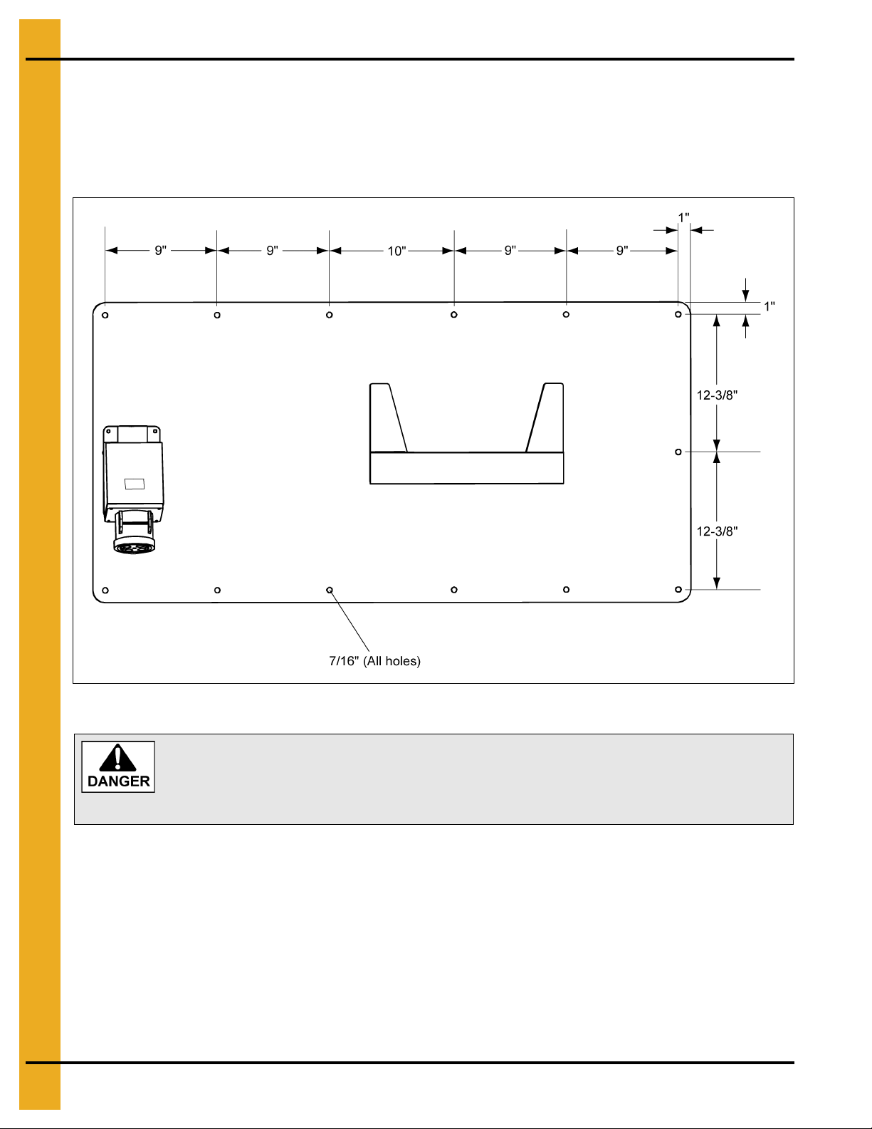
Docking Station Mount
Securely mount the docking station outside of the bin near the bin door. Figure 5A shows the hole pattern
and diameter. The docking station must be close enough to the bin door to plug in the 10' long foo t switch
cord. The operator must be outside of the bin and be able to depress the foot switch while visually
monitoring the sweep through the bin door.
Figure 5A Docking Station
18 PNEG-1366 12" and 16" Series II Sweep Quick Disconnect Control Box Kit
Page 19

5. Assembly
Control Panel Conduit Hole (Pre-June 2010)
NOTE: The Series II Sweep has used different control boxes. The quick disconnect kit will fit either style
box. Hardware is provided to mount an older style box (with ears) to the mounting plate. The new
style box already has hardware installed in the rear of the box.
1. Cut a hole into the side panel of the control box in the location shown in Figure 5B. Hole to be sized
for 1-1/2" rigid conduit (approximately 1.900"). Make sure all metal chips/shavings are removed from
the inside of the box.
Figure 5B
PNEG-1366 12" and 16" Series II Sweep Quick Disconnect Control Box Kit 19
Page 20

5. Assembly
Electrical controls should be installed by a qualified electrician and must meet
standards set by the National Electrical Code and all local and state codes.
A main power disconnect switch capable of being locked only in the OFF position
should be used. The disconnect must be LOCKED in the OFF position before
unplugging either end of the power cord. This has been integrated into the control
panel after June 2010.
Control Panel Installation
1. Remove the lock nut from the conduit hub. The conduit hub is factory installed on the conduit
assembly attached to the back base assembly.
2. Carefully inset the conduit hub, with wires, into the hole drilled during Step 1 on Page 19.
3. Install the lock nut on the hub and tighten.
4. Mount the control box to the back plate with the supplied hardware.
5. Use the supplied grounding lug (E160-1137) to properly ground the control box assembly to
the outlet.
Control Panel Receptacle Mounting (Current Style Panel)
Control Panel and Receptacle Installation
Open the control panel and mount it to the lift base panel assembly with the supplied hardware. There
are three (3) mounting positions on the lift base panel assembly in which to mount the control panel.
(See Figure 5C.)
Figure 5C
20 PNEG-1366 12" and 16" Series II Sweep Quick Disconnect Control Box Kit
Page 21

5. Assembly
Based on where the outlet for the drop cord is installed on the panel, all three (3) mounting positions may
not be possible. (See Figure 5D.)
Figure 5D
A sample installation configuration is shown in Figure 5E for the auger drive power outlet, tractor drive
power outlet, overload for motor control outlet and the drop cord outlet. Figure 5E shows preliminary
dimensions for all the necessary holes that need to be cut into the panel. Actual sizes may vary.
Figure 5E
PNEG-1366 12" and 16" Series II Sweep Quick Disconnect Control Box Kit 21
Page 22

5. Assembly
Use 1/4"-14 x 1-1/4" screws for handles that attach to the base back plate at the
stiffener bar locations. Use 1/4"-14 x 1" screws for handles that attach at all other
locations. These handles are for guidance only. See Figure 1A on Page 5 for
lifting instructions.
Using the wrong size screws can cause the threads to strip or not give enough
support and serious injury or death can occur.
Install each receptacle to the panel with the supplied hardware. Consult the wiring schematic in the panel
enclosure for proper electrical connection locations.
Once the receptacles have been properly installed, the auxiliary guidance handles can be attached to the
panel assembly.
Guidance Handle Installation
Attach handles. Four (4) handles are supplied and can be located in any of the holes on the outside
edges of the back base plate. USE THE CORRECT SIZE SCREWS. (Only two (2) handles shown.)
(See Figure 5F below and Figure 5G on Page 23.)
22 PNEG-1366 12" and 16" Series II Sweep Quick Disconnect Control Box Kit
Figure 5F
Page 23

5. Assembly
Figure 5G
PNEG-1366 12" and 16" Series II Sweep Quick Disconnect Control Box Kit 23
Page 24

5. Assembly
Do not lift equipment without personal or mechanical assistance. Single person lift
could cause injury.
To avoid muscle strain or back injury, use lifting aids and proper lifting techniques
when removing or replacing the control box.
Place Control Panel Into Docking Station
Attach the control box to the docking station by sliding the tongue into the pocket on the docking station.
(See Figure 5H.)
24 PNEG-1366 12" and 16" Series II Sweep Quick Disconnect Control Box Kit
Figure 5H
Page 25

5. Assembly
Control Panel Setup
NOTE: The control panel may have to be reprogrammed for peak performance after being moved to a
different bin.
The bin must have grain in it to be able to properly fine tune the control panel.
If the meter looks like this:
Figure 5I
Control Panel Calibration
Observe the tractor drive motor nameplate and the auger drive motor nameplate.
Record the full load amp (FLA) value for the specific voltage on each motor.
Auger drive motor full load amps: ____
Tractor drive motor full load amps: ____
Switch the disconnect switch on the panel to OFF (not ON).
Unlock and open the control panel.
Adjust the FLA dial screw on the tractor drive motor contactor (M1) and the auger drive motor
contactor (M2) so that the indicator arrowhead is set slightly higher than the full load amp value listed
on the nameplates.
Tractor drive motor contactor (M1) FLA adjustment dial: ____
Auger drive motor (M2) FLA adjustment dial value: ____
Close and lock the control panel.
Switch the disconnect switch on the panel to ON (not OFF).
PNEG-1366 12" and 16" Series II Sweep Quick Disconnect Control Box Kit 25
Page 26

5. Assembly
Initial Display Setup
NOTE: If no keys are activated for 2 minutes, the display returns to the default state without saving any
configuration changes. At each value, after 5 seconds of inactivity, a description of the current
state will scroll across the display.
NOTE: Pressing and hold OK will re turn to the previous menu or return to t he default state without saving
the changed values or parameters.
Press OK on the display unit.
(IN) should be displayed on the unit.
Press or on the display unit until (CURR) is shown (not VOLT, POTM, or TEMP).
Press OK.
(RANG) should be displayed on the unit.
Press or on the display unit until 4-20 is shown (not 0-20).
Press OK.
(DEC.P) should be displayed on the unit.
Press or on the display unit until 11.11 is shown (not 1111, 111.1, 1.111 or .1111).
Press OK.
(DI.LO) should be displayed on the unit.
Press or on the display unit until 0 is shown.
Press OK.
(DI.HI) should be displayed on the unit.
The DI.HI value is 2x the value that the FLA dial on the auger drive motor (M2) that was set earlier.
2x FLA Dial: ____
Press or on the display unit until the correct value is shown.
Press OK repeatedly until “-----” is displayed. This indicates the programming described above has
been saved.
Make sure no individual is inside the bin.
Make sure the sweep will not contact any obstruction and cause damage.
Have an employee observe the sweep from outside the bin, through the open door.
The person observing the sweep is meant to have control over the safety foot switch.
Have another employee operate the control panel.
Switch the Run Mode switch so that Manual is selected (not Auto).
26 PNEG-1366 12" and 16" Series II Sweep Quick Disconnect Control Box Kit
Page 27

5. Assembly
Switch the Manual Mode switch to idle (not reverse or forward).
Depress the pedal in the safety foot switch.
Press the Start button on the control panel.
NOTE: If any damage is observed or there is abnormal operation of the sweep, shut it down immediately.
There are three (3) ways to accomplish this. 1) Remove the pressure on the safety foot switch.
2) Press the Stop button on the control panel. 3) Press in on the Enable/Disable button so that it
collapses appropriately. Switch the disconnect switch on the panel to OFF (not ON). Lock out the
panel before entering the bin to service the sweep.
Observe the no load amps (NLA) displayed on the meter on the front of the panel.
Auger drive motor no load amps: ____
The tractor motor operation (forward and stop) in automatic is dictated by the amp reading on the auger
drive motor.
The tractor drive motor is meant to shut off (idle) when the Auger Drive Motor reaches 90% of the
nameplate FLA.
90% of full load amps: ____
The tractor motor is meant to reactivate (forward) when the auger drive motor reaches 110% of the no load
amps (amperage observed when the auger flight turns freely in absence of grain).
110% of no load amps: ____
Final Display Setup
NOTE: If no keys are activated for 2 minutes, the display returns to the default state without saving any
configuration changes. At each value, after 5 seconds of inactivity, a description of the current
state will scroll across the display.
Press OK repeatedly until RELU is displayed on the unit.
Press or on the display unit until DISP is shown (not PERC).
Press OK.
REL1 should be displayed on the unit.
Press or on the display unit until SET is shown (not SKIP, or OFF).
Press OK.
SETP should be displayed on the unit.
Press or on the display unit the 90% of FLA value is shown.
Press OK.
ACT1 should be displayed on the unit.
Press or on the display unit until INCR is shown (not DECR).
Press OK.
PNEG-1366 12" and 16" Series II Sweep Quick Disconnect Control Box Kit 27
Page 28

5. Assembly
HYS1 should be displayed on the unit.
For this control panel hysteresis (HYS1) is measured as the different between 90% of full load amps and
110% of no load amps.
90% of full load amps: ____ minus 110% of no load amps: ____
Press or on the display unit until the correct value is shown.
Press OK.
ERR1 should be displayed on the unit.
Press or on the display unit until DEAC is shown (not HOLD, ACTI, or NONE).
Press OK.
ON.DE should be displayed on the unit.
Press or on the display unit until 0 is shown.
Press OK.
OF.DE should be displayed on the unit.
Press or on the display unit until 20 is shown.
Press OK.
REL2 should be displayed on the unit.
Press or on the display unit until OFF is shown (not SET or SKIP).
Press OK.
E.PAS should be displayed on the unit.
Press or on the display unit until NO is shown.
Press OK.
This function will allow the values that were entered to be locked.
NOTE: Using a password will stop access to the menu and parameters. There are two (2) levels of
password protection. Passwords between 0000 and 4999 allow access to the fast set point
adjustment and relay test. (Using this password stops access to all other parts of the menu.)
Passwords between 5000 and 9999 stop access to all parts of the menu, fast set point adjustment
and relay test. (Current set point is still shown.) By using the master password 2008, all
configuration menus are available.
28 PNEG-1366 12" and 16" Series II Sweep Quick Disconnect Control Box Kit
Page 29

5. Assembly
NEVER program the “High Amp Set Point” greater than the full load running
Amps of the auger motor.
If you select NO, press OK.
If you select YES, N.PAS will be displayed. Press or on the display unit until your password is shown.
Press OK. Document this password.
The password will be necessary if there needs to be changes to many of the configuration values.
If the meter looks like this:
Figure 5J
Follow these instructions:
NOTE: In order to fine tune the control panel, the bin must have grain in it.
The Series II Sweep is supplied with adjustable overloads that are not set at the factory. These should be
set slightly higher than the Full Load Amp (FLA) value listed on the motor nameplates.
A. Find the desired “High” Amp and “Low” Amp set points.
1. High Amp Set Point: The Amp load the auger draws when the auger flighting is 90% loaded.
This will turn OFF the tractor drive motor. Initially, set the value to 90% of the Full Load Amps
(FLA) listed on the motor nameplate.
2. Low Amp Set Point: The Amp load the auger motor draws when the auger flighting is 10%
loaded. This will turn ON the drive motor. Initially, set this value to 10% over the Amp draw of the
sweep running empty.
B. Programming the Amp Meter.
PNEG-1366 12" and 16" Series II Sweep Quick Disconnect Control Box Kit 29
Page 30

5. Assembly
Calibration
1.Setting Input
a. Press “PRGM” to “inPut”.
b. Press “ENTER”.
c. Press “PRGM” to “i4-20”.
d. Press “ENTER” to RUN MODE.
2. Setting Setup
a. Press “PRGM” to “SEtuP”.
b. Press “ENTER” to “rdEC”
Use arrow buttons to change the decimal placement. Show .0 Amps.
c. Press “ENTER” to “SETLO”.
d. Press “ENTER”
Value = 0.0
e. Press “ENTER” to “SEtHi”.
f. Press “Enter”
Value = 50.0
Use arrow buttons to change value.
g. Press “ENTER” to “LoCut”.
Press “ENTER”
This value = 0
h. Press “ENTER” to RUN MODE.
30 PNEG-1366 12" and 16" Series II Sweep Quick Disconnect Control Box Kit
Page 31

Operation
1. Setting Presets
a. Press “Pre A”.
b. Press “PRGM”
This value = “High Amp Set Point”.
Use arrow buttons to change value.
c. Press “ENTER”.
2. Setting Relays
a. Press “PRGM” to “rELAYS”.
b. Press “ENTER” to “HYS A”.
c. Press “PRGM”
This value = “High Amp Set Point”-“Low Amp Set Point”
Use arrow buttons to change value.
5. Assembly
d. Press “ENTER” to RUN MODE.
EXAMPLE: Full Load Running Amps = 21 Amps
High Amp Set Point = 20 Amps
Low Amp Set Point = 12 Amps
Then “HYS A” = 8 Amps
And “Pre A” = 20 Amps
NOTE: This is the difference between the High Amp Set Point and the Low Amp Set Point.
[20 Amps-12 Amps = 8 Amps]. Low amp set point is only used to calculate this value.
3. Locking the Amp Meter
1. Locking the Amp meter is not required but prevents the meter from being tampered with once it
is programmed.
2. In RUN MODE, press “LOCK” three (3) times within five (5) seconds.
This value = A number that is easily remembered.
Use arrow buttons to change value.
a. Press “ENTER”.
4. Unlocking the Amp Meter
1. In RUN MODE, press “LOCK” three (3) times within five (5) seconds.
a. Enter the “LoC” value.
Use arrow buttons to change value.
b. Press “ENTER”.
NOTE: It is recommended to write down the “LoC” value and keep it in a safe place in case it
is forgotten.
PNEG-1366 12" and 16" Series II Sweep Quick Disconnect Control Box Kit 31
Page 32

6. Start-Up
To ensure that the drive is not unexpectedly started, turn OFF and lock out the
power source before proceeding. Failure to observe these precautions could
result in bodily injury.
Failure to perform any or all of these pre-start checks may cause damage to the
equipment and/or cause SERIOUS INJURY or DEATH to those in the work area.
Failure to perform any or all of these pre-start checks may also be a misuse of
the equipment. Any misuse of the equipment may void the warranty.
ALWAYS keep ALL guards and shields in place, until all the power is
disconnected and locked out.
Be sure to remove the grain from the drive chain and sprockets. If this is not
done, damage can occur to the drive system.
Make certain ONLY trained operators are in the work area before operating or
moving the machine. Two (2) people must always be in position to monitor the
operation of the equipment from outside the bin.
Perform Pre-Start Checks
1. Make sure ALL shields are in place.
2. Inspect the drive unit for any problems or potential problems.
3. Be aware of any emergency shut down procedures. Two (2) people must always be in position to
monitor the operation of the equipment from outside the bin.
4. Before starting the auger for the first time, make sure that all parts are assembled correctly according
to the instructions in this manual.
32 PNEG-1366 12" and 16" Series II Sweep Quick Disconnect Control Box Kit
Page 33

6. Start-Up
DO NOT start or stop the auger while it is under load.
Failures may occur if the auger is run full before it has been “polished” during
the “break-in” period.
NEVER operate the auger empty. Operating augers empty for any length of
time will cause excessive wear. NEVER operate the auger at speeds higher
than recommended.
Be aware of any unusual vibration or noises during the initial start-up and
“break-in” period. If anything unusual is detected, immediately shut down the
auger and disconnect and lock out the power supply before servicing.
Start the Auger
1. Plug the two (2) motors, foot switch and thermal protection cords into the bottom of the control panel
while making sure they are locked into the receptacles. Each plug is different and can only be
plugged into one receptacle to prevent accidental electric shock and/or overloads.
2. Step on the foot switch and press the “Start” button.
3. Run the auger through a “break-in” period if it is being used for the first time or for the first time of
the season.
4. “Polish” the flighting by running the auger at partial capacity until it is smooth, before attempting
full capacity.
PNEG-1366 12" and 16" Series II Sweep Quick Disconnect Control Box Kit 33
Page 34

7. Operation
Gear reducer is shipped without oil. Add the proper amount of the recommended
lubricant before operating. Failure to observe these precautions could result in
damage to, or destruction of, the equipment.
Keep out of the bin while the bin sweep auger is in operation. The rapidly moving
sweep auger can cause SERIOUS INJURY or DEATH.
Be alert for any unusual vibrations, noises and the loosening of any fasteners. If
anything unusual is detected, immediately shut down the auger, disconnect and
lock out the power source before servicing.
NEVER enter the bin while the bin sweep is in operation.
NEVER attempt to control the operation of the bin sweep by depressing the
operating controls with shovels, brooms or any other objects.
DO NOT attempt to restrain movement of the bin sweep with ropes, bars or
other devices.
NEVER allow an operator to attempt to manually restrain the bin sweep.
Operating the Sweep Auger
NOTE: The auger capacity can fluctuate greatly under varying conditions. Moisture content, different
commodities, amount of foreign matter and speeds all play a part in the performance of the
auger. Twenty five percent (25%) moisture may cut capacity by as much as 40% under
some conditions.
1. Make certain there are at least two (2) people in the work area to monitor operations at all times.
2. Start the bin unloading equipment before starting the bin sweep auger.
3. Shut down the auger as soon as the bin is empty.
4. Consideration should be given to the proper size auger for any intermittent type operations. When
augers are stopped and restarted under full load, it may result in damage to the auger. Using a
larger diameter auger and reducing its load level will be far better than subjecting a smaller diameter
auger to big loads. If an auger is kept from absolute filling, it will make start-up easier and will convey
more efficiently.
34 PNEG-1366 12" and 16" Series II Sweep Quick Disconnect Control Box Kit
Page 35

7. Operation
Operating the Sweep Auger Control Panel
A. The sweep operates in two (2) different “modes”.
1. Automatic (The auger motor runs and the drive motor runs using the Amp Meter in the
control panel.)
Step on the foot switch and press the “Start” button. The auger motor will turn ON and the drive
motor will turn ON only if the Amp Meter reaches the “Low” set point.
2. Manual (Overrides the Amp Meter and allows the operator to manually move the sweep.)
a. Idle (Allows the auger motor to run, but does not move the sweep forward or reverse.)
b. Forward (Auger motor will run and moves the sweep towards the grain.)
c. Reverse (Stops the auger motor and moves the sweep away from the grain.)
Step on the foot switch and press the “Start” button. The auger motor will turn, but the sweep will not move.
Turn the “Manual” switch to “Forward” and the sweep will move forward towards the grain. Turn the
“Manual” switch to “Reverse” and the auger motor will shut off and move the sweep b ackwards away from
the grain.
The “Start” button MUST be pressed to start the auger motor again.
NOTE: The foot switch MUST be depressed and the thermal protection must be connected before the
sweep will operate.
PNEG-1366 12" and 16" Series II Sweep Quick Disconnect Control Box Kit 35
Page 36

8. Shut Down
NEVER start the equipment under load. Doing so may cause damage. This type of
damage is considered a misuse of the equipment. Any misuse of the equipment
may void the warranty.
Normal Shut Down
1. Before shutting down the unit, be sure the sumps and unload conveyor are empty.
2. Press the “Stop” button on the control panel.
Emergency Shut Down
1. Know how to shut down the auger in case of an emergency.
2. Step off the foot switch and press the “Stop” button.
3. Disconnect and lock out the power source.
Storage Preparation
1. Be sure the sumps and unload conveyor are empty.
2. Close the sump control gates.
3. Park the sweep behind the intermediate sumps, so that the sumps are on the auger side of
the sweep.
4. Shut down the auger.
5. Make sure all fasteners are tight.
6. After allowing the motors to cool down, cover the motors with the tarps supplied with the sweep.
7. Place blocks under the frame of the sweep to help support the sweep during storage.
36 PNEG-1366 12" and 16" Series II Sweep Quick Disconnect Control Box Kit
Page 37

9. Maintenance
ALWAYS shut down and disconnect the power supply before adjusting,
servicing or cleaning the equipment.
ALL SPEED REDUCERS ARE SHIPPED DRY. OIL MUST BE ADDED PRIOR TO
OPERATION. Do not operate the unit without making sure it contains the correct
amount of oil. Do not overfill or underfill with oil or injury to personnel, unit or other
equipment may result.
Do not mix non-synthetic and synthetic oil in the unit.
Maintain the Auger
A. Use caution when repairing or replacing equipment parts.
B. Make sure ALL decals are legible and securely attached to the auger. If necessary, replace them
FREE OF CHARGE by contacting GSI at:
GSI
P.O. Box 20
1004 E. Illinois St.
Assumption, IL 62510
Phone: 1-217-226-4421
C. Ensure that ALL electric motors, etc. are operating at the proper speed.
D. Make sure ALL electrical wiring is not damaged and that it meets proper wiring codes.
E. Make sure ALL components are in good working condition before use.
PNEG-1366 12" and 16" Series II Sweep Quick Disconnect Control Box Kit 37
Page 38

10. Control Panel Diagrams
Series II Sweep Control Package - 08-32A:3-12A, Non-575V (S2PFA)
Series II Sweep Control Package - 08-32A:3-12A, Non-575V (S2PFA)
Auger Drive Motor Amps Tractor Drive Motor Amps Voltage Auger Drive HP Tractor Drive HP
208 2 - 7-1/2 3/4-3
230 3-10 2-3
8-32 3-12
380 5-15 2-5
415 5-20 3 - 7-1/2
460 7-1/2 - 20 1-1/2 - 7-1/2
38 PNEG-1366 12" and 16" Series II Sweep Quick Disconnect Control Box Kit
Page 39

10. Control Panel Diagrams
Series II Sweep Control Package - 30-40A:3-12A, Non-575V (S2PFB)
Series II Sweep Control Package - 30-40A:3-12A, Non-575V (S2PFB)
Auger Drive Motor Amps Tractor Drive Motor Amps Voltage Auger Drive HP Tractor Drive HP
208 10 3/4-3
230 15 2-3
30-40 3-12
380 20 2-5
415 20-25 3 - 7-1/2
460 25-30 1-1/2 - 7-1/2
PNEG-1366 12" and 16" Series II Sweep Quick Disconnect Control Box Kit 39
Page 40

10. Control Panel Diagrams
Series II Sweep Control Package - 08-32A:3-12A, 575V Only (S2PFC)
Series II Sweep Control Package - 08-32A:3-12A, 575V Only (S2PFC)
Auger Drive Motor Amps Tractor Drive Motor Amps Voltage Auger Drive HP Tractor Drive HP
8-32 3-12 575 7-1/2 - 30 2-10
40 PNEG-1366 12" and 16" Series II Sweep Quick Disconnect Control Box Kit
Page 41

10. Control Panel Diagrams
Control Panel Schematic (460/3/60) Pre-June 2010
PNEG-1366 12" and 16" Series II Sweep Quick Disconnect Control Box Kit 41
Page 42

10. Control Panel Diagrams
Control Panel Schematic (230/3/60) Pre-June 2010
42 PNEG-1366 12" and 16" Series II Sweep Quick Disconnect Control Box Kit
Page 43

10. Control Panel Diagrams
Control Panel Schematic (380/3/50) Pre-June 2010
PNEG-1366 12" and 16" Series II Sweep Quick Disconnect Control Box Kit 43
Page 44

11. Troubleshooting
Problem Possible Cause Solution
1. Power cords may be unplugged. 1. Plug in the power cords.
1. Sweep does not run.
2. Low capacity.
3. Sweep does not move
around the bin.
4. The sweep is vibrating.
2. Foot switch may not be actuated.
3. Overloads may be tripped. 3. Reset the overloads.
4. Adjustable overloads not set correctly.
1. The auger may not be fully loaded.
2. The auger is moving too slowly.
1. The control panel may not be in
“Automatic Mode”.
2. The amp meter is not properly adjusted.
3. The drive chain may be broken. 3. Repair the drive chain.
1. The auger may have foreign materials
in it.
2. The hanger bearings may be worn. 2. Replace the hanger bearings.
3. The flight connections may be loose. 3. Tighten all of the flight connecting bolts.
2. Make sure the foot switch is depressed and
the switch is operating properly.
4. Set overload to value listed on motor
nameplate for full load amps.
1. Make sure the grain is flowing into the
auger, making it fully loaded.
2. Check the auger speed. Low capacity
will result from speeds slower
than recommended.
1. Turn the switch to “Automatic Mode”.
2. Set the amp meter so the running
amps of the auger motor will turn ON
the drive motor.
1. Remove the foreign material.
4. The flighting may be worn.
4. Replace all the flighting sections that
are worn.
44 PNEG-1366 12" and 16" Series II Sweep Quick Disconnect Control Box Kit
Page 45

12. Parts List
1. Control Panel Components Pre-June 2010 Style Panel
2. Quick Detach Control Panel Assembly (GC10115) Pre-June 2010
3. Control Box Base Assembly (GC10109) (for Quick Detach Control Panel) Pre-June 2010
4. Dock Station Assembly (GC10116) (for Quick Detach Control Panel) Pre-June 2010
5. Conduit Assembly (GC10113) (for Quick Detach Control Panel)
6. Drop Cord Assembly (GC10079) (for Quick Detach Control Panel) Pre-June 2010
7. Quick Detach Control Panel Receptacles Parts
8. Quick Detach Control Panel Package (GK80112)
9. Lift Base Panel Assembly (GK80108)
10. Lift Base Dock Assembly (GK80110)
11. Drop Cord Assembly (GK80111)
PNEG-1366 12" and 16" Series II Sweep Quick Disconnect Control Box Kit 45
Page 46

12. Parts List
Control Panel Components Pre-June 2010 Style Panel
46 PNEG-1366 12" and 16" Series II Sweep Quick Disconnect Control Box Kit
Page 47

12. Parts List
Control Panel Components Pre-June 2010 Style Panel Parts List
Ref # Part # Description
1 DC-1224 Decal, Danger, High Voltage
2 DC-1536 Decal, Series II Sweep Panel Overlay
3 DC-889 Decal, Danger, High Voltage
4 GC03659 Switch, Standard - Round - Push Button - Plastic - Flush - Red GE (#P9XPNRG)
5 GC03666 Receptacle, 3P4W, 50A, 3 PH, 480V - CS8169
6 GC03667 Cover, 50A Receptacles, FS/FD Mount, 1 Gang - HBL7774WO
N/S GC03668 Plug, 3P4W, 50A, 3 PH, 480V - CS8165C
7 GC03669 Receptacle, 3P4W, 20A, 3 PH, 480V, L16-20R - HBL2430SW
N/S GC03670 Plug, 3P4W, 20A, 3 PH, 480V, L16-20P - HBL2431SW
8 GC06954 Receptacle, 2P3W, 20A, 277V, L7-20R - HBL2330SW
9 GC06956 Blank, 2 Position - Maint - Plastic GE (#P9XSMD0N)
10 GC06957 Switch, 3 Position Lever SL Momentary GE (#P9XSVU3N)
11 GC06958 Switch, Standard - Round - Push Button - Plastic - Flush - Green GE (#P9XPNVG)
12 GC06959 Contact, Block/1 N.O./SCR
13 GC06960 Contact, Block/1 N.C./SCR
14 GC06961 Contact, Block/SCR
15 GC07585 Panel, Series II Sweep Amp Meter Device
16 GC03671 Receptacle, 2P3W, 20A, 125V, L5-20R - HBL2310SW
N/S GC03672 Plug, 2P3W, 20A, 125V, L5-20P - HBL2311SW
N/S GC06857 Series II Sweep Safety Foot Switch Assembly
PNEG-1366 12" and 16" Series II Sweep Quick Disconnect Control Box Kit 47
Page 48

12. Parts List
Quick Detach Control Panel Assembly (GC10115) Pre-June 2010
Quick Detach Control Panel Assembly (GC10115) Pre-June 2010 Parts List
Ref # Part # Description Qty
1 GC10109 Control Box Base 1
2 GC10116 Dock Station Assembly 1
3 GC10079 Drop Cord 1
48 PNEG-1366 12" and 16" Series II Sweep Quick Disconnect Control Box Kit
Page 49

12. Parts List
Control Box Base Assembly (GC10109) (for Quick Detach Control
Panel) Pre-June 2010
Control Box Base Assembly (GC10109) Parts List
Ref # Part # Description Qty
1 GC10107 Base Back Plate Weldment 1
2 GC10071 Box, S2S2 Electrical Back BB602W 60A with 1-1/2" Hub Hubell 1
3 GC10073 Inlet 1
4 S-6998 Bolt, HHCS 1/4"-20 x 1" ZN Grade 5 3
5 S-2041 Split Lock Washer 1/4" ZN 3
6 S-1120 Hex Nut 1/4"-20 ZN Grade 5 3
7 GC10113 Conduit Assembly 1
8 F-7050 Plastic Handle 2
9 S-9315 Screw, SMSAB 1/4" x 1-1/4" HWHS ZN 4
10 S-8166 Screw, SMSAB 1/4" x 1" HWH ZN 4
11 DC-1756 Decal, Warning, Lifting Hazard 2
N/S GC10224 Wire, 6 Gauge x 3' Stranded - Black 3
N/S GC10225 Wire, 6 Gauge x 3' Stranded THHN - Green 1
N/S E160-1137 Electrical Grounding Lug #TA-2 (CSA) 1
PNEG-1366 12" and 16" Series II Sweep Quick Disconnect Control Box Kit 49
Page 50

12. Parts List
Dock Station Assembly (GC10116) (for Quick Detach Control
Panel) Pre-June 2010
Dock Station Assembly (GC10116) Parts List
Ref # Part # Description Qty
1 GC10103 S2S2 Fixed Base Weldment - Kid Control Box 1
2 GC10071 Box, S2S2 Electrical Back BB602W 60A with 1-1/2" Hub Hubell 1
3 GC10072 Receptacle 1
4 S-6998 Bolt, HHCS 1/4"-20 x 1" ZN Grade 5 3
5 S-2041 Split Lock Washer 1/4" ZN 3
6 S-1120 Hex Nut 1/4"-20 ZN Grade 5 3
50 PNEG-1366 12" and 16" Series II Sweep Quick Disconnect Control Box Kit
Page 51

12. Parts List
Conduit Assembly (GC10113) (for Quick Detach Control Panel)
Conduit Assembly (GC10113) Parts List
Ref # Part # Description Qty
1 GC10111 Elbow, 1-1/2" Conduit 1
2 GC10110 Hub, 1-1/2" Conduit 1
3 GC10112 Nipple, 1-1/2" Conduit 2
PNEG-1366 12" and 16" Series II Sweep Quick Disconnect Control Box Kit 51
Page 52

12. Parts List
Drop Cord Assembly (GC10079) (for Quick Detach Control Panel)
Pre-June 2010
Drop Cord Assembly (GC10079) Parts List
Ref # Part # Description Qty
1 GC10078 S2S2 Electrical Cable for Drop Cord 1
2 GC10074 Plug, Male 1
3 GC10075 Plug, Female 1
52 PNEG-1366 12" and 16" Series II Sweep Quick Disconnect Control Box Kit
Page 53

Quick Detach Control Panel Receptacles Parts
12. Parts List
Quick Detach Control Panel Receptacles Parts List
Ref # Part # Description
1 GC11769 Receptacle, Female, 3P4W, 60A, 3 PH, 600V - HBL460R5W
2 S2PFA Series II Sweep Control Package - 08-32A:3-12A, Non-575V
2 S2PFB Series II Sweep Control Package - 30-40A:3-12A, Non-575V
2 S2PFC Series II Sweep Control Package - 08-32A:3-12A, 575V Only
3 GC03666 Receptacle, 3P4W, 50A, 3 PH, 480V - CS8169
4 GC03667 Cover , 50A Receptacles, FS/FD Mount, 1 Gang - HBL7774WO
5 GC03669 Receptacle, 3P4W, 20A, 3 PH, 480V, L16-20R - HBL2430SW
6 GC06954 Receptacle, 2P3W, 20A, 277V, L7-20R - HBL2330SW
PNEG-1366 12" and 16" Series II Sweep Quick Disconnect Control Box Kit 53
Page 54

12. Parts List
Quick Detach Control Panel Package (GK80112)
Quick Detach Control Panel Package (GK80112) Parts List
Ref # Part # Description
1 GK80110 Lift Base Dock Assembly
2 GK80108 Lift Base Panel Assembly
3 GK80111 Drop Cord Assembly
54 PNEG-1366 12" and 16" Series II Sweep Quick Disconnect Control Box Kit
Page 55

Lift Base Panel Assembly (GK80108)
12. Parts List
Lift Base Panel Assembly (GK80108) Parts List
Ref # Part # Description
1 GK80106 Lift Base Panel Welded Assembly
2 F-7050 Plastic Handle
3 S-9315 Screw, SMSAB 1/4" x 1-1/4" HWHS ZN
4 DC-1756 Decal, Warning, Lifting Hazard
5 GC11769 Receptacle, Female, 3P4W, 60A, 3 PH, 600V - HBL460R5W
6 S-8166 Screw, SMSAB 1/4" x 1" HWH ZN
7 S-7447 5/16"-18 x 1" Serrated Flange Bolt Stainless Steel
8 S-8452 5/16"-18 Serrated Flange Nut Waxed Stainless Steel
N/S GC10224 Wire, 6 Gauge x 3' Stranded - Black
N/S GC10225 Wire, 6 Gauge x 3' Stranded THHN - Green
PNEG-1366 12" and 16" Series II Sweep Quick Disconnect Control Box Kit 55
Page 56

12. Parts List
Lift Base Dock Assembly (GK80110)
Lift Base Dock Assembly (GK80110) Parts List
Ref # Part # Description
1 GC10103 S2S2 Fixed Base Weldment - Kid Control Box
2 GC10071 Box, S2S2 Electrical Back BB602W 60A with 1-1/2" Hub Hubell
3 GC11769 Receptacle, Female, 3P4W, 60A, 3 PH, 600V - HBL460R5W
4 DC-889 Decal, Danger, High Voltage
5 S-6998 Bolt, HHCS 1/4"-20 x 1" ZN Grade 5
6 S-2041 Split Lock Washer 1/4" ZN
7 S-1120 Hex Nut 1/4"-20 ZN Grade 5
56 PNEG-1366 12" and 16" Series II Sweep Quick Disconnect Control Box Kit
Page 57

Drop Cord Assembly (GK80111)
12. Parts List
Drop Cord Assembly (GK80111) Parts List
Ref # Part # Description
1 GC10078 S2S2 Electrical Cable for Drop Cord
2 GC11770 Plug, Male, 3PW4, 60A, 3 PH, 600V - HBL460P5W
PNEG-1366 12" and 16" Series II Sweep Quick Disconnect Control Box Kit 57
Page 58

NOTES
58 PNEG-1366 12" and 16" Series II Sweep Quick Disconnect Control Box Kit
Page 59
13. Warranty
9101239_1_CR_rev7.DOC (revised July 2009)
GSI Group, LLC Limited Warranty
The GSI Group, LLC (“GSI”) warrants products which it manufactures to be free of defects in materials and workmanship
under normal usage and conditions for a period of 12 months after sale to the original end-user or if a foreign sale,
14 months from arrival at port of discharge, whichever is earlier. The end-user’s sole remedy (and GSI’s only obligation)
is to repair or replace, at GSI’s option and expense, products that in GSI’s judgment, contain a material defect in materials
or workmanship. Expenses incurred by or on behalf of the end-user without prior written authorization from the GSI
Warranty Group shall be the sole responsibility of the end-user.
Warranty Extensions:
The Limited Warranty period is extended for the following products:
Product Warranty Period
Performer Series Direct Drive Fan Motor 3 Years
AP Fans and Flooring
Cumberland
Feeding/Watering
Systems
Grain Systems Grain Bin Structural Design 5 Years
Grain Systems
Farm Fans
Zimmerman
All Fiberglass Housings Lifetime
All Fiberglass Propellers Lifetime
Feeder System Pan Assemblies 5 Years **
Feed Tubes (1-3/4" and 2.00") 10 Years *
Centerless Augers 10 Years *
Watering Nipples 10 Years *
Portable and Tower Dryers 2 Years
Portable and Tower Dryer Frames and
Internal Infrastructure †
5 Years
* Warranty prorated from list price:
0 to 3 years - no cost to end-user
3 to 5 years - end-user pays 25%
5 to 7 years - end-user pays 50%
7 to 10 years - end-user pays 75%
** Warranty prorated from list price:
0 to 3 years - no cost to end-user
3 to 5 years - end-user pays 50%
† Motors, burner components
and moving parts not included.
Portable dryer screens included.
Tower dryer screens not included.
GSI further warrants that the portable and tower dryer frame and basket, excluding all auger and auger drive components,
shall be free from defects in materials for a period of time beginning on the twelfth (12
and continuing until the sixtieth (60
th
) month from the date of purchase (extended warranty period). During the extended
th
) month from the date of purchase
warranty period, GSI will replace the frame or basket components that prove to be defective under normal conditions
of use without charge, excluding the labor, transportation, and/or shipping costs incurred in the performance of this
extended warranty.
Conditions and Limitations:
THERE ARE NO WARRANTIES THAT EXTEND BEYOND THE LIMITED WARRANTY DESCRIPTION SET FORTH
ABOVE. SPECIFICALLY, GSI MAKES NO FURTHER WARRANTY OF ANY KIND, EXPRESS OR IMPLIED,
INCLUDING, WITHOUT LIMITATION, WARRANTIES OF MERCHANTABILITY OR FITNESS FOR A PARTICULAR
PURPOSE OR USE IN CONNECTION WITH: (I) PRODUCT MANUFACTURED OR SOLD BY GSI OR (II) ANY ADVICE,
INSTRUCTION, RECOMMENDATION OR SUGGESTION PROVIDED BY AN AGENT, REPRESENTA TIVE OR
EMPLOYEE OF GSI REGARDING OR RELATED TO THE CONFIGURATION, INSTALLATION, LAYOUT, SUITABILITY
FOR A PARTICULAR PURPOSE, OR DESIGN OF SUCH PRODUCTS.
GSI shall not be liable for any direct, indirect, incidental or consequential damages, including, without limitation, loss of
anticipated profits or benefits. The sole and exclusive remedy is set forth in the Limited Warranty, which shall not exceed
the amount paid for the product purchased. This warranty is not transferable and applies only to the original end-user. GSI
shall have no obligation or responsibility for any representations or warranties made by or on behalf of any dealer, agent
or distributor.
GSI assumes no responsibility for claims resulting from construction defects or unauthorized modifications to products
which it manufactured. Modifications to products not specifically delineated in the manual accompanying the equipment at
initial sale will void the Limited Warranty.
This Limited Warranty shall not extend to products or parts which have been damaged by negligent use, misuse, alteration,
accident or which have been improperly/inadequately maintained. This Limited Warranty extends solely to products
manufactured by GSI.
Prior to installation, the end-user has the responsibility to comply with federal, state and local codes which apply to the
location and installation of products manufactured or sold by GSI.
PNEG-1366 12" and 16" Series II Sweep Quick Disconnect Control Box Kit 59
Page 60

This equipment shall be installed in accordance with
the current installation codes and applicable
regulations which should be carefully followed in all
cases. Authorities having jurisdiction should be
consulted before installations are made.
Copyright © 2010 by GSI Group
Printed in the USA
GSI Group
1004 E. Illinois St.
Assumption, IL 62510-0020
Phone: 1-217-226-4421
Fax: 1-217-226-4420
www.gsiag.com
 Loading...