

thermio™ eco C3
EN
Operating manual
This manual ensures safe and efficient use of the “thermio™ eco C3” thermostat (referred to as
“device” in the following). This manual is a component of the device and must remain accessible at all
times for everyone who uses the device.
Everyone who uses the device must have read and understood this manual before commencing any
work. The basic prerequisite for working safely is compliance with all safety instructions and usage
instructions specified in this manual. Furthermore, the local accident prevention regulations and the
general safety regulations in the area in which the device is operated apply.
Copyright
This manual is copyright protected.
Handover of this manual to third parties, reproductions of any type and form – including excerpts – and
use and/or disclosure of the content without the written permission of Grässlin GmbH (referred to as
“manufacturer” in the following), except for internal purposes, is not permitted. Violations will result in
liability for compensation. The manufacturer reserves the right to assert additional claims.
The copyright is held by the manufacturer.
2
© Grässlin GmbH
Bundesstr. 36
78112 St. Georgen
GERMANY
Declaration of conformity and download instructions
The declaration of conformity for the device described in this manual, and a download of this manual,
can be found at
www.graesslin.de
.
EN
3
Overview................................................................................................. 6
Design and function.............................................................................................................. 6
Contents............................................................................................................................. 15
Safety................................................................................................... 16
Installation............................................................................................ 21
On-wall mounting............................................................................................................... 22
Inserting the battery............................................................................................................ 31
Operation............................................................................................. 36
Prior to operation................................................................................................................ 36
Setting the frost protection temperature.............................................................................. 39
Setting the temperature setpoint......................................................................................... 40
Setting the date/time.......................................................................................................... 42
Programming periods.......................................................................................................... 43
Selecting the operating mode.............................................................................................. 46
4
Activating/deactivating the holiday function......................................................................... 47
Selecting the background lighting....................................................................................... 47
Replacing the battery.......................................................................... 49
Disposal................................................................................................ 55
Technical data...................................................................................... 57
123
%
456
α
789
λ
123
Ω
EN
5
Overview
Design and function
Design
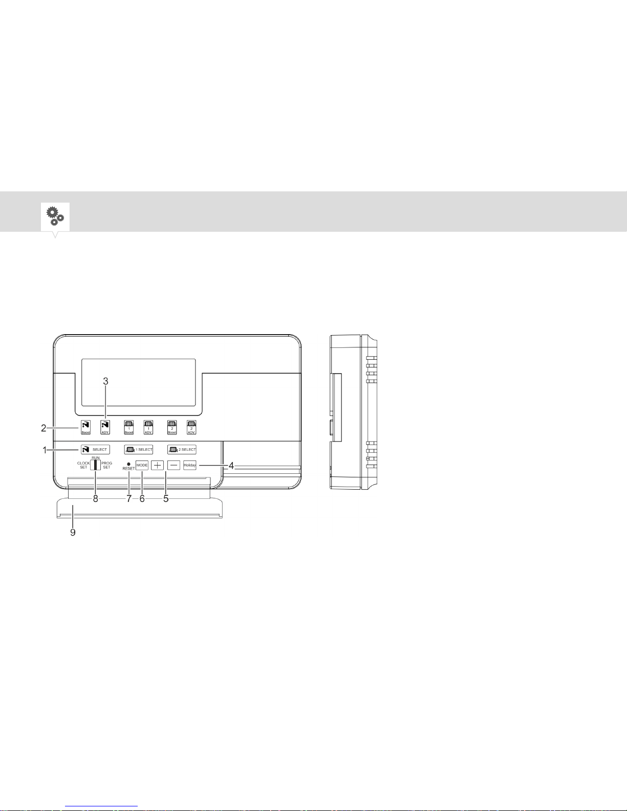
Fig. 1: Front and side view
6
1 SELECT button
2 Boost button
3 ADV. button
4 Holiday button
5 Plus/minus buttons
6 MODE button
7 RESET button
8 Selection switch for operation, time and
programming
9 Cover
The “thermio™ eco C3” thermostat is used to regulate three heating circuits. Hot water or heating circuits can be connected and regulated independently of each other. Individual regulation of, for example,
two independent heating zones (living and sleeping areas) and hot water is implemented using three
independent switching outputs.
In the standard method, the water or room temperature is regulated by switching the device on and off
for periods of time. The on and off times for these periods can be programmed individually. In addition,
you can set a setpoint for the room temperature if the temperature regulation function is activated. An
additional frost protection function protects the device or the connected pipelines against frost when the
device is switched off.
EN
7
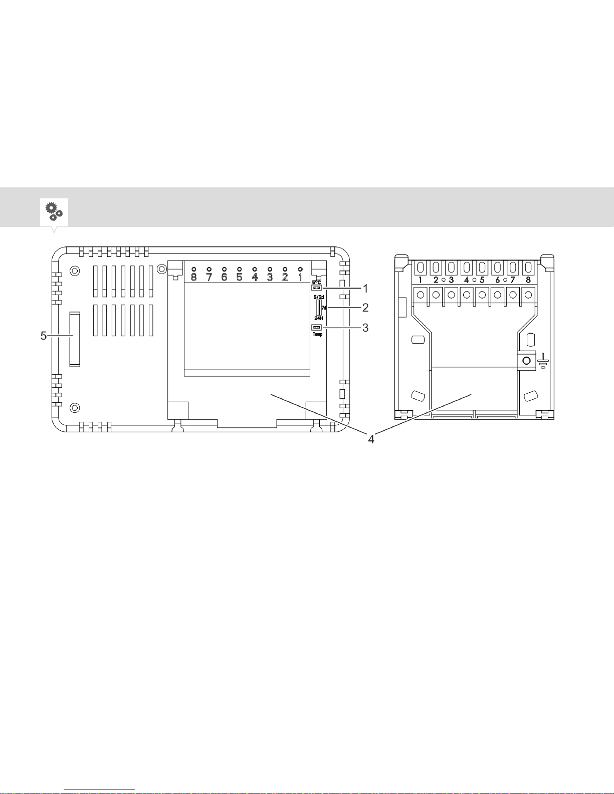
Fig. 2: Rear view (without mounting plate) and mounting plate
1 Frost protection function (jumper)
2 Programming mode
3 Temperature regulation function
(jumper)
4 Mounting plate
5 Battery compartment
8

Temperature regulation function (for heating systems only)
If the temperature regulation function (Fig. 2/3) is activated, the device measures the room temperature
and regulates to an individually adjustable temperature setpoint Ä Chapter "Prior to operation"
on page 36.
The temperature regulation function (Fig. 2/3) and the frost protection function (Fig. 2/1) are activated
and deactivated by means of what are known as jumpers. The jumpers are included in the contents. If
the jumper is inserted in an opening, the corresponding function is activated. If the jumper is removed
from the opening, the corresponding function is deactivated.
Programming mode
To keep the water and/or room temperature at a constant level, the system is switched on and off for
periods of time. You set the desired programming mode using the switch on the back of the device
(Fig. 2/2). You can program periods of different lengths and at different intervals for each day of the
week Ä Chapter "Programming periods" on page 43.
EN
9
24 h - Use the same programming for each day
7 d - Days are programmed independently of each other
5/2 d - Use two programs, one for weekdays (Monday to Friday) and one for the weekend (Saturday,
Sunday)
The following periods are pre-installed on delivery:
P1 On P1 Off P2 On P2 Off P3 On P3 Off
24 h 06:30 08:30 12:00 14:00 16:30 22:30
7 d 06:30 08:30 12:00 14:00 16:30 22:30
5/2 d (Mon –
Fri)
5/2 d (Sat –
Sun)
06:30 08:30 12:00 14:00 16:30 22:30
07:30 10:00 12:00 14:00 17:00 22:30
10
On delivery, the 7 d programming for all seven days of the week is used.
The active temperature regulation function takes the programmed periods into consideration, provided
that the temperature setpoint is maintained. If the room temperature deviates from the temperature setpoint, the temperature regulation function switches on and overrides the programmed periods once for
the deviation.
Period selection
The device has a total of five different operating modes: ON, 3, 2, 1 and OFF. You can switch between
the different operating modes by pressing the SELECT button (Fig. 1/1).
Info on display Function
ON 3 2 1 OFF The device is permanently on.
ON 3 2 1 OFF The device switches 3 periods each day.
EN
11

Info on display Function
ON 3 2 1 OFF The device switches 2 periods each day. P1 and
P3 are executed, P2 is ignored.
ON 3 2 1 OFF The device switches 1 period each day, from the
first on-period to the last off-period (P1 On – P3
Off).
ON 3 2 1 OFF The device is permanently off.
Boost function
The Boost button (Fig. 1/2) enables a short on-period lasting one to three hours. The programmed
periods are not affected.
• Boost during on-period: extends the active on-period by one to three hours
• Boost during off-period: activates a short on-period for one to three hours
12
Pressing the Boost button once extends/activates the period for one hour.
Additional function
The ADV. button (Fig. 1/3) inverts the active period. The programmed periods are not affected.
• ADV. during on-period: switches the active period off until the next programmed on-period
• ADV. during off-period: switches the active period on ahead of schedule until the next pro-
grammed off-period
Holiday function
The Holiday button (Fig. 1/4) activates the holiday function. The device is switched off for the holiday
period set by the user Ä Chapter "Activating/deactivating the holiday function" on page 47.
Frost protection function
The frost protection (Fig. 2/1) protects the heating system water pipes connected to the device against
freezing when the device is in an off-period or has been switched off manually.
EN
13
On delivery, the frost protection function is activated and set to a temperature of +10°C. The frost protection function can be deactivated on the rear of the device. The temperature of the frost protection
function can be set to between +5°C and +20°C Ä Chapter "Setting the frost protection temperature"
on page 39.
The frost protection function can only be set for heating systems. The device
only measures the temperature of the room in which it is installed.
Battery
In the event of a power failure, the battery provides the electricity to prevent loss of the stored date, time
and programming. When the power supply is switched back on, the stored data is retrieved and the
device continues to operate as normal.
If the device is operated on the battery for more than 30 days, the data have to be reprogrammed.
14
Contents
The following components are included in the contents:
Number Designation
1 Thermostat thermio™ eco C3
2 Screws (3.5 x 25 mm)
2 Screws (3.5 x 20 mm)
2 Wall-plugs (5 x 25 mm)
2 Jumpers
1 Lithium battery of type 3V CR2032
EN
15

Safety
Safety instructions
Safety instructions are indicated in this manual by symbols. The safety instructions are introduced by
signal words that express the extent of the danger.
WARNING!
This combination of symbol and signal word indicates a potentially dangerous
situation that may result in death or severe injuries if the situation is not
avoided.
NOTICE!
This combination of symbol and signal word indicates a potentially dangerous
situation that may result in material damage if the situation is not avoided.
16
ENVIRONMENT!
This combination of symbol and signal word indicates potential dangers for
the environment.
Tips and recommendations
This symbol highlights useful tips and recommendations, as well as information for efficient and fault-free operation.
Intended use
The thermostat may only be used for timer regulation (optionally for temperature regulation) of heating
systems and hot water circuits in a temperature range from +5°C to +35°C.
Areas of application
• Boiler
• Combination boiler
EN
17
• Domestic heating technology for heating and water heating
• Pump-controlled central heating systems
• Gravity heating systems
• The multi-channel capability enables compliance with Part L England, Part J Scotland and Part F
Northern Ireland of the building regulations for homes exceeding 150 m².
The intended use also includes compliance with all information specified in this manual.
Any use other than the intended use is considered incorrect use. The legal warranty is voided by any
interference with, or modifications to, the device.
WARNING!
Danger due to insufficient wire cross-section!
If wires with an insufficient cross-section are used, a short circuit or fire may
occur.
− Only use terminals with a cross-section between 1 mm² and 2.5 mm²
for flexible wires.
18
Residual risks
The device is state-of-the art and designed in accordance with current safety requirements. However,
residual risks remain that require caution when using the device. The residual risks, and the conduct
and measures they require, are listed in the following.
WARNING!
Danger to life due to electric shock!
Improper assembly and installation of the device may result in life-threatening electrical voltages.
− Have assembly and connection performed by a qualified electrician only.
EN
19
Personnel requirements
Qualified electrician
Professional training, knowledge and experience, and knowledge of the relevant standards and regulations allows the qualified electrician to perform work on electrical systems and to identify, and avoid,
potential dangers of their own accord.
A qualified electrician is specifically trained for the work environment in which they work, and are
familiar with the relevant standards and regulations.
User
The user is the person who uses and operates the device in compliance with proper use, without any
prior knowledge.
20
Installation
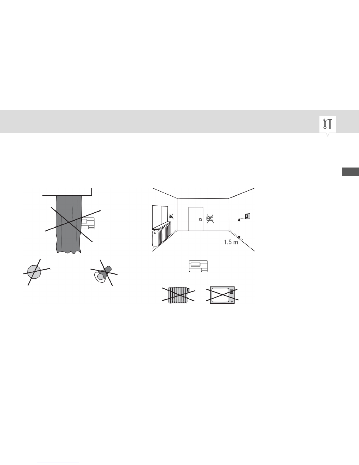
Installation location
In order to ensure fault-free measurement by the room thermostat, choose the right installation location.
Fig. 3: Installation location requirements
EN
21
 Loading...