

Page 1

YB500 OWNER’S MANUAL
HOW TO USE
YOUR GRUNDIG
YB500 AM/FM/SW Radio
NEED HELP? HERE’S HOW TO CONTACT US:
‧ From the United States: 1-800-872-2228
‧ From Canada: 1-800-637-1648
‧ From everywhere else: 650-903-3866
‧ e-mail: grundig@ix.netcom.com
‧ World Wide Web: www.grundigradio.com
‧ Eton Corporation/Grundig
1015 Corporation Way
Palo Alto, California 94303
United States
1
Page 2

Contents
Yacht Boy 500 - LC DATA MON I T O R (Displa y ) ............................................................................................................. 3
Your Unit at a Glance.......................................................................................................................................................... 4
Aerials................................................................................................................................................................................................... 6
Power Supply .............................................................................................................................................................................. 7
AC (Mains) Operation ........................................................................................................................................................... 7
Battery Operation................................................................................................................................................................... 7
Battery Check .......................................................................................................................................................................... 7
Data Protection........................................................................................................................................................................ 8
Reset Button............................................................................................................................................................................. 8
User Guide Via the Menu............................................................................................................................................................. 9
General Operation ......................................................................................................................................................................... 10
Key-protect............................................................................................................................................................................. 10
LOCKED.................................................................................................................................................................................... 10
Direct Entries ......................................................................................................................................................................... 10
Hints and Error Messages ................................................................................................................................................. 11
Display Illumination............................................................................................................................................................. 12
The Volume............................................................................................................................................................................. 12
The Tone.................................................................................................................................................................................. 12
Waveband Selection............................................................................................................................................................ 12
ROM Table of the Yacht Boy 500 ........................................................................................................................................ 13
Selecting Frequencies ......................................................................................................................................................... 13
Calling Up ROM Table Memory Locations ............................................................................................................................. 14
Step by Step into the World of Shortwave Reception ............................................................................................................. 15
Tuning to Stations with the TUNE A/V buttons.................................................................................................................. 16
Tuning to Stations......................................................................................................................................................................... 17
Entering a Meter Band ................................................................................................................................................................. 18
Storing in Memory Gen e r al ......................................................................................................................................................... 19
What can You Store?........................................................................................................................................................... 19
Is the Frequency Tuned to Already Stored in Memory?........................................................................................ 19
Checking the Desired Station Memory Position........................................................................................................ 20
Programming a Station Memory Location................................................................................................................... 20
Entering Abbreviations ....................................................................................................................................................... 21
Calling Up Stored Stations................................................................................................................................................ 21
The MEMORY Button ........................................................................................................................................................... 22
Clearing an Occupied Memory Position........................................................................................................................ 22
Going to Sleep to Radio .............................................................................................................................................................. 23
The Clock........................................................................................................................................................................................... 24
Setting the Clock .................................................................................................................................................................. 24
Setting the Clock .................................................................................................................................................................. 24
Clock Time Indication TIME I/II...................................................................................................................................... 24
Automatic Functions Timer ½ ..................................................................................................................................................... 25
Programming Switching Times Switching Times 1/2.............................................................................................. 25
Checking the Switching Times 1 /2............................................................................................................................... 26
Automatic Switching On and Off .................................................................................................................................... 26
Automatic Functions.................................................................................................................................................................... 27
Special Functions on FM ........................................................................................................................................................... 28
Special Functions on AM .......................................................................................................................................................... 29
2
Page 3
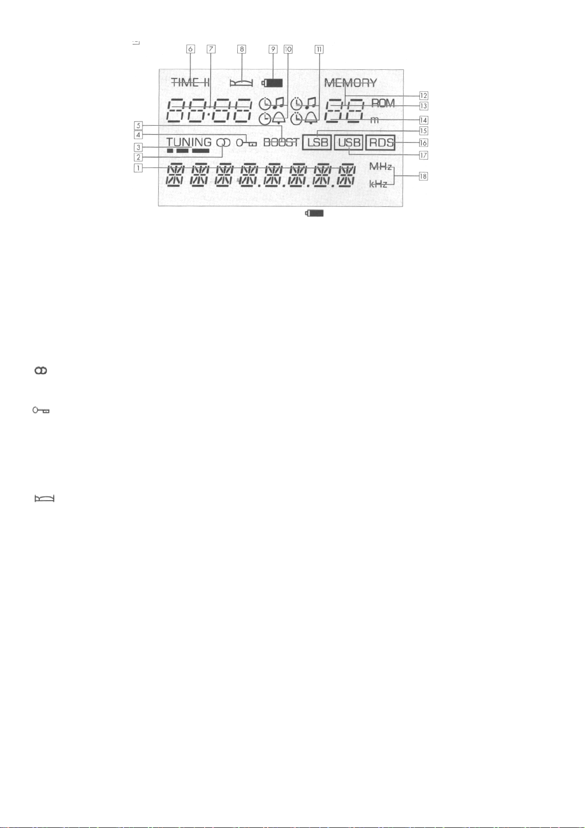
Indication(1)-(18)
Yacht Boy 500 - LC DATA MONITOR (Display)
1 8-digit alphanumeric display for
- Station name
Appears automatically when receiving an FM (VHF)
station which is transmitting RDS (Radio Data System)
signals. For other stations, you can enter a name of yo ur
choice.
- LW (Longwave), MW (Mediumwave), SW (Shortwave),
and FM (VHF) : waveband, frequency.
- Programming functions
e.g., △ MENU
- Hints (marked by *)
e.g., * LOCKED, ;
- Error messages (marked by **) e.g.,
e.g.,** MEMORY, ** FREQ, etc.
- Automatic switch-on times.
2
(FM stereo reception).
3 TUNING (field strength indication)
4
(Key-protect= key locking).
5 BOOST (increased output power).
6 TIME I1/TIME II (related to the indication ).
7 - Clock times (TIME I/TIME II), SLEEP time (go-to-sleep
time), alarm times.
8
- one SLEEP time (go-to-sleep time) is programmed. SNOOZE (alarm interrupt) is activated.
▽
, ON 1, OFF 1, etc.
*
NO RDS, Q - - (RDS quality), etc.
9
(battery check)
1 0 Symbols for alarm modes (wake-up b y r a d i o
programme or alarm sound signal alarm time 1).
1 1 Symbols for alarm modes ( w a k e -up b y radio
programme or alarm sound signal alarm time 2).
12 1 - 40 MEMORY (numb er of s tati on mem ory lo cation) .
13 1 - 9 ROM (ROM table is selected).
14 SW-Meter-Band
AS (AUTO SEARCH) = Automatic Station search.
0 = Tuning memory.
AF = RDS Alternative Frequency.
15 LSB (Lower Side Band):
Lower side bond on SSB reception.
SSB = Single Side Band.
16 RDS (Radio Data System): You are receiving an F M
station broadcasting RDS signals.
17 USB (Upper Side Band)
Upper side band on SSB reception.
18 MHz - kHz (frequency)
In MHz on FM (VHF), in kHz o n AM (LW, MW, SW).
3
Page 4

Your Unit at a Glance
(1) Illumination Button (LI GHT)
- For switching on the display illumination on battery
operation (permanent illumination on AC (mains)
operation).
(2) SNOOZE Button
- To interrupt (press briefly) and switch off (lo nger
pressure) the sound signal during the alarm function.
(3) Telescopic Aerial/Antenna
- For FM (VHF) and SW reception.
- Can be extended and swivelled.
(4)LC DATA MONITOR (Display)
(5) Numeric Buttons 0 ... 9
- For all numeric entries.
- Press 0 / R O M button a longer time :
Passage from the ROM table to the normal memory
level and back again, with tansfer into the tuning
memory.
(6)MEMORY Button
-For calling up the station memory locations 1 ... 40
(enter with the numeric buttons 0 ... 9).
- For calling up the tuning memory 0.
- For calling up the ROM table 01 ... 09. Memory-Scan
Press briefly: To step to higher memory location numbers;
Press a longer time: To step back to lower memory location numbers.
(7)Volume Control (VOLUME)
(8)CLEAR Button Press b r i e f l y :
- To clear wrong entries.
- To quit the menu functions.
- To abort entry of abbreviations. Press a very long time:
- To clear an occupied station memory location.
(9)Swing-out Support
in the rear of the unit.
- To bring the unit into a tilted position convenient for
operation.
(10) Battery Compartment
in the rear of the unit.
(11)On/Off Button ( O N / O F F )
combined with the locking switch (LOCK/UNLOCK).
(12)Fine Tuning Control (FINE T UNING)
for AM (MW, LW, SW) and SSB reception.
(13)
on.)
(14) SLEEP Button (go-to-sleep button)
( 1 5 ) FM/RDS-AF Button
(Key-protect = locks keys when unit is switched
- This prevents an indadvertent use of the function
keys.
- Switching off is possible: set switch j to "LOCK".
- For entering a period of time of up to 60 minutes in
steps of 10 minutes, after which the radio switches
off.
- For selecting the FM (VHF) band.
You will hear the F M station last tuned to (Last Station
Memory).
- For concluding a manual frequency entry.
- For calling up the AF = Alternative Frequencies which
can be received via RDS (Radio Data System) when this
band is already selected.
Press briefly = AF forward,
press a longer time = AF backward.
(16) TIME I/II
- To switch between time zone I and time zone II.
- To transfer a manually entered time into the
actual time zone.
- To conclude a switching time I or II entry.
(17) AM Button
Press br i e f l y :
- To select an AM band (LW, MW, SW).
Further pressures on this button will step through the
AM band s in the o rder L W -* MW - SW -> LW -*
MW, etc.
You will hear the station last tuned to in the respective
AM band.
- For concluding a manual frequency entry.
- For concluding a manual band entry.
Press a long e r time
- On SW, stepping to the lower band limit of the following meter band as long as this button is kept pressed.
(18) AUTO Button
- For enabling and disabling the automatic functions
after having set the alarm mode, the switching times and
the station memory.
(19) TUNE △/TUNE ▽
On FM:
Press briefly:
- Frequency tuning in the 25 kHz mode.
Press a longer time:
- Station search in the 100 kHz mode.
TUNE△= to higher frequencies.
TUNE▽=to lower frequencies.
On MW and LW:
Press briefly:
- Frequency tuning in the 1 kHz mode.
Press a longer time:
- Frequency tuning in the 9 kHz mode.
On MW, the Menu allows you to switch to the 10 kHz
raster (USA mode).
Press a very long time:
Automatic frequency scan.
On SW:
Press briefly:
- Frequency tuning in the 1 kHz mode.
Press a longer time:
- Frequency tuning within a meter band in the 5 kHz
mode.
Press a very long time:
Automatic frequency scan.
(20) MODE Button
Press briefly:
- To temporarily switch from name indication to
frequency indication.
On SW, additional indication of the meter band.
Press a longer time:
- To call up the menu.
(21) MONO/ROM-AF Button -
-Mono/stereo switching.
-To call up alternative frequencies with the "ROM
table" selected.
4
Page 5

(22)LSB/USB Button
- To select the lower or upper side band on SSB (Single
iSide Band) reception.
Stepping button, steps forward in the order:
With reception frequency < 10 MHz = LSB Æ USB Æ
Normal Æ LSB, etc.
With reception frequency ≥10 MHz = USB Æ LSB Æ
Normal Æ USB, etc.
LSB = Lower Side Band;
USB = Upper Side Band.
On FM:
Keep pressed button = indication of the RDS quality
(23) STORE Button
- For storing the displayed frequency or the station
name and the selected reception mode (e.g., Mc Stereo,
LSB/USB) into one of the station memory locations 1 ...
40.
Press briefly: Store compare.
- Indication whether the frequency tuned to has ready
been stored (e.g., *MEMO 3 ... MEMO5 …
MEMO8 ... ).
- Further pressures on the button or keeping it press
indicates whether the respective frequency is stored
several times and, if so, on which location numbers.
- If the frequency is not yet stored, the display (4)
indicate * NEW.
Press a longer time:
- Indication of all free memory locations
(e.g., * FREE 6 ... FREE 8 ... FREE 25 ... ).
(24) A - Z Button
- To enter the abbreviation for the currently selected
station memory location.
(25) SOUND (NORMAL -BOOST)
not on headphone operation.
NORMAL = normal output power
(low-current drain on battery operation);
BOOST= the output power is more than
doubled(recommended on mains unit operation).
(26)TONE (MUSIC - SPEECH)
MU S IC = normal reproduction;
SPEECH = speech reproduction.
(27) Headphone Jack (Ω)
- For stereo headphones with 3.5 mm jack plug and an
impedance of 32-2000Ω.
FM stereo reception is only possible with a headphone.
When connecting a headphone, the built-in loudspeaker is automatically disconnected.
(28) 3.5 mm Output Socket (LINE OUT)
- High-level output for making recordings.
( 2 9) 3.5 mm Output Switch Jack (
- For controlling external units (e.g., a tape deck).
(30) 3.5 mm Coaxial Socket (DC I N 9V
- For connecting the mains unit accompanying the unit (AC
adapter NR 90-1).
)
)
5
Page 6

for all wavebands
Telescopic aerial(3)
for FM and SW receptio n.
• When the aerial base is completely pulled out, the
telescopic aerial can be tilted and rotated into different positions.
• For SW reception, fully extend the aerial and place it ver-
tically.
Due to the much more better propagation conditions during the evening and night hours, there may be interferences during these hours.
• These interferences can be reduced by partially pushing in
the telescopic aerial.
Please note
Touching the telescopic antenna reduces FM and SW reception
quality.
Ferrite aerial
for MW and LW reception (built-in).
• Turn the unit about its vertical axis to find the best
reception position.
Aerials
6
Page 7
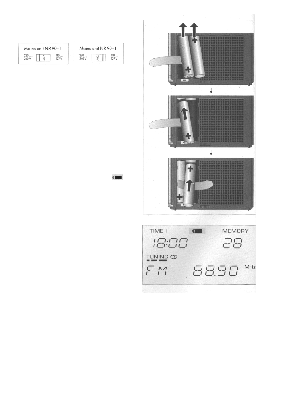
AC (Mains) Operation
• Only use the supplied AC (mains) unit NR 90-1 for the
set.
• Adjust the local mains voltage on the AC (mains) unit.
220... 240V 110 ... 127V
Power Supply
• Connect the mains unit to the DC IN 9 V socket(30)
(3 0). This automatically disconnects the inserted
batteries.
- No responsibility can be accepted for damage due to
operation with the voltage selector set to the wrong
position.
• Remove the batteries if the unit is to be operated perma-
nently on the mains!
Battery Operation
With four 1.5 V batteries, type IEC LR 6 or AA.
We recommend the use of alkaline-manganese batteries
with low mercury constituent or no mercury at all.
• Disconnect the plug of the AC (mains) unit from the DC IN
9 V socket (30).
• Open the cover of the battery compartment (10)
(on back of unit).
• Insert the batteries with correct polarity
(see scheme on bottom of battery compartment).
• For this, observe the order of the batteries and the posi-
tion of the take-out ribbon (see Fig. to the right)
Battery Check
When the batteries get weak, a battery symbol ( )
will appear in the display (4).
7
Page 8

Attention
• Remove exhausted batteries immediately from the unit!
• If the unit is not to be used for longer periods, remove
batteries even if they are new!
- No responsibility can be accepted for damage due to
leaking batteries.
Note on environmental protection
Do not throw exhausted batteries in the houshold waste !
Hand over the old batteries to your radio dealer or a public
collecting point when buying new ones.
Data Protection
(Mains and Battery Operation)
• When the power supply is disconnected, the time and the
last station memory are retained for approx. 5 minutes.
Reset Button
If, due to external interferences (caused by static charges
of carpets, thunderstorms, etc.), the control electronics of
your Yacht Boy 500 should receive wrong information signals, or if no entries at all are possible, then press the Reset
button.
This is to be found behind the top right opening in the de-
corative speaker grill.
For pushing the switch, it is best to use a bent-up paper clip.
By releasing the Reset impulse, the unit is reset to its initial
programming state.
The contents of the individual station memory locations are not
affected.
However the time setting and the contents of the last station
memory will be cleared.
The stored stations and menu options will not be lost neither by a
power supply failure nor by a Reset.
8
Page 9
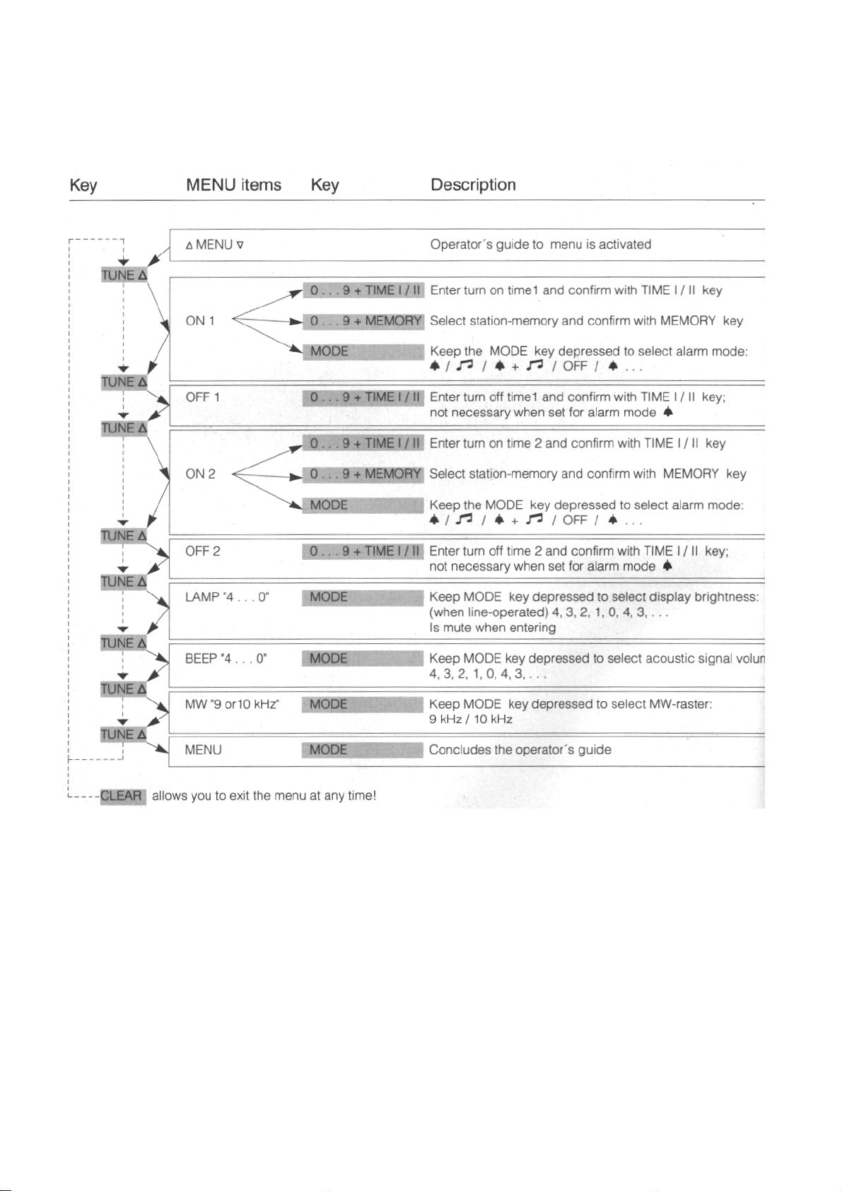
User Guide Via the Menu
With the unit switched on, call up the menu by pressing the
MODE button (press a longer time).
Use the buttons TUNE △ and TUNE ▽ to select one after
the other the different menu options:
Switch-on time ON 1- switch-off time OFF 1 -
Switch-on time ON 2 - switch-off time OFF 2 -
iDisplay brightness - LAMP 0 ... 4 Sound signal intensity BEEP 0 ...4 -
MW raster frequency 9 kHz or 10 kHz.
You can quit the menu ...
- by pressing the CLEAR button,
- automatically 60 seconds after completion of the 1
entry,
- by pressing the MODE button when the display sho
△
MENU▽ .
,
9
Page 10

General Operation
For convenient operation, your Yacht Boy can be brought into a
tilted position by the swing-out stand provided at its rear.
• The type plate is to be found below-this stand.
• To switch the unit on or off, press the ON/OFF button
(locking switch (11) in "UNLOCK" position).
Key-protect
• By pressing the button (13) (indication in the
display (4)), it is possible to "lock" the function
buttons on the front panel when the unit is switched on,
thus preventing an inadvertent use of these buttons.
• Press once again on the button to "unlock" the function
keys.
LOCKED
• To protect the unit against inadvertent switching on during
transportation, set the switch (11) to "LOCK". (Indication
I LOCKED in the display (4)).
This disables all functions of the unit, such as the alarm
function.
However, the function settings are retained.
• To clear the "LOCKED function", set the switch (11) to
"UNLOCK". The indication * LOCKED must disappear.
Direct Entries
• You can enter all numeric values with the numeric buttons (5)
Frequencies, station memory locations (programming or
calling up), SW meter bands, clock times and switching
times.
Yo u dispos e of appr ox. 60 seconds for each ent ry st ep. If
you exceed this period of time, you are obliged to restart.
When operating the unit via the menu, the unit switches
automatically to radio operation approx. 60 seconds after
having made the last entry.
• You must always conclude (confirm) your entries with one of
the fo llowi ng bu ttons : FM/RDS-AF, AM, STORE, MEMORY and
TIME I/TIME II.
• To immediately correct a bad entry which is not yet con-
firmed, press the CLEAR button (8).
• If you make a wrong entry or an operating error, a hint o r
an error message will appear for approx. 2 seconds in the
d i s p l a y ( 4 ) after having concluded the respective entry or
operation.
In addition, the unit emits a beep.
If you wish to switch off the beep or change its volume, follow
the "User Guide Via the Menu", page 38.
Defintion of times you must press the buttons
Longer = 300 ms
Long = 500 ms
Very long = 2 s (the function will be confirmed by a beep).
10
Page 11

Hints and Error Messages in the Display (4)
Hints (marked by *) Error Messages (marked by **)
* RDS
* NO RDS
* NO AF
*MEMO- -
* NO MEMO
* NEW
* FREE - -
* FULL
* LOCKED
* KEY
Entry of abbreviations disabled.
The station is not broadcasting RDS signals, or
the received signal strength does not meet the
RDS requirements.
The station is not broadcasting alternative
frequencies.
The current frequency is already stored in the
station memory location - - .
No or no further station memory locations are
occupied.
The current frequency is not yet stored
The selected station memory location - - is not
occupied.
All locations of the station memory are
occupied.
The locking switch is set to "LOCKED".
All buttons are protected by "Key-protect".
** TIMER
** TIME
** FREQ
** M - BA ND
** MEMORY
** ROM TAB
No automatic function possible without
entry of alarm mode.
Clock or switching times not correctly
enter ed.
Frequency not correctly entered
SW -m-band not correctly entered.
Station memory location not correctly
entered.
With the ROM table being selected, the
"STORE" button has no fu nction.
11
Page 12

Display Illumination
O n battery operation, you can switch on the illumination for approx.
15 seconds by p r es s i n g the L I G H T b u t t o n ( 1 ) . W h e n a c t u a t i n g
buttons on the set ("operations"), this period will be
prolonged.
You can immediately switch off the illumination again by pressing the
LIGHT button (1) once again.
• On AC (mains) operation (unit "on"), you have the choice
between switched on or switched off illumination.
• On AC (mains) operation (unit "off"), you can select the desired
degree of brightness. (See "User Guide Via the Menu").
On AC (mains) operation, it is possible to temporarily switch on the
illumination as on battery operation when the
permanent illumination is switched off.
The Volume
• can be adjusted with the VOLUME slider control (7).
• SO UND switch (25)
(indication in display (4))
The output power is more than doubled.
Because of the higher current drain, this mode is only
recommended during AC (mains) operation.
set to BOOST
The Tone
• can be adjusted with the TONE switch (26) to suit your
taste:
MUSIC = normal reproduction;
SPEECH = s p e e c h r e p r o d u c t i o n .
Waveband Selection
When switching the set on with the ON/OFF button, it is
ready for reception and you will hear the station last tuned to.
FM
The FM band is selected with the FM/RDS-AF b u t t o n .
AM
The AM band is selected with the AM button.
- The first pressure on the AM button selects the station last tuned
to in the AM band.
- Each further pressure on this button steps through the AM
bands in the order
and selects the station last tuned to in the respective band.
LW Æ MW Æ SW Æ LW Æ MW Æ ,etc.,
12
Page 13

ROM Table of the Yacht Boy 500
When receiving FM stations which are normally supposed to
service relatively small areas, you can expect an equally good
reception quality all over the day. With some restrictions, this
applies also for local LW and MW stations.
When receiving SW stations, the signal has covered in most
cases very long distances.
Due to physical laws, the same constantly good reception
quality as known from local reception can thus not be
guaranteed for SW reception.
Most radio stations which operate with SW are broadcasting
their programmes on several frequencies. Through this
distribution onto several SW bands, the best propagation
conditions during the different times of day and even during
different seasons are used.
To offer you a most convenient operation also when receiving
on the SW bands, your GRUNDIG Yacht Boy 500 has been
provided with a memory containing a ROM table (ROM =
READ ONLY MEMORY), into which 90 frequencies of 9 radio
stations which are operating all over the world are stored.
If you wish (press the MODE button (20)), the display will indicate the frequency currently tuned to (see list) beside the
country sign and the station abbreviation.
Selecting Frequencies
For the table, frequencies have been selected on which ma i n l y
programmes in the respective national languages,
but also service programmes for foreigners in the corresponding language (partly also in German) are broadcasted.
Despite of the up most care taken over the selection of the
frequencies, it may happen, when calling up a memory location, that ...
a) you hear a different station than that indicated in the display,
b) you hear only disturbing noise.
In the first case, the cause is to be found in the multiple use
of certain frequencies.
In the second case, there are several causes possible. For
example, that...
- the station concerned is currently not broadcasting on this
frequency,
- the station has temporarily exchanged this frequency with
another frequency, or
- the current reception conditions for the area
concerned are very bad
.
In such cases, it is recommended to call up (interrogate) all
alternative frequencies stored for the station concerned (for
this, use the MONO / R O M - A F button ( 2 1 ) ) .
For detailed information about programmes, broadcasting times, and
eventually changed frequencies, please contact the respective radio
stations.
We are sure that, with this ROM table, we have placed a means
at your disposal which offers you the possibility of quickly and
securely tune to worldwide operating SW Stations, even if
you have only little experience in short wave reception.
13
Page 14

Calling Up ROM Table Memory Locations
For calling up stations stored in the ROM table, you must
enter the code number (station code) given in the list below.
This means that you must always enter a zero followed by
the number and confirm the entry by pressing the MEMORY
button (6).
If you have already called up the ROM table, you can
select further stations with the MEMORY button (6):
Brief pressure = you get to the next higher station code.
Long pressure = you get to the next lower station code.
For all radio stations, several alternative frequencies have
been programmed. You get to these alternative frequencies
with the MONO /RO M-A F button (21). Each short
pressure on this button will switch to the next frequency.
A direct frequency entry via the numeric keypad (also when
changing the waveband) or a frequency change does not
yet cause the exit from the ROM table.
If you have meanwhile changed the frequency, pressing the
MEMORY button (6) brings you back to the starting point
of the ROM table.
You can quit the ROM table by selecting a station memory
location (e.g., 1 MEMORY) or by slowly pressing the
0/ROM numeric button which causes in addition the
transfer
into the tuning memory.
Code Station abbrev. Station Frequencies (kHz)
01 DW . . . . . D Deutsche Welle 3995, 6075, 9545, 9735, 11795, 13780, 15270, 15275,
15350, 15410, 17845, 17860, 21540, 21560, 21640, 21680
02 BBC . WS . G BBC London External Services 3955,3975,5975, 6045, 6180, 6195, 7325, 9410,
9750,9760,9915,12095,15070,17640, 17705, 25750
03 ROEI . AUT Ra d io A ustr i a I n tern a tiona l 59 45,6155,9870, 13730, 15410, 15430, 15450, 21490
04 SRI . . SUI Sw iss Rad io Int e rnat iona l 39 8 5 ,6165,9535, 9885, 11955, 12030, 15570
05 REND . HOL Ra dio Nede rlan d 5955,6020,9860, 9895, 13700, 15560, 17575, 17605
06 RFI . . . . F Ra d io Franc e In t erna t ional e 3965 ,6175,7135, 7280, 9790, 11705, 15300, 17620
07 RAI . . . . I Ra diot el ev is io ne I talians 5990,6 060,7175, 7275, 7290, 9515, 9575, 9710
08 RMWS.RUS Radio Moscow 5905,5915,7360, 9880, 12010, 13710, 15140, 15225,
15540,17645, 17850, 21725
09 REE . . . . E Radio Exter ior de Espa na 7105, 9685, 9875, 12035, 15365, 17715, 17890
14
Page 15

Step by Step into the World of Shortwave Reception
1. Insert batteries or connect the AC (mains) unit.
2. Extend the telescopic aerial (3).
3. Switch the unit on with the ON / O F F butt on (11) .
4. Adjust the volume with the VOLUME slider control (7).
For your first experience with SW reception, proceed step
by step as shown below
On which frequency(ies) you then can receive, for example,
BBC London, depends on the time of day.
Select "your" frequency(ies) out of the 16 preprogrammed
frequencies.
Please note:
Beside the indications given in the example, no further indications
should be visible in the display.
The time indication (TIME I/II) is meaningless in this case
15
Page 16

Tuning to Stations with the TUNE A/V buttons
• Switch the unit on with the O N / O F F b utton (11 ) .
- The frequency tuned to appears in the display, on FM in
MHz, on AM in kHz.
- A separate tuning memory is provided for each waveband.
1. Frequency Tuning in the FM Band
• Select the FM waveband.
- You hear the station last received in the FM band.
• You tune to the desired station by briefly pressing one of the
buttons TUNE △ or TUNE ▽ (19). Each pressure on the
button changes the tuning frequency by 25 kHz.
• A longer pressure on one of the buttons TUNE △ or TUNE
▽ (19) starts the automatic station search.
TUNE ▽ =the search is started in direction of lower
frequencies.
TUNE △ =the search is started in direction of higher
frequencies.
- The station search operates in the 100 kHz mode.
- The display (4) indicates AS (Auto-Search) = automatic
station search.
The automatic station search will stop as soon as it has found
a station appropriate for good reception. It then can be
restarted by a longer pressure on one of the TUNE /△▽
buttons.
If the found station is an RDS station, the RDS symbol and the
station name (see "Special Funct ions on FM") will be displayed
after a few moments. In addition, the display (4) indicates O
for the tuning memory, and you will hear the station.
16
Page 17

Tuning to Stations
2. Frequency Tuning in the AM bands
• Select one of the AM bands.
- You will hear the station last tuned to in the respective AM
band.
MW and LW
• Tune to the desired station by bri ef pressures on one of the
buttons TUNE △ or TUNE ▽ (19). Each pressure on one of
the buttons changes the tuning frequency by 1 kHz.
• Each longer pressure on one of the buttons TUNE /△▽
increases or decreases the frequency tuned to by 9kHz (on
MW, this can be changed to 9/10kH z via the menu).
• If a frequency lying outside of the frequency raster has
been tuned to before pressing one of the TUNE /△▽
buttons, the unit automatically tunes to the next raster
frequency in the respective direction.
• A very long pressure on one of the TUNE /△▽ buttons
starts the frequency scan (station search) in the desired
direction. Each frequency then will be heard for approx. 1
seconds. Pressing a random button will abort this function.
SW
• A longer pressure on one of the TUNE /△▽ b u t to ns will
step 5 kHz down or up within the selected m-band. In the
amateur bands, the tuning mode is 1 kHz.
If the current frequency lies beyond the limits of a meter
band, the unit automatically tunes to the limit (cut-off)
frequency of the next adjacent m-band. When the end of
a band is reached, the unit jumps to the beginning of the
same band.
A very long pressure on one of the TUNE /△▽ buttons will
start an automatic frequency scan in 5/1 kHz steps up or
down within the selected meter band. Each raster
frequency then will be heard for approx. 1 seconds.
Pressing a random button will abort this function.
• Long pressure on the AM button: Switching to the lower
limit (cut-off) frequency of the following m-band.
Tuning to S tati o ns wi th th e Num eric Butt ons
(Direct frequency entry)
For this, you must know the frequency of the station you
wish to tune to. You can find these frequencies in station tables or
radio guides. You can enter the desired frequency in
MHz or kHz, or as m-band in the case of SW stations.
• Confirm each entry wit the buttons
FM/RDS-AF for FM or
AM (17) for LW, MW and SW.
On FM: MHz indication
On AM: kHz indication
The display (4) indicates 0 for tuning memory and you hear, the
station.
Examples:
desired frequency entry order
99.00 MHz
99.00 MHz
99.00 MHz
99.00 MHz
99.00 MHz
99.00 MHz
7000 kHz
99 Æ FM/RDS-AF button
990 Æ FM/RDS-AF button
9900 Æ FM/RDS-AF button
991 Æ FM/RDS-AF button
9910 Æ FM/RDS-AF button
99100 Æ FM/RDS-AF button
7000 ÆAM button
17
Page 18

Entering a Meter Band
Entering a Meter Band on SW
Entered numbers below 100 wi th subs equ ent co nfi rma tio n b y the
AM button (f~ will be recognized as wavelength in meters for
SW
When the entry is valid, the set will tune to a frequency next to
the band centre in the case of radio bands, and to the beginning
of the respective SW band in the case of amateur bands.
See table to the right.
It is possible to enter the following meter bands
10, 11, 12, 13, 15, 16,17, 19, 20, 22, 25, 30, 31, 40, 41, 49, 60, 75, 8 0 , 90 .
Entry example for the 49-m band:
Numeric buttons 4 9 Button AM Æ 6075 kHz
(= Deutsche Welle).
Indication of the actual band on SW
• With direct band entry or with SW frequency scanning
(within a meter band): The selected band is permanently
indicated.
• With direct frequency entry or manual tuning: If the
frequency tuned to lies in one of the above listed meter
bands, the band will permanently be indicated in the
display, if not, the display indicates 0.
• It is possible to briefly (approx. 4 seconds) indicate the
m-band by pressing the MO DE button.
Band(m)
90-m-tropic 3200 3300
80-m-amateur 3500
75-m-radio 3950 3975
60-m-tropic 4750 4905
49- m - r a d i o 5950 60 75
40- m - r a d i o 7000
41- m - r a d i o 7100 72 20
31-m-radio 9400 9635
30-m-a m a t e u r 10100
2 5 - m - r a d i o 11650 11845
22 - m-r a dio 13600 13700
20-m-a mateur 14000
19 - m - r a d i o 15100 15320
16 -m-r adi o 17550 17705
17-m-amateur 18065
15-m-amateur 21000
13 - m - r adio 21450 21690
12-m-amateur 24890
11 -m-radio 25650 25820
10-m-amateur 28000
* Not all radio stations are broadcasting 24 hours a day and
during all seasons programmes on this frequency. For this
reason, please note the individual broadcasting times.
Lower cut-off Radio station Band
frequency (kHz) or band centre
18
Page 19

Storing in Memory General
What can You Store?
You can programme up to 40 station memory locations in
random order, also mixed from the 4 wavebands FM - M W -LWSW.
You can store in memory each frequency you have tuned to.
The associated operating states (mono/stereo, LSB/USB) are
automatically stored with the frequency.
On each station memory position, you can store in addition - even at
a later date - an alphanumeric abbreviation (e.g., station name) of
up to 8 positions.
With FM-RDS stations, the station name is automatically displayed
and transferred into the respective station memory location when
storing the station.
Is the Frequency Tuned to Already
Stored in Memory?
Store Compare
• Before storing a frequency tuned to in memory, you can check
whether this frequency is already stored, by briefly pressing the
STORE button.
- If the station is already stored in memory, the display indicates the
station number (e.g., * MEMO 12). If you press the STORE
button once again or keep it pressed while this indication is
visible, all further stations with this frequency will be indicated.
- If the station is not yet stored in memory, the indication * NEW
appears in the display.
• A long pressure on the STO RE button will indicate the free
memory positions (e.g. * FREE 9). If you press the STORE
button once again or keep it pressed while this indication is
visible, all free memory locations will be indicated.
- If all locations of the station memory are occupied, the indication
* FULL will appear in the display.
19
Page 20

Checking the Desired Station Memory
Position
To avoid accidentally erasing an already stored station be, yo u
can call up the memory location you wish to use and check
it before you store it in memory. When doing this, the station
to be stored remains in the tuning memory (0 in the
display)
• Enter the number of the station memory location with the
numeric buttons.
• Press the MEM ORY butto n.
The display then indicates either * FREE (not occupied)
or, if a station has already been programmed, the number of
the station memory location and the frequency or the
name of the station.
The station last tuned to in the respective waveband remains always "buffered" on the numeric button "0".
• It is then eventually necessary to press the AM button several
times or to switch to FM to return to the desired
waveband.
Then retrieve the station by pressing the numeric button
"0" and the MEMORY button, and search a different station memory location.
Programming a Station Memory
Location
Overwriting the old memory contents.
• Tune to the desired station.
• Enter the number of the desired memory location with the
numeric buttons.
• Press the STORE button a long time.
- The number of the selected memory location appears
below the indication MEMORY in the display. You will still
hear the stored station.
- A station name which you have entered or which has
been decoded by the RDS system and which is visible in
the display will be stored along with the frequency.
20
Page 21

Entering Abbreviations
(e.g., station name)
On each station memory location (1 ... 40), a station
name (up to 8 positions) which then is indicated in the
display can be programmed along with the frequency.
This is possible either when storing the frequency or at
a later date. Examples for station names are WARSAW,
HELSINKI, BUDAPEST, etc...
• The entry is initialized with the A - Z button.
• If the hint *RDS or * ROM TAB appears after having
pressed this button A - Z, entry of the abbreviation is
inhibited.
• If entry of the name is possible, the radio will continue
to play on the chosen station. The cursor will flash at
the left in the display.
• The TUN E △/ ▽ buttons allow you to enter letters (A-
Z), figures (0-9), and several special characters.
• Each pressure on the A - Z button moves the cursor
one position to the right for entering the next
character. A longer pressure on the button moves the
cursor to the left thus allowing you to correct a wrong
entry.
• If you wish to enter spaces or less than 8 positions,
use the blank character (between 9 and A).
• After having entered the last position, press the A - Z
button once again. The cursor disappears and the entry
is allocated the station memory location.
• When pressing the A - Z button once again, the cursor
reappears at the first position, and you can, for example,
correct the entry.
Exiting this function with the CLEAR button:
• The entry is not stored in memory.
When surpassing the timeout of > 15 seconds:
• The actual entry is automatically stored in memory.
Calling Up Stored Stations
• Enter the number of the desired station memory
location with the numeric buttons.
• Press the MEM ORY b utto n .
- If the called up memory location is not programmed with
a station, the indication * FREE appears for approximately 2 seconds in the display.
You will still hear the station tuned to before.
- When calling up stored stations with the numeric
buttons, the unit automatically switches to the correct
waveband (Intermix function).
21
Page 22

The MEMORY Button (Memory Scan)
This button allows you to call up occupied memory locations
one after the other:
Brief pressure on the button = memory location numbers up,
longer pressure on the button = memory location numbers
down.
The next possible memory position location is called up and its
name is indicated if it has been entered or if it is received via
the RDS system.
Unoccupied memory locations are automatically skipped.
Clearing an Occupied Memory Position
• A very long pressure on the CLEAR button will clear the
actual station memory location.
The display indicates
*
FREE and the station number.
22
Page 23

Going to Sleep to Radio
The SLEEP button allows you to enter a "go-to-sleep time"
(time the radio will still play) of up to 60 minutes.
• Press the SL E EP button . The unit is switched on.
• Repeated pressures on the SLEEP button increase the playing
time in 10-minutes steps (up to 60 minutes). Indication: 10,
20, 30, 40, 50, 60, 10, 20, etc...
• A longer pressure on the button increases the playing time
automatically in 10-minutes steps.
- The display indicates the symbol and the entered
"go-to-sleep time".
- When this time has elapsed, the unit automatically switches
off and the indication
Checking the playing time:
• Briefly press the SLEEP button. T h e d i s p l a y i n d i c a t e s t h e
time remaining until the unit is automatically switched
off.
Premature erasure of the playing time:
• Switch the radio off with the ON / O F F button or press the
SNOOZE button.
disappears.
23
Page 24

The Clock
• The timeout (period during which you must complete each
entr y) of app rox. 60 seconds app l ies a l so for t he clock.
• You can enter times whether the radio is switched on or off.
• You can enter clock times and switching times in several
different ways.
Examples: Entry sequence
Clock time 630
1 st example: Clock time 6.30 0630
2nd example: Clock time 15.00 15
1500
3 r d e x a m p l e : C l o c k t i m e 0 . 1 5 015
0015
Setting the Clock
(TIME I/Clock time I) with the help of a reference clock.
Example TIME 1: 6.30 hours:
• The display must indicate TIME I.
• Enter the clock time with the numeric buttons.
• Press and hold down the TIME I/II button until the refer-
ence clock jumps from 6.29.59 to 6.30.00.
- As soon as you release the TIME I/II button, the clock
starts running right on the dot and the colon between the
hours and the seconds indication will flash.
Setting the Clock
(TIME II/Clock time II).
For setting TIME II/Clock time II proceed in the some way, with the
only difference that the display must indicate TIME II.
As the seconds of clock time II run synchronously with clock
time I, you must not wait for the minutes change-over in this
case.
Clock Time Indication TIME I/II
• Repeated pressures on the TIME I/II button (without pre-
ceding number entry) will switch between the two clock
time indications.
24
Page 25

Automatic Functions Timer ½
For the function "wake-up by the radio programme", you can enter
two independent switch-on and switch-off times. Each switch-on
time can be assigned to a different radio station.
For example, you can let your radio switch on to your favorite
station by the switch-on time 1.
If you wish then to hear a programme (e.g., the latest news)
broadcasted by a different station after switching on by switchon time 1, select this programme with switch-on time 2 and switch-off
time 2.
When the switch-on time 2 then is reached, you will hear the
desired station until the radio is turned off by the switchoff time 2.
Then the radio continues playing your favorite programme until
the switch-off time 1 is reach ed.
Please note ...
if both switching times are programmed and overlap each other:
- Switch-on times have always priority over switch-off times.
- The second switching times have priority over the first switching
times.
Already programmed stations are not affected by time programming.
The switching times always refer to the times indicated in the
display (TIME I or TIME II).
An example for better understanding:
You have programmed the local time (e.g., CET or CEST) as TIME I.
TIME II stands for a second time zone (e.g., Greenwich M ean
Time/GMT).
You have entered 14.00 hours as switch-on time and set the radio to
"AUTO".
If then the display indicates TIME I, the radio will be switched on at
14.00 hours local time;
if the display indicates TIME II, the unit will be switched on at
14.00 hours of the second time zone.
Programming Switching Times
Switching Times 1/2
• Switch the radio on.
• Select the menu item ON 1 (switch-on time 1).
• Use the numeric buttons 0 ... 9 to set the desired switchon time and
confirm the entry with the TIME I/II button. The switch-off time is
automatically set so that one hour playing time is obtained.
• Enter the number of the desired station memory location with the
numeric buttons then press the MEM ORY butt o n .
• Repeatedly press the MODE button to select the desired wake-up
(alarm) mode:
N) n= wake-up by radio programme. You
hear the selected station.
U4= wake-up (alarm) by alarm signal. The radio station
• Repeatedly press the MODE button to select the desired wake-up
(alarm) mode:
= wake-up by radio programme. You
hear the selected station.
= wake-up (alarm) by alarm signal. The radio station is
muted and an alarm signal sounds instead.
and = wake-up by alarm signal and radio
programme. You hear the radio programme
and the alarm sound signal.
• Use the TUNE A button to select the menu function OFF 1 (switch-
off time 1).
25
Page 26

- You can enter a switch-off time of your choice with the numeric
buttons and the TIME I/II button. However, this does not apply for
the "wake-up by sound
signal" function .
• Use the TUNE A button to select the menu function ON 2.
• Press the CLEAR button to quit the menu (the entered data will be
stored in memory).
• For ON 2/OFF 2 applies the same as for ON 1 /OFF 1.
Checking the Switching Times 1 /2
• When you have selected the menu functions O N 1 or ON 2 and
OFF 1 or OFF 2, you can indicate in the display the switch-on
time, the station memory location, the alarm (wake-up) mode,
and the switch-off time by pressing the TUNE A/ V b u t t on.
Automatic Switching On and Off
- The AUTO button allows you to switch on and off the automatic
functions.
1. With radio programme
• The alarm mode or must be selected.
• Enter the desired switching times.
• Tune to the desired station or select the desired station memory
location and adjust the appropriate volume.
• Press the AUTO button to enable the automatic function.
- The radio is switched off if the current time does not lie within
the programmed automatic time period.
- The following indications are then visible in the display: TIME I or
TIME II
Clock time
Alarm mode
Switch-on time
• If you have selected no alarm mode, a hint with the error
message L TIMER will appear when pressing the AUTO button.
• It is of course possible to switch the radio on and off with the
ON/OFF button so that you can listen to the radio also at times
which are not lying within the automatic switching period.
• If 2 switching times are programmed, the display will indicate the
next switch-on time.
- At the programmed times, the radio will automatically be switched
on and off.
Prematurely switching off the radio:
• Press the O N /O F F bu tto n.
- The entered switching times are retained.
2. With alarm sound signal
and/or
• The alarm mode or must be selected.
• Enter the desired switch-on time.
• As the alarm signal has a fixed duration of 5 minutes, it is not
necessary to enter the OFF time.
• Press the AUTO button. If the radio is switched off, the
following indications an visible in the display:
TIME I or TIME II
Clock time
Alarm mode
Switch-on time
- At the programmed time, the alarm signal will sound for 5
minutes max.
and/or
26
Page 27

Automatic Functions
• Briefly press the SNOOZE (2) button
- The alarm sound signal will be interrupted for approx. 5 minutes.
- The
- This function can be repeated as often as desired.
• Press the SNO OZE bu t ton a lo n g t ime.
- The alarm signal will prematurely be switched off (for 24 hours).
- The programmed switching times are retained. 3. With
alarm sound siqnal and radio proqramme
• The functions "wake-up by radio programme" and "wake-up by
alarm sound signal" can be combined.
• Enter the alarm times as described under paragraphs 1 and 2.
Switching Off the Automatic Functions
• Press the AUTO button.
- The alarm mode indications must disappear.
- The programmed switching times are retained.
Timer Recordings
If you possess a cassette recorder with start/stop remote control
facility, you can use the switching times of the radio to switch on and
off the cassette recorder for recording radio programmes.
Proceed as follows:
• Connect the output switch jack (29) with the switch jack of
the cassette recorder.
symbol will be indicated.
Automatic Control of a Cassette Recorder
For this, you require an appropriate connecting cable. Please
contact your specialized dealer or the GRUNDIG After-Sales
Department.
To make recordings with the cassette recorder, the LINE OUT
socket(* of the radio must be connected with the LINE IN socket of
the cassette recorder.
• Switch the cassette recorder to recording-start. When the Yacht
Boy 500 is automatically switched on, the cassette recorder is
also automatically started and records the programme
broadcasted by the selected station.
27
Page 28

Special Functions on FM
RDS (Radio Data System)
RDS is a digital information system, the signals of which are
broadcasted in addition to the FM radio programme. Your radio is
equipped for operation with this information system. It evaluates
the codes for programme identification (PI), programme service
(PS), and alternative frequencies (AF).
It is thus possible for the radio to indicate the name of the
programme chain (stations broadcasting the same programme)
and to compare the different stations of the same programme
chain.
To ensure a correct decoding of the RDS signals, certain demands
are made on the reception quality of RDS broadcasts. This is
especially true when the telescopic aerial is used for reception.
The first condition for correct RDS reception is a sufficient signal
strength. This means that the TUNING (field strength) indication
should reach its maximum deflection. A further condition is the
indication of the RDS sign. If these two conditions are met, the name
of the programme chain will be indicated within 10 seconds. If this
should not be the case, decoding of the RDS signal is probably
impaired by multipath reception (reflections). In most cases, this
distortion is not signalled through an unstable TUNING (field
strength) indication. At the most, the RDS indication might be
unstable. In technical jargon, this effect is called
The RDS reception quality is insufficient.
A special function of your unit enables the indication of the RDS
reception quality.
Pressing the LSB/USB button © switches the eight-position
alphanumeric indication to the RDS quality indication:
Q ...........
Try to improve the RDS reception quality by changing the
position of the telescopic aerial (tilt and/or rotate). This means
that as many segments as possible should be indicated. The figure
shows the maximum possible number of 16 sensitivity grades
(vertical bars).
This indication corresponds to 100 % RDS reception quality
(respectively 0 % error rate).
Especially when operating the radio inside a building, the
location of the radio can be of great importance for the RDS
reception quality. If necessary, try to install the radio at a location
giving better results.
The RDS-Q special function remains effective for approx. 1 minute
and then automatically switches to the indication of the
programme chain name. It is also possible to switch the RDS-Q
indication to the programme chain name indication by pressing
th e LSB/USB butt on o nc e ag ain.
Please note:
The indication of the programme chain name is only effected if the
RDS reception quality is sufficient, and the indication of the RDS
quality is only possible if the RDS sign is indicated too.
Calling Up Alternative Frequencies (AF)
If the RDS sign and the programme chain name are both indicated,
you can call up the alternative frequencies of this programme
chain.
Pressing the FM/RDS-AF button starts scanning of t broadcasted
alternative frequencies.
During this function, the indication AF appears in the displ a y
(4).
The individual frequencies are then checked for their field strength
(worthy of reception or not). If the field strength suffices for correct
RDS reception, scanning is aborted. The respective frequency is
indicated and the unit switches off the muting function which has
been activated at the beginning of the scan (call-up) function. If
none of the alternative frequencies is worthy of reception the radio
tunes to the initial frequency again.
Hint
Short pressure on the FM/RDS-AF button =
the alternative frequencies are indicated in increasing
order.
Long pressure on the FM/RDS-AF bu tton =
the alternative frequencies are indicated in decreasing order
28
Page 29

Special Functions on AM
SSB (Single Side Band) Reception on SW
... is an additional function to "normal" radio reception.
• Switch the radio on and select a SW amateur band (SSB
stations are mainly broadcasted on these bands).
• Set the TO N E swi t c h ( 26 ) t o SPEECH.
• Use the TUNE /△▽buttons (19) to slowly scan the band
step by step for SSB stations.
When doing this, please note that the carrier is suppressed on SSB
broadcasts.
This means that reception is only possible when the transmitter is actually broadcasting a programme (mostly in
speech). During pauses, no tuning is possible. The TUN I N G
indication is of great help when searching SSB stations.
The TUNING indication deflects in the rhythm of the speech
(modulation) when an SSB station is received.
• As soon as a station is found - the speech is still unintel-
ligible - select the lower or upper side band with the
stepping button LSB/USB (22).
Tune to best intelligibility with the FINE TUNING control (12).
If you wish to terminate SSB reception, do not forget to
switch back to "normal" AM radio reception
• Repeatedly press the LSB/USB button until the LSB/USB
indication disappears.
Interferences
• If there are interferences on the AM (MW, LW, SW)
bands, you can optimize reception with the FINE TUNING
control (12).
29
 Loading...