

Grundig Yacht-Boy-50-WR-5405 Service Manual

Service Document
Exchange Set
YACHT BOY 50 WR5405
Service
Manual
Sicherheit
Safety
Materialnr./Part No.
720108000001
Dieses Service Dokument ist nur in Datenform verfügbar
This Service Document is only available as data
Änderungen vorbehalten/Subject to alteration
Made by GRUNDIG in Germany • HS-41 0404
http://www.grundig.com
Es gelten die Vorschriften und Sicherheitshinweise
gemäß dem Service Manual "Sicherheit", Material-
S
nummer 720108000001, sowie zusätzlich die eventuell abweichenden, landesspezifischen Vorschriften!
The regulations and safety instructions shall be
valid as provided by the "Safety" Service Manual,
S
part number 720108000001, as well as the
respective national deviations.
ǵ
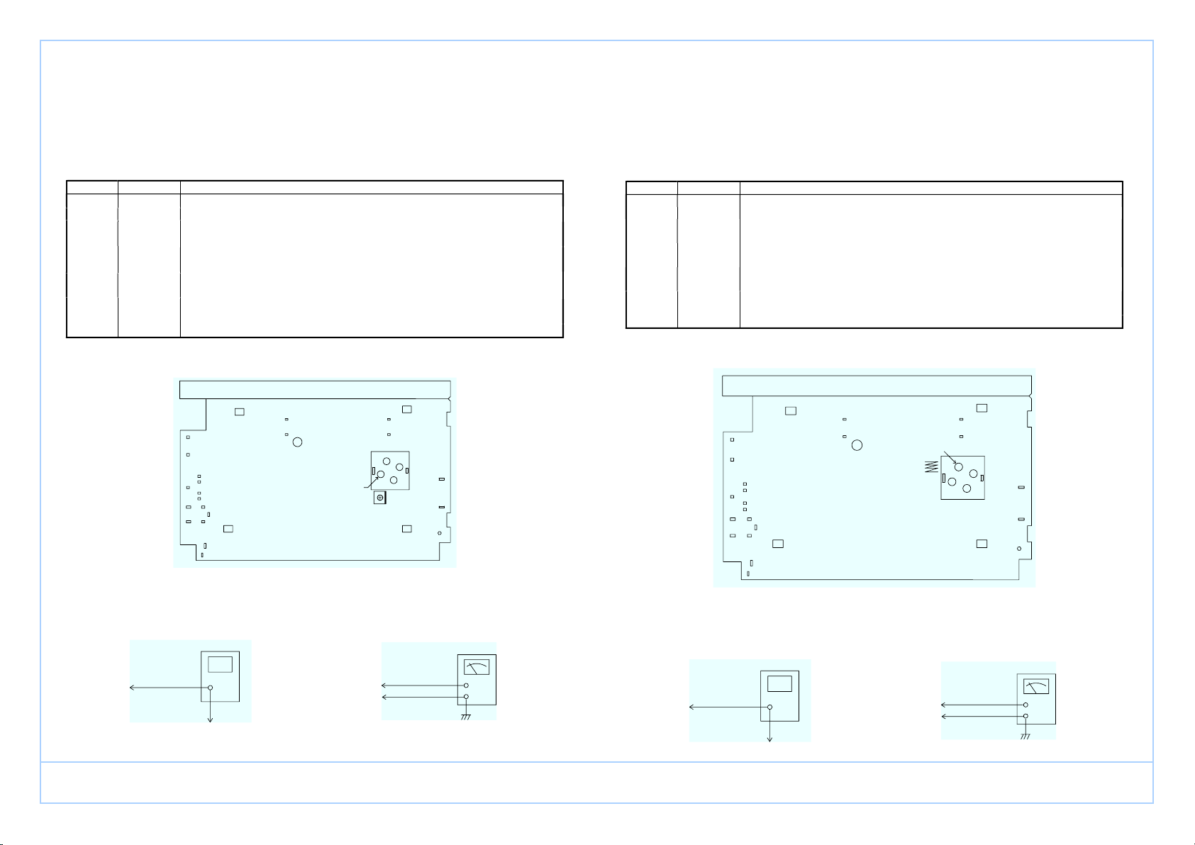
(2) ALIGNMENT FOR FM SENSITIVITY
a. Required Instruments
FM/AM RF Signal Generator
SSVM
b. Alignment Procedure
Mode Adjustment Procedure
(1) Set the power switch to the ON position.
(2) Connect a SSVM to the speaker. (TP2, TP3)
(3) Connect the FM signal generator to the input terminal of the rod antenna (TP1,
TP4)
(4) Set the signal of the signal generator to the standard FM band, with frequency
deviation to 22.5kHz modulation.
(5) With the tuning gang fully closed, set the signal generator to 90 MHz and
adjust L15 (stretch or squeeze) for a maximum reading on the SSVM.
(6) With the tuning gang fully open, set the signal generator to 106 MHz and
adjust VC1 for a maximum reading on the SSVM.
FM
L15
VC1
(7) Repeat steps 5 and 6 until the best sensitivity is obtained at both frequencies.
c. Instrument Connection
L15
VC1
Signal Generator
Test Point TP4
Test Point TP1
Test Point TP2
Test Point TP3
SSVM
ALIGNMENT INSTRUCTIONS
(1) ALIGNMENT FOR FM FREQUENCY RANGE
a. Required Instruments
FM RF signal generator
SSVM
b. Alignment Procedure
Mode Adjustment Procedure
(1) Set the power switch to the ON position.
(2) Connect a SSVM to the TP2 and TP3.
(3) Connect the FM signal generator to the input terminal of the rod antenna
(TP1, TP4)
(4) Set the signal of the signal generator to the standard FM band, with frequency
deviation to 22.5 kHz modulation.
(5) With the tuning gang fully closed, set the signal generator to 87.35 MHz ±0.15
MHz and adjust L16 (stretch or squeeze) for a maximum reading on the SSVM.
(6) With the tuning gang fully open, set the signal generator to 108.25 MHz ±0.25
MHz and adjust VC2E for a maximum reading on the SSVM.
FM
L16
VC2
(7) Repeat Steps 5 and 6 until the best sensitivity is obtained at both frequencies.
c. Instrument Connection
VC2
L16
Signal Generator
Test Point TP4
Test Point TP1
Test Point TP2
Test Point TP3
SSVM
ǵ
YACHT BOY 50
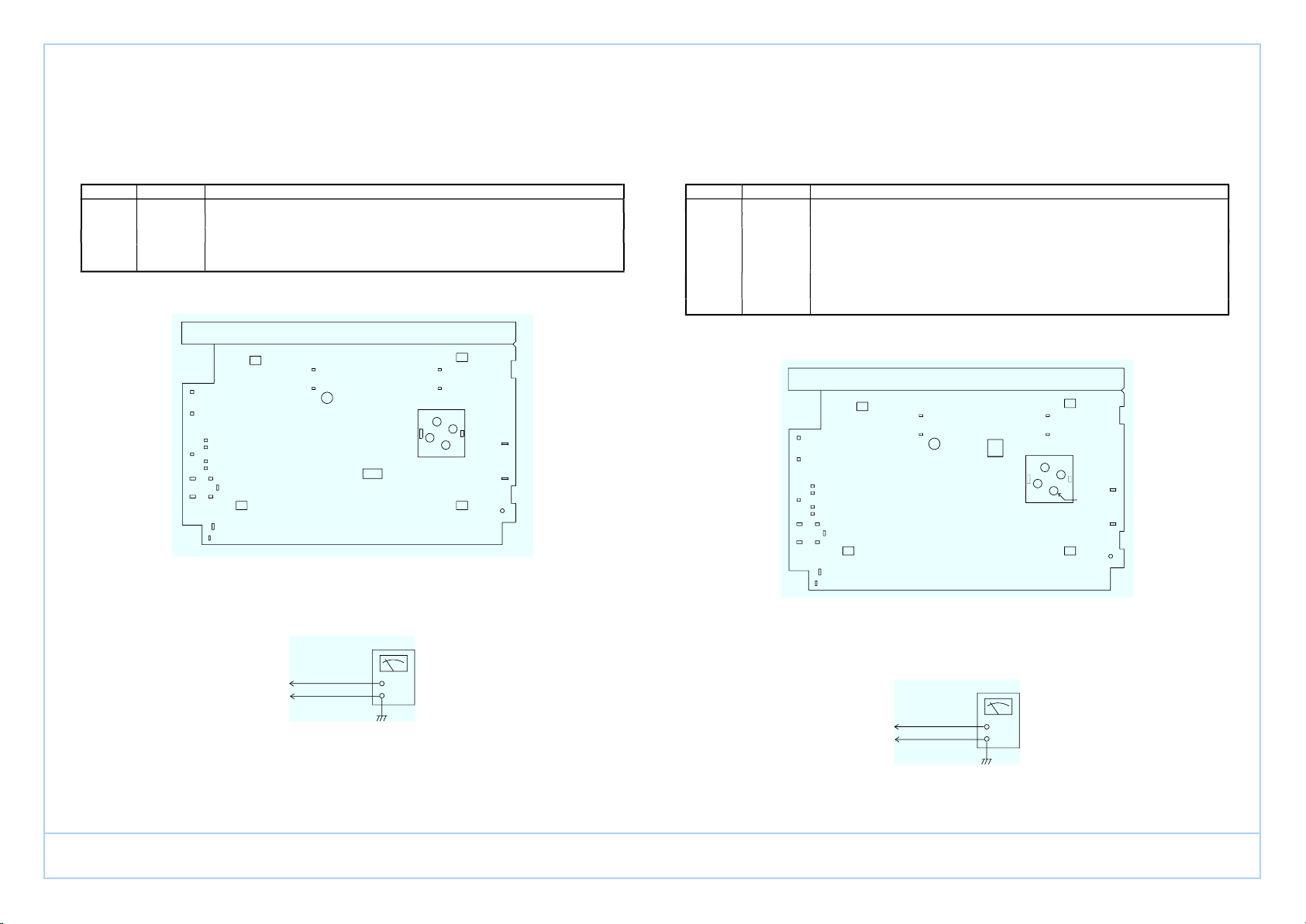
(3) ALIGNMENT FOR AM IF
a. Required Instruments
AM RF Signal Generator
SSVM
b. Alignment Procedure
Mode Adjustment Procedure
(1) Set the power switch to the ON position.
(2) Connect a SSVM to the TP2, TP3.
(3) Connect the AM signal generator to the loop antenna.
AM CF 1
(4) Set the signal generator to 460 kHz, with 30% modulation. Set the tuning gang
fully closed, and adjust CF1 for a maximum reading on the SSVM.
c. Instrument Connection
CF1
Test Point TP2
Test Point TP3
SSVM
(4) ALIGNMENT FOR AM FREQUENCY RANGE
a. Required Instruments
AM RF Signal Generator
SSVM
b. Alignment Procedure
Mode Adjustment Procedure
(1) Set the power switch to the ON position.
(2) Connect a SSVM to the TP2, TP3.
(3) Connect a AM RF signal generator to the loop antenna.
(4) Set the signal generator to 516.5 kHz with 30% modulation. Set the tuning
gang fully closed, and adjust T2 for maximum reading on the SSVM.
(5) Set the signal generator to 1630 kHz. Set the tuning gang fully open and adjust
VC4 for a maximum reading on the SSVM.
MW
T2
VC4
(6) Repeat Steps 4 and 5 until the best sensitivity is obtained at both frequencies.
c. Instrument Connection
T2
VC4
Test Point TP2
Test Point TP3
SSVM
ǵ
YACHT BOY 50

(5) ALIGNMENT FOR AM SENSITIVITY
a. Required Instruments
AM RF Signal Generator
SSVM
b. Alignment Procedure
Mode Adjustment Procedure
(1) Set the power switch to ON position.
(2) Connect a SSVM to the TP2, TP3.
(3) Connect the AM RF signal generator to the loop antenna.
(4) Set the signal generator to 558 kHz, with 30% modulation. Set the tuning gang
fully closed and adjust L17 for a maximum reading on the SSVM.
(5) Set the signal generator to 1440 kHz. Set the tuning gang fully open and adjust
VC3 for a maximum reading on the SSVM.
MW
L17
VC3
(6) Repeat steps 4 and 5 until the best sensitivity is obtained at both frequencies.
c. Instrument Connection
L17
VC3
Test Point TP2
Test Point TP3
SSVM
(6) OSCILLATOR ALIGNMENT FOR REMAINDER OF SW BANDS
a. Required Instruments
AM RF Signal Generator
SSVM
b. Alignment Procedure
Mode Pr ocedure
(1) Set the power switch to ON position.
(2) Connect a SSVM to the TP2, TP3.
(3) Connect a signal generator with a 10pF dummy antenna. (TP1, TP4)
(4) Set the signal generator’s frequency as noted below (use 1kHz, 30% modulation).
49m
16m
(5) With the tuning gang fully closed, adjust the appropriate coils noted below for maximum
reading on the SSVM.
Mode
Generator Frequency
Adjustment
49m 5.8 MHz T4
41m 7.0 MHz T3
31m 9.3 MHz T6
25m 11.43 MHz T5
21m 13.43 MHz T7
19m 15 MHz T9
16m 17.32 MHz T1
c. Instrument Connection
T7
T5
T1
T6
T4
T3
T9
10
pF
Test Point TP4
Test Point TP1
Signal Generator
Test Point TP2
Test Point TP3
SSVM
ǵ
YACHT BOY 50
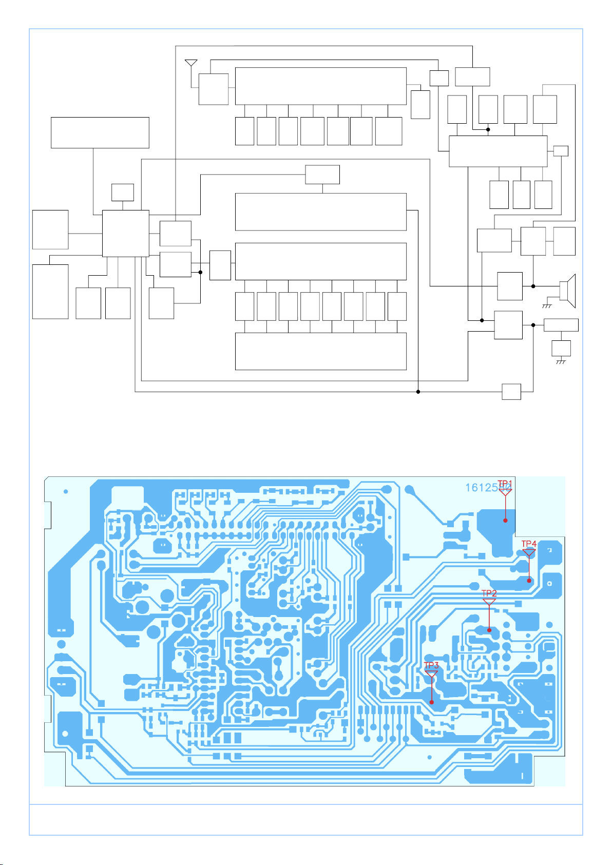
T4
L1
T1
Q1
TIME
LIGHT
AM
SW2
SW4
SW6 SW7
AM
IC2
OSC
Q4Buffer
Switch
Q6, Q7
HP
WORLD
KEY
SW103
LCD
Q106
Q107
OSC
T2
SW1
ANT
L2
OSC
T3
SW3
ANT
L6
OSC
T7T5
SW5
ANT
L5,L9
OSC OSC
T9
SW7
ANT
L11,L7
CF4
AMP
IF
FM
L16
IC3
HP
JACK
CF2
IF
FM
Det
FM
FM/AM
Switch
Batt
JACK
VR1
TC2
FM OSC
power
LED101
Q102
SW1
SW3 SW5SW1
SW1
L14,3
POWER
Q2, Q3
IC1 TA2111FN
SW2
ANT
Switch
AMP
FM OSC
Q101
AMP
IC101
TC9318FA
X101
OSC OSCOSC
T6
Q9
Buffer
R5, R7
BAND Det
SW2 SW4 SW6
ANT ANT ANT
L4,10 L8,12
SW1
D1
SWITCH
Q5, Q6
SWITCH
AMP
BUZZ
TDA2822
CF3
AM
CF1
T8
FM
ST/MO
Switch
L15
LIGHT
Q103
AM OSC
SW1
AM
OSC
TC1
DC JACK
ǵ
YACHT BOY 50
 Loading...