

Page 1

ǵ
DEUTSCH
ENGLISH
VIDEORECORDER
XERIA
GV 5153 HiFi
Page 2

CONTENTS
________________________________________________________
4 GV 5153 HiFi video recorder
Packing contents
Special features of your video recorder
5 Set-up and safety
6 Overview
The front of the video recorder
The back of the video recorder
The remote control
10 Connection and preparation
Insert batteries in the remote control
Connect the aerial and television
Connect aerial, television and GRUNDIG VCR-SAT module
Connect the aerial, television and GRUNDIG satellite receiver
Switch the video recorder on and off (energy-saving mode)
16 Tuning
Tuning the video recorder and the television
Automatic channel tuning (using ATS euro plus)
20 Playback
Basic playback functions
Additional playback functions
Continuous playback
25 Search functions
Zero setting
Finding recordings using the Video Index Search System (VISS)
26 Recording
Four recording options
The Video Programming System (VPS/PDC)
Immediate recording
Delayed recording by entering the ShowView number
Delayed recording by entering the data for the required television program
Checking, modifying or deleting recording information
Interrupting recording stand-by mode
Reactivating recording stand-by mode
36 Copying
Connection and preparation
Recording from external devices
2
Page 3

CONTENTS
_____________________________________________________________
38 Satellite receiver
Operation with a satellite receiver without a SAT control socket
Recording television programs from the satellite receiver
Recording – controlled by a satellite receiver
41 Using a decoder
Decoder operation with television stations from the antenna or the cable
system
Recording PAY TV programs
45 Audio playback
HiFi audio playback
Audio dubbing
47 Special settings
Sorting, deleting and renaming television stations
Re-tuning television channels
Skipping television stations
Setting new television stations from the antenna or the cable system
Tuning new television stations
Switching the station on the video recorder on and off
Setting new television stations from the VCR-SAT module
54 Setting the date and time
Automatically updating the time and date
Setting the time and date manually
55 Special features
Selecting special features in the »MODE« menu
Selecting special features in the »SERVICE« menu
58 Parental lock
59 Television remote control
60 Information
Rectifying minor problems
Technical data
GRUNDIG Service
ENGLISH
3
Page 4
GV 5153 HIFI VIDEORECORDER
P
ǵ
VIDEORECORDER
Tele Pilot 92 V
Digital FX
OSD
Clear
Timer/SV
SP/LP Timer on
Index
Dub
Audio Monitor
TV
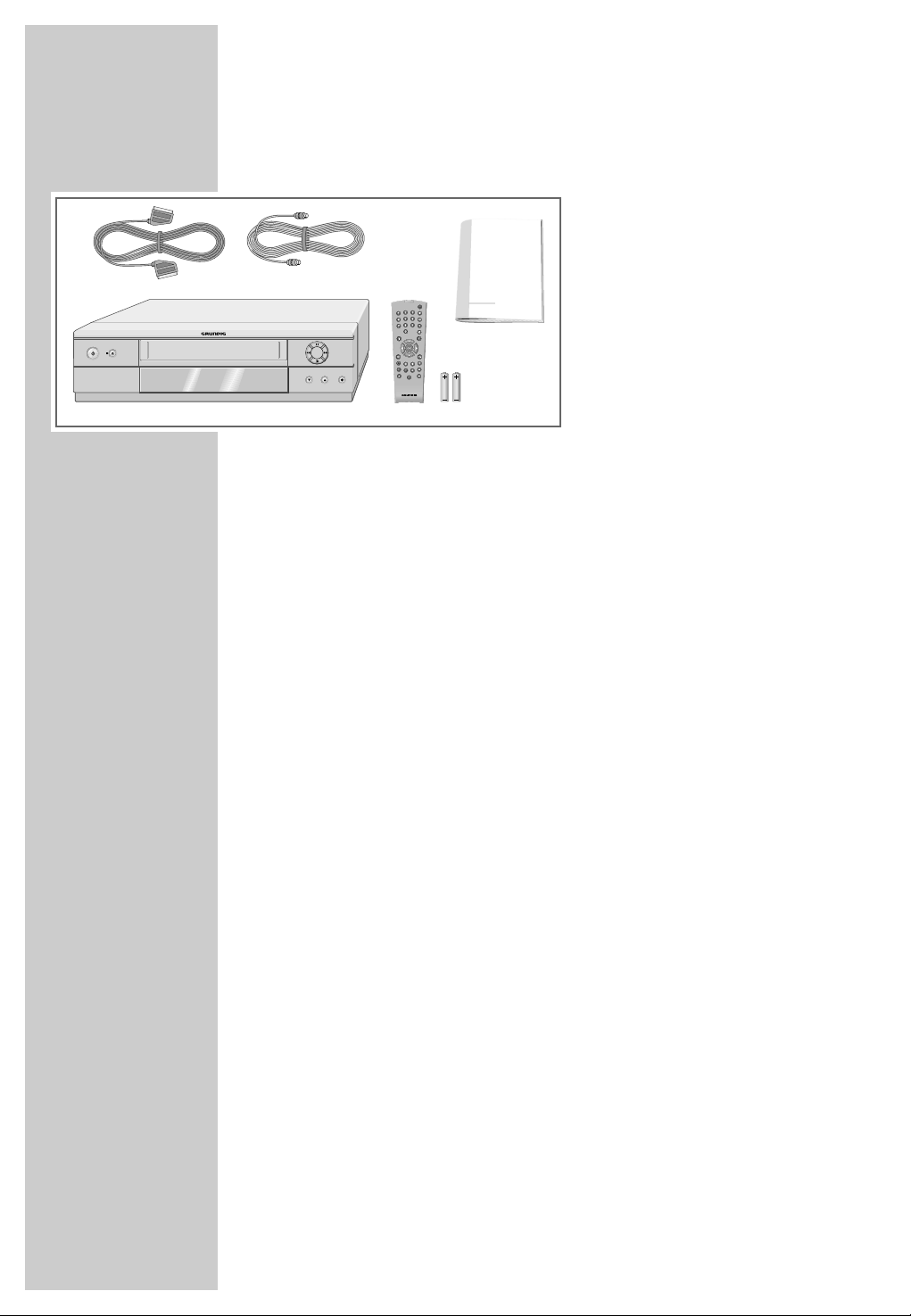
Packing contents
__________
2
1
3
4
2 EURO-AV cable
3 Antenna cable
4 Remote control
5 Operating manual
5
6 2 batteries, 1.5 V, mignon type
6
Special features of your video recorder
Four recording options
– Immediate recording, in which you select the required chan-
nel on the video recorder and start recording immediately.
– Delayed recording using the ShowView number.
– Delayed recording by entering the time and channel of the
programme you want to record (if you do not know the
ShowView number).
– Delayed recording by entering the data in the TIMER menu of
a Grundig television with the Megalogic function.
1 Video recorder GV 5153 HiFi
4
ShowView* recording
This function makes recording child’s play. Find the program in
your TV guide, enter the code number and the video recorder
is programmed automatically.
GRUNDIG Megalogic
Megalogic options:
– Receiving television stations in the same order from the televi-
sion set.
– Starting playback on the video recorder automatically selects
the video channel position on the television.
– The television station currently being shown on the television
screen is immediately recorded after the start of the recor-
ding.
– You can enter the data for a programme in the TIMER menu
of the television, and the television then controls the recording
of the video recorder.
* SHOWVIEW® is a registered trademark of the Gemstar Development
Corporation. The SHOWVIEW system was manufactured under licence
from the Gemstar Development Corporation.
Page 5
SET-UP AND SAFETY
P
°C
2h
°C
P
P
P
Krieg im Balkan
P
AV2 (DEC./EXT.)
AV1 (EURO AV)
This video recorder is designed to receive, record and play
back video and audio signals.
Any other use is expressly prohibited.
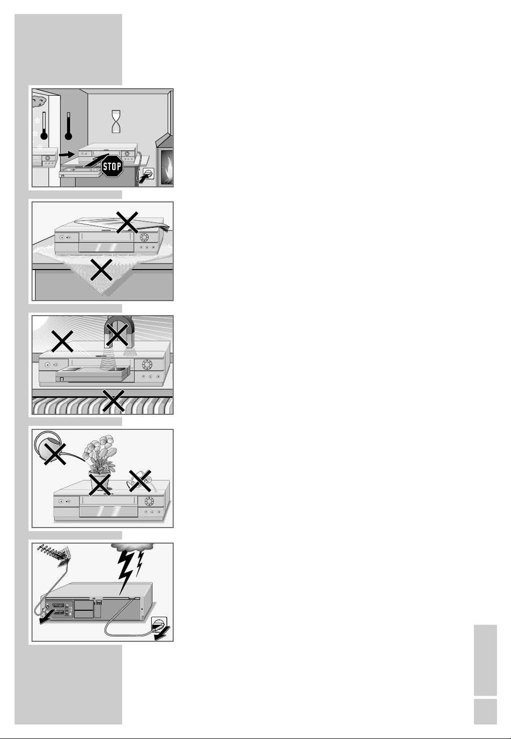
If the video recorder is subject to sudden changes in temperature, for example if it is brought in from the cold to a warm
room, connect it to the mains supply and let it stand for at least
two hours before you insert a video cassette.
The video recorder is designed for use in dry rooms. If you do
use it in the open, please ensure that it is protected from moisture, such as rain or water splashes. Do not expose the video
recorder or cassettes to moisture.
Place the video recorder on a hard, level surface. Do not place
any objects (newspapers, for example) on top of the video
recorder or any cloth or similar items underneath it.
Do not place the video recorder near heating units or in direct
sunlight, as this will impair cooling. Keep the video recorder
away from devices which generate magnetic fields, such as
loudspeakers.
___________________________________
Do not insert any foreign objects into the video tape compartment, as this may damage its precision mechanics.
Do not place any vessels such as vases on the video recorder
as they may spill liquid and present an electrical safety risk.
Thunderstorms present a danger to all electrical devices. Even
when the video recorder is switched off it can be damaged by
a lightning strike to the mains or antenna cable. Always
disconnect the mains and antenna plugs during a storm.
Do not open the video recorder casing under any circumstances. The manufacturer accepts no liability for damage resulting
from improper handling.
ENGLISH
5
Page 6
VIDEO IN L AUDIO IN R
OVERVIEW
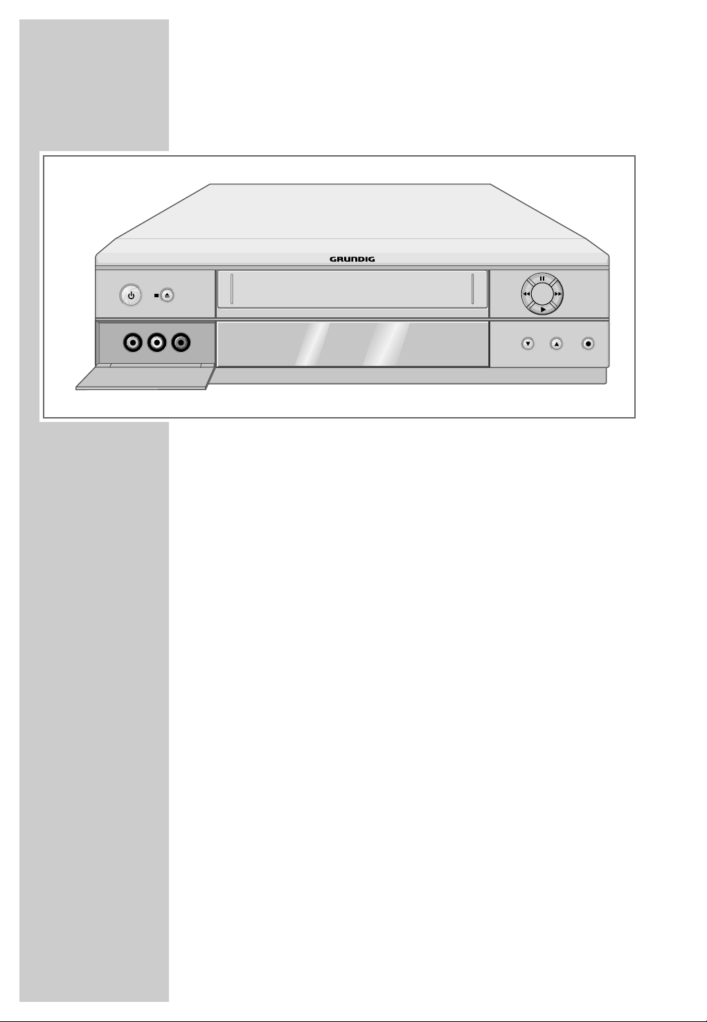
The front of the video recorder
_____________________________________________________________
P
A Switches the video recorder into and out of
stand-by mode (Low-power stand-by).
■ N Terminates all drive functions;
ejects the cassette.
VIDEO IN Camcorder video input (socket located behind
the cover panel).
L AUDIO IN R Left and right camcorder audio inputs (sockets
located behind the cover panel).
II Pause during recording, freeze-frame during
playback.
ľľ
ıı
ı
*
P
Ü Selects the next channel up.
P
● Starts recording.
During playback: reverse search;
when stopped: fast rewind.
During playback: forward search;
when stopped: fast forward.
Starts playback.
Selects the next channel down.
6
Page 7
OVERVIEW
AV2 (DEC./EXT.)
AV1 (EURO AV)
_____________________________________________________________
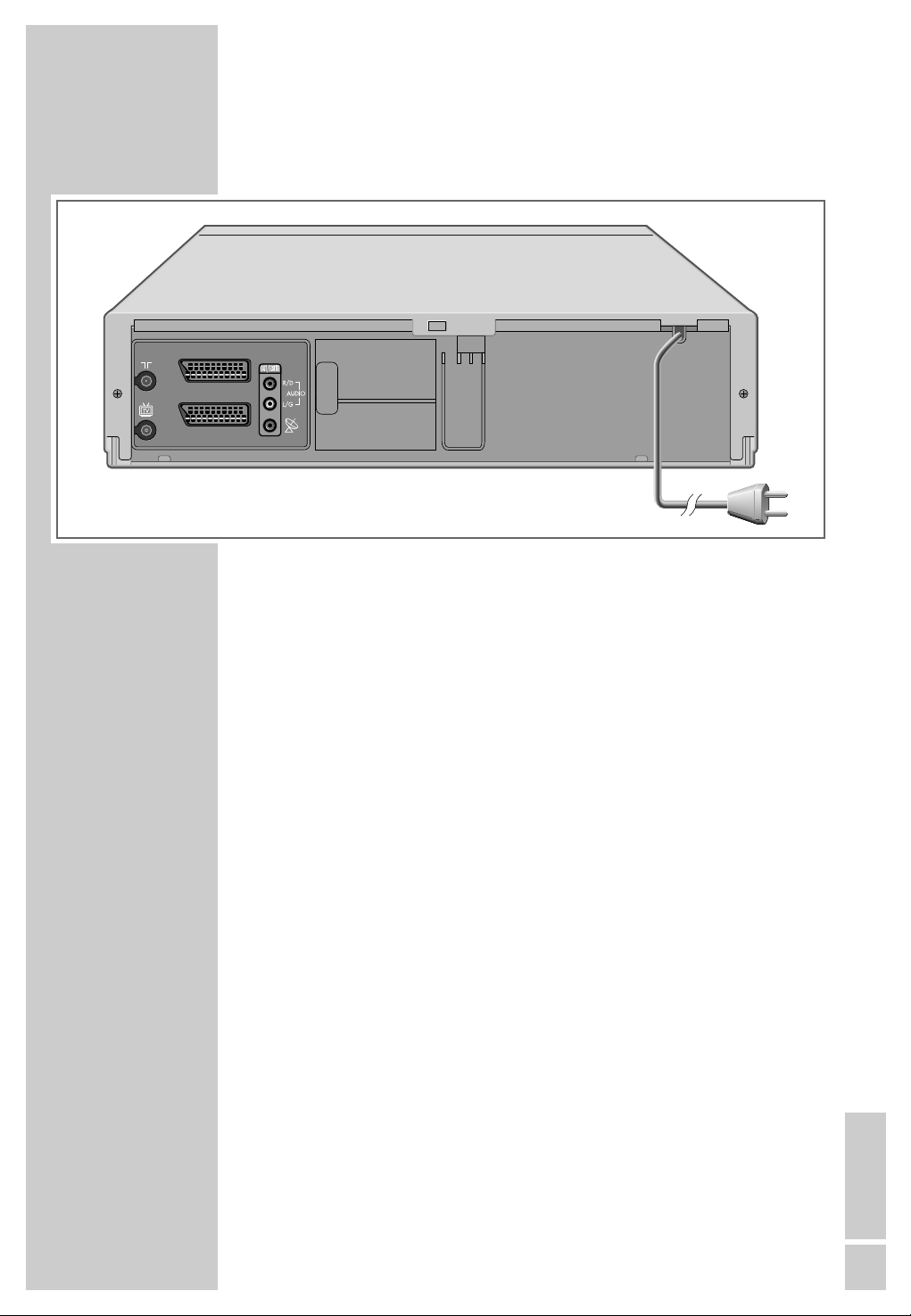
The back of the video recorder
Ä Antenna input socket
(from the roof antenna).
Ö Antenna socket
(to the television).
AV2 (DEC./EXT.) Euro-AV (Scart) socket
(to an external device).
AV1 (EURO AV) Euro-AV (Scart) socket
(to the television).
OUT/SORTIE Audio outputs to the HiFi system.
R/D AUDIO L/G
ʐ SAT control jack for the Grundig
VCR-SAT module and satellite
receiver.
Ü Mains cable for wall socket.
ENGLISH
7
Page 8
OVERVIEW
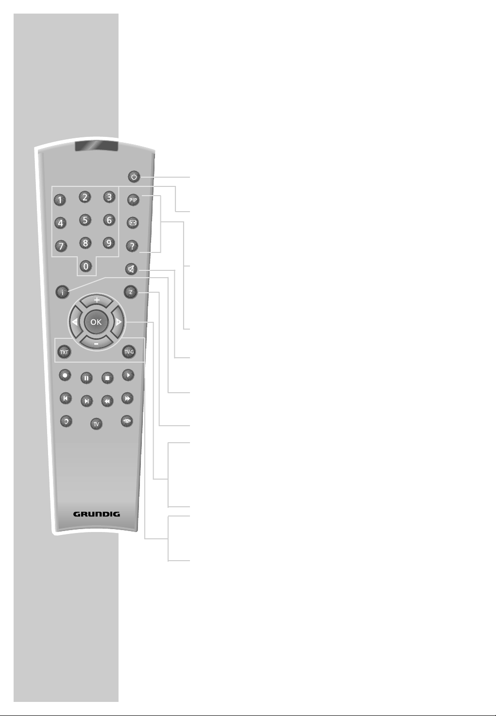
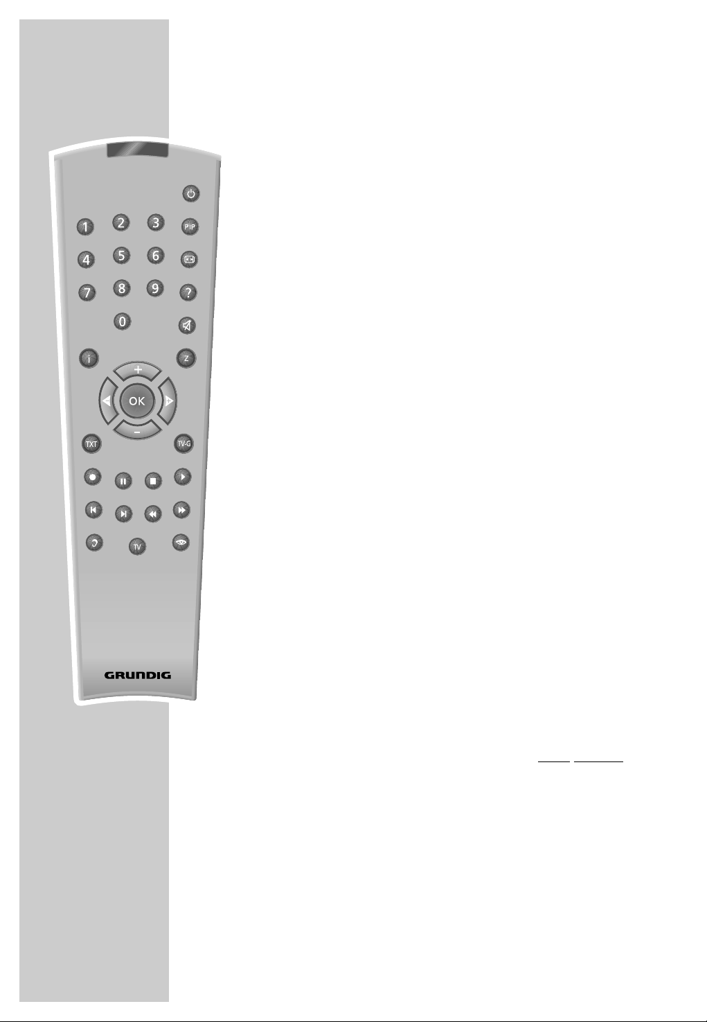
The remote control
The following section describes the most important features of
the remote control. See the relevant chapters in this manual for
information on how to operate the remote control.
Point the remote control at the video recorder.
_____________________________________________________________
SP/LP
Dub
Audio
Index
Digital FX
OSD
Clear
Timer/SV
Timer on
Monitor
Ǽ
Switches the video recorder in and out of standby mode (Low-power stand-by).
1 ... 0 Switch the video recorder on from stand-by;
numeric keys for various inputs,
A I
«, »
A2
» 0 « selects channel positions »
« or
»CV«.
Digital FX Key has no function.
OSD Calls up the on-screen display with information
on functions and playing time.
Clear Deletes data, activates settings, sets the playing
time indicator to »
d Switches the loudspeakers to and out of mute
0:00:00
«.
mode.
i Switches between the main menu and the TV
image.
Timer/SV Activates ShowView recording.
+ – Select channels, »
+ « up, » – « down;
Select various menu functions.
8
Tele Pilot 92 V
OK Calls up, confirms and saves data.
® † Select various functions in the menus.
SP/LP Switches between long play and standard play
mode.
Timer on Press briefly to activate TIMER recording; hold
down to deactivate TIMER recording.
Page 9
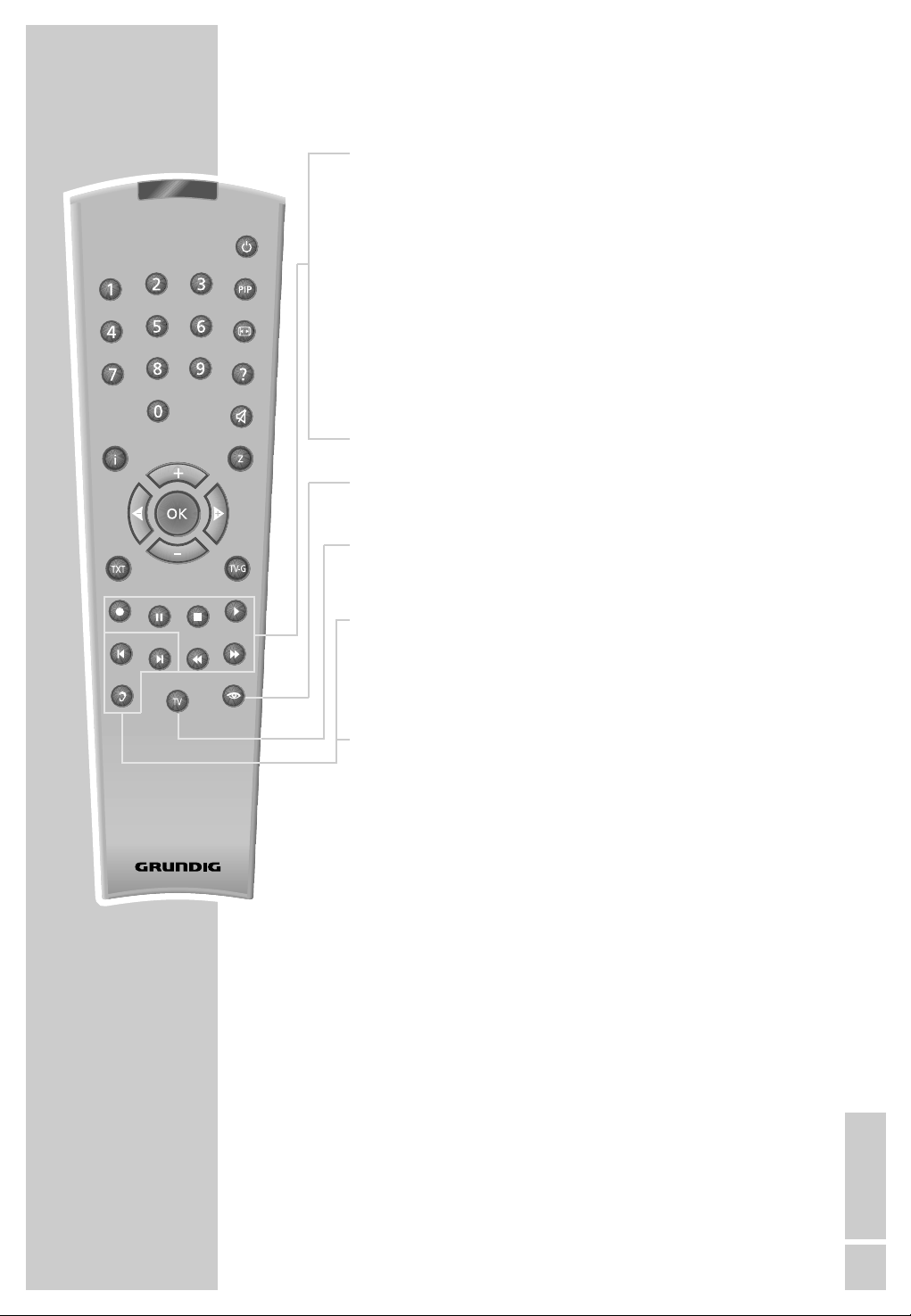
OVERVIEW
● Starts recording.
II Pause during recording, freeze-frame during play-
_____________________________________________________________
back.
SP/LP
Dub
Audio
Index
Digital FX
OSD
Clear
Timer/SV
Timer on
Monitor
■ Terminates all drive functions and switches the
video recorder to ”Stop”.
ı
Starts playback.
ľľ Reverse search during playback;
Fast rewind in ”Stop” mode.
ıı Forward frame search during playback;
Tape advance in ”Stop” mode.
Monitor Switches the screen display between the TV image
and the video recorder signal (Monitor mode).
TV Switches the remote control from video recorder
operation to television operation. The available
options are described starting on page 59.
Dub Selects the Dubbing function;
displays the menus on a blue background.
Index Activates the INDEX search functions.
Audio Selects the audio channel for recording and play-
back.
Tele Pilot 92 V
ENGLISH
9
Page 10

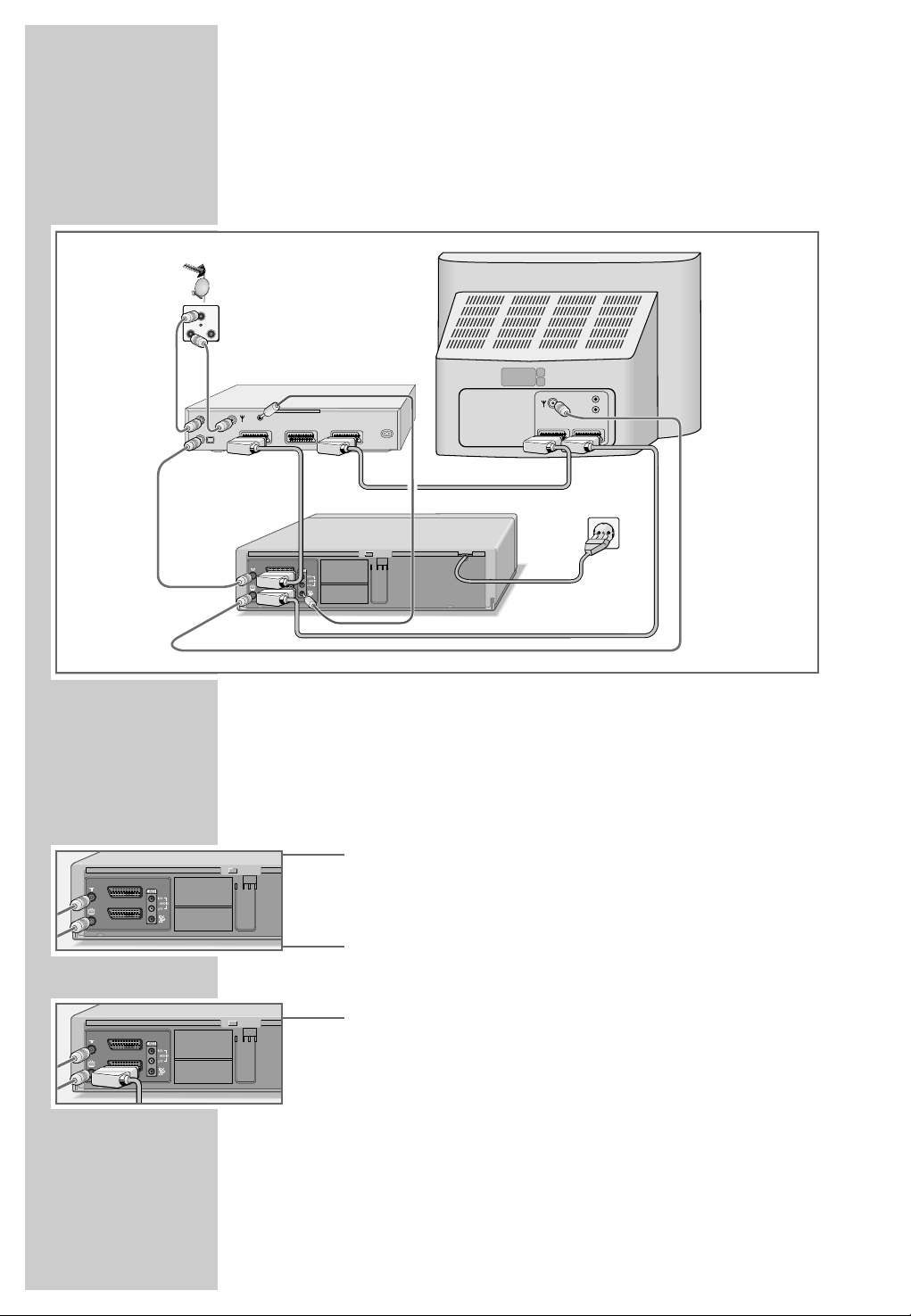
CONNECTION AND PREPARATION
Inserting batteries in the remote control
1 Open the battery compartment by pressing the tab and
removing the lid.
2 When inserting the batteries (mignon type, for example
LR 6 or AA, 2 x1,5 V), observe the polarity designation on
the battery compartment.
Note:
If the video recorder no longer reacts properly to remote
control commands the batteries may be flat. Always remove
flat batteries. No liability is accepted for damage resulting
from leaking batteries.
Environmental note
Batteries, including those which are heavy metal-free, may
not be disposed of with household waste. Please dispose of
used batteries in an environmentally sound way, for example at public collection points. Find out about the legal regulations which apply in your area.
___
Connection possibilities
In this section you will find examples for connecting:
– a video recorder and television set;
– a video recorder, television set and a Grundig VCR-SAT
module;
– a video recorder, television set and Grundig satellite receiver.
Instructions for connecting other devices, such as a decoder, a
HiFi system or a satellite receiver, without a control line can be
found starting on Page 36.
Notes:
If your television is equipped with Megalogic functions,
the video recorder and television set must be connected
with the EURO-AV cable provided; see step 3, page 11
and 12, or step 7, page 15.
If the video recorder is connected to a television set with
a 16:9 format, observe the setting in the section, ”Operation with a format 16:9 television” on page 56.
10
Page 11
CONNECTION AND PREPARATION
AV2 (DEC./EXT.)
AV1 (EURO AV)
AV2 (DEC./EXT.)
AV1 (EURO AV)
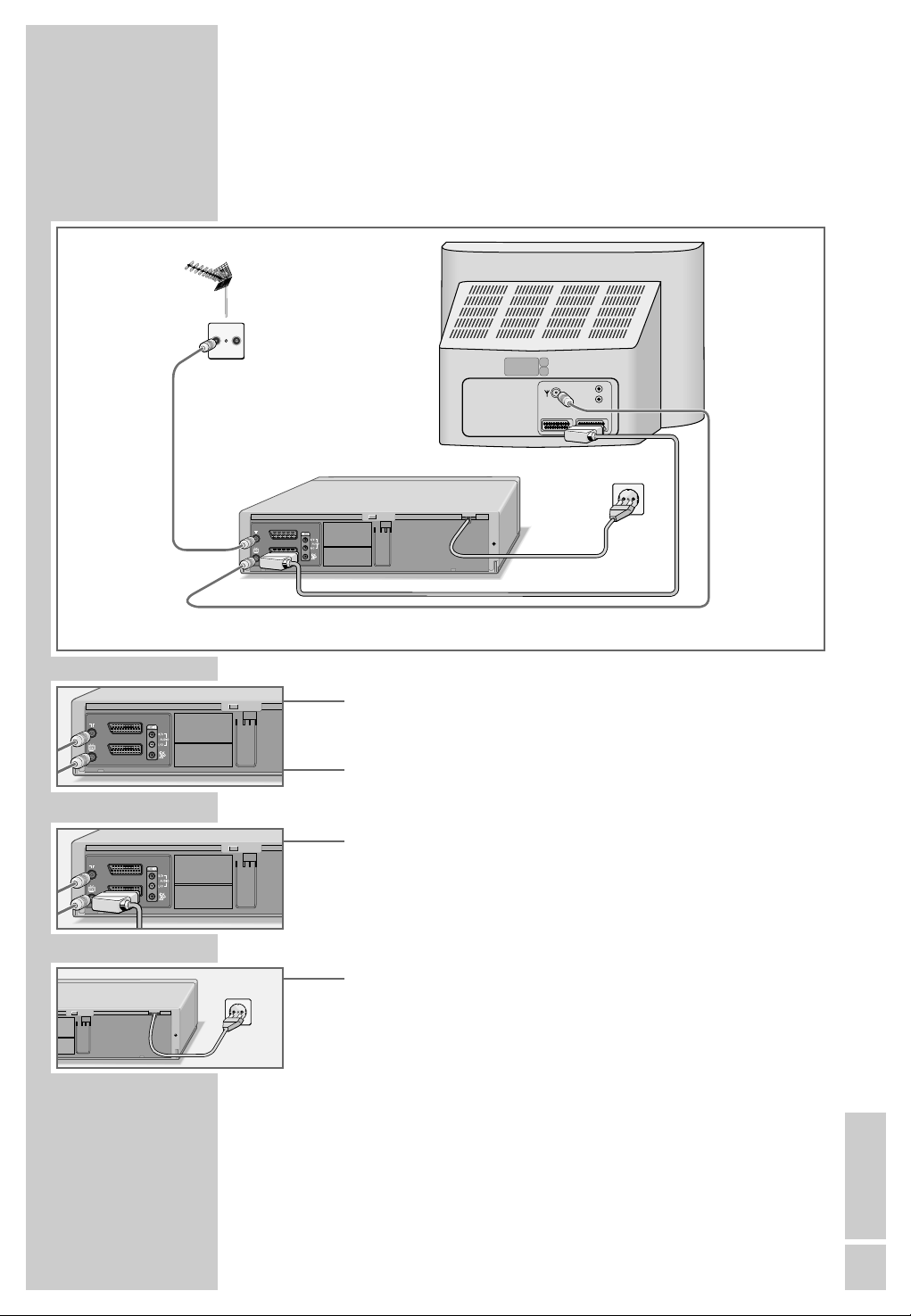
Connecting the antenna, television and
mains cable
TV R
L
R
AV1AV2
4
1
AV2 (DEC./EXT.)
AV1 (EURO AV)
3
___________________
2
1 Plug the roof antenna cable into the antenna socket »Ä«
on the video recorder.
2 Plug the antenna cable supplied into the »Ö« socket on
the video recorder and the antenna socket on the television.
3 Plug the EURO AV (Scart) cable supplied in the » AV 1
(EURO AV)« socket on the video recorder and the AV 1
socket on the television.
– Stereo sound can only be played back on a stereo televi-
sion set if this connection is used.
4 Plug the mains cable into the wall socket.
– The video recorder is now in stand-by mode.
Caution:
The only way to separate the video recorder from the mains
supply is to pull the plug.
ENGLISH
11
Page 12

CONNECTION AND PREPARATION
AV2 (DEC./EXT.)
AV1 (EURO AV)
AV2 (DEC./EXT.)
AV1 (EURO AV)
AV2 (DEC./EXT.)
AV1 (EURO AV)
Connecting the antenna, television set
and a GRUNDIG VCR-SAT module
___________________
1
SAT
R
TV
SAT-LINK
6
L
INPUT SAT
z
H
0
-6
0
5
V
30
2
z
H
M
0
5
1
V
-2
8
0
.
1
5
x
a
9
4/
1
m
A
5
,3
0
S
ER
V
O
C
VE
MO
E
VCR
RTS
DEC
A
R
T
-P
O
E
N
O
LIV
D
D
AR
Z
A
H
8
R
AV1AV2
4
5
7
AV2 (DEC./EXT.)
AV1 (EURO AV)
1 Plug the antenna cable of the roof antenna into the antenna
socket »Ä« on the video recorder.
2 Plug the antenna cable supplied into the »Ö« socket on
the video recorder and the antenna socket on the television
set.
23
12
3 Plug the EURO AV (Scart) cable supplied into the » AV 1
(EURO AV)« socket on the video recorder and the AV 1
socket on the television.
– Stereo sound can only be played back on a stereo televi-
sion set if this connection is used.
4 Connect the »AV2 (DEC./EXT.)« socket on the video
recorder to the »VCR« socket on the VCR-SAT module with
a standard Scart cable.
5 Connect the »ʐ « socket on the video recorder to the »SAT-
LINK« socket (control line) on the VCR-SAT module with a
standard Scart cable.
12
7
6 Plug the satellite antenna cable into the corresponding
antenna socket (INPUT-SAT) on the VCR-SAT module.
Page 13
CONNECTION AND PREPARATION
230 V 50-60 Hz
IN
P
U
T
S
A
T
VCR
DEC
950-2150 MHz
14/18 V
0,35 A max.
D
O
N
O
T
R
E
M
O
V
E
C
O
V
ER
S
H
A
Z
A
R
D
LI
V
E
-P
A
R
TS
SAT-LINK
Note:
The »AV2 (DEC./EXT.)« socket can also be used for con-
necting a PAY TV decoder.
If a VCR-SAT module is installed in this socket, connect the
PAY TV decoder to the »DEC« socket of the VCR-SAT module.
In this case, the decoder can only be used for television stations supplied by the VCR-SAT module.
7 Insert the power cord plug in the socket.
– The video recorder is now in standby mode.
8 Connect the VCR-SAT module to the mains supply.
Caution:
The only way to disconnect the video recorder and the VCRSAT module from the mains is to pull the plug.
___________________
ENGLISH
13
Page 14
CONNECTION AND PREPARATION
AV2 (DEC./EXT.)
AV1 (EURO AV)
AV2 (DEC./EXT.)
AV1 (EURO AV)
Connecting the antenna, television set
and a GRUNDIG satellite receiver
SAT
TV R
___________________
12
INPUT-SAT
TV
3
6
VIDEO CONTROL
EURO AV VCR EURO AV DECODER EURO AV TV
5
AV2 (DEC./EXT.)
AV1 (EURO AV)
L
220-240 V
~
50-60 Hz
R
AV1AV2
8
9
7
1 Plug the satellite antenna cable into the corresponding
antenna socket (INPUT-SAT) on the satellite receiver.
2 Plug the roof antenna cable (TV) into the corresponding
antenna socket (É) on the satellite receiver.
3 Plug the antenna cable supplied into the »Ä« socket on
the video recorder and the corresponding socket (TV) on the
satellite receiver.
4
14
4 Plug a standard antenna cable into the »Ö« socket on the
video recorder and the antenna socket on the television set.
5 Plug a standard Scart cable into the »AV2 (DEC./EXT.)«
socket on the video recorder and the »VCR« socket on the
satellite receiver.
Note:
The »AV2 (DEC./EXT.)« socket can also be used for connecting a PAY TV decoder.
If a VCR-SAT module is installed in this socket, connect the
PAY TV decoder to the decoder socket of the satellite receiver.
Page 15
CONNECTION AND PREPARATION
AV2 (DEC./EXT.)
AV1 (EURO AV)
6 Plug a standard cinch cable into the »ʐ « socket on the
video recorder and the »VIDEO CONTROL« socket (control
line) on the satellite receiver.
7 Plug the EURO AV (Scart) cable supplied in the » AV 1
(EURO AV)« socket on the video recorder and the AV 1
socket on the television.
– This connection provides for better picture and sound
quality during playback.
– Stereo sound can only be played back on a stereo televi-
sion set if this connection is used.
8 Plug a standard Scart cable in the »TV« socket on the satel-
lite receiver and the AV 2 socket on the television.
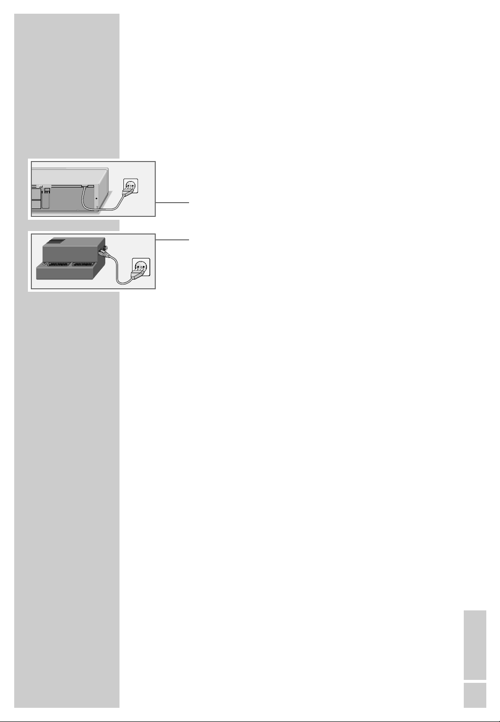
9 Insert the power cord plug in the socket.
– The video recorder is now in standby mode.
10
Connect the satellite receiver to the mains supply.
___________________
Caution:
The only way to disconnect the video recorder from the
mains supply is to pull the plug.
Switching the video recorder on and off
(power save mode)
1 Press »1 ... 0« to switch on the video recorder.
2 Press »
– The video recorder is now in stand-by mode and the
display shows the current time.
3 Press »
– The video recorder is now switched off, the time is no lon-
ger visible in the display and the green indicator »
illuminated. The power consumption is now less than
3 Watts.
Note:
You cannot switch off the video recorder if you have set it to
record programs later.
« to switch to stand-by.
Ǽ
« to switch off.
Ǽ
Ǽ
« is
ENGLISH
15
Page 16
TUNING
Tuning the video recorder and the
television
You do not need to do this if the video recorder and the television are connected via a EURO-AV (Scart) cable.
1 Switch on the television.
2 Select the »AV« channel position on the television set for
3 Tune the television to a free channel in the UHF band bet-
4 Store the free channel position on the television.
______________________________________________________________
recorder playback via the antenna cable.
ween channel 21 and channel 69. A free channel is one
which does not carry a signal from a television station (you
can only see and hear static).
– Many televisions display the channel number.
5 Press »
press and hold down »i«.
– The display on the video recorder reads something like
»
« to switch the video recorder to stand-by, then
Ǽ
CH 27
«.
6 Set the channel (in this example, channel 29) by pressing
» * P Ü « on the video recorder, until the test picture from
the video recorder appears on your television screen.
7 If the quality of the test picture is OK, press »i« to save the
setting.
– The video switches to stand-by.
Note:
If the quality of the test picture is unsatisfactory, or if the picture quality of other channels has deteriorated, then you
should find another free channel on the television and repeat the setting from steps 1 to 5.
You can switch off the station on the video recorder. Fore
more information see the ”Switching the station on the
video recorder on and off” on Page 51.
1616
Page 17

TUNING
Automatic channel tuning
(using ATS euro plus)
_________________________________________________________________
The video recorder has its own receiver unit. It can receive and
record from television stations independently of the television.
This means you must tune the television stations on the video
recorder.
During this setting the clock is automatically updated. However,
this is only possible if channel position 1 on the video recorder
is occupied by a station with teletext.
There are 99 channel positions available which can be assigned as required to television stations received via the antenna,
cable connection or satellite receiver.
If a VCR-SAT module or a satellite receiver with a SAT
control socket is connected to the video recorder, the stations
received through the VCR-SAT module or the satellite receiver
are saved in the station list, in addition to the stations received
through the antenna or the cable connection.
Note:
The VCR-SAT module or satellite receiver must be connected
before the settings are made, see Page 12 or 14.
Note on recording television programs with the
Megalogic function:
If the video recorder is connected to a television set with
Megalogic functions, this setting transfers the programs
stored in the television to the video recorder.
But the programs are not transferred if the »SAT CONTROL
ON« setting is selected in the »SAT RECEIVER« menu.
ENGLISH
ENGLISH
1717
17
Page 18
TUNING
AUTO INSTALLATION
PRESS OK KEY TO START.
AUTOMATISCHE EINSTELLUNG
ZUM START DIE OK-TASTE
DRÜCKEN.
_________________________________________________________________
Preparation
Switch on the television.
Select the channel position »AV« on the television for the video
recorder.
Automatic tuning
Note
Do not terminate the automatic search prematurely.
OK :EINGABE INFO:ENDE
SPRACHE
ENGLISH DANSK
DEUTSCH SVENSKA
FRANÇAIS SUOMI
ITALIANO ESPAÑOL
NEDERLANDS PORTUGUES
ɶʺ
<>
OK :EINGABE INFO:ENDE
ɶʺ
OK :ENTER INFO:EXIT
:WÄHLEN
COUNTRY
AI
BN
DK P
FIN E
DS
NL CH
F OTHERS
GB
<>
:SELECT
SAT RECEIVER
SAT CONTROL OFF
1 When the device is first operated, the menu »AUTO
INSTALLATION« appears automatically.
Hint:
If the »AUTO INSTALLATION« menu does not appear on
der
the screen press » * P« and » P Ü « on the video
recor
at the same time until you see the menu.
2 Press »OK« to begin the setting.
– The »SPRACHE« (LANGUAGE) menu appears.
3 Select the language using the »+ – ® †« buttons and
then press »OK« to confirm.
– The »COUNTRY« menu appears.
4 Select the country you are in using the » + – ® †« but-
tons.
Note:
If your country is not shown in the »COUNTRY« menu,
select »OTHERS«.
Press » OK « to confirm the country.
– A menu appears on the screen asking if all the cables
have been connected to the video. Check that they are
before continuing.
OK :ENTER INFO:EXIT
1818
<>
:CHANGE
5 Press »OK« to go the next setting.
– The »SAT RECEIVER« menu appears.
6 If no VCR-SAT module or satellite receiver with a SAT con-
trol socket is connected to the video recorder, select the
SAT CONTROL OFF« setting with »
»
continue the setting with step
7.
If a VCR-SAT module or a satellite receiver with a SAT control socket is connected, select the
setting with » ®« or » †«.
– A menu appears requesting that you connect the VCR-
SAT module or the satellite receiver to the video recorder.
®« or » †« and
»
SAT CONTROL ON
«
Page 19

TUNING
_________________________________________________________________
1 -----
AUTOMATIC SORTING
PLEASE WAIT
.0%
7 Start the automatic channel search by pressing »OK«.
– The video recorder searches all channels for television
stations, then sorts and saves them. The automatic search
can take several minutes.
– When the automatic search is completed the message
»AUTO SETUP COMPLETED!« appears on the screen
INFO:EXIT
along with the number of the output channel.
Note:
If the video recorder and the television are not
with a EURO-AV (Scart) cable, you need to repeat the setting on Page 16 and set the channel shown in the menu on
the television (for example »CH 21«).
8 Press »i« to terminate the setting.
Note:
Further settings, such as sorting, deleting and renaming
television stations, are described starting on page 47.
connected
ENGLISH
19
Page 20
PLAYBACK
Preparation
Switch on the television.
Select the channel position »AV« on the television for the video
recorder.
Digital FX
OSD
Clear
Timer/SV
Insert a recorded video tape into the compartment with the
window facing upwards until it is automatically drawn in.
– The video recorder display contains the following symbol:
» « (= tape symbol).
Note:
If you put a cassette with the protection tab removed into the
video recorder, playback starts automatically.
Basic playback functions
_________________________________________________________
ß
SP/LP
Dub
Audio
Index
Tele Pilot 92 V
Timer on
Monitor
1 Press »
« to start playback.
ı
– Information is displayed briefly on the television screen.
Note:
If the video recorder is connected to a television with
Megalogic functions, the television switches on after
playback is started from operating position stand-by
and automatically switches to program position »AV«.
2 To switch to freeze-frame/pause press » II«.
Press repeatedly to advance the picture frame by frame.
3 Press »
wards or reverse search.
ľľ
«
»
«
ıı
or
during playback to start a for-
Press several times to change the
playback speed.
4 To stop playback, press » ■ «.
5 To eject the cassette, press » ■
« on the video recorder.
ə
20
Page 21

PLAYBACK
Additional playback functions
Calling up information
_____________________________________________________________
OSD
OSD
1 Press the »OSD« button to call up information.
– Display on the television screen:
the channel position;
»USED« the elapsed playing time on the tape;
»REM« the remaining playing time;
»0:00:00« the tape counter in hours, minutes and
seconds;
the date and the time.
– You can call up this information successively on the video
recorder display by pressing »OK«.
– The tape counter can be set to »
»Clear«.
2 Switch off the information display by pressing »OSD«.
0:00:00
« by pressing
Fast forward/rewind
1 Press »■ « to stop the tape.
2 Press »ľľ« to rewind the tape or »
« to fast forward.
ıı
Double playback speed
1 Press »
« during playback.
ı
2 Press »
« again to return to normal playback speed.
ı
Slow motion
1 During freeze-frame (playback/pause) press and briefly
hold down »II«.
2 Press »®« or »†« to alter the slow-motion speed.
3 Press »
« to return to normal playback speed.
ı
Frame-by-frame playback
1 During freeze-frame (playback/pause) press »II« repea-
tedly.
2 Press »
« to return to normal playback speed.
ı
ENGLISH
212121
Page 22

PLAYBACK
Improving the quality of the freeze-frame
image
_____________________________________________________________
Ļ
Ļ
P
1 In freeze-frame mode (playback/pause) press » *
on the video
to adjust the image according to your taste.
2 Press »
Note:
The video stops the freeze-frame function after a certain
period of time.
recorder or »+« or »–« on the remote control
« to return to normal playback.
ı
Ü «
P
Eliminating picture disturbances
(adjusting the tracking position)
1 During playback, use »+ « and » –« to improve the picture
quality as you see it.
– Your setting is retained until you remove the cassette.
Ļ
Ļ
P
2 If you press » *
it switches to medium tracking.
der
Ü « simultaneously on the video recor-
P
Automatic picture improvement system
(ACC Plus)
22
Tapes recorded on other devices may have poor picture and
sound quality. This does not indicate a problem with your video
recorder.
1 During playback you can adjust the picture quality by pres-
sing »®« (softer) or »†« (sharper).
Clear
2 To return to the medium setting, hold down the »Clear«
button until you see the menu on the screen.
Playing back NTSC recordings
During playback of NTSC recordings the video recorder automatically switches over to this system.
Note:
A perfect freeze-frame is not possible during NTSC playback.
There may be some picture disturbances on NTSC long play
recordings.
Page 23

PLAYBACK
Selecting the audio track
You can select the audio signal you want to hear when playing
tapes recorded with stereo or two-channel broadcasts:
_____________________________________________________________
➔
AUDIO-MODE STEREO
■
ɶʺ
:SELECT
OK :ENTER INFO:EXIT
<>
:CHANGE
1 During playback, call up the menu by pressing »Audio«.
2 Select the audio signal using »®« or »†« and press
»OK« to confirm.
– On-screen display:
»STEREO« = stereo; »L« = left; »R« = right; »MONO« =
mono.
3 Press »i« to exit the Audio menu.
ENGLISH
232323
Page 24

PLAYBACK
Continuous playback
This function plays back the contents of the tape up to tape position »
rewinds the cassette to the start and begins playback again.
Activating continuous playback
1 Press »ı « to start playback and » OSD« to see the tape
2 At the required position on the tape, press » Clear« to
3 Press »i« to open the main menu.
_____________________________________________________________
0:00:00
«. At that point, the video recorder automatically
counter.
reset the tape counter to »
0:00:00
«.
– The main menu appears.
:SELECT
SERVICE
<>
:CHANGE
PIN8-CONTROL OFF
CHILD-LOCK - - - - TAPE-LENGTH E180
➔
CONTINUOUS-PLAY OFF
■
RF-CHANNEL AC21
ATS-RESTART AOFF
DEALER-MENU - - - -
ɶʺ
OK :ENTER INFO:EXIT
4 Select the » SERVICE« line using »+« or » –« and then
press » OK « to confirm.
– The » SERVICE« menu appears.
5 Select the » CONTINUOS-PLAY« line using »+ « or » –«.
6 Press »®« or »†« to activate continuous playback
(display » ON«) and press » OK « to confirm.
– The video recorder automatically rewinds the tape to the
beginning and starts playback there. The buttons on the
device and the remote control (except the »i« button) are
disabled during continuous playback.
Deactivating continuous playback
1 Open up the » SERVICE« menu by pressing the »i« button.
2 Press »®« or »†« to deactivate continuous playback
(display » OFF«) and press » OK « to confirm.
24
Page 25

SEARCH FUNCTIONS
Zero setting
With this search system the video recorder can automatically
rewind to position »
1 Press »ı « to start playback.
2 Press » OSD« to select the tape counter.
3 Press »Clear« at the required point on the tape to set the
tape counter to »
4 To rewind to the zero position on the tape, press » Index«
during playback and then press » 0«.
– The video recorder rewinds the tape to the zero position
and then resumes playback.
Finding recordings using the Video
0:00:00
0:00:00
« on the tape.
«.
__________________________________
Index Search System (VISS)
With this search system you can quickly find the exact beginning of each recording you make. The necessary ”markers”
are automatically set each time you make a recording.
1 Press »Index«.
2 Select the desired ”bookmark” (point on the tape) with
»
« or »
ľľ
– Display: » INDEX SEARCH«The video recorder automati-
cally winds the tape to the selected point on the tape and
begins playback there;
or
press »
– Display: » INTRO-SCAN«.
ľľ
The video recorder winds the tape to the next ”bookmark”, switches briefly to playback mode, then winds the
tape to the next ”bookmark”.
ıı
« or »
«.
ıı
« once.
ENGLISH
ENGLISH
252525
25
Page 26

RECORDING
Four recording options:
Your video recorder provides you with four different options for
recording television programmes:
1 Immediate recording, in which you select the required sta-
tion on the video recorder and start recording immediately.
2 Delayed recording using ShowView numbers.
3 Delayed recording by entering the date, time and channel
of the programme you want to record if you do not know
the ShowView number.
4 Delayed recording by entering the data in the TIMER menu
of a Grundig television with the Megalogic function.
You can find information on using this option in the operating manual that came with your television set.
_____________________________________________________
With recording options 2 and 3 you can set the video to
record up to six programmes as much as a year in advance,
or record programmes at the same time every day or week.
The Video Programming System
(VPS/PDC)
This system guarantees successful recording when you set the
VCR in advance to tape a broadcast.
Many television stations broadcast a supplementary signal
(VPS/PDC signal) which indicates the start and duration of
each individual television programme. When you are programming the video recorder, it is therefore important to enter
the times when it is to switch on and off to the nearest minute.
If television programmes are changed or re-scheduled, then
special VPS/PDC times which must be entered instead of the
scheduled times are detailed in the television guides.
In the case of television stations which do not transmit a
VPS/PDC signal, recording depends solely on the times set for
the video recorder to switch on and off. This is regardless of
whether you confirm or delete the VPS/PDC signal when you
program the video recorder.
If you use a rotating dish and enter the recording data for television programs from different satellite positions, you can only
program the VPS signal for the television program of one satellite position, otherwise the motor of the rotating satellite dish
may become overloaded.
2626
Page 27

RECORDING
Immediate recording
Preparation
Switch on the television.
Select the channel position »AV« on the television for the video
Digital FX
OSD
Clear
recorder.
Insert a video cassette with sufficient playing time and the tab
intact (i.e. not erase-protected) into the compartment until it is
automatically drawn in.
– The video recorder display contains the following symbol:
» « (tape symbol).
__________________________________________________________
ß
SP/LP
Dub
Audio
Index
Tele Pilot 92 V
Timer/SV
Timer on
Monitor
Operation
1 If necessary select long play mode by pressing » SP/LP«.
– The video recorder display reads »LP«.
2 Before recording select the television station by pressing
»+ « » –«or
3 To start recording, press »●« and briefly hold it down.
Note:
If the video recorder is connected to a television set with
Megalogic functions, the television programme appearing
on the screen can be recorded by pressing »●«. It is not
necessary to select the channel position on the video recorder.
4 Press »II« to temporarily interrupt recording.
Note:
During a pause in recording you can switch to another television channel.
»* P Ü «or» 0 ... 9«.
5 To finish recording, press » ■ «.
6 To rewind the tape, press » ľľ «, to fast forward press
»
«.
ıı
7 To eject the cassette, press » ■
« on the video recorder.
ə
ENGLISH
ENGLISH
272727
27
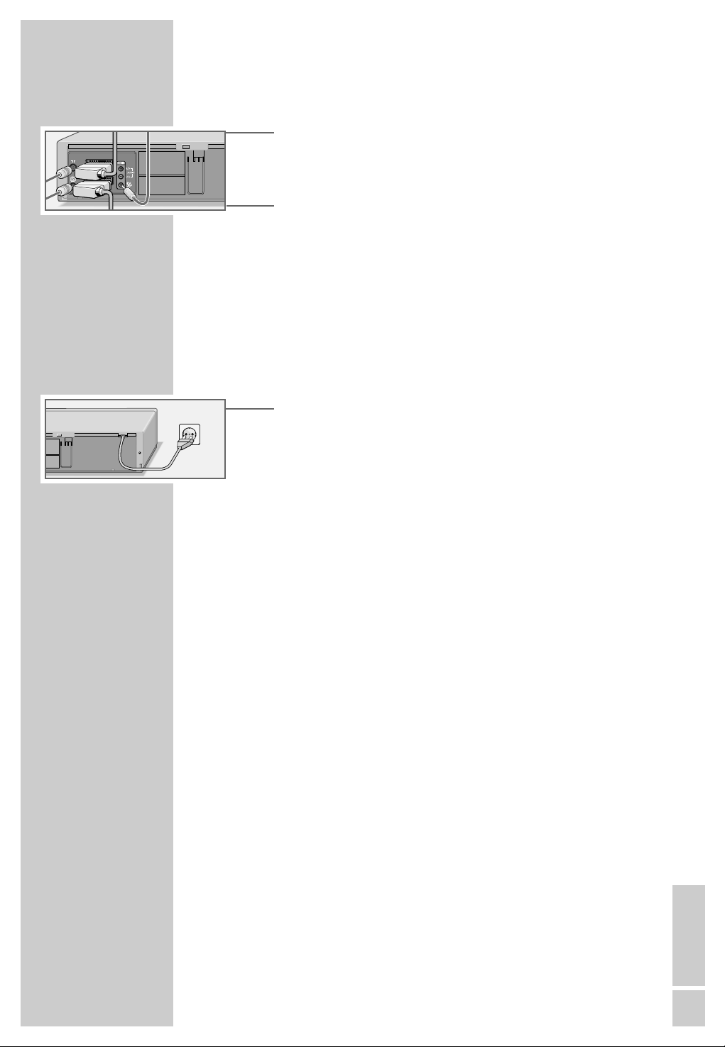
Page 28

RECORDING
Entering the recording stop time
1 During the recording, press »●« to advance the recording
stop time in 30 minute increments;
or
press »+ « or »–« to enter the stop time to the nearest minute.
– The stop time is only displayed on the television screen.
– The video recorder shows the TIMER display » Ȅ«, and
shuts off when this time is reached.
Seamless compilation of recordings
(Assemble)
This function enables you to make recordings without periods
of interference between them.
__________________________________________________________
1 During playback, locate the end of the scene after which the
new recording should start and press »II« at this position
on the tape.
2 Press »● « to pause the video recorder.
3 Select the television channel using »+ « » –«or»* P Ü «
or enter »0 ... 9« and start the new recording by pressing
»● «.
2828
Page 29

➔
SHOWVIEW NO.: –
■
MODE: ONCE
RECORDING
Delayed recording by entering the
ShowView number
Notes:
The time and date on the video recorder must be accurate.
The ShowView numbers for television programmes are prin-
ted in the TV guides.
If all the TIMER positions are occupied you must delete one.
To do this, see the section entitled ”Deleting recording data”
on Page 35.
Preparation
Switch on the television and select the channel position »AV«
on the television for the video recorder.
Insert a video cassette with sufficient playing time and the
erase-protection tab intact into the compartment until it is automatically drawn in.
If the video recorder is on recording stand-by, press and hold
down the » Timer on« button.
__________________________________________________________
0-9 :DATA
INFO:EXIT
➔
SHOWVIEW NO.: 12555-
■
MODE: ONCE
ɶʺ
:SELECT
OK :ENTER INFO:EXIT
SHOWVIEW NO.: 12555
MODE: ONCE
DATE PR START STOP
01/ 05 -- 12:00 12:30 S
PR : -----
<>
:SELECT
0-9 :DATA
<>
:CHANGE
0-9 :DATA
ɶʺ
:CHANGE
INFO :EXIT
Example
1 Press » Timer/SV « to begin the setting.
– The »SHOWVIEW« menu appears.
2 Enter the ShowView number for the programme you want
to record using » 0 ... 9«.
Notes:
If you type in an incorrect number, you can delete the
ShowView number space by space by pressing »®«.
If you want to record the programme at the same time every
day or week, select »MODE« by pressing » –« and select
the function you require (ONCE WEEKLY DAILY) with
®« or »†«.
»
The ”daily” function cannot be used for recording on Saturdays or Sundays.
3 Press »OK « to confirm the ShowView number.
– The current recording data appears on the screen.
Note:
*
The first time you set the recorder to tape a programme on
a television channel » PR« is highlighted in the menu.
The video recorder must first ”learn” the channel positions
on which the individual stations have been stored.
Enter the two-digit channel number (e.g. »03«) using the
» 0 ... 9 « buttons.
You no longer need to select the channel when you subsequently record broadcasts on that station.
ENGLISH
ENGLISH
292929
29
Page 30

SHOWVIEW NO.: 12555
MODE: ONCE
DATE PR START STOP
01/05
PR :
<>
OK :ENTER INFO:EXIT
CV
:SELECT
12:00 12:30 S
0-9 :DATA
ɶʺ
:CHANGE
RECORDING
4 If you are recording the audio/video signal from an exter-
nal device rather than one of the television stations, select
»AV1«, »AV2«, or » CV« as the channel by pressing »+«
or »– «.
*
Recording from a satellite receiver:
If a television station from an installed satellite receiver
without a SAT control line is programmed, select the channel position »AV 2« with »+ « or »–«. The satellite receiver
must be switched on at the selected recording time and for
the duration of the TIMER recording.
(This is not necessary for the Grundig VCR-SAT module or
for many Grundig satellite recievers with a SAT control
line.)
__________________________________________________________
SHOWVIEW NO.: 12555
MODE: ONCE
DATE PR START STOP
01/05 03 12:00 12:30 S
SP/LP/A : TAPE SPEED
<>
:SELECT
OK :ENTER INFO:EXIT
SHOWVIEW NO.: 12555
MODE: ONCE
DATE PR START STOP
01/05 03 12:00 12:30 S
VPS/PDC*: ON – : OFF
<>
:SELECT
OK :ENTER INFO:EXIT
➔
SHOWVIEW NO.: –
■
MODE: ONCE
ɶʺ
ɶʺ
:CHANGE
:CHANGE
5 Select the tape speed if necessary by pressing »†« to
select »S« and then set it using »+« or » –«:
*
»S« is standard play mode;
»L « is long play mode;
»A« is automatic mode.
– In automatic mode the video recorder compares the remai-
ning playing time with the length set for the recording and
automatically selects long play mode if necessary.
Note:
Automatic mode is not available for TIMER recordings with
VPS/PDC.
*
6 Switch off VPS/PDC (if it is not required) by pressing »†«
to select »*« and then »+ « or » –« to switch off VPS.
– »*« in the display denotes VPS recording.
7 Save the recording data by pressing » OK «.
– The »SHOWVIEW« menu reappears on the screen.
8 For further recordings, repeat the procedure from step 2 or
terminate the function by pressing » i«.
3030
0-9 :DATA
INFO:EXIT
9 Press » Timer on« to switch the VCR to recording stand-by.
– The video recorder display now shows the time and the
TIMER symbol »
ding stand-by mode.
Ȅ«. The video recorder is now in recor-
Page 31

RECORDING
Delayed recording by entering the data
for the required television program
Employ this method of recording if you do not know the ShowView numbers for the television programs.
Notes:
The time and date on the video recorder must be accurate.
If all the TIMER positions are occupied you must delete one.
To do this, see the section entitled ”Deleting recording data”
on Page 35.
Operation can be interrupted at any time using the »i«
button.
Preparation
Switch on the television.
Select the channel position »AV« on the television for the video
recorder.
Insert a video cassette with sufficient playing time and the tab
intact (i.e. not erase-protected) into the compartment until it is
automatically drawn in.
If the video recorder is on recording stand-by, press and hold
down the » Timer on« button.
__________________________________________________________
DATE PR START STOP
--/ --- -- --:-- --:-- S
--/--- -- --:-- --:-- --
--/--- -- --:-- --:-- --
--/--- -- --:-- --:-- --
--/--- -- --:-- --:-- --
--/--- -- --:-- --:-- --
OK :ENTER INFO:EXIT
Example
Note:
Enter the date, channel, start and finish time by pressing
»+« or » –«. Press »†« to jump to the next entry.
The example describes how to enter the data using the
numerical buttons » 0… 9«.
1 Press »i« to begin the setting.
*
– The main menu appears.
2 Highlight the » TIMER« line by pressing » OK«.
– The »TIMER« menu appears.
3 Press » OK« to begin entering data.
– The current date is displayed.
ENGLISH
ENGLISH
313131
31
Page 32

RECORDING
__________________________________________________________
DATE PR START STOP
01/02- 02 --:-- --:-- S
--/--- -- --:-- --:-- --
--/--- -- --:-- --:-- --
--/--- -- --:-- --:-- --
--/--- -- --:-- --:-- --
--/--- -- --:-- --:-- -DATE: DAY/MONTH
0-9 :DATA
<>
:SELECT
DATE PR START STOP
/02 02 --:-- --:-- S
01
--/--- -- --:-- --:-- --
--/--- -- --:-- --:-- --
--/--- -- --:-- --:-- --
--/--- -- --:-- --:-- --
--/--- -- --:-- --:-- -PR :ZDF
<>
:SELECT
DATE PR START STOP
01/ 02 02 19: -- --:-- S
--/--- -- --:-- --:-- --
--/--- -- --:-- --:-- --
--/--- -- --:-- --:-- --
--/--- -- --:-- --:-- --
--/--- -- --:-- --:-- --
ɶʺ
:CHANGE
INFO :EXIT
0-9 :DATA
ɶʺ
:CHANGE
INFO :EXIT
4 Confirm the date (DATE) by pressing »†«, or
*
enter the desired date in four digits with » 0 ... 9 «.
5 If you want to record the programme daily or weekly, press
»+« or » –« to select »D« (daily) or »W« (weekly). » – « in
the display means that it is a once-only recording.
Press »†« to confirm the setting.
Note:
You cannot
days and Sundays.
*
6 Enter the two-digit channel number (PR) using the
» 0 ... 9 « buttons.
Note:
If you are recording the audio/video signal from an external device rather than one of the television stations select
»AV1«, »AV2«, or » CV« as the channel by pressing »+«
or »– «.
Recording from a satellite receiver:
If a television station from an installed satellite receiver
without
nel position »AV 2« with »+ « or »–«. The satellite receiver
*
must be switched on at the selected recording time and for
the duration of the TIMER recording.
(This is not necessary for the Grundig VCR-SAT module or for
many Grundig satellite recievers with a SAT control line.)
use the ”daily” function for recording on Satur-
a SAT control line is programmed, select the chan-
0-9 :DATA
<>
:SELECT
DATE PR START STOP
01/02- 02 19:30 20:15 S
--/--- -- --:-- --:-- --
--/--- -- --:-- --:-- --
--/--- -- --:-- --:-- --
--/--- -- --:-- --:-- --
--/--- -- --:-- --:-- -SP/LP/A: TAPE SPEED
<>
:SELECT
ɶʺ
INFO :EXIT
ɶʺ
INFO :EXIT
3232
:CHANGE
:CHANGE
7 Enter the time to start recording (START) as four digits with
» 0 ... 9 «.
8 Enter the time when the recording finishes (STOP) as four
digits with » 0…9«.
9 Set the tape speed using »+« or » –« if necessary:
*
»S« is standard play mode;
»L « is long play mode;
»A« is automatic mode.
– In automatic mode the video recorder compares the
remaining playing time with the length set for the
recording and automatically selects long play mode if
necessary.
Note:
Automatic mode is not available for TIMER recordings with
VPS/PDC.
Page 33

RECORDING
10 Switch off VPS/PDC (if it is not required) by pressing »†«
to select »*« and then »+« or » –« to switch off VPS.
– »*« in the display denotes VPS recording.
__________________________________________________________
DATE PR START STOP
/02- 02 19:30 20:15 S
01
/ --- -- --:-- --:-- S
--
--/--- -- --:-- --:-- --
--/--- -- --:-- --:-- --
--/--- -- --:-- --:-- --
--/--- -- --:-- --:-- --
ɶʺ
:SELECT
OK :ENTER INFO:EXIT
11Save the recording data by pressing » OK «.
*
– The »TIMER« menu is displayed on the screen.
*
12
For further recordings, repeat the procedure from step 3, or
terminate the function by pressing »i«.
13
Press » Timer on« to switch the VCR to recording stand-by.
– The video recorder display now shows the time and the
TIMER symbol » Ȅ«. The video recorder is now in recording stand-by mode.
Checking, modifying or deleting
recording information
Preparation
Switch on the television.
Select the channel position »AV« on the television for the video
recorder.
MENU
ITIMER
MODE
INSTALL
SERVICE
ɶʺ
:SELECT
OK :ENTER INFO:EXIT
Calling up the TIMER menu
1 If the video recorder is in recording stand-by mode, press
and hold down » Timer on«.
2 Press » 1 ... 0« to switch on the video recorder.
3 Press »i« to open the main menu.
Note:
Select the function you require in the »TIMER« menu. For
information on using these functions see the following sections, each time starting from Step 1.
ENGLISH
ENGLISH
333333
33
Page 34

RECORDING
Checking recording data
__________________________________________________________
DATE PR START STOP
/02- 02 19:30 20:15 S
01
--/ --- -- --:-- --:-- S
--/--- -- --:-- --:-- --
--/--- -- --:-- --:-- --
--/--- -- --:-- --:-- --
--/--- -- --:-- --:-- --
ɶʺ
:SELECT
OK :ENTER INFO:EXIT
DATE PR START STOP
/02 02 19:45 20:15 S
01
--/--- -- --:-- --:-- --
--/--- -- --:-- --:-- --
--/--- -- --:-- --:-- --
--/--- -- --:-- --:-- --
--/--- -- --:-- --:-- --
1 Highlight the » TIMER« line by pressing » OK «.
*
*
– The »TIMER« menu appears and you can check the recor-
ding data.
2 Press »i« to quit the »TIMER« menu.
3 Press » Timer on« to switch the VCR to recording stand-by.
– The video recorder display now shows the time and the
TIMER symbol » Ȅ«. The VCR is in recording stand-by
mode.
Modifying recording data
1 Highlight the » TIMER« line by pressing » OK «.
– The »TIMER« menu appears.
2 Press »+« or » –« to select the required item in the TIMER
menu and then » OK « to highlight it.
– The selected TIMER position is moved to the last line of the
*
menu.
3 Select the required recording data using »®« or »†«
and edit it using »+«, » –« or » 1 ... 0«.
0-9 :DATA
<>
:SELECT
OK :ENTER INFO:EXIT
ɶʺ
:CHANGE
4 Press » OK « to save the recording data.
5 Press »i« to quit the »TIMER« menu.
6 Press » Timer on« to switch the VCR to recording stand-by.
– The video recorder display now shows the time and the
TIMER symbol » Ȅ«. The VCR is in recording stand-by
mode.
3434
Page 35

RECORDING
Deleting recording data
__________________________________________________________
DATE PR START STOP
02 02 19:30 20:15 S
/
01
01/02 04 21:00 22:00 S
--/ --- -- --:-- --:-- S
--/--- -- --:-- --:-- --
--/--- -- --:-- --:-- --
--/--- -- --:-- --:-- --
ɶʺ
:SELECT
OK :ENTER INFO:EXIT
1 Highlight the » TIMER« line by pressing » OK «.
*
– The »TIMER« menu appears.
*
*
2 Select the TIMER item in question with »+« or » –« and
press »Clear« to delete it.
3 Press »i« to quit the »TIMER« menu.
4 If several TIMER items have been programmed, press
» Timer on« to switch the VCR to recording stand-by.
– The video recorder display now shows the time and the
TIMER symbol » Ȅ«. The VCR is in recording stand-by
mode.
Interrupting recording stand-by mode
If you have set the VCR to record programs and want to use it
while it is in record stand-by mode.
1 Press and briefly hold down » Timer on«.
– The TIMER symbol » Ȅ« disappears.
2 Press » 1 ... 0« to switch on the video recorder.
3 Use the video recorder as required.
Note:
Five minutes before the TIMER recording starts you will see
the following message on the screen: »TIMER RECORDING
TO START SOON«.
You can hide this message by pressing »i«.
Reactivating recording stand-by mode
1 Insert a video cassette with enough playing time and the
erase-protection tab intact into the tape compartment, and
then press » Timer on«.
– The video recorder display now shows the time and the
TIMER symbol » Ȅ«. The VCR is in recording stand-by
mode.
ENGLISH
ENGLISH
353535
35
Page 36

COPYING...
... from another video recorder, a DVD player or a camcorder
Connection and preparation
______________________________________________________
AUDIO
L
L
O
I
U
N
T
R
R
AV2 (DEC./EXT.)
AV1 (EURO AV)
To the television
2 EXTERNAL / DEC. - AV 2
1 EXTERNAL / EURO - AV 1
ń
VIDEO IN L AUDIO IN R
VIDEO IN
LR
AUDIO IN
Connecting a camcorder
Connect the »L AUDIO IN R« (audio signal) and »VIDEO
IN« (video signal) jacks on the front of the video recorder to
the appropriate sockets on the camcorder using a standard
Cinch cable.
Connecting another video recorder or a
DVD player
Connect the »AV2 (DEC./EXT.)« socket on the video recor-
der to the corresponding socket on the other video recorder or
the DVD player using a standard EURO-AV (Scart) cable.
P
OSD-MODE OFF
VCR NO. 1
16: 9 AUTO
NTSC PB PAL TV
AUTO POWER OFF OFF
➔
AV2–IN AV2-IN
■
COLOR AUTO
ɶʺ
:SELECT
OK :ENTER INFO:EXIT
3636
‹›
:CHANGE
Setting the EURO-AV2 socket on the video
recorder
1 Call up the main menu by pressing »i«.
– The main menu appears.
2 Select the » MODE« line using »+« or »– « and activate by
pressing » OK «.
– The »MODE« menu appears.
3 Select the » AV2-IN« line using »+« or » –«.
4 Select » AV2-IN« using »®« or »†« and press » OK «
to confirm.
Page 37

COPYING
Recording from external devices
Preparation
Switch on the television.
Select the channel position »AV« on the television for the video
recorder.
Put the DVD or video cassette that you want to copy into the
DVD player, playback VCR or camcorder.
Insert a cassette with enough playing time and the erase-pro-
tection tab intact into the tape compartment of the recording
VCR.
Recording
1 On the recording VCR, select the channel for the other video
_______________________________________________________________
recorder or the DVD player by pressing »0« and then »–«
to select »
AV 2
«,
or
select the channel position for the camcorder by pressing
»0« and then »– « to select »CV«.
2 Start recording by pressing and briefly holding down the
»●« button on the recording VCR and simultaneously pressing the Play button on the playback device.
3 To finish recording, press »■ «.
ENGLISH
ENGLISH
373737
37
Page 38

SATELLITE RECEIVER
Operation with a satellite receiver
_____________________________________
7
6
SAT
TV R
INPUT-SAT
EURO AV VCR EURO AV DECODER EURO AV TV
TV
4
without a SAT control socket
PAY-TV
220-240 V
~
50-60 Hz
3
2
AV2 (DEC./EXT.)
AV1 (EURO AV)
9
Connection
L
R
AV1AV2
5
8
1 Switch off the television and the satellite receiver.
2 Unplug the video recorder from the mains.
3 Connect the EURO-AV socket (TV) on the satellite receiver
and the AV2 socket on the television using a standard
EURO-AV (Scart) cable.
Note:
If the satellite receiver has an additional Euro-AV socket
(DECODER) for a decoder, this can be connected to a PAYTV decoder.
4 Connect the »AV2 (DEC./EXT.)« socket on the video
recorder to the corresponding EURO-AV socket (VCR) on
the satellite receiver using a standard EURO-AV (Scart)
cable.
5 Connect the »AV1 (EURO AV)« socket on the video
recorder and the EURO-AV socket (AV1) on the television
with a standard Euro-AV (Scart) cable.
3838
Page 39

SATELLITE RECEIVER
OSD-MODE OFF
VCR NO. 1
16: 9 AUTO
NTSC PB PAL TV
AUTO POWER OFF OFF
➔
AV2–IN AV2-IN
■
COLOR AUTO
ɶʺ
:SELECT
OK :ENTER INFO:EXIT
‹›
:CHANGE
______________________________________________
6 Plug the roof antenna cable into the corresponding antenna
socket (É) on the satellite receiver.
Plug the satellite antenna cable into the corresponding
antenna socket (INPUT-SAT) on the satellite receiver.
7 Connect the »Ä« socket on the video recorder and the
corresponding socket (TV) on the satellite receiver using a
standard antenna cable.
8 Plug the antenna cable supplied into the » Ö« socket on
the video recorder and the antenna socket (É) on the television.
9 Plug the video recorder back into the mains.
Setting the EURO-AV2 socket on the video
recorder for the satellite receiver
1 Press »i« to call up the main menu.
– The main menu appears.
2 Select the » MODE« line using »+« or »– « and activate by
pressing » OK «.
– The »MODE« menu appears.
3 Select the » AV2–IN« line using »+« or » –«.
4 Select » AV2–IN« using »®« or »†« and press » OK «
to confirm.
ENGLISH
ENGLISH
393939
39
Page 40

SATELLITE RECEIVER
Recording television programs from the
satellite receiver
1 Select the channel position »AV« on the television for the
video recorder.
2 Insert a cassette with enough playing time and the erase-
protection tab intact into the tape compartment of the video
recorder.
3 Switch on the satellite receiver and select the required sta-
tion.
______________________________________________
4 Press » 0 « and then »– « to select the channel »
AV 2
5 To start recording, press » ●« and briefly hold it down.
6 End recording with » ■ «.
Note:
To set the VCR to record satellite programs, see the examples on Pages 30 and 32.
Recording – controlled by a satellite
receiver
If a satellite receiver is connected to the »AV2 (DEC./EXT.)«
socket on the video recorder, and the receiver has a switch
timer, you can use it to control video recording.
1 Insert a cassette with enough playing time and the erase-
protection tab intact into the tape compartment of the video
recorder.
2 Switch off the video recorder by pressing »Ǽ«.
«.
4040
3 To prepare recording stand-by, press »II« and briefly hold
it down.
– Video recorder dispay: »
– The video recorder is in recording stand-by mode. Recor-
ding is controlled by the satellite receiver.
ASr
« and the current time.
4 Exit the function by pressing »II«.
Note:
You cannot select this type of recording if you have already
programmed recordings using the »TIMER« menu.
Page 41

USING A DECODER
Decoder operation with television
stations from the antenna or the cable
system
A decoder is necessary when the video recorder receives
encoded programmes from a privately operated station.
Ask for the decoder at your authorized dealer’s.
PAY-TV
1
_____________________________________
L
R
AV1AV2
AV2 (DEC./EXT.)
AV1 (EURO AV)
OSD-MODE OFF
VCR NO. 1
16: 9 AUTO
NTSC PB PAL TV
AUTO POWER OFF OFF
➔
AV2–IN DECODER
■
COLOR AUTO
ɶʺ
:SELECT
OK :ENTER INFO:EXIT
‹›
:CHANGE
Connection
1 Connect the »AV2 (DEC./EXT.)« socket on the television
set to the appropriate socket on the decoder using a EUROAV (Scart) cable.
Setting the channel position for a decoder
1 Press »i« to call up the main menu.
2 Select the » MODE« line using »+« or » – « and activate by
pressing » OK «.
3 Select the » AV 2-IN« line using »+« or » –« and then press
» †« to select the » DECODER« setting.
4 Press » OK « to save the setting.
5 Press »i« to open the main menu.
6 Select the »INSTALL« line using »+« or » –« and then press
» OK « to confirm.
ENGLISH
ENGLISH
414141
41
Page 42

USING A DECODER
➔
PRESET ARD 01
■
CHANNEL C 06
SOURCE C/S/E
FINE TUNING
SKIP OFF
COLOR AUTO
DECODER OFF
ɶʺ
:SELECT
OK :ENTER INFO:EXIT
PRESET ARD 01
CHANNEL C 06
SOURCE C/S/E
FINE TUNING
SKIP OFF
COLOR AUTO
➔
DECODER ON
■
ɶʺ
:SELECT
OK :ENTER INFO:EXIT
0-9 :DATA
<>
<>
< >
:CHANGE
< >
:CHANGE
______________________________________________
7 Highlight the »CHANNEL SELECTION« line by pressing
» OK «.
8 Highlight the »CHANNEL PRESET« line by pressing » OK «.
– The »CHANNEL PRESET« menu appears on the screen,
and the »PRESET« line is highlighted.
9 Using »®« or »†« select the channel for which the
decoder is necessary.
10
Select the » DECODER« line using »+« or »– « and then
press »®« to select the » ON« setting.
11
Press » OK « to save the setting for this channel position.
12
Press »i« to finish the setting.
Recording PAY TV programs
Preparation
Select the channel position »AV« on the television for the video
recorder.
Insert a cassette with enough playing time and the erase-protection tab intact into the tape compartment of the video
recorder.
Recording
1 Before recording select the PAY TV station using »+« or
»– « or »* P Ü «or»0 ... 9«.
2 Start recording by pressing and holding down »●«.
– The PAY TV programme is recorded.
4242
Page 43

USING A DECODER
Decoder operation with television stations from the VCR-SAT module
A decoder is necessary when the video recorder receives encoded programs from a privately operated station. The decoder
can only be used for television stations received through the
VCR-SAT module.
Ask for the decoder at your dealer’s.
SAT
R
TV
PAY-TV
1
INPUT SAT
z
0 H
-6
0
V 5
0
3
2
z
H
M
0
5
1
2
V
-
8
0
.
1
5
x
/
a
9
4
1
m
A
5
,3
0
S
R
VE
E CO
V
O
S
T
M
E
SAT-LINK
VCR
R
DEC
A
R
T
-P
O
E
N
IV
O
L
D
D
R
A
Z
A
H
______________________________________________
L
R
AV1AV2
OSD-MODE OFF
VCR NO. 1
16: 9 AUTO
NTSC PB PAL TV
AUTO POWER OFF OFF
➔
AV2–IN DECODER
■
COLOR AUTO
ɶʺ
:SELECT
OK :ENTER INFO:EXIT
‹›
:CHANGE
AV2 (DEC./EXT.)
AV1 (EURO AV)
Connection
1 Connect the PAY TV decoder to the decoder socket of the
VCR-SAT module with a EURO-AV cable.
Setting the channel position for a decoder
1 Press »i« to call up the main menu.
2 Select » MODE« by pressing »+« or » –« and then press
»OK« to activate it.
3 Select the » AV 2-IN« line using »+ « or »–« and then press
»†« to select the » DECODER« setting.
4 Press » OK « to save the setting.
5 Press »i« to call up the main menu.
ENGLISH
43
Page 44

USING A DECODER
➔
PRESET PREM 30
■
CHANNEL SAT01
SOURCE SAT
SAT-MODULE MENU
SKIP OFF
______________________________________________
6 Select the »INSTALL« line using »+« or » –« and then press
» OK « to confirm.
7 Highlight the »CHANNEL SELECTION« line by pressing
» OK «.
ɶʺ
:SELECT
OK :ENTER INFO:EXIT
PRESET PREM 30
CHANNEL SAT01
SOURCE SAT
➔
SAT-MODULE MENU
■
SKIP OFF
ɶʺ
:SELECT
OK :ENTER INFO:EXIT
PROGRAM 1
FREQU.
POL/ANT. HOR A LOW
AUDIO 7,02/7,20
MODE SSTEREO
AUDIO BW 110 KHZ
➔
DECODER ON FBAS
■
LNB LO 1 9 , 750 GHZ
CONTRAST 2 (32)
ŃĽ
:SELECT
OK :ENTER INFO:EXIT
0-9 : DATA
:CHANGE
‹›
<>
:CHANGE
10964,0 MHZ
MHZ
ľı
:CHANGE
8 Highlight the »CHANNEL PRESET« line by pressing » OK «.
9 Select the » PRESET« line with »+« or » –« and enter the
desired channel position, where the satellite station requiring the decoder is located, with »®« or »†«.
10
Select » SAT-MODULE« by pressing »+« or » –« and then
press »®« or »†« » MENU« to activate it.
11
Select the » DECODER« line with »+« or » –« and using
»®« or »†« select » ON BB LIN « or » ON BB PAL« or
» ON FBAS«.
– The setting depends on the decoder used.
12
Press » OK « to save the setting for that station.
13
Quit the setting with »i«.
Recording PAY TV programs
Preparation
Select the channel position »AV« on the television for the video
recorder.
Insert a cassette with enough playing time and the erase-protection tab intact into the tape compartment of the video recorder.
44
Recording
1 Before recording, select the PAY TV station using » +« or
»– « or »* P Ü «or»0...9«.
2 Start recording by pressing and holding down »● «.
– The PAY TV program is recorded.
Page 45

AUDIO PLAYBACK
AV2 (DEC./EXT.)
AV1 (EURO AV)
The video recorder has two different sound recording and
playback systems.
– The HiFi track, for stereo and two-channel recordings.
– The mono track, for sound playback on mono video recor-
ders and for audio dubbing.
HiFi audio playback
Connection
1 Connect the »AUDIO OUT R L« sockets on the back of
the video recorder and the corresponding input sockets on
the HiFi or Surround Sound system using a standard Cinch
cable.
Preparation
Switch on the HiFi or the Surround Sound system.
Put a recorded tape in the video recorder.
________________________________________
➔
AUDIO-MODE STEREO
■
ɶʺ
:SELECT
OK :ENTER INFO:EXIT
<>
:CHANGE
HiFi audio playback
1 Press »ı « to start audio playback.
2 Press »■ « to end audio playback.
Selecting the audio track
1 Switch on the television and select the channel position
»AV« on the television for the video recorder.
2 During playback, call up the Audio menu by pressing
»Audio«.
3 Select the audio signal using »®« or »†« and press
»OK« to confirm.
– On-screen display:
»STEREO« = stereo; »L« = left; »R« = right;
»MONO« = mono.
4 Press »i« to exit the Audio menu.
ENGLISH
ENGLISH
45454545
45
Page 46

AUDIO PLAYBACK
Audio dubbing
You can provide recorded images with a new audio track.
Connection
1 Connect the »L AUDIO IN R« sockets on the front of the
video recorder and the corresponding output sockets on the
HiFi or Surround Sound system using a standard Cinch
cable.
Preparation
Switch on the television.
Select the channel position »AV« on the television set for recorder playback.
Insert the desired tape.
________________________________________________
Operation
1 During playback, find the point on the tape where the dub-
bing is to begin, and press »II« at this tape position.
2 Set the external audio source to playback and press »Dub«
to start dubbing.
– The original soundtrack remains on the HiFi audio track,
the new soundtrack is recorded on the Mono audio track.
3 End dubbing with » ■ «.
Note:
To listen to the new soundtrack, press »Audio« until »L R«
disappears from the video recorder display.
46
Page 47

SPECIAL SETTINGS
Sorting, deleting and renaming
television stations
Note:
If the video recorder is connected to a television with Megalogic functions, the settings on pages 47 to 53 are not possible.
Preparation
Switch on the television.
Select the channel position »AV« on the television for the video
recorder.
Calling up the main menu
_______________________________________
INSTALLATION
CHANNEL SELECTION
CHANNEL SORT
CLOCK
LANGUAGE
ɶʺ
: SELECT
OK :ENTER INFO:EXIT
CHANNEL SORT
MOVE
CANCEL
NAME
1 Press »i« to call up the main menu.
– The main menu appears.
2 Select the »INSTALL« line using »+« or » –« and activate by
pressing » OK «.
– The »INSTALLATION« menu appears.
3 Select the »CHANNEL SORT« line with »+« or » –« and
activate by pressing » OK «.
– The »CHANNEL SORT« menu appears.
Notes:
Select the function you require in the »CHANNEL SORT«
menu. For information on using these functions see the following sections, each time starting from Step 1.
The current television programme appears in the bakkground. If this makes it difficult to see the menu, press
» Dub« and the menu will appear on a blue background.
Sorting television channels
1 Highlight the »MOVE« line by pressing » OK«.
– The »MOVE« menu appears.
2 Press the »+ – ® †« buttons to select the station you
want to move and then press » OK« to highlight it.
ɶʺ
: SELECT
OK :ENTER INFO:EXIT
3 Select the station with which you want to replace the high-
lighted station using the »+ – ® †« buttons and press
» OK « to confirm.
4 Press »i« to conclude the setting.
ENGLISH
4747474747
Page 48

SPECIAL SETTINGS
Deleting television stations from the list
________________________________________________
CHANNEL SORT
MOVE
CANCEL
NAME
ɶʺ
: SELECT
OK :ENTER INFO:EXIT
CHANNEL SORT
MOVE
CANCEL
NAME
ɶʺ
: SELECT
OK :ENTER INFO:EXIT
1 Select the »CANCEL« line using »+« or » –« and activate
by pressing » OK «.
– The »CANCEL« menu appears.
2 Press the »+ – ® †« buttons to select the station you
want to delete and then press » OK« to highlight it.
3 Press »Clear« to delete the station.
4 Press »i« to finish.
Entering names for television stations
1 Select the » NAME« line using »+« or »– « and press
» OK « to confirm.
– The » NAME« menu appears.
2 Select the station you want to enter a name for using
»+ – ® †« and press » OK « to confirm.
3 Press »+« or » –« to enter characters, and »®« or »†«
to move to the next position. The name can contain up to
five characters.
:SELECT
SERVICE
<>
:CHANGE
PIN8-CONTROL OFF
CHILD-LOCK - - - - TAPE-LENGTH E180
CONTINUOUS-PLAY OFF
RF-CHANNEL AC21
➔
ATS-RESTART START
■
DEALER-MENU - - - -
ɶʺ
OK :ENTER INFO:EXIT
4 Press » OK « to save the setting.
5 Press »i« to conclude the setting.
Re-tuning television channels
The ATS search procedure can be redone, which may be helpful if you change your place of residence. Please note that all
saved television stations will be deleted in the process.
1 Press »i« to call up the main menu.
2 Select the » SERVICE« line with »+« or » –« and activate it
by pressing » OK «.
3 Select the » ATS-RESTART« line with »+ « or » –«.
4 Select the » START« display with »®« or »†« and press
» OK « to confirm.
– Further operation is identical to that described in the sec-
tion ”Automatic tuning”, on page 18, starting at step 2.
48
Page 49

TIMER
MODE
INSTALL
SERVICE
MENU
SPECIAL SETTINGS
Skipping television stations
When you are selecting television stations using the »+« or
»– « buttons, this function enables you to skip one or more stations.
Preparation
Switch on the television.
Select the channel position »AV« on the television for the video
recorder.
Setting
________________________________________________
ɶʺ
: SELECT
OK :ENTER INFO:EXIT
➔
PRESET ARD 01
■
CHANNEL C06
SOURCE C/S/E
FINE TUNING
SKIP OFF
COLOR AUTO
DECODER OFF
ɶʺ
:SELECT
OK :ENTER INFO:EXIT
PRESET ARD 01
CHANNEL C06
SOURCE C/S/E
FINE TUNING
➔
SKIP ON ON
■
COLOR AUTO
DECODER OFF
0-9 :DATA
<>
‹›
:CHANGE
‹›
1 Press »i« to call up the main menu.
2 Select the »INSTALL« line using »+« or » –« and activate by
pressing » OK «.
3 Highlight the »CHANNEL SELECTION« line by pressing
» OK «.
4 Highlight the »CHANNEL PRESET« line by pressing
» OK «.
– The station tuning menu appears on the screen, and the
»PRESET« line is highlighted.
5 Using »®« or »†«, select the station you want to skip.
6 Select the »SKIP« line using »+« or » –«.
7 Select » ON« by pressing »®«.
8 Press » OK « to save the setting for that station.
9 Press »i« to conclude the setting.
ɶʺ
:SELECT
OK :ENTER INFO:EXIT
‹›
:CHANGE
Note:
If you later decide that you do not want to skip the station,
repeat the setting and at Step 7 select »OFF« by pressing
»†«.
ENGLISH
4949494949
Page 50

SPECIAL SETTINGS
➔
PRESET SKY 20
■
CHANNEL C 46
SOURCE C/S/E
FINE TUNING
SKIP OFF
COLOR AUTO
DECODER OFF
ɶʺ
:SELECT
OK :ENTER INFO:EXIT
0-9 :DATA
<>
< >
:CHANGE
________________________________________________
Setting new television stations from the
antenna or the cable system
Preparation
Switch on the television.
Select the channel position »AV« on the television for the video
recorder.
Setting
1 Press »i« to call up the main menu.
2 Select the »INSTALL« line using »+« or » –« and activate by
pressing » OK «.
3 Highlight the »CHANNEL SELECTION« line by pressing
» OK «.
4 Highlight the »CHANNEL PRESET« line by pressing
» OK «.
➔
PRESET ----- 21
■
CHANNEL C 00
SOURCE C/S/E
FINE TUNING
SKIP OFF
COLOR AUTO
DECODER OFF
ɶʺ
:SELECT
OK :ENTER INFO:EXIT
PRESET ----- 21
➔
CHANNEL C 49
■
SOURCE C/S/E
FINE TUNING
SKIP OFF
COLOR AUTO
DECODER OFF
MON.
:C/S/E 0-9 :DATA
ɶʺ
:SELECT
OK :ENTER INFO:EXIT
0-9 :DATA
<>
<>
< >
:CHANGE
< >
:CHANGE
Note:
If the television picture makes it difficult to see the menu,
press » Dub« and it will appear on a blue background.
5 Press »®« or »†« or » 0 ... 9 « to select the channel
number for the new television station.
6 Select the » COLOR« line by pressing »+« or » –« and
select the required television system (» PAL«, »MESECAM«
or » AUTO«) with »®« or »†«.
7 Select the » CHANNEL« line with »+« or » –«.
Switch from normal channels (display: »C«) to special/
hyperband channels (display: »S«) or special channels
(display: »E«) and back by pressing »Monitor«.
8 Enter the two-digit channel number using the » 0 ... 9 «
buttons;
or start an automatic search by pressing »®« or »†«.
9 Fine tune the station if necessary by pressing »+« or » –« to
select » FINE TUNING« and then pressing »®« or »†«.
10
Select the »SKIP« line using »+« or » –« and then press
»†« to select »OFF«.
50
Page 51

SPECIAL SETTINGS
➔
PRESET SKY 22
■
CHANNEL C 00
SOURCE C/S/E
FINE TUNING
SKIP OFF
COLOR AUTO
DECODER OFF
ɶʺ
:SELECT
OK :ENTER INFO:EXIT
0-9 :DATA
<>
< >
:CHANGE
________________________________________________
11
Press » OK « to save the setting for that station.
– The cursor jumps to the »PRESET« line and the next chan-
nel position is displayed.
Note:
To tune to more stations repeat steps 5 to 11.
12
Press »i« to finish the setting.
Switching the station on the video
recorder on and off
If there are a lot of stations which your video recorder can
receive in the UHF band between channels 21 and 69, it may
lead to picture impairment when using the recorder.
If the station on the video recorder is switched off, the video
recorder and the television must be connected with a EURO-AV
(Scart) cable (see ”Connection and preparation” on Page 11,
12 or 14).
:SELECT
:SELECT
SERVICE
<>
SERVICE
<>
:CHANGE
:CHANGE
PIN8-CONTROL OFF
CHILD-LOCK - - - - TAPE-LENGTH E180
CONTINUOUS-PLAY OFF
➔
RF-CHANNEL OFF
■
ATS-RESTART AOFF
DEALER-MENU - - - -
ɶʺ
OK :ENTER INFO:EXIT
PIN8-CONTROL OFF
CHILD-LOCK - - - - TAPE-LENGTH E180
CONTINUOUS-PLAY OFF
➔
RF-CHANNEL C21
■
ATS-RESTART AOFF
DEALER-MENU - - - -
ɶʺ
OK :ENTER INFO:EXIT
Switching off the station on the video
recorder
1 Press »i« to call up the main menu.
2 Select the » SERVICE« line with »+« or » –« and activate it
by pressing » OK «.
– The » SERVICE« menu appears.
3 Select the » RF-CHANNEL« line with »+« or » –«.
4 Switch off the station on the video recorder with »®« or
†« (display, for example » OFF«) and confirm with
»
» OK «.
Switching on the station on the video
recorder
1 Press »i« to call up the main menu.
2 Select the » SERVICE« line with »+« or » –« and activate it
by pressing » OK «.
– The » SERVICE« menu appears.
3 Select the » RF-CHANNEL« line with »+« or » –«.
4 Switch on the station on the video recorder with »®« or
»†« (display, for example » C 21«) and confirm with
» OK «.
ENGLISH
5151515151
Page 52

SPECIAL SETTINGS
Setting new television stations from the
VCR-SAT module
Preparation
Switch on the television.
Select the channel position »AV« on the television for the video
recorder.
Setting
1 Press »i« to call up the main menu.
________________________________________________
MENU
TIMER
MODE
INSTALL
SERVICE
ɶʺ
: SELECT
OK :ENTER INFO:EXIT
PRESET SAT15 31
CHANNEL SAT01
➔
SOURCE SAT
■
SAT-MODULE MENU
SKIP OFF
ɶʺ
:SELECT
OK :ENTER INFO:EXIT
PRESET SAT15 31
CHANNEL SAT01
SOURCE SAT
➔
SAT-MODULE MENU
■
SKIP OFF
ɶʺ
:SELECT
OK :ENTER INFO:EXIT
<>
<>
:CHANGE
:CHANGE
2 Select the »INSTALL« line using »+« or » –« and activate by
pressing » OK «.
3 Highlight the »CHANNEL SELECTION« line by pressing
» OK «.
4 Highlight the »CHANNEL PRESET« line by pressing
» OK «.
Note:
If the television picture makes it difficult to see the menu,
press » Dub« and it will appear on a blue background.
5 Select the desired channel position, where a new satellite
station is to be set, with the »®« or »†« buttons.
6 Select the » SOURCE« line using »+ « or » –« and then
press »®« or »†« to select the » SAT« display.
7 Select » SAT-MODULE« by pressing »+« or » –« and then
press »®« or »†« » MENU« to activate it.
– A menu with the data of the selected satellite station
appears on the screen.
The »FREQU.« line is marked.
– The menu offers the following settings for the satellite sta-
tion.
PROGRAM 15
Number of the selected satellite station.
52
FREQU. 109640.0 MHZ
Station frequency of the satellite station.
Page 53

SPECIAL SETTINGS
________________________________________________
PROGRAM 15
➔
FREQU.
■
POL/ANT. HOR A LOW
AUDIO 7,02/7,20
MODE SSTEREO
AUDIO BW 110 KHZ
DECODER OFF
LNB LO 1 9 , 750 GHZ
CONTRAST 2 (32)
ŃĽ
:SELECT
OK :ENTER INFO:EXIT
10964,0 MHZ
MHZ
ľı
:CHANGE
POL/ANT. HOR A LOW
LNB settings:
Polarisation HOR (horizontal) VER (vertical);
Satellite selection A (for example, ASTRA) or B (for
example, Eutelsat);
LOW = lower frequency band;
HIGH = upper frequency band.
AUDIO 7.02/720 MHZ
Left/right audio frequency.
MODE STEREO
Select the audio type (STEREO, MONO, 50µS, 75µS,
J17).
Set the sound to obtain optimal sound quality.
AUDIO BW 110 KHZ
Band width setting.
Set the sound to obtain optimal sound quality.
DECODER OFF
Decoder for coded satellite stations on/off.
LNB LO1 9,750 GHz
Oscillator frequency of the satellite receiver (LNB).
CONTRAST 2 (32)
Set the picture contrast of the selected satellite station.
Set to obtain optimal picture quality.
8 Enter the frequency directly with » 0 ... 9« or
change the frequency step-by-step with »®« or »†« or
Press » Index« until the ”new” satellite station appears on
the screen.
9 Select the station data you wish to modify with »+ «
or »– « and enter the new data directly with »0 ... 9«
or change with »®« or »†«.
Note:
To go back to the previous menu – without saving the modifications – press »i«.
10
Save changes with » OK«.
– The video recorder automatically switches back to the
previous menu display and automatically selects its next
channel position.
11
Quit the setting with »i«.
ENGLISH
53
Page 54

CLOCK
TIME DATE YEAR
12:–– ––/–– ––
SETTING THE DATE AND TIME
Automatically updating the time
and date
If channel number 1 on the video recorder is tuned to a station
with teletext, the video recorder uses this to update its internal
clock.
The update takes place daily between 3 A.M. and 6 A.M., thus
enabling the video recorder to recognise the switches to and
from daylight saving time.
Setting the time and date manually
1 Switch on the television and select the channel position
»AV« on the television for the video recorder.
2 Press »i« to open the main menu.
3 Select the »INSTALL« line with »+« or » –« and then press
*
» OK « to confirm.
_______________
0-9 :DATA
<>
:SELECT
TIME DATE YEAR
12:00 10/5 00
<>
:SELECT
OK :ENTER INFO:EXIT
ɶʺ
INFO :EXIT
CLOCK
0-9 :DATA
ɶʺ
:CHANGE
:CHANGE
4 Select the »CLOCK« line using »+« or » –« and then press
» OK « to confirm.
– The »CLOCK« menu appears with the »TIME« item high-
lighted.
5 Enter the time as four digits using » 0 ... 9 «.
6 Enter the date as four digits using » 0 ... 9 «.
7 Enter the year as two digits using » 0 ... 9 «.
*
Note:
– »*« in the menu means that the clock is updated automa-
tically. To disable this function highlight »*« using »†«
and then press »+« or » –« to switch it off (» –« appears
in the display).
8 Press » OK « to conclude the setting.
54
Page 55

SPECIAL FEATURES
➔
OSD-MODE AUTO
■
VCR NO. 1
16: 9 AUTO
NTSC PB PAL TV
AUTO POWER OFF OFF
AV2–IN AV2–IN
COLOR AUTO
ɶʺ
:SELECT
OK :ENTER INFO:EXIT
‹›
:CHANGE
_______________________________________
Selecting special features in the »MODE«
menu
1 Switch on the television and select the channel position
»AV« on the television for the video recorder.
2 Press » 0 ... 9 « to switch on the video recorder.
3 Press »i« to open the main menu.
4 Select the » MODE« line using »+« or »– « and then press
» OK « to confirm.
– The »MODE« menu appears.
5 Select the function you require from the »MODE« menu. For
further information on these functions see the following sections, each beginning with Step 1.
➔
OSD-MODE OFF
■
VCR NO. 1
16: 9 AUTO
NTSC PB PAL TV
AUTO POWER OFF OFF
AV2–IN AV2–IN
COLOR AUTO
ɶʺ
:SELECT
OK :ENTER INFO:EXIT
OSD-MODE OFF
VCR NO. 1
16: 9 AUTO
NTSC PB PAL TV
➔
AUTO POWER OFF OFF
■
AV2–IN AV2–IN
COLOR AUTO
ɶʺ
:SELECT
OK :ENTER INFO:EXIT
‹›
‹›
:CHANGE
:CHANGE
OSD – On Screen Display
1 Select the » OSD-MODE« line using »+« or »– «.
2 Select » OFF«, » AUTO« or » ON« by pressing »®« or
»†« and then press » OK« to confirm.
3 Conclude the setting by pressing »i«.
Automatic power off
If this function is activated the video recorder switches itself off
after 3 hours.
1 Select the » AUTO POWER OFF« line using »+« or »– «.
2 Select »3 HR« or »OFF« by pressing »®« or »†« and
then press » OK « to confirm.
ENGLISH
5555555555
Page 56

OSD-MODE OFF
VCR NO. 1
16: 9 AUTO
➔
NTSC PB PAL TV
■
AUTO POWER OFF OFF
AV2–IN AV2–IN
COLOR AUTO
ɶʺ
:SELECT
OK :ENTER INFO:EXIT
‹›
:CHANGE
SPECIAL FEATURES
NTSC playback
This setting enables you to select the colour standard for video
playback on the television connected to the »AV1 (EURO
AV)« socket. Select the PAL-TV setting for a PAL television set or
NTSC for a Multinorm television set.
1 Select the » NTSC PB« line using »+« or »– «.
2 Select » PAL-TV« by pressing »®« or » NTSC (= Multi-
norm)« by pressing »†« and then press » OK « to confirm.
Video recorder operation level
You can use your remote control to operate two GRUNDIG
video recorders independently of one another. Ask your dealer
which GRUNDIG video recorders are suitable.
To avoid interference between the two video recorders you
need to set the operation level on the GV 5153.
_______________________________________________
OSD-MODE OFF
➔
VCR NO. 1
■
16: 9 AUTO
NTSC PB PAL TV
AUTO POWER OFF OFF
AV2–IN AV2–IN
COLOR AUTO
ɶʺ
:SELECT
OK :ENTER INFO:EXIT
OSD-MODE OFF
VCR NO. 1
➔
16:9 AUTO
■
NTSC PB PAL TV
AUTO POWER OFF OFF
AV2–IN AV2–IN
COLOR AUTO
ɶʺ
:SELECT
OK :ENTER INFO:EXIT
‹›
‹›
:CHANGE
:CHANGE
1 Select the » VCR NO.« line using »+« or » –«.
2 Select » 2« (or » 1«) with »®« or »†« and then press
» OK « to confirm.
3 Conclude the setting by pressing »i«.
– The GV 5153 is set to secondary operating level. To ope-
rate the GV 5153, the remote control of the older
GRUNDIG video recorder must be set to operating level 2.
Note:
To reset the GV 5153 to level 1, press »i« and in the menu
»MODE«, select the » VCR NO.« line with operating level
» 1«.
Operation with a format 16:9 television
For this function, the input sockets of the video recorder must be
correctly adapted.
1 Select the »16 : 9 « line using »+« or » –«.
2 Select » AUTO« with »®« or »†« and confirm with
» OK «.
3 Conclude the setting by pressing »i «.
56
Page 57

:SELECT
SERVICE
<>
:CHANGE
➔
PIN8-CONTROL OFF
■
CHILD-LOCK - - - - TAPE-LENGTH E180
CONTINUOUS-PLAY OFF
RF-CHANNEL AOFF
ATS-RESTART AOFF
DEALER-MENU - - - -
ɶʺ
OK :ENTER INFO:EXIT
SPECIAL FEATURES
Selecting special features in the
»SERVICE« menu
1 Switch on the television and select the channel position
»AV« on the television for the video recorder.
2 Press » 0 ... 9 « to switch on the video recorder.
3 Press »i« to open the main menu.
4 Select the » SERVICE« line using »+« or » –« and then
press » OK « to confirm.
– The » SERVICE« menu appears.
5 Select the function you require from the » SERVICE« menu.
For further information on these functions see the following
sections, each beginning with Step 1.
Activating the remote control of the
GRUNDIG television set for the video
recorder
_______________________________________________
:SELECT
:SELECT
SERVICE
<>
SERVICE
<>
:CHANGE
:CHANGE
➔
PIN8-CONTROL OFF
■
CHILD-LOCK - - - - TAPE-LENGTH E180
CONTINUOUS-PLAY OFF
RF-CHANNEL AOFF
ATS-RESTART AOFF
DEALER-MENU - - - -
ɶʺ
OK :ENTER INFO:EXIT
PIN8-CONTROL OFF
CHILD-LOCK - - - - -
➔
TAPE-LENGTH E180
■
CONTINUOUS-PLAY OFF
RF-CHANNEL AOFF
ATS-RESTART AOFF
DEALER-MENU - - - -
ɶʺ
OK :ENTER INFO:EXIT
If your video recorder is enclosed in a cabinet unit and its
remote control therefore cannot be used, the video recorder
can be operated with the remote control from the television set.
This can be done only when the television and video recorder
are connected via the »AV1 (EURO AV)« socket.
1 Select the » PIN 8-CONTROL« line with »+« or » –«.
2 Select » ON« with »®« or »†« and confirm with
» OK «.
3 Conclude the setting by pressing »i«.
Entering the cassette length
After a cassette has been inserted, the video recorder measures
the cassette running time and, for hour cassettes (E 60, E120),
displays the total running time and elapsed running time.
For all other cassette types (including E180, E240, E260 and
E300), the running time must be manually entered.
1 Select the » TAPE-LENGTH« line with »+ « or » –«.
2 Select the required cassette length by pressing »®« or
»†« and then press » OK« to confirm.
3 Conclude the setting by pressing »i«.
ENGLISH
5757575757
Page 58

PARENTAL LOCK
The parental lock allows you to bar access to all functions of
the video recorder.
Activating the parental lock
____________________________________________
:SELECT
:SELECT
SERVICE
<>
SERVICE
<>
:CHANGE
:CHANGE
PIN8-CONTROL OFF
➔
CHILD-LOCK - - - - -
■
TAPE-LENGTH E180
CONTINUOUS-PLAY OFF
RF-CHANNEL AOFF
ATS-RESTART AOFF
DEALER-MENU - - - -
ɶʺ
OK :ENTER INFO:EXIT
PIN8-CONTROL OFF
➔
CHILD-LOCK - - - - -
■
TAPE-LENGTH E180
CONTINUOUS-PLAY OFF
RF-CHANNEL AOFF
ATS-RESTART AOFF
DEALER-MENU - - - -
ɶʺ
OK :ENTER INFO:EXIT
1 Press »i« to call up the main menu.
– The main menu appears.
2 Select the » SERVICE« line with »+« or » –« and activate it
by pressing » OK «.
– The » SERVICE« menu appears.
3 Select the » CHILD-LOCK« line with »+« or » –«.
4 Enter the five-digit security code with » 0 ... 9 « and press
» OK « to confirm.
– The display »LOCKED« appears on the television screen,
all functions of the video recorder are locked.
Switching off the parental lock
1 Press »i« to call up the » SERVICE« menu.
2 Enter the five-digit security code with buttons » 0 ... 9 «
and press » OK « to confirm.
– The parental lock is deactivated.
Note:
If you have forgotten the code number, press the buttons
»†«, »®«, » –«, »+ «, » OK « in succession to deactivate the parental lock.
58
Page 59

TELEVISION REMOTE CONTROL
You can also operate GRUNDIG televisions with the video
recorder remote control. The functions available to you depend
on the model of the GRUNDIG television.
Point the remote control directly at the TV.
Digital FX
TV Switches the remote control to television operation
OSD
Clear
Ǽ Switches off the television set (stand-by).
1 ... 0 Switches the television on out of stand-by mode;
Timer/SV
mode. Press »TV« and hold it down while you press
the button for the function you require.
selects the television channel directly; » 0 « selects
AV
the channel position »
«.
In teletext operation: for entering the three-figure
page number.
___________
SP/LP
Dub
Audio
Index
Tele Pilot 92 V
Timer on
Monitor
PIP In television mode: Inset picture in main picture.
E
D
d Switches the sound on or off (mute).
Switches the picture format.
Calls up the concise TV help menu.
i Calls up the ”DIALOG CENTER” or switches to menu
mode.
Z Switches between the two most recently selected
channels (zapping).
®† Volume setting, » – « lower, »
+
« higher.
In menu mode: » – « cursor left, »+« cursor right.
OK Activates functions, calls up data, confirms and
saves data.
+
+– Select TV channels, »
« up, » – « down.
In menu mode: »+« cursor up, » – « cursor down.
TXT Switches from TV mode to teletext mode and back.
TV-G Switches the TV Guide on and off again.
Dub In teletext mode: Returns to the previous page.
Index In teletext mode: Jumps to the next page.
ľľ In teletext mode: Switches to the next theme.
ıı In teletext mode: Switches to the next chapter.
F
z
Calls up the sound menu.
Calls up the screen menu.
ENGLISH
5959595959
Page 60

INFORMATION
Rectifying minor problems
_______________________________________________
Problem
The video recorder does not
show the time or draw in the
cassette.
–:––
« appears instead of the
»
time on the video recorder.
You can not record television
programs
(you can only see static on the
screen).
Recording not possible.
A TIMER recording did not take
place.
The quality of the playback
image is poor.
The remote control is not working.
Cause
The mains plug has been pulled
or there is a faulty contact.
The video recorder has not
been set with the current time.
Antenna cable is not connected.
The video recorder has not
been tuned to the station you
want to record from.
The station is currently not transmitting or the antenna is defective.
The cassette is erase protected
(the tab has been broken off).
The ShowView number or the
date was not correct.
The VPS/PDC time was incorrectly entered for recordings
programmed with VPS/PDC.
» Timer on« was not pressed
after an interruption in stand-by
mode.
The video recorder and television have not been tuned to
each other.
The tracking position is badly
adjusted.
The video heads are worn.
The batteries in the remote control are flat.
You are not pointing the remote
control at the video recorder.
Remedy
Plug in the mains cable or use
another socket.
Set the time and date.
Connect the antenna cable.
Tune the channel.
Check whether the channel is
transmitting by selecting it on
the television or asking your
neighbours.
Stick adhesive tape over the
opening on the back of the
cassette.
Tune the video recorder and
the television (see Page 16).
During playback, adjust the
picture with »+« or »–«to
obtain the best possible
image.
Consult your specialist dealer.
Replace the batteries.
Point the remote control at the
video recorder.
60
Page 61

INFORMATION
Technical data
This video recorder complies with the safety norms DIN EN 60065 (VDE
0860) and therefore the international safety regulations IEC 60065.
The product conforms to the requirements in the directives 89/336/EEC and
73/23/EEC.
_____________________________________________________
Playback standard:
CCIR, PAL B/G, 625 lines
CCIR, MESEC B/G, 625 lines
System: VHS
Mains voltage: 220-240 V, 50 Hz
Weight: approx. 2.8 kg
Power consumption:
– Recording: approx. 17 W
– Stand-by: ≤ 5.0 W
– Power save mode: ≤ 3.0 W
Operating position:
horizontal
Ambient temperature:
+10°C to +35°C
Relative humidity: up to 80%
Rewind time:
normally 60 seconds for E 180 cassettes
Audio input sockets L AUDIO IN
R:
2 Cinch
Video input socket VIDEO IN:
Cinch
Audio output sockets L AUDIO
OUT R: 2 Cinch
2 Euro AV sockets:
21 pin (DIN/EN 50049)
SAT control socket: Cinch
Antenna input socket:
coaxial B, input 75 Ω (DIN 45325)
Antenna output socket:
coaxial S, output 75 Ω
ENGLISH
6161616161
Page 62

Page 63

GRUNDIG Service
GRUNDIG
Kundendienst Nord
Kolumbusstraße 14
D-22113 Hamburg
+49/40-7 33 31-0
GRUNDIG
Kundendienst West
Horbeller Straße 19
D-50858 Köln
+49/22 34-95 81-2 51
GRUNDIG
Kundendienst Mitte
Dudenstraße 45-53
D-68167 Mannheim
+49/6 21-33-76-70
GRUNDIG BELUX N.V.
Deltapark, Weihoek 3, Unit 3G
B-1930 Zaventem
+32/2-7 16 04 00
GRUNDIG UK LTD.
Elstree Way, Borehamwood, Herts,
WD6 1RX
GB Großbritannien/Great Britain
+44/1 81-3 24 94 00
Technical Service
Unit 35, Woodside Park, Wood
Street
Rugby, Warwickshire, CV21 2NP
Großbritannien/Great Britain
+44/1 78-8 57 00 88
GRUNDIG IRELAND LTD.
2 Waverley Office Park, Old Naas
Road
EIR Dublin 12
+3 53/1-4 50 97 17
GRUNDIG FRANCE S.A.
5 Boulevard Marcel Pourtout
F-92563 Rueil Malmaison
Cedex
+33/1-41 39 26 26
GRUNDIG
Kundendienst Süd
Beuthener Straße 65
D-90471 Nürnberg
+49/9 11-7 03-0
GRUNDIG SCHWEIZ AG
Steinacker Straße 28
CH-8302 Kloten
+41/1-8 15 81 11
GRUNDIG PORTUGUESA
Comércio de Artigos Electrónicos,
Lda.
Rua Bento de Jesus Caraça 17
P-1495 Cruz Quebrada, Lisboa
+3 51/1-4 19 75 70
GRUNDIG ESPAÑA S.A.
Solsonés, 2 planta baja B3
Edificio Muntadas (Mas Blau)
E-08820 El Prat De Llobregat
(Barcelona)
+34/93-4 79 92 00
GRUNDIG NORGE A.S.
Glynitveien 25, Postboks 234
N-1401 Ski
+47/64 87 82 00
GRUNDIG DANMARK A/S
Lejrvej 19
DK-3500 Værløse
+45/44 48 68 22
GRUNDIG
Kundendienst Ost
Wittestraße 30e
D-13509 Berlin
+49/30-4 38 03-21
GRUNDIG OY
Luoteisrinne 5
SF-02271 Espoo
+3 58/9-8 04 39 00
GRUNDIG SVENSKA AB
Albygatan 109 d, Box 4050
S-17104 Solna
+46/8-6 29 85 30
GRUNDIG POLSKA SP.Z.O.O.
Ul. Czéstochowska 140
PL-62800 Kalisz
+48/62-7 66 77 70
GRUNDIG AUSTRIA Ges.m.b.H.
Breitenfurter Straße 43-45
A-1120 Wien
+43/1-81 11 70
GRUNDIG NEDERLAND B.V.
Gebouw Amstelveste
Joan Muyskenweg 22
NL-1096 CJ Amsterdam
+31/20-5 68 15 68
GRUNDIG ITALIANA S.P.A.
Via G.B. Trener, 8
I-38100 Trento
+39/4 61-89 31 11
ENGLISH
63
Page 64

Grundig AG • Beuthener Str. 41 • D-90471 Nürnberg • http://www.grundig.com 72011-600.9500
 Loading...