

Grundig Sonoclock 900 Service manual
M 7-C / M 17-C / M 27-C Allgemeiner Teil / General Section
Service Manual
Audio
sonoclock 900
Service
Manual
sonoclock 900
Sach-Nr./Part No.
72010-754.45
¤
23.15
â
²
AL 6.15
PRESET
ALARM
Zusätzlich erforderliche
Unterlagen für den Komplettservice
Additionally required
Service Manuals for the Complete Service
AL. MODE
:30
SLEEP
Service
Manual
Sicherheit
Safety
Sach-Nr./Part No.
72010-800.00
FM
IIII
SONOCLOCK
900
p
Btx * 32700 #
Sachnummer
Part Number 72010-754.45
Änderungen vorbehalten
Subject to alteration
Printed in Germany
VK231 0797
GRUNDIG Service 1 - 1
Allgemeiner Teil / General Section sonoclock 900
Es gelten die Vorschriften und Sicherheitshinweise gemäß dem Service Manual "Sicherheit",
Sach-Nummer 72010-800.00, sowie zusätzlich
die eventuell abweichenden, landesspezifischen
Vorschriften!
j
Inhaltsverzeichnis
Seite
Allgemeiner Teil ......................................... 1 - 2
Meßgeräte / Meßmittel ............................................................... 1 - 2
The regulations and safety instructions shall be
valid as provided by the "Safety" Service Manual,
part number 72010-800.00, as well as the
respective national deviations.
k
Table of Contents
Page
General Section.......................................... 1 - 2
Test Equipment / Aids................................................................ 1 - 2
Einstellvorschriften.....................................2 - 1
Schaltpläne
und Platinenabbildungen ............. 3 - 1 … 3 - 7
Schaltpläne:
Main Board ............................................................................. 3 - 2
Clock-, Volume-, Function-, Jack Board................................. 3 - 4
Platinenabbildungen:
Main Board ............................................................................. 3 - 1
Clock-, Volume-, Function-, Jack Board................................. 3 - 6
Explosionszeichnung
und Ersatzteilliste ......................... 4 - 1 … 4 - 2
Explosionszeichnung ................................................................. 4 - 1
Ersatzteilliste .............................................................................. 4 - 2
Allgemeiner Teil
Adjustment Procedures..............................2 - 1
Circuit Diagrams
and Layout of the PCBs................ 3 - 1 … 3 - 7
Circuit Diagrams:
Main Board ............................................................................. 3 - 2
Clock-, Volume-, Function-, Jack Board................................. 3 - 4
Layout of the PCBs:
Main Board ............................................................................. 3 - 1
Clock-, Volume-, Function-, Jack Board................................. 3 - 6
Exploded View and
Spare Parts List............................. 4 - 1 … 4 - 2
Exploded View ........................................................................... 4 - 1
Spare Parts List ......................................................................... 4 - 2
General Section
Meßgeräte / Meßmittel
Trenntrafo
Meßsender
Digitalvoltmeter
NF-Voltmeter
Beachten Sie bitte das GRUNDIG Meßtechnik-Programm, das Sie
unter folgender Adresse erhalten:
GRUNDIG Instruments
Test- und Meßsysteme GmbH
Würzburger Str. 150, D-90766 Fürth/Bay
Tel. 0911/703-4118, Telefax 0911/703-4130
1 - 2 GRUNDIG Service
Test Equipment / Aids
Isolating Transformer
Test Generator
Digital Voltmeter
AF Voltmeter
Please note the Grundig Catalog “Test and Measuring Equipment”
obtainable from:
GRUNDIG Instruments
Test- und Meßsysteme GmbH
Würzburger Str. 150, D-90766 Fürth/Bay
Tel. 0911/703-4118, Telefax 0911/703-4130
sonoclock 900 Einstellvorschriften / Adjustment Procedures
j
Einstellvorschriften
Meßgeräte: Meßsender, Digitalvoltmeter, NF-Voltmeter
Abgleich Vorbereitung Abgleichvorgang
1. Quarz Oszillator
(Uhr)
Pin 28 IC201 kurzzeitig zur Aktivierung der Uhrfrequenz an
Masse (GND) legen.
Frequenzzähler an Pin11 IC201,
(Testpunkte siehe Seite 3-6 "Clock Board").
2. Abstimmspannung
3. FM Oszillator
FM, auf niedrigste Frequenz abstimmen.
Digitalvoltmeter an Meßpunkt VTUN.
FM, 87,5MHz/108MHz
Meßsendersignal an Antenneneingang
(f
= 1kHz, ∆f = 22,5kHz).
mod
NF-Voltmeter an NF-Ausgang.
Einen Abstimmspeicher auswählen und auf unteren Anschlag einstellen.
Abstimmspeicher auf oberen Anschlag einstellen.
4. FM Vorkreis
FM, 88MHz/106MHz
Meßsendersignal an Antenneneingang
(UA <, ∆f = 22,5kHz).
NF-Voltmeter an NF-Ausgang.
k
Adjustment Procedures
Test Equipment: Test Generator, Digital Voltmeter, AF Voltmeter
Die Frequenz ist werkseitig mit TC201 auf 16384Hz
± 0,04Hz eingestellt.
Mit VR102 Abstimmspannung auf 1,7V ± 0,15V einstellen.
Mit L103 bei 87,5MHz Maximum einstellen.
Mit TC102 bei 108MHz Maximum einstellen.
Abgleich wechselseitig wiederholen.
Mit L102 bei 88MHz Maximum einstellen.
Mit TC101 bei 106MHz Maximum einstellen.
Abgleich wechselseitig wiederholen.
Adjustment Preparations Adjustment Procedure
1. Quartz oscillator
(Clock)
For activating the clock frequency connect pin 28 IC201 for
a short time to ground (GND).
The frequency is set to 16384Hz ± 0.04Hz with TC201 in
the factory.
Frequency counter to Pin11 IC201.
(Testpoints see page 3-6 "Clock Board").
2. Tuning voltage
FM, tune the selected preset to lowest frequency.
With VR102 adjust the tuning voltage to 1.7V ± 0.15V.
Digital voltmeter to testpoint VTUN.
3. FM Oscillator
FM, 87,5MHz/108MHz
At 87.5MHz adjust to maximum with L103.
Couple in a standard signal to antenna input
(f
= 1kHz, ∆f = 22.5kHz).
mod
AF voltmeter to AF output.
Select a pre-set pot and tune to lowest frequency.
Tune this pre-set pot to highest frequency.
At 108MHz adjust to maximum with TC102.
Repeat this adjustment.
4. FM Aerial
bandpass
FM, 88MHz/106MHz
Couple in a standard signal to antenna input
(UA = <, ∆f = 22.5kHz).
At 88MHz adjust to maximum with L102.
At 106MHz adjust to maximum with TC101.
Repeat this adjustment.
AF voltmeter to AF output.
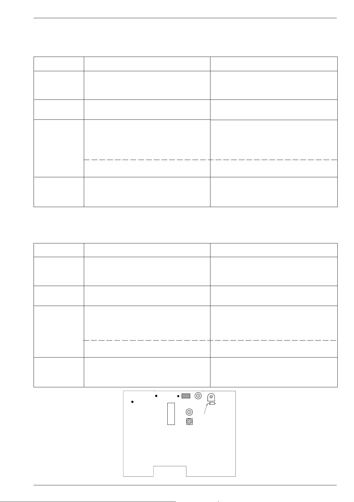
NF/AF
OUT
JP103
ANT. IN
JP101
JP102
IC101
GND
TC102
L103
L102
TC101
VR102
D103
VTUN
MAIN BOARD
GRUNDIG Service 2 - 1
 Loading...