

Page 1
72011 049 5200 (0498)
Es gelten die Vorschriften und Sicherheitshinweise gemäß dem Service Manual "Sicherheit", Sach-Nummer 72010-800.00, sowie zusätzlich die eventuell abweichenden, landesspezifischen Vorschriften!
The regulations and safety instructions shall be valid as provided by the "Safety" Service Manual, part number 72010-800.00, as well as the respective national deviations!
sonoclock 755
Änderungen vorbehalten
Subject to alteration
Page 2
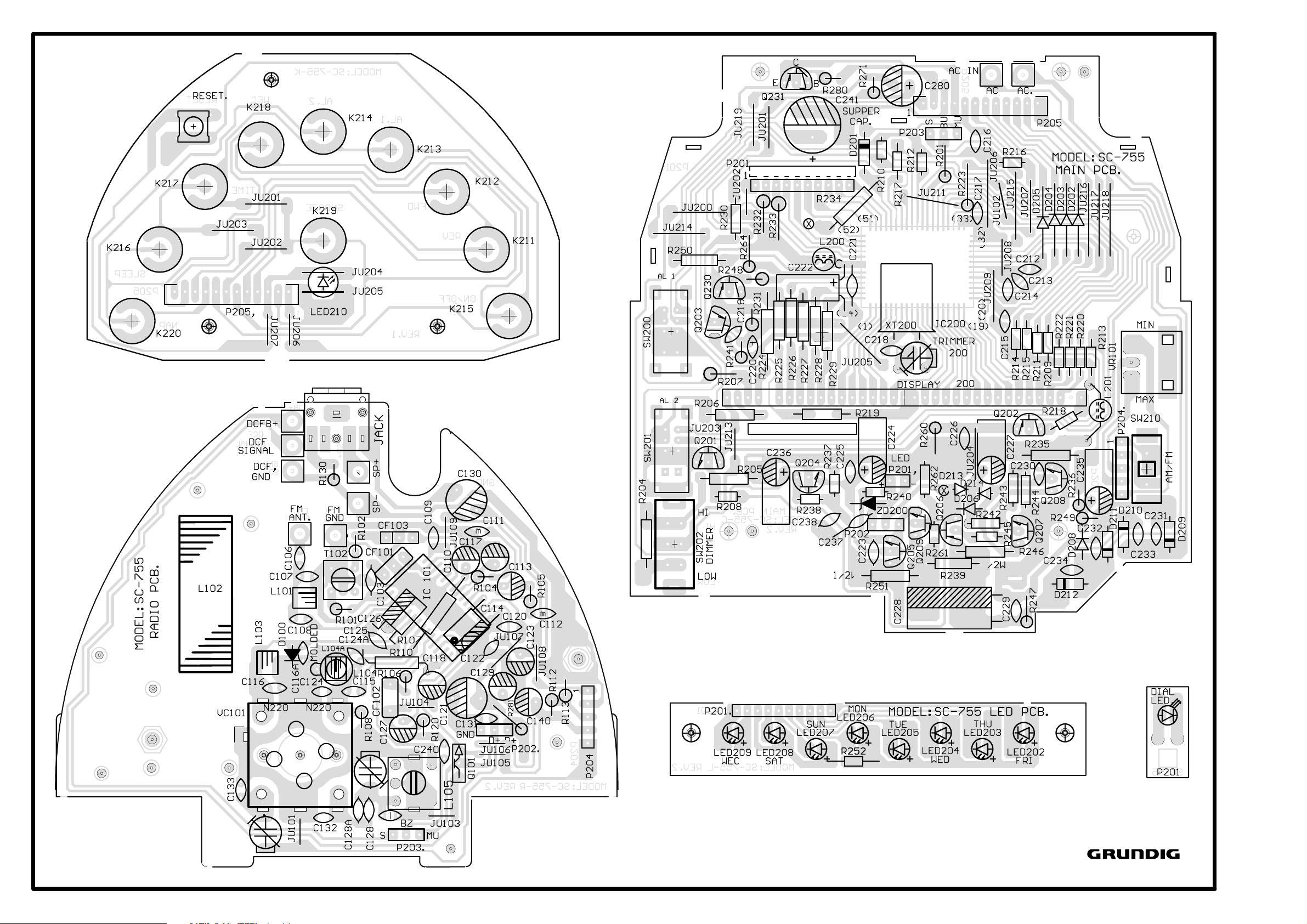
Druckplattenabbildungen / Illustration of Printed Boards
Bestückungsseite / Component side
sonoclock 755
72011 049 5200 (0498)
Änderungen vorbehalten
Subject to alteration
Page 3

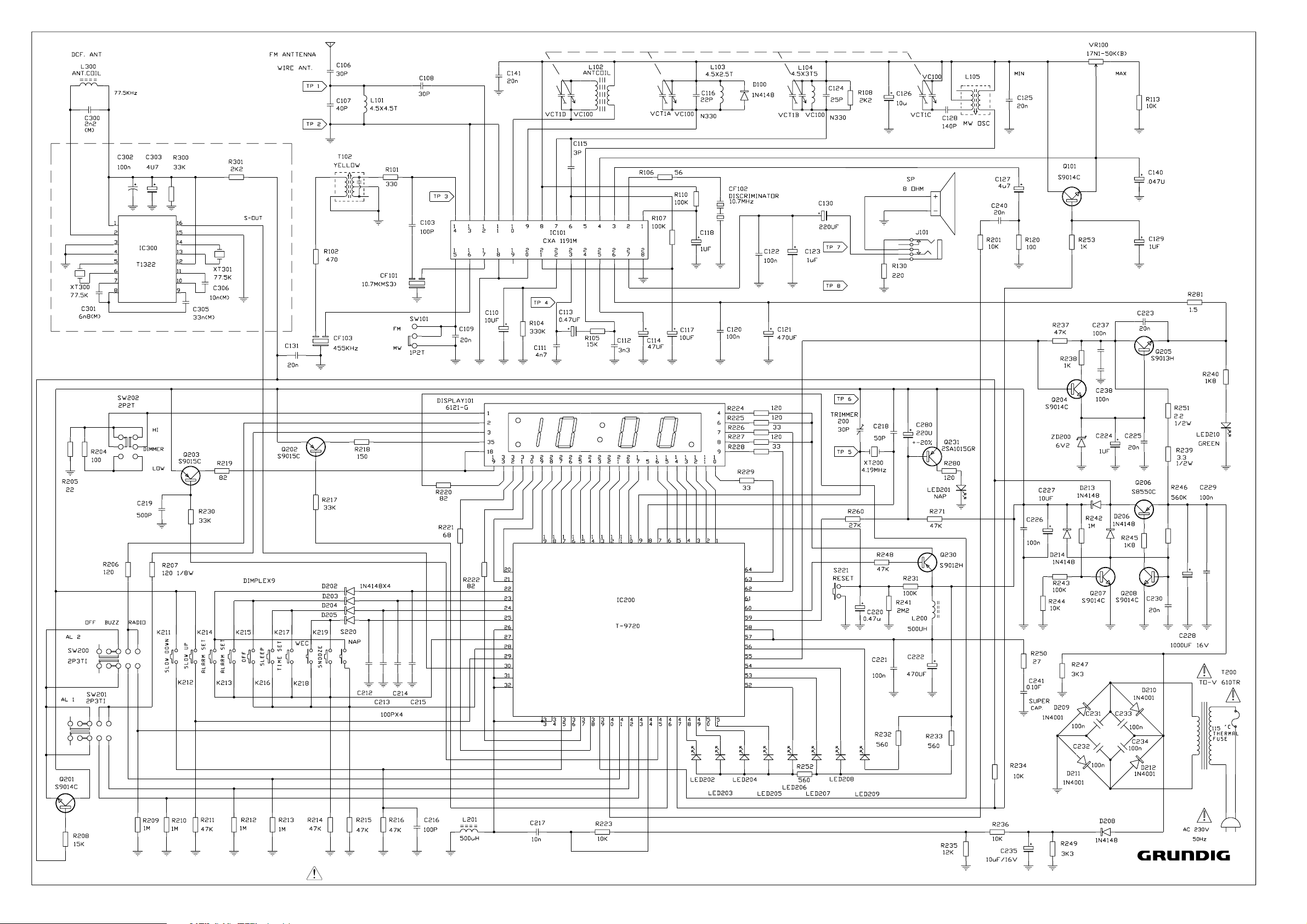
Verdrahtungsplan
Wiring Diagram
sonoclock 755
72011 049 5200 (0498)
Änderungen vorbehalten
Subject to alteration
Page 4

A L I G N M E N T P R O C E D U R E
MODEL NO. : SC-755
INSTRUMENTS REQUIRED GENERAL PREPARATION
1. Signal Generator 1. Check source voltage, DC or AC according to specifications
2. FM Signal Generator 2. Set function switch to band being aligned
3. Sweep Generator (10.7 MHz for FM) 3. Signal input should be kept as low as possible to avoid AGC and AFC function
4. VTVM 4. Standard modulation : AM 1 KHz 30% mod
FM IF ALIGNMENT
This model requires no FM IF alignment as the IF is fixed by ceramic filter and discriminator CF1 & CF2.
Please take note that correct type and same color dot of ceramic filter is used in servicing, diff color dot of ceramic filter
may cause worse IF 'S' curve characteristic and distortion.
Connect IF genescope output terminal to TP3 & TP2 (GND), connect scope input terminal to TP4 & TP2 (GND),
then the IF characteristic curve can be observed.
5. Oscilloscope FM 1 KHz 22.5 KHz dev
6. Frequency counter
7. Regulated DC power supply
AM IF ALIGNMENT
STEP
SIGNAL SOURCE (AM RF Gen.)
CONNECT TO
A standard radiation TP ( 4 ) Detector output terminal Quiet Volume control at
1 loop 465 KHz and ground Point T102 Maximum min. position
2 Repeat step 1 for max. output
SET SIGNAL TOALIGNMENT INDICATOR (Oscilloscope, VTVM)
CONNECT TO
SET RADIO
DIAL TO
ADJUST ADJUST FOR REMARKS
FM RF ALIGNMENT
STEP
1
2
3
4
5
SIGNAL SOURCE (FM Signal Gen.)
CONNECT TO
SET SIGNAL TOALIGNMENT INDICATOR (Oscilloscope, VTVM)
CONNECT TO
87.35 MHz (Lowest end) stretch or
(modulated) squeeze
TP ( 1 ) & ( 2 ) 108.25 MHz Terminals VCT1 B Volume
through matching network (modulated) across speaker (Highest end) (Osc. trimmer) Maximum control at
if necessary voice coil L103 (RF coil) max. position
88 MHz 88 MHz stretch or
(modulated) squeeze
106 MHz VCT1 A
(modulated) 106 MHz (RF trimmer)
Repeat steps 3 and 4 as necessary to minimize tracking error and also steps 1 and 2 if necessary
SET RADIO
DIAL TO
ADJUST
L104 (Osc. coil)
ADJUST
FOR
REMARKS
AM RF ALIGNMENT
STEP
1
2
3
4
5
SIGNAL SOURCE (AM Signal Gen.)
CONNECT TO
A standard radiation (modulated) Across speaker (Highest end) (Osc. trimmer) Maximum control at
loop ant. 588 KHz voice coil L102 max. position
Repeat steps 3 and 4 as necessary to minimize tracking error and also steps 1 and 2 if necessary
CLOCK FREQUENCY ALIGNMENT
SIGNAL SOURCE
CONNECT TO
No signal TP ( 5 ) and TP ( 6 ) with 10 : 1 test probe Through Any
72011 049 5200 (0498)
SET SIGNAL
TO
SET SIGNAL TOALIGNMENT INDICATOR (Oscilloscope, VTVM)
CONNECT TO
SET RADIO
DIAL TO
515 KHz L105
(modulated) (Lowest end) (Osc. coil)
1630 KHz VCT1 C Volume
(modulated) 558 KHz (ant. coil)
1440 KHz VCT1 D
(modulated) 1440 KHz (ant. trimmer)
ALIGNMENT INDICATOR (Frequency Counter)
CONNECT TO
SET RADIO
DIAL TO
ADJUST ADJUST FOR REMARKS
a cap. 1 pF to 3 pF. ( It depends on the sensitivity of Point Trimmer 200 Mhz
the frequency counter )
ADJUST
4.194304
ADJUST
FOR
REMARKS
Änderungen vorbehalten
Subject to alteration
 Loading...