

Page 1
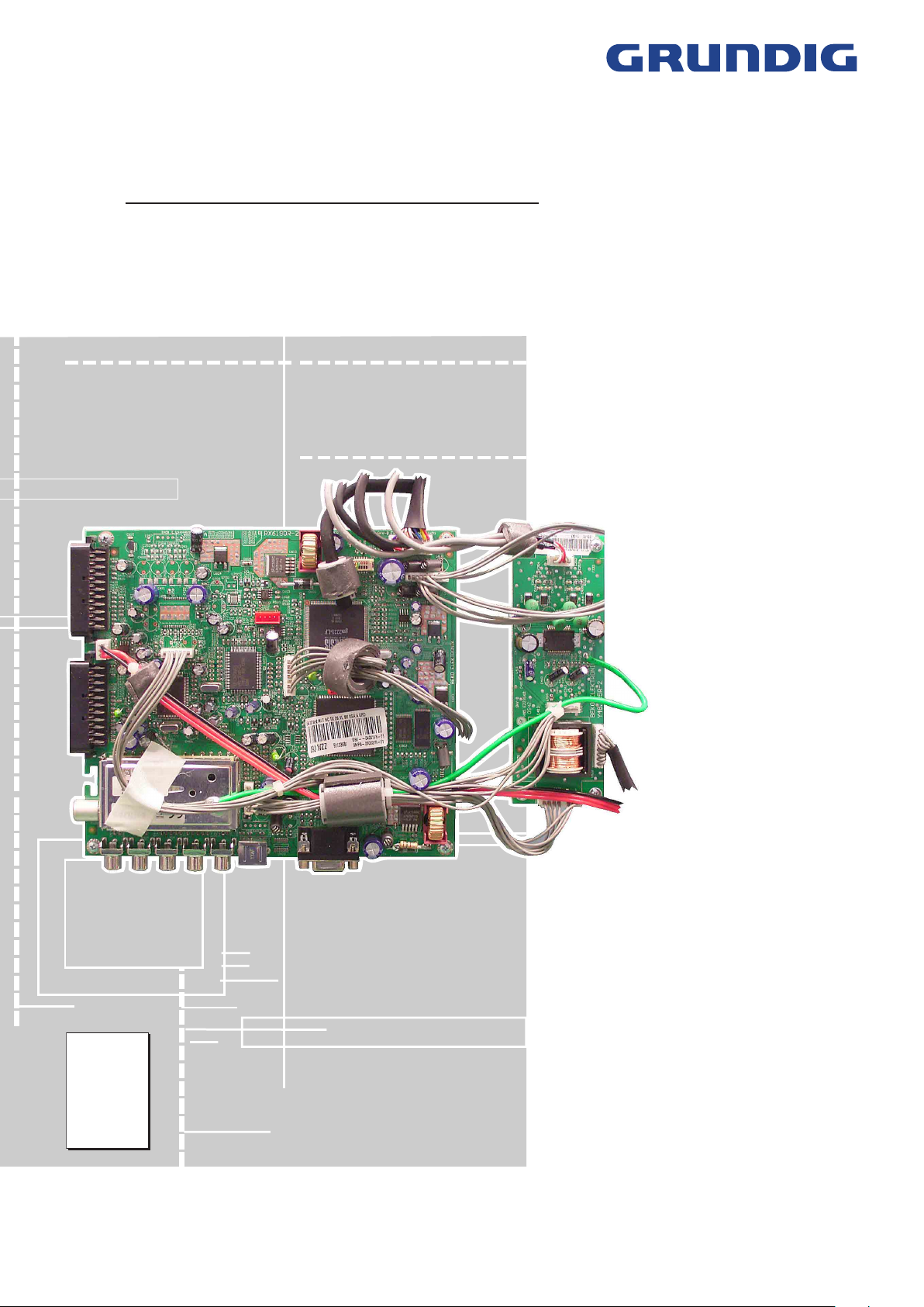
TV Service Manual
Service
Manual
Chassis
L5A-26"…32"
SEDANCE 27
LW 70-6605 Top GBE4100
SEDANCE 32
LW 82-6605 Top GBE4200
Zusätzlich erforderliche Unterlagen für den Komplettservice
Additionally required Service Documents for the Complete Service
Sicherheit
Safety
Materialnr./Part No.
720108000001
Materialnummer/Part Number 720100502000
Änderungen vorbehalten/Subject to alteration
TCC 0206 MP • Prepared in Germany
http://www.grundig.com
Page 2
GRUNDIG Service Chassis L5A-26"…32"
Es gelten die Vorschriften und Sicherheitshinweise
gemäß dem Service Manual "Sicherheit", Materialnummer 720108000001, sowie zusätzlich die eventuell abweichenden, landesspezifischen Vorschriften!
Inhaltsverzeichnis
Seite
Allgemeiner Teil .................................... 1-2…1-9
Allgemeine Hinweise .....................................................................1-2
Technische Daten ..........................................................................1-3
Bedienhinweise .............................................................................1-5
Service- und Sonderfunktionen .....................................................1-8
Platinenabbildungen
und Schaltpläne .................................. 2-1…2-15
Übersicht .......................................................................................2-1
Blockschaltplan ..............................................................................2-2
Hauptplatte RX6190 ......................................................................2-3
– Netzteil .......................................................................................2-7
– Tuner ..........................................................................................2-7
– IN/OUT.......................................................................................2-8
– VGA ...........................................................................................2-9
– Verstärker ..................................................................................2-9
– Video-Konverter .......................................................................2-10
– Telete�tTelete�t .....................................................................................2-11
– Scaler.......................................................................................2-12
Audio-Platte Y48195 ....................................................................2-14
Keyboards ZN4191 / ZS2191 ......................................................2-15
IR-Empfänger FX2193 .................................................................2-15
Netzschalterplatte FX2192 ..........................................................2-15
The regulations and safety instructions shall be valid
as provided by the "Safety" Service Manual, part
number 720108000001, as well as the respective
national deviations.
Table of Contents
Page
General Section .................................... 1-2…1-9
General Notes ...............................................................................1-2
Technical Data ...............................................................................1-3
Operating Hints ..............................................................................1-6
Service and Special Functions ......................................................1-8
Layout of PCBs
and Circuit Diagrams .........................2-1…2-15
Overview ........................................................................................2-1
Block Circuit Diagram ....................................................................2-2
Main Board RX6190 ......................................................................2-3
– Power Supply .............................................................................2-7
– Tuner ..........................................................................................2-7
– IN/OUT.......................................................................................2-8
– VGA ...........................................................................................2-9
– Amplifier .....................................................................................2-9
– Video Converter .......................................................................2-10
– Telete�t .....................................................................................2-11
– Scaler.......................................................................................2-12
Audio Board Y48195 ....................................................................2-14
Keyboards ZN4191 / ZS2191 ......................................................2-15
IR Receiver FX2193 ....................................................................2-15
Power Switch Board FX2192 .......................................................2-15
Ersatzteillisten ...................................... 3-1…3-3
Allgemeiner Teil
Allgemeine Hinweise
Achtung: ESD-Vorschriften beachten
Vor dem Öffnen des Gehäuses zuerst den Netzstecker ziehen!
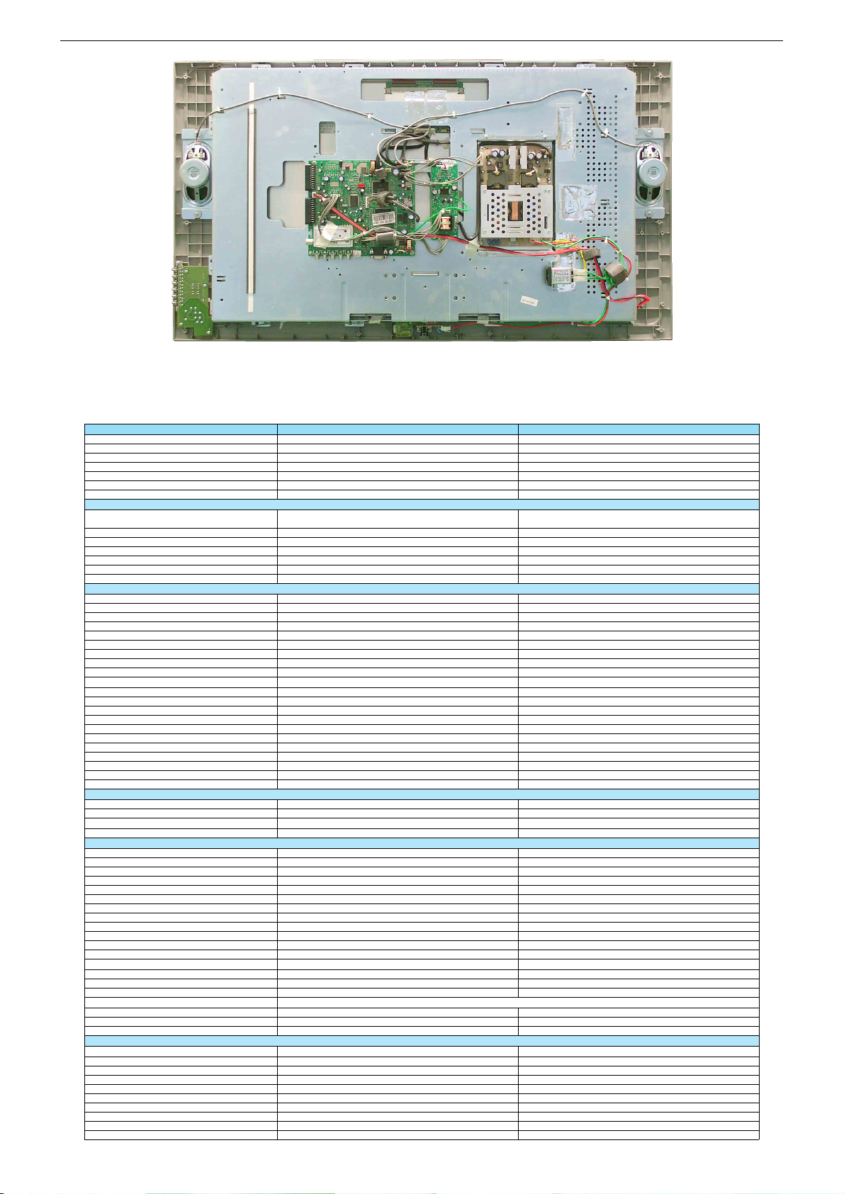
Leitungsverlegung
Bevor Sie die Leitungen und insbesondere die Masseleitungen lösen,
muss die Leitungsverlegung zu den einzelnen Baugruppen beachtet
werden.
Nach erfolgter Reparatur ist es notwendig, die Leitungsführung wieder
in den werkseitigen Zustand zu versetzen um evtl. spätere Ausfälle
oder Störungen zu vermeiden.
Durchführen von Messungen
Bei Messungen mit dem Oszilloskop an Halbleitern sollten Sie nur
Tastköpfe mit 10:1 - Teiler verwenden. Außerdem ist zu beachten, dass
nach vorheriger Messung mit AC-Kopplung der Koppelkondensator
des Oszilloskops aufgeladen sein kann. Durch die Entladung über das
Messobjekt können Bauteile beschädigt werden.
Messwerte und Oszillogramme
Bei den in den Schaltplänen und Oszillogrammen angegebenen
Messwerten handelt es sich um Näherungswerte!
Austausch der Chassisplatte
Nach Austausch der Chassisplatte müssen alle Einstellungen im Service
Mode nach Tabelle "Grundeinstellwerte" (Punkte 1 und 2 im Kapitel
"Service- und Sonderfunktionen" auf Seite 1-8) eingestellt werden.
Spare Parts Lists .................................. 3-1…3-3
General Section
General Notes
Attention: Observe the ESD safety regulations
Before opening the cabinet disconnect the mains plug!
Wiring
Before disconnecting any leads and especially the earth connecting
leads observe the way they are routed to the individual assemblies.
On completion of the repairs the leads must be laid out as originally
fitted at the factory to avoid later failures or disturbances.
Carrying out Measurements
When making measurements on semi-conductors with an oscilloscope,
ensure that the test probe is set to 10:1 dividing factor. If the previous
measurement was made on AC input, please note that the coupling
capacitor in the oscilloscope will be charged. Discharge via the item
being checked can damage the components.
Measured Values and Oscillograms
The measured values given in the circuit diagrams and oscillograms
are appro�imates!
Change of the Chassis Board
After changing the chassis board all settings in the service mode
must be done according to the table "Basic Settings" (points 1 and 2
in chapter "Service and Special Functions" on page 1-8).
1 - 2
Page 3
Technische Daten / Technical Data
Chassis L5A-26"…32"GRUNDIG Service
Order No.
Develop. order No.
EAN
Approbations
IM-Languages
Remote control
Color
DISPLAY
Panel
16:9 wide-screen format
Response time
Brightness
Contrast ratio
Viewing angle approx.
Physical display resolution max. pixel
PICTURE
Digital Reference-Plus-Technology (Motion Adaption)
Line Flicker Reduction
Motion Adaptive Deinterlacing
Digital Color Transition Improv. (DCTI)
Digital Combfilter
Digital Luminance Transition Improv. (DLTI)
Picture Noise Reduction (DNR)
CCS (Clear Color Screen)
Preset picture modes
Aspect ratios (Format switching)
PIP
Multifold Tuner scan (Mosaic Picture)
PAT: Split screen (PICTURE + TEXT)
PAP: Double Window (PICTURE + PICTURE)
P2AT: Double window + TXT
POP: PICTURE on PICTURE
Picture freezing
Zoom with point function
Auto 16:9 selection via Scart
Sharpness control
Blue Background
CHASSIS
TV-Chassis
Progressive
Tuner
Keyboard
ELECTRONIC
Stand by indicator
EPG (Electronic Programme Guide)
Easy Dialog
Megalogic
Manual & autom. labeling of prog.
Programmable off timer
Programmable on timer
Intelligent channel search (Zapping funct.)
Programme Edit
Intelligent Programme Switch
Auto switch off
Programme memory TV/AV (opt.)
Teletext/Fasttext/Toptext
Teletext options
Childlock
Youth free recognition
Menue languages OSD
SWAP (Recall function)
Service mode
Hotel mode
TUNING
Autom. Tuning System with country selection
Frequency Based Auto Search
Automatic Micro-search
Automatic Programming
Manual fine tuning
Direct channel selection
Direct frequency selection
PAL/SECAM/BG/DK/I/L’/L
NTSC-Playback via Scart (3,58/4,43)
Cable TV / Hyperband (S1-S41)
Sedance 27 LW 70-6605 TOP Sedance 32 LW 82-6605 TOP
G.BE 41-00
J9H
40 13833-60330 6
CE,CB
D,CH,E,P,NL,PL,H,CZ
TP 160 C
silver silver
27" / 70cm
Active Matrix TFT-LCD
[
ca. 8ms
ca. 550cd/m2
ca. 1000:1
176° vertical / 176° horizontal
WXGA 1366 x 768 WXGA 1366 x 768
\
\
\
\
[
\
[
\
user, natural, rich, soft
16:9 / 4:3
\
\
\
\
\
\
\
\
[
[
\ \
L5
PLL frequency synthesizer tuning
5 keys: menu, ± for programme, ± for volume
[
red LED red LED
\
\
\
[
[
[
[
[
\
\
99 / 5
[ / [ / [
250 pages
[
\
20 languages, D, GB, F, I, E, P, NL, HR, RUS, GR, DK, S, FIN, N, TR, PL, CZ, SK, SLO, H
[
[
\ \
full automatic sorting
\
[
\
[
[
\
[
[
[
5 keys: menu, ± for programme, ± for volume
G.BE 42-00
J9J
40 13833-60329 0
CE,CB
D,CH,E,P,NL,PL,H,CZ
TP 160 C
32" / 81cm
Active Matrix TFT-LCD
[
ca. 15ms
ca. 500cd/m2
ca. 800:1
170° vertical / 170° horizontal
\
\
\
\
[
\
[
\
user, natural, rich, soft
16:9 / 4:3
\
\
\
\
\
\
\
\
[
[
L5
PLL frequency synthesizer tuning
[
\
\
\
[
[
[
[
[
\
\
99 / 5
[ / [ / [
250 pages
[
\
[
[
full automatic sorting
\
[
\
[
[
\
[
[
[
1 - 3
Page 4
Chassis L5A-26"…32"GRUNDIG Service
AUDIO
Mono/Stereo/Nicam
AV Stereo
Loudspeaker
Virtual Dolby
Matched Sound Delay (Lip synchronous)
Subwoofer
Dynamic Bass
DSP (Digital Sound Processor)
Balance Adjustment
AVL (Audio Volume Level)
PIP listening via Headphone.jack
Equalizer
Space Sound Effect
Audio mode
Audio amplifier without extern LS
POWER SUPPLY / CABINET
Power voltage
Power switch
Integrated supply
Power consumption
Cabinet (WxHxD, cm)
Weight
REAR PANEL CONNECTIONS
Euro-AV-Socket AV1
Euro-AV Socket AV2
Euro-AV Socket AV3
S-Video
Camera-AV
Wireless
YUV input / progressive
PC-input (Sub D 15)
PC-Audio in
DVI
HDCP
HDMI
Headphones
Audio out
Antenna for terrestrial reception
DC-connector
Power supply plug
SUPPLIED ACCESSORIES
Remote control (incl. battery)
Power cord
Instruction manual
Circuit diagram
Wall fixture integrated
Sedance 27 LW 70-6605 TOP Sedance 32 LW 82-6605 TOP
[ / [ / [[ / [ / [
[
2 wide band lateral
\
\
\
\
\
[
[
\
5 Band
cinema, music, sport, speech, user
\
2 x 7/5W (music/nominal)
100 - 240V, 50/60Hz 100 - 240V, 50/60Hz
[
\
ca. 120W, standby < 2W
79 x 48 x 9.5cm
(18 cm with stand)
ca. 14.6kg ca. 17kg
CVBS in-/output, RGB input
CVBS in-/output
\
Hosiden
3x Cinch socket in
\
\
Multisync WXGA
\
\
\
\
3.5mm jack
1 x Coaxial-socket for TV-tuner-in, according to DIN 45325
2 x Cinch
[
[ [
[
[
[
\
\ \
[
2 wide band lateral
\
\
\
\
\
[
[
\
5 Band
cinema, music, sport, speech, user
\
2 x 7/5W (music/nominal)
[
\
ca. 129W, standby < 2W
91,5 x 57 x 10.5cm
(18 cm with stand)
CVBS in-/output, RGB input
CVBS in-/output
\
Hosiden
3x Cinch socket in
\
\
Multisync WXGA
\
\
\
\
3.5mm jack
1 x Coaxial-socket for TV-tuner-in, according to DIN 45325
2 x Cinch
[
[
[
[
\
1 - 4
Page 5
Bedienhinweise Dieses Kapitel enthält Auszüge aus der Bedienungsanleitung.
Weitergehende Informationen entnehmen Sie bitte der gerätespezifischen Bedienungsanleitung, deren Materialnummer Sie in der entsprechenden Ersatzteilliste finden.
1 - 5
Chassis L5A-26"…32"GRUNDIG Service
Page 6
1 - 6
Operating Hints This chapter contains excerpts from the operating instructions.
For further particulars please refer to the appropriate user instructions the
part number of which is indicated in the relevant spare parts list.
Chassis L5A-26"…32"GRUNDIG Service
Page 7
1 - 7
Chassis L5A-26"…32"GRUNDIG Service
Page 8
Chassis L5A-26"…32"GRUNDIG Service
g
g
g
g
g
(
)
AMIRA 17GRUNDIG Service
Service- und Sonderfunktionen
Tastenfunktionen
MENU
OK
P+/P–
ǸǸ
ǸǸ
TXT
Service-Mode aktivieren
– Taste "
– Zahlenfolge "8500" eingeben. Auf dem Bildschirm wird das
– Service Menüs "ADJUSTMENTS" und "SELECTIONS" mit der
Service-Mode beenden
– Taste "
1. Grundeinstellwerte
Die Grundeinstellwerte im Service Mode sind in der Tabelle enthalten.
Aufrufen des Dialog Centers
Aufrufen der Service Menüs
Menü-Zeile (Menüpunkt) wählen
/ Ƿ Wert ändern
Beenden des Service Mode
i
" (INFO-Menü) drücken.
Service Menü "OPTIONS" und der Softwarestand angezeigt.
OK
Taste "
" nacheinander aufrufen.
TXT
" drücken.
Service
Menü
Menu
OK
Menüpunkt
Point of Menu
P+ / P–
BG
DK
I
L
SCART 2
FAV
SVHS
HOTEL MODE
STBY RECALL
OPTIONS
RECALL LAST AV
MSP CARRIER MUTE
WSS RF
AUTO AV 16:9
FIRST ATS
BACKLIGHT POL
FACTORY MODE
WHITE R
WHITE G
WHITE B
BRI
CON
COL
PRESCALE FM
PRESCALE NICAM
ADJUSTMENTS
PRESCALE SCART
HOTEL VOLUME
AGC
FACTORY RESET
TUNER TYPE
TELETEXT
TIMER MODE
SELECTIONS
MSP CLIP
SWAP/ZAPP
Einstellung
Adjustment
Ǹ
/
Ƿ
PHILIPS
SAMSUNG
FAST&TOP
FAST
NO TEXT
OFF TIMER
SLEEP TIMER
REDUCE VOL
REDUCE TONE
COMPROMISE
DYNAMIC
ZAPP
SWAP
TV-Norm BG
TV-Norm DK
TV-Norm I
TV-Norm L/L'
Scart 2 Buchse / Socket
Front-AV-Buchsen / Sockets
S-VHS-Buchse / Socket
Das Menü "SUCHEN / ABSTIMMUNG" ist nicht mehr aufrufbar. Die maximale Lautstärke ist be-
grenzt (siehe Service-Menü "ADJUSTMENTS" – "HOTEL VOLUME").
The "SETUP" Menu is not accessible. The maximum adjustable volume value is limited (see service
menu "ADJUSTMENTS" – "HOTEL VOLUME").
OFF: Netz-Ein –> Standby / Power on –> standby
ON: Netz-Ein –> Pro
OFF: Netz-Ein –> Programm 1 / Power on –> Programme 1
ON: Netz-Ein –> zuletzt
Bei schlechtem Eingangs-Signal mutet der Sound-Prozessor MSP.
The Sound Processor MSP will mute the sound automatically if the si
Automatische Bild-Formatumschaltung auf 16:9 bei Empfang des "WSS"-Signales.
Automatic picture format switchin
Schaltspannung an Pin 8 der AV-Buchse schaltet automatisch auf das Bild-Format 16:9.
Volta
e at pin 8 of AV socket, picture format is switching to 16:9.
Beim nächsten Einschalten startet das Gerät mit ATS-Suchlauf.
Polarisation der Hintergrundbeleuchtung / Polarization of backlight
Service-Mode ist mit der Taste "SCAN" direkt aufrufbar.
Weißabgleich – Rot / White adjustement – red
Weißabgleich – Grün / White adjustement – green
Weißabgleich – Blau / White adjustement – blue
Grundeinstellwert für Helligkeit / Basic setting value for Brightness
Grundeinstellwert für Kontrast / Basic setting value for Contrast
Grundeinstellwert für Farbe / Basic setting value for Color
Grundlautstärke für FM-Ton / Basic setting value for FM sound
Grundlautstärke für NICAM-Ton / Basic setting value for NICAM sound
Grundlautstärke für SCART-Ton / Basic setting value for SCART sound
Maximale Lautstärke im Hotel-Mode / Hotel mode – volume maximum
AGC-Abgleich / AGC adjustment
Grundwerte werden geladen / Loading basic values
Eingebauten Tuner wählen
Select used tuner
FAST & TOP-Text
FAST-Text
Fester Ausschaltzeitpunkt / Fixed switch off timer XXX
Ausschaltzeitpunkt in 15…120 Minuten / sleep timer
MSP Sound-Optionen / Sound options MSP
Service and Special Functions
Functions of the buttons
MENU
OK
P+/P–
ǸǸ
ǸǸ
TXT
Calling up the Service Mode
– Press button "
– Enter the code number "8500". The Service Menu "OPTIONS"
– Step by step call up the Service Menu "ADJUSTMENTS" and
Exit the Service Mode
– Press button "
1. Basic Settings
The table shows all basic specific settings in the service mode.
ramm 1 / Programme 1
esehenes AV-Programm / Power on –> last used AV programme
to 16:9 during "WSS" signal reception.
Call up the Dialog Center
Call up the Service Menus
Call up the dialogue line (point of menu)
/ Ƿ Changing the settings
Exit the Service Mode
i
" (INFO Menu).
and the software version number are shown on the screen.
"SELECTIONS" with the button "
TXT
".
Hinweis
Hint
15…120 minutes
OK
nal quality is bad.
" .
Sedance 27
Sedance 32
LW 70-6605 TOP
LW 82-6605 TOP
ONONON
ON
ON
ON
ON
ON
ON
ON
ON
ON
ON
ON
OFF
OFF
OFF
OFF
OFF
OFF
ON
ON
ON
ON
ON
ON
OFF
OFF
ON
ON
OFF
OFF
128
128
128
128
128
128
130
130
158
158
128
128
19
19
40
40
16
16
30
30
19
19
X
XX
XX
1 - 8
1 - 8
Page 9

Chassis L5A-26"…32"GRUNDIG Service
AMIRA 17GRUNDIG Service
2. Austausch der Hauptplatte oder des U502
Nach dem Austausch der Hauptplatte oder des U502 sind Grundeinstellwerte im Service Mode entsprechend der Tabelle einzustellen.
3. Software-Versionsnummer
Die Software-Versionsnummer wird oben im Service-Menü angezeigt, z.B.:
L5AGNA_V1.16 - 04.08.2005
SL532WG_SH01_T 15
4. Programmsuchlauf
i
– Taste "
– "SUCHEN / ABSTIMMUNG" mit den Tasten P+ /
– "PROGRAMMSUCHLAUF" mit den Tasten P+ /
– Land mit den Tasten
" (INFO-Menü) drücken.
und mit der Taste "
mit der Taste "
MENU
MENU
" bestätigen.
" bestätigen.
P+ / P–
P–
anwählen
P–
anwählen und
, Ǹ / Ƿ auswählen und mit der Taste
"OK" bestätigen.
Das automatische Sendersuchsystem stoppt bei jedem empfangswürdigen Sender (AFC und Koinzidenz) und speichert automatisch die entsprechenden Senderdaten mit dem jeweiligen
Standard. Danach wird der Suchlauf fortgesetzt.
Zum Abbrechen des Suchlaufes die blaue Taste drücken.
2. Change the Main Board or the U502
After changing the Main Board or U502 all basic settings in the service mode must be done according to the table.
3. Software Version Number
The software version number is shown on the upper part of the service menu, e.g.:
L5AGNA_V1.16 - 04.08.2005
SL532WG_SH01_T 15
4. Programme Search
– Press button "
– Select "SETUP" with the buttons
"
MENU
– Select "STATION SEARCH" with the buttons P+ /
with button "
– Select the Country with the buttons
i
" (INFO Menu).
P+ / P–
and confirm with button
".
P–
MENU
".
P+ / P–
, Ǹ / Ƿ and confirm
and confirm
with button "OK".
The autoprogram system stops at every station of acceptable reception quality (AFC and coincidence) and stores the station data
and the respective standard automatically. The system then continues searching.
Pressing the blue button stops the programme search.
1 - 9
1 - 9
Page 10

Platinenabbildungen und Schaltpläne / Layout of PCBs and Circuit Diagrams
+5V
+3.3V_STBY
POWER
ST_BY
PNL_EN
+5V_STBY
+2.5V
+3.3V
PANEL_POWER
+1.8V_STBY
+12V
+8V
STAND_BY_2
POWER SUPPLY
+5V
SCL5V
SDA5V
SIF
AM_MONO
CVBS_IF
SC1_OUT_V
TUNER
CVBS_IF
YCOE
SC_R
SC_G
SC_B
SC2_IN_V
SC1_IN_V
SC2_OUT_V
CVBS_TXT
O_HS
R_TXT
G_TXT
B_TXT
FB_TXT
O_VS
+5V
+3.3V
SDA5V
SCL5V
RESET
YUV[0..7]
SVHS_Y
SVHS_C
VCLK
VIDEO CONVERTER
SCL3V
SDA3V
SDA5V
SCL5V
DDC_SDA_VGA
DDC_SCL_VGA
RED+
RED-
GREEN+
GREEN-
BLUE+
BLUE-
+3.3V_STBY
+1.8V_STBY
RESET
+5V_STBY
PNL_EN
PANEL_POWER
ST_BY
VCLK
YCOE
YUV[0..7]
5221_IO2
5221_IO1
MUTE
FB_SC
VS_PC
HS_PC
SOG_MCSS
VGACON
SC2_PIN8
SC1_PIN8
STAND_BY_2
TXD
RXD
PC_SD_SW
SCALER
+3.3V
+2.5V
SDA3V
SCL3V
CVBS_TXT
B_TXT
FB_TXT
O_VS
O_HS
RESET
R_TXT
G_TXT
5221_IO1
5221_IO2
+5V
TELETEXT
POWER
SCL5V
SDA5V
RESET
SVHS_C
SVHS_Y
+5V
SIF
FB_SC
MUTE
SC1_IN_V
RED+
RED-
GREEN+
GREEN-
BLUE+
BLUE-
SC2_IN_V
DDC_SDA_VGA
DDC_SCL_VGA
SC_B
SC_G
SC_R
+12V
AM_MONO
SC1_OUT_V
SC2_OUT_V
+8V
VS_PC
HS_PC
SOG_MCSS
VGACON
SC1_PIN8
SC2_PIN8
SWIN
TXD
RXD
PC_SD_SW
IN/OUT, VGA, AMPLIFIER
R_TXT
G_TXT
B_TXT
FB_TXT
O_VS
O_HS
CVBS_TXT
SVHS_Y
SVHS_C
SC1_IN_V
SC2_IN_V
RESET
SCL3V
SDA3V
+3.3V
+5V
+2.5V
POWER
SCL5V
SDA5V
SIF
SC_R
SC_G
SC_B
+12V
VCLK
YCOE
SCL5V
SDA5V
SDA3V
SCL3V
RESET
+3.3V_STBY
+1.8V_STBY
+5V_STBY
YUV[0..7]
PANEL_POWER
PNL_EN
ST_BY
RED+
RED-
GREEN+
GREEN-
BLUE+
BLUE-
DDC_SDA_VGA
DDC_SCL_VGA
AM_MONO
SC2_OUT_V
MUTE
FB_SC
SC1_OUT_V
+8V
5221_IO1
5221_IO2
VS_PC
HS_PC
SOG_MCSS
VGACON
SC1_PIN8
SC2_PIN8
SWIN
ST_BY
+5V
+12V
SUBWOOFER
Option
SWIN
+12V
+5V
PC_SD_SW
TXD
RXD
Übersicht / Overview
P.2-7 P.2-10 P.2-11
GRUNDIG Service Chassis L5A-26"…32"
2 - 1
P.2-7
P.2-12
P.2-8/2-9
Page 11

+3.3V_STBY
F600
+1.8V_STBY
T5A/250V
STAND_BY_2
PNL_EN
3.3V
+8V
+12V_AMP
PANEL_POWER
5V
+24V_INVERTER
+3.3V
+2.5V
+5V
+5V
+5V_STBY
+12V
+12
Power Supply Board
Audio Board
L402
LM2576
U600
78L08
U606
LM1117
1.8V
U605
U603
LM1117
3.3V
U602
SDI9933ADY
LM117-3.3V
U604
+5V_STBY
Tuner IF
U100
Video Decoder
VPC 3230D
Scart 1 FAV Scart 2
VGA-IN
CVBS-IF
SVHS-Y/C SC1-RGB
YU V
HS/VS
HS/VS
RGB
FB
CVBS
SDA/SCL 5V
SDA/SCL 5V
SDA/SCL 3V
SIF/AM-mono
L
R
L
R
L
R
PNL_EN ST_BY MUTE RESET
RESET
RESET
RESET
BR1_ADJ
BLK_EN
VGA_RGB
VGA HS/VS
S505
PROGRAMMING
CONNECTOR
U502
EEPROM
24C16
KEYBOARD
CON. S507
CON. S509
S511
LVDS
CONNECTOR
(30 PINS)
S502
U302
K6T1008V2
ESRAM
(Optional)
U300
M29W040
Flash
Q501/Q502
I2C 3V<->5V
U304
EEPROM
24LC16
U403
TDA1308
Headphone Amplifier
U402
TA2024
Stereo Amplifier
U401
MSP3410G
AUDIO DECODER
DISPLAY
BACKLIGHT UNIT
INVERTER
U500
GM 5221
LCD CONTROLLER
U503
SERIAL FLASH
M25P40
U400
EEPROM
24LC02
F601
T5A/250V
ST_BY
Audio Board
U402, TA2024
Stereo Amplifier
MUTE
MUTE
U301
Teletext Decoder
SDA 5550
S421
AC In
S421S603
TO263
U610
GRUNDIG Service Chassis L5A-26"…32"
Blockschaltplan / Block Circuit Diagram
2 - 2
Page 12

Hauptplatte
Main Board RX6190
Ansicht von der Bestückungsseite
View of Component Side
2 - 3
GRUNDIG Service Chassis L5A-26"…32"
Page 13

GRUNDIG Service Chassis L5A-26"…32"
Hauptplatte / Main Board RX6190
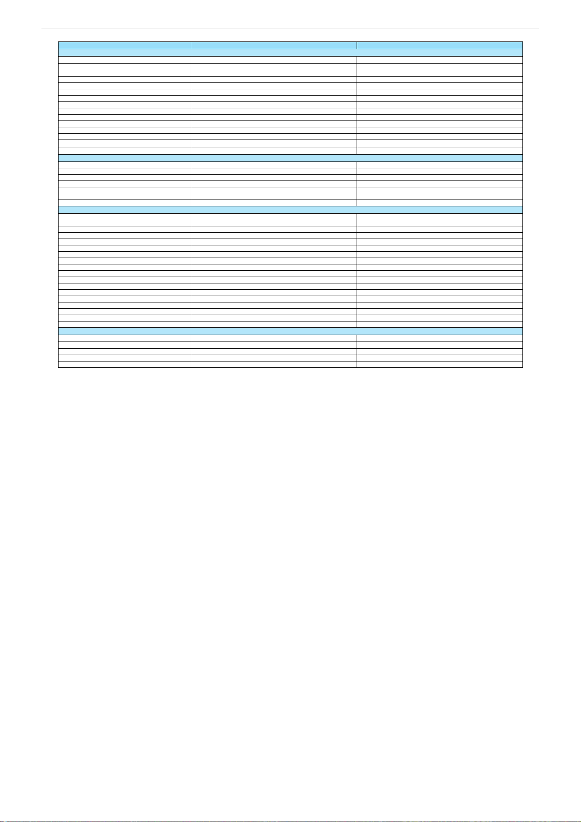
Koordinaten für die Bauteile / Coordinates of the Components
POS. X Y POS. X Y POS. X Y POS. X Y POS. X Y POS. X Y POS. X Y POS. X Y
C100 80 71
C101 69 99
C102 69 93
C103 98 90
C104 99 94
C105 99 96
C106 89 112
C107 84 112
C108 73 112
C109 69 102
C110 65 99
C111 93 87
C112 95 89
C113 95 91
C114 95 94
C115 95 96
C116 95 98
C117 95 100
C118 99 99
C119 78 82
C120 71 112
C121 100 90
C122 99 113
C123 87 79
C124 76 76
C125 60 97
C126 96 108
C127 102 79
C128 65 102
C129 81 82
C130 81 79
C131 83 82
C132 83 79
C133 61 93
C134 65 93
C135 57 106
C136 69 104
C137 94 80
C139 93 84
C140 71 82
C141 82 119
C142 91 112
C143 87 115
C144 79 117
C145 73 119
C147 109 78
C200 19 60
C201 83 43
C202 31 58
C203 93 55
C204 25 62
C205 83 54
C206 88 48
C207 96 62
C208 87 61
C209 93 57
C210 34 58
C211 93 53
C212 19 57
C213 41 57
C214 15 117
C250 50 158
C251 38 158
C252 47 161
C253 35 161
C254 49 164
C255 43 161
C256 39 161
C257 32 164
C258 43 137
C259 34 128
C260 105 19
C261 105 12
C262 96 12
C263 101 12
C264 103 12
C265 99 12
C266 32 84
C267 32 87
C268 23 81
C269 23 84
C270 29 82
C271 29 84
C300 139 45
C301 142 45
C302 144 45
C303 143 89
C304 145 89
C305 160 53
C306 171 53
C307 136 89
C308 116 48
C309 112 46
C310 106 51
C311 151 91
C312 158 97
C313 111 85
C314 128 90
C315 128 94
C316 110 101
C317 119 41
C318 122 41
C319 128 45
C320 130 45
C321 133 45
C322 126 94
C400 134 28
C401 132 30
C402 126 30
C403 128 30
C404 119 28
C405 121 30
C406 146 23
C407 33 73
C408 42 99
C409 29 87
C410 33 69
C411 34 121
C412 56 87
C413 16 105
C414 18 81
C415 15 75
C416 51 12
C417 19 134
C418 41 12
C419 24 130
C421 56 94
C422 53 137
C423 27 107
C424 15 77
C425 15 81
C426 15 67
C427 15 73
C428 53 12
C429 15 130
C430 19 132
C431 43 12
C432 19 126
C433 19 130
C434 45 12
C435 15 61
C436 35 12
C437 15 71
C438 44 99
C439 47 99
C440 62 83
C441 15 12
C442 49 99
C443 44 102
C444 60 83
C445 29 12
C446 51 99
C447 55 102
C448 60 73
C449 16 109
C450 16 102
C451 116 24
C452 112 24
C453 28 78
C454 20 69
C455 55 65
C456 27 125
C457 29 113
C458 65 80
C459 67 72
C460 42 111
C461 29 70
C462 34 64
C463 31 92
C464 38 100
C465 58 78
C466 83 41
C467 36 69
C468 38 69
C469 41 65
C470 46 65
C471 33 136
C472 58 136
C473 41 117
C474 20 113
C475 18 102
C476 60 68
C477 20 118
C478 23 98
C479 56 92
C480 53 99
C481 56 90
C482 26 103
C483 31 99
C484 54 112
C485 16 112
C486 32 106
C487 15 119
C488 15 123
C489 136 37
C490 135 45
C493 51 117
C494 57 117
C495 27 138
C496 50 155
C497 45 155
C498 38 155
C499 33 155
C500 129 135
C505 141 99
C506 138 99
C507 136 99
C508 157 102
C509 158 105
C511 127 99
C513 142 136
C514 110 109
C515 142 138
C516 110 131
C519 153 131
C520 109 122
C521 109 118
C522 110 107
C523 142 141
C524 142 143
C525 110 104
C527 153 117
C529 139 91
C530 146 101
C531 134 99
C532 132 99
C533 129 99
C534 147 113
C536 152 139
C537 164 102
C538 170 130
C539 169 108
C540 145 95
C541 157 139
C543 122 99
C545 167 113
C546 151 96
C547 125 99
C548 153 102
C549 149 102
C550 160 131
C600 159 16
C601 178 55
C602 99 135
C603 99 137
C604 147 6
C605 183 68
C606 183 75
C607 170 98
C608 184 114
C609 171 113
C610 23 165
C611 23 156
C612 61 141
C613 57 152
C615 23 150
C617 170 42
C619 67 123
C620 170 86
C621 181 106
C622 170 122
C623 61 146
C627 83 138
C628 57 158
C630 155 149
C631 168 152
C632 127 162
C633 135 162
C636 96 38
C700 66 135
C701 82 135
C702 70 135
C703 67 140
C705 84 135
C707 82 130
C708 77 127
C709 69 130
C711 79 127
C714 75 127
D400 150 23
D401 150 26
D402 131 22
D403 127 22
D404 123 22
D405 148 18
D406 142 18
D407 54 143
D408 46 143
D409 39 143
D410 31 143
D600 83 152
D601 165 5
D602 112 142
F600 105 28
F601 106 38
J100 74 82
J102 87 112
J200 43 57
J303 112 58
J304 164 53
J305 169 53
J306 167 53
J307 174 53
J309 150 43
J310 155 43
J312 110 81
J401 57 12
J402 15 99
J403 55 117
J404 58 131
J405 62 129
J410 131 18
J411 127 18
J412 123 18
J413 116 18
J414 111 18
J415 179 33
J416 179 35
J417 179 38
J418 179 40
J419 179 42
J500 105 74
J501 148 134
J504 90 70
J505 107 133
J506 97 71
J509 163 134
J512 139 142
J513 138 139
J514 137 142
J515 136 139
J516 135 142
J517 134 139
J518 133 142
J519 131 139
J520 130 142
J521 129 139
J536 102 108
J537 102 110
J550 139 158
J551 146 145
J552 146 158
J553 141 158
J554 142 145
J555 143 158
J556 146 143
J601 113 151
J602 111 151
J610 89 35
J611 89 37
J612 89 39
L100 95 113
L101 59 103
L102 79 122
L103 90 117
L200 20 76
L201 100 55
L300 107 46
L301 157 90
L302 160 90
L303 118 93
L400 40 62
L401 60 70
L402 37 105
L403 49 12
L404 39 12
L405 36 110
L406 59 111
L407 52 150
L408 45 150
L409 37 150
L410 30 150
L411 27 135
L412 25 82
L413 26 84
L414 100 17
L500 163 96
L501 175 133
L502 169 116
L503 151 98
L600 155 12
L601 182 59
L602 179 20
L603 179 17
L610 182 152
L611 174 152
L612 179 139
L613 171 139
L614 115 158
L615 115 160
L616 91 23
L621 91 30
L623 98 23
L700 77 145
L701 83 132
P400 8 139
P401 125 11
P402 8 80
Q100 103 83
Q200 87 51
Q201 83 51
Q202 92 49
Q300 112 96
Q404 136 40
Q405 68 63
Q406 68 67
Q410 59 126
Q500 107 127
Q501 87 70
Q502 93 71
Q503 151 135
Q504 166 140
Q505 166 135
Q506 105 68
Q507 83 21
Q610 83 142
Q611 92 142
Q700 83 127
R101 106 79
R102 111 78
R108 69 107
R109 69 109
R110 76 82
R111 104 79
R112 106 83
R113 69 97
R114 69 95
R115 65 97
R116 65 95
R117 99 83
R119 99 101
R120 99 86
R121 99 79
R200 83 48
R201 83 46
R202 15 115
R203 36 58
R204 38 57
R205 92 45
R206 88 46
R207 88 43
R208 88 54
R209 88 57
R300 113 92
R301 111 92
R302 112 71
R303 112 64
R304 128 48
R305 130 48
R306 133 48
R307 162 53
R308 110 99
R311 112 67
R313 112 44
R314 112 48
R315 117 88
R316 112 69
R317 112 51
R320 112 62
R321 112 60
R322 112 55
R323 112 53
R324 148 43
R325 153 43
R400 134 24
R401 132 26
R402 126 26
R403 128 26
R404 119 24
R405 121 26
R406 135 21
R407 123 26
R408 85 12
R409 15 153
R410 119 21
R411 91 12
R412 116 21
R413 111 21
R414 15 132
R415 15 144
R416 15 147
R417 15 95
R418 133 38
R419 138 21
R420 145 18
R421 55 70
R422 55 73
R423 142 22
R424 142 24
R425 53 117
R426 123 30
R427 15 134
R428 152 20
R429 115 28
R430 152 18
R431 114 21
R432 112 27
R433 15 83
R434 46 114
R435 49 114
R436 24 110
R437 46 117
R438 24 107
R439 15 137
R440 15 86
R441 15 79
R442 15 65
R443 47 12
R444 15 128
R445 37 12
R446 19 128
R447 55 12
R448 49 117
R449 15 63
R450 15 125
R451 15 121
R452 15 69
R453 18 12
R454 32 12
R455 88 41
R456 56 83
R457 48 102
R458 52 102
R460 55 99
R461 20 102
R462 24 113
R463 23 103
R464 56 85
R465 45 158
R466 33 158
R467 44 117
R469 15 149
R470 137 45
R471 72 64
R472 72 68
R473 64 66
R474 64 62
R480 63 126
R481 58 129
R500 112 136
R501 109 116
R502 105 118
R503 105 116
R504 101 123
R505 98 130
R506 153 129
R507 149 129
R508 149 126
R509 153 126
R510 149 124
R511 109 124
R512 153 124
R513 164 113
R514 161 113
R515 149 122
R516 153 122
R517 149 119
R518 153 119
R519 159 113
R520 149 117
R521 156 113
R522 154 113
R523 151 113
R524 149 113
R525 160 118
R526 149 110
R527 149 131
R528 162 142
R529 162 140
R530 123 95
R531 146 134
R532 163 137
R533 160 134
R534 84 71
R535 87 67
R536 93 67
R537 99 71
R538 107 131
R539 120 99
R540 148 139
R541 150 139
R542 108 68
R543 164 131
R544 164 118
R545 109 72
R546 139 41
R547 105 72
R548 114 79
R549 99 103
R550 96 17
R551 81 12
R552 166 152
R553 164 152
R580 148 158
R600 86 135
R602 89 131
R635 169 11
R640 80 142
R641 86 142
R642 88 142
R643 86 138
R700 86 130
R701 86 127
RG100 81 112
RG101 77 112
S300 155 66
S400 71 5
S401 11 108
S404 87 5
S405 57 5
S406 43 5
S407 15 5
S408 29 5
S409 41 165
S420 184 43
S421 48 107
S502 135 151
S505 94 125
S507 104 95
S509 104 96
S510 68 12
S511 164 158
S600 166 164
S601 87 16
S602 84 31
S603 174 145
S700 75 141
TU201 45 36
U100 81 97
U101 85 119
U300 172 67
U301 133 69
U302 163 67
U304 106 62
U400 142 29
U401 44 84
U402 46 127
U403 20 108
U410 101 6
U500 128 117
U502 99 117
U503 163 124
U600 166 19
U602 92 136
U603 182 83
U604 69 154
U605 178 116
U606 24 160
U610 102 151
U700 76 134
Y100 65 89
Y300 120 45
Y400 45 69
Y500 151 106
2 - 4
Page 14

GRUNDIG Service Chassis L5A-26"…32"
Hauptplatte / Main Board RX6190
Ansicht von der Bestückungsseite / View of Component Side
2 - 5
Page 15

GRUNDIG Service Chassis L5A-26"…32"
2 - 6
Page 16

VIN
1
ON/OFF5VOUT
2
GND
3
FBK
4
U600 LM2576
S1
1
G1
2
S2
3
G2
4
D1
8
D1
7
D2
6
D2
5
U602
SI9933ADY
C600
100N
C601
100N
D601
1N5820
L602
PE-54040
GND GND
GND
GND
+5V_STBY
+5V_STBY
ST_BY
C602
100N
GND
GND
+5V
IN
3
GND
2
OUT
1
U606
78L08
IN
3
1
OUT
2
ADJ
U604
LM1117-3.3V
+5V_STBY
C619
100U16V
C621
100U16V
C622
100U16V
C623
100U16V
C607
100N
C609
100N
C611
100N
C610
100N
C608
100N
C606
100N
C612
100N
C613
100N
+5V_STBY
GND
GND
GND
+3.3V_STBY
+1.8V_STBY
+8V
+5V +3.3V
GND
D600
+2.5V
GND
+12V
IN
3
1
OUT
2
ADJ
U603 LM1117 3.3V
IN
3
1
OUT
2
ADJ
U605 LM1117 1.8V
C603
100N
L603
100uH
C617
1000U16V
C627
100N
C628
100U16V
C620
470U
R602
1K
C615
100U
L601
3.3uH
C605
1000U16V
C604
1000U16V
L600
3.3uH
R635
150R
F600
+12V
C631
100N
GND
+12
VIN
1
ON/OFF5VOUT
2
GND
3
FBK
4
U610 TO263
C633
0603
D602
1N5820
L614
GND
123456789
10
S603
MHDR1X10
GND
+12
STAND_BY_2
GND
1
2
3
4
5
6
7
8
9
10
S600MHDR1X10
GND
+24V_INVERTER
J602
jumper tel
J601
jumper tel
L615
1uH
F601
GND
L610100uH
L611100uH
L612
100uH
L613
100uH
L621
100uH
L623
100uH
1
2
3
4
5
6
7
S602
MHDR1X7
1
2
3
4
5
S601
MOLCON5
STAND_BY_2
GND
+3.3V
+5V
+12V_AMP
PANEL_POWER
+24V_INVERTER
C632
1000U
+5V_STBY
R641
10K
R643
10K
GND
GND
Q611
BC848B
Q610
BC848B
R600
2K2
R640
22K
R642
22K
+5V_STBY
+12V_AMP
C630
1000U35V
STAND_BY_2
H1
Montaj DelikleriH2Montaj Delikleri
H4
Montaj Delikleri
GND
GND
GND
H5
Montaj Delikleri
GND
L616
100uH
J610
0R
J611
0R
J612
0R
PNL_EN
C636
1000U
T5A/250V
T5A/250V
1
30
SDA
5
AS
6
SIF
11
CVBS
12
5V
13
AF
14
SCL
4
NC
1
NC
2
+5V
3
NC
9
NC
10
GND15GND16GND17GND
18
TU201
TUNER_PHILIPS
GND
R204
100R
R203
100R
SCL5V
SDA5V
+5V
C200
100N
GND
GND
J200
0R
GND
SIF
AM_MONO
C201
220N
R205
220R
R207
220R
Q200
BC848B
Q201
BC848B
GND
R200
470R
R201
470R
GND
CVBS_IF
SC1_OUT_V
TP201
C205
100N
C206
100N
GND
GND
C204
470U16V
C207
100U16V
GND
SCL5V
SDA5V
+5V
C203
100N
C208
100U
+5V
Q202
BC858B
+5V
C211
220P
C209
1N
C210
220P
C202
1N
GND GND
L201
47uH
L200
47uH
C213
33P
C212
33P
GND
GND
R206
4K7
R208
4K7
R202
56R
R209
4K7
GND
C214
2N2
9
108
6
7
1 6 7 8 9
0
º
GRUNDIG Service Chassis L5A-26"…32"
Hauptplatte – Netzteil / Main Board – Power Supply
to Audio Board
p. 2-14, S422
to Inverter Board
Hauptplatte / Main Board – Tuner
to Power Supply Board
2 - 7
Page 17

13579
1113151719
24681012141618
20
21
P400
SCART 1
13579
1113151719
24681012141618
20
21
P402
SCART 1
1
2
S400
RCA VIDEO
NC1I2C_CL2I2C_DA3I2S_CL4I2S_WS5I2S_DA_OUT6I2S_DA_IN17ADR_DA8ADR_WS9ADR_CL10DVSUP11DVSUP12DVSUP13DVSS14DVSS15DVSS16I2S_DA_IN217NC18NC19NC20RESETQ21NC22NC23DACA_R
24
DACA_L
25
VREF2
26
DACM_R
27
DACM_L
28
NC
29
DACM_SUB
30
NC
31
NC
32
SC2_OUT_R
33
SC2_OUT_L
34
VREF1
35
SC1_OUT_R
36
SC1_OUT_L
37
CAPL_A
38
AHVSUP
39
CAPL_M
40
NC41NC
42
AHVSS43AHVSS
44
AGNDC
45
NC
46
SC4_IN_L
47
SC4_IN_R
48
ASG
49
SC3_IN_L
50
SC3_IN_R
51
ASG
52
SC2_IN_L
53
SC2_IN_R
54
ASG
55
SC1_IN_L
56
SC1_IN_R57VFERTOP
58NC59
MONO_IN
60
AVSS61AVSS
62
NC63NC
64
AVSUP
65
AVSUP
66
ANA_IN1+
67
ANA_IN-
68
ANA_IN2+
69
TESTEN
70
XTAL_IN
71
XTAL_OUT
72
TP
73
AUD_CL_OUT
74
NC
75
NC
76
D_CTR_I/O_1
77
D_CTR_I/O_0
78
ADR_SEL
79
STBYQ
80
U401
MSP-PQFP80
R421
100R
R422
100R
SCL5V
SDA5V
GND
C4481NC476
10P
C412
100N
RESET
R464
220R
GND
GND
1
2
3
S401
To Headphone
GND
GND
GND
C447
1N
C443
1N
R458
2K2
R457
2K2
GND
GND
GND
C408
100N
GND
C439
1N
C438
1N
GND
GND
R450
330R
R451
330R
C453
3.3U50V
C409
100N
GND
GNDGND
C415
220N
C419
220N
C414
220N
C417
220N
C416
220N
C418
220N
C433
1N
C425
1N
C430
1N
C431
1N
C428
1N
C427
1N
R441
1K
R442
1K
R446
1K
R444
1K
GND
GND
GND
GND
GND
GND
1
2
S405
RCA JACK
1
2
S406
RCA JACK
GND
GND
C407
100N
C410
100N
GND
GND
+5V
SIF
C466
56P
C467
56P
C468
56P
GND
GND
GND
GND
1 2
Y400
18.432MHz
C469
1P8
C470
1P8
GND
GND
C424
1N
C426
1N
C429
1N
C432
1N
GND
GND
GND
GND
SC_B
SC_G
SC_R
SC1_PIN8
SC1_OUT_V
SC1_IN_V
R414
75R
R415
75R
R416
75R
GND GND
GND
GND
FB_SC
R409
75R
GND
R427
10K
GND
GND
R417
75R
GND
SC2_OUT_V
R433
10K
GND
SC2_PIN8
J401
0R
J402
0R
GND
R408
75R
R411
75R
SVHS_C
SVHS_Y
GND
2
3 4
1
4
3
2
1
S404
CONN-DIN4
AM_MONO
+5V
+8V
OUTA
1
INA(NEG)
2
INA(POS)
3
VSS
4
INB(POS)
5
INB(NEG)
6
OUTB
7
VDD
8
U403
TDA1308
C421
220N
C423
220N
R460
4K7
R461
4K7
C479
2N2
C481
2N2
C482
2N2
C480
2N2
GND
GND
GND
C413
100N
GND
+5V_AUD
R436
10K
R438
10K
GND GND
C474
1N5
C475
1N5
C449
1N
C450
1N
C477
100U16V
C478
100U16V
GND
GND
GND
L400
10uH
L401
10uH
+5V
L402
10uH
C485
100N
GND
GND
+5V_AUD
C436
1N
C434
1N
GND
GND
R447
75R
GND
MAIN_L
MAIN_R
MAIN_L
MAIN_R
SC2_OUT_R
SC2_OUT_L
SC2_IN_L
SC2_IN_R
SC1_IN_L
SC1_IN_R
SC2_IN_R
SC2_IN_L
SC1_OUT_L
SC1_OUT_R
SC1_OUT_R
SC1_IN_R
SC1_OUT_L
SC1_IN_L
SC2_IN_V
C487
1N
C488
1N
GND GND
R455
100R
R456
47K
GND
R439
10K
R440
10K
C461
10U63V
C486
100U16V
C483
100U16V
C462
100U16V
C465
100U16V
C463
10U50V
C464
10U50V
C456
47U16V
C457
47U16V
SWIN
R469
75R
GND
R418
10K
Q404
BC848B
GND
R470
10K
3.3V_M
C490
100N
GND
C442
2N2
C446
2N2
R443
4K7
R445
4K7
L403
BK1608HM601
L404
BK1608HM601
TxD
RxD
SC2_IN_V
GND
RxD
TxD
C266
220N
C267
220N
C271
1N
C270
1N
GND
GND
C269
1N
C268
1N
GND
GND
L412
BK1608HM601
L413
BK1608HM601
AUDIO_L_SD
AUDIO_R_SD
R462
5K6
R463
5K6
C444
1N
C440
1N
C441
1N
C445
1N
1
2
S407
RCA JACK
1
2
S408
RCA JACK
GND GND
GND
GND
GND
GND
C437
1N
C435
1N
GND
GND
R453
330R
R454
330R
R452
330R
R449
330R
SC2_OUT_R
SC2_OUT_L
C454
47U16V
C455
47U16V
C458
47U16V
C459
47U16V
R471
1K
R472
1K
GND
R474
3K3
R473
3K3
GND
Q405
BC858B
Q406
BC858B
+8V
1234567
S510
7 HEADER
7
6
8
10
3
24
25
26
27
power on (trigger: +12V)
3
3
switch on with RC (trigger: +5V)
≤
§ ≥ ∞
7
0
2
1
3
4
8
7
6
5
INA(neg)
TDA1308(A)
OUTA
V
SS
V
DD
INA(pos)
INB(neg)
INB(pos)
OUTB
6
GRUNDIG Service Chassis L5A-26"…32"
Hauptplatte / Main Board – IN/OUT
2 - 8
Page 18

MAIN_L
MAIN_R
123
4
S409
SPEAKER
SST
250G2-V04
GND
GND
GND
GND
GND
GND
GND
GND
GND
GND
GND
GND
OUTP1
OUTM1
OUTM2
OUTP2
OUTP1
OUTM1
OUTM2
OUTP2
+5VGEN
1
DCAP2
2
DCAP1
3
V5D
4
AGND1
5
REF
6
OVERLOADB
7
AGND2
8
V5A
9
VP1
10
IN1
11
MUTE
12
NC
13
VP2
14
IN2
15
BIASCAP
16
AGND3
17
SLEEP
18
FAULT
19
PGND2
20
NC
21
DGND
22
NC
23
OUTP2
24
VDD2
25
VDD2
26
OUTM2
27
OUTM1
28
VDD1
29
VDD1
30
OUTP1
31
NC
32
VDDA
33
NC
34
PGND1
35
CPUMP
36
U402
TA2024
L405
100MHz Bead
L406
100MHz Bead
GND
L411
100MHz Bead
GND
R467
8K2 %1
R434
22K
R435
22K
J403
0R
J404
0R
C422
100N
L408
10uH
R466
10R
R465
10R
C250
470N
63V
C251
470N
63V
C460
CAP2.2U10V
GND
VDD
C472
CAP180U25V
C258
100N
C471
CAP180U25V
VDD
VDD
VDD
VDD
D409
D Schottky
D407
D Schottky
D408
D Schottky
D410
D Schottky
GND
GND
GND
GND
C254
1N
C255
1N
C257
1N
C256
1N
C473
100N
R437
22K
R448
22K
C493
100N
C494
100N
R425
1M
C495
1N
C499
470N
63V
C498
470N
63V
C497
470N
63V
C496
470N
63V
L409
10uH
L407
10uH
L410
10uH
C253
100N
C252
100N
12
C484
CAP2.2U10V
MUTE_1
+12V_AMP
C259
1U50V
C411
1U50V
R480
10K
Q410
BC848B
MUTE
GND
MUTE_1
R481
4K7
J405
0R
+5V_STBY
+12V_AMP
GND
MAIN_L
MAIN_R
MUTE_1
1
2
3
4
5
6
7
S421
MHDR1X7
MAIN_L
MAIN_R
28
29
26
28
§
1
6
2
7
3
8
4
9
5
11
12
13
14
15
10
1617
P401
DB15 HD_SH
VCC
8
WP
7
SCL
6
SDA
5
A0
1
A1
2
A2
3
GND
4
U400
24LC02
GND
GND
D400
1N4148
D401
1N4148
C406
100N
GND
R423
47K
R424
47K
GND
GND
R419
100R
R420
100R
R412
75R
R413
75R
R432
10K
R431
10K
GND
GND
C452
22P
C451
22P
GND
HS_PC
VS_PC
GND
R410
75R
R406
75R
R407
75R
R400
47R
R402
47R
R404
47R
C400
10N
C401
10N
C402
10N
C403
10N
C404
10N
C405
10N
RED+
RED-
GREEN+
GREEN-
BLUE+
BLUE-
GND
GND
GND
GND
DDC_SDA_VGA
DDC_SCL_VGA
GND
+5V
VGA_5V
VGA_5V
GND
R429
10K
R428
10K
R430
10K
VGACON
R401
R403
84R5
C489
10N
SOG_MCSS
R426
470R
1 2
3
D402
BAV99L
1 2
3
D403
BAV99L
1 2
3
D404
BAV99L
R405
GND
GND
GND
VGA_5V
VGA_5V
VGA_5V
1 2
3
D405
BAV99L
1 2
3
D406
BAV99L
VGA_5V
VGA_5V
RED_DSUB
GREEN_DSUB
BLUE_DSUB
RED_SW
GREEN_SW
BLUE_SW
HS_DSUB
VS_DSUB
VS_SW
HS_SW
1
2
3
4
5
6
7
8
9
10
11
12
13
14
15
S420
53398-1590
J410
0R
J411
0R
J412
0R
J413
0R
J414
0R
HS_SD
VS_SD
RED_SD
GREEN_SD
BLUE_SD
AUDIO_L_SD
AUDIO_R_SD
RxD
TxD
+5V_STBY
+5V_STBY
GND
GND
GND
+3.3V
1
OUT_A
2
GND
3
+3.3V
4
OUT_B
5
OUT_C
6
GND
7
OUT_D
8
+3.3V
9
GND
10
OUT_E
11
SEL
12
E1
13
E0
14
D1
15
C1
16
D0
17
C0
18
+3.3V
19
GND
20
B1
21
B0
22
A1
23
A0
24
U410
PI3V512
RED_SD
GREEN_SD
BLUE_SD
HS_SD
VS_SD
RED_DSUB
GREEN_DSUB
BLUE_DSUB
VS_DSUB
HS_DSUB
RED_SW
GREEN_SW
BLUE_SW
HS_SW
VS_SW
+3.3V
L414
10uH
C260
10U50V
C261
100N
C262
100N
C263
100N
C264
100N
GND
GND
+3.3V_RGB
GND
+3.3V_RGB
GND
GND
GND
GND
+3.3V_RGB
+3.3V_RGB
GND
GND
PC_SD_SW
C265
100N
GND
J415
0R
J416
0R
J417
0R
J418
0R
J419
0R
•
ª
PI3V512
SEL
2
5
6
8
11
12
OUT_A
OUT_B
OUT_C
OUT_D
OUT_E
24
23
22
21
18
17
16
15
14
13
A0
A1
B0
B1
C0
D0
C1
D1
E0
E1
TA 2024
MUT E
OAO UT1
OAO UT2
INV1
INV2
OUT P1
OUT M1
OUT P2
OUT M2
VDD A
+5V GEN
BIAS CAP
DCA P2
DCA P1
CPU MP
10
11
20
1
33
29
26
7
19
31
28
24
27
36
2
3
15
14
12
16
18
SLE EP
5V
5V
REF
6
VDD 1
PGN D1
VDD 1
PGN D1
VDD 2
VDD 2
PGN D2
PGN D2
4
5
V5D
8
AGN D1
AGN D2
V5A
22
DGN D
VDD 1
PGN D2
35
PGN D1
VDD 2
Pro cessin g
&
Mod ulatio n
Pro cessin g
&
Mod ulatio n
9
AGN D3
17
13
NC
21
23
25
30
32
34
VDD 1
VDD 2
GRUNDIG Service Chassis L5A-26"…32"
Hauptplatte / Main Board – VGA
Hauptplatte – Verstärker / Main Board – Amplifier
to Audio Board
p. 2-14, S421
2 - 9
Page 19

VIN1
72
VIN2
73
VIN4
75
CIN
71
VIN3
74
Y7
31
Y6
32
Y5
33
Y4
34
Y3
37
Y2
38
Y1
39
Y0
40
NC
61
NC
8
VRT
66
TEST
16
SCL
13
SDA
14
I2CSEL
67
XTAL2
63
XTAL1
62
RESQ
15
C7
41
C6
42
C5
43
C4
44
C3
47
C2
48
C1
49
C0
50
LLC2
27
LLC1
28
VS
57
MSY/HS
56
AVO
54
INTLC
53
VSUPCAP
9
VSUPAI
76
VSUPF
69
VSTBY
59
VSUPLLC
29
VSUPSY
52
VSUPC
45
VSUPY36VSUPA26VSUPD
10
ASGF7ASGF64GNDD11GNDCAP12GNDPA25GNDLLC30GNDY35GNDC46GNDSY51GNDF65ISGND68GNDAI77AISGND
80
B1/CB1IN
1
G1/Y1IN
2
R1/CR1IN
3
B2/CB2IN
4
G2/Y2IN
5
R2/CR2IN
6
VGAV
17
YCOEQ
18
FFIE
19
FFWE
20
FFRSTW
21
FFRE
22
FFOE
23
CLK20
24
FSY/HC
55
FPDAT
58
CLK5
60
VOUT
70
VREF
78
FB1IN
79
U100
VPC3230D
C101
100N
C102
100N
C103
100N
C127
220P
GND
C104
100N
C105
100N
C106
100N
C107
100N
C108
100N
C109
100N
C110
100N
C128
220P
C126
100U16V
+3.3V
GND
RG100
47R
RG101
47R
YUV0
YUV1
YUV2
YUV3
YUV4
YUV5
YUV6
YUV7
YUV[0..7]
GND
GND
O_VS
O_HS
GND
GND
R108
100R
R109
100R
SCL5V
SDA5V
1 2
Y100
20.25MHz
GND
GND
C118
100N
R119
220R
GND
RESET
C117
100NGND
C140
47N
C139
47N
GND
GND
C116
100N
C114
100N
C112
100N
C115
100N
C113
100N
C111
100N
B_TXT
G_TXT
R_TXT
SC_B
SC_G
SC_R
FB_TXT
C100
10N
SVHS_Y
SVHS_C
SC2_IN_V
CVBS_IF
SC1_IN_V
J100
0R
R110
10K
GND
+5V
L100
10uH
C119
220N
C121
1N5
C135
390P
GNDGNDGND
C136
390P
C120
220N
C122
1N5
GND GND
GND
C133
3P3
63V
C134
3P3
VCLK_INV
1
2
3
4
5
U101
GND
+3.3V
C141
100N
GND
VCLK_INV C142
22P
GND
VCLK
R113
100R
R114
100R
R115
10K
R116
10K
C124
10U
C123
10U
J102
0R
C143
10P
GND
L103
BK1608HM601
L102
10uH
+3.3V
C144
100N
C145
100U16V
+5V
C125
100U16V
C137
22U50V
R120
22R
R101
75R
Q100
BC848B
GND
GND
GND
SC2_OUT_V
CVBS_TXT
L101
10uH
R121
22K
R117
22K
R111
1K
C147
2N2
R102
100R
R112
220R
YUV[0..7]
C129
220N
C130
220N
C131
220N
C132
220N
11
13
15
17
14
3
12
7
6
power on (trigger: +12V)
3
3
switch on with RC (trigger: +5V)
6 7 !
@ # $ % &
Mixer
CIN
VIN1
VIN2
VIN3
VIN4
VOUT
Adaptive
Comb
Filter
Color
Decoder
Output
Formatter
2D Scaler
PIP
Panorama
Mode
ITU-R 656
ITU-R 601
Memory
Control
Sync
+
Clock
Generation
AGC
2×ADC
NTSC
PAL
NTSC
PAL
SECAM
CrCb
OUT
Y OUT
YCOE
FIFO
CNTL
H Sync
V Sync
AV O
I
2
C Bus20.25 MHz
RGB/
YCrCb
FB
Y
Cb
Cr
Y
Cb
Cr
Y/G
U/B
Y
Cb
Cr
LL Clock
Saturation
Tint
Analog
Frontend
Contrast
Brightness
Peaking
Clock
Gen.
I2C Bus
V/R
FB FB
RGB/
YCrCb
Analog
Component
Front-End
VPC3230D
4 x ADC
Processing
Matrix
Contrast
Saturation
Brightness
Tint
GRUNDIG Service Chassis L5A-26"…32"
Hauptplatte – Video-Konverter / Main Board – Video Converter
2 - 10
Page 20

A0
20
A1
19
A2
18
A3
17
A4
16
A5
15
A6
14
A7
13
A8
3
A9
2
A10
31
A11
1
A12
12
A13
4
A14
11
A15
7
A16
10
CS1
30
OE
32
WE
5
IO1
21
IO2
22
IO3
23
IO4
25
IO5
26
IO6
27
IO7
28
IO8
29
VCC
8
VSS
24
NC
9
CS2
6
U302
K6T1008V2E-TB
A0
20
A1
19
A2
18
A3
17
A4
16
A5
15
A6
14
A7
13
A8
3
A9
2
A10
31
A11
1
A12
12
A13
4
A14
5
A15
11
A16
10
CE
30
OE
32
WE
7
DQ0
21
DQ1
22
DQ2
23
DQ3
25
DQ4
26
DQ5
27
DQ6
28
DQ7
29
VCC
8
VSS
24
A17
6
A18
9
U300
29LV040
1
2
3
4
5
6
7
8
9
10
11
12
13
14
15
16 17
18
19
20
21
22
23
24
25
26
27
28
29
30
31
32
S300
HEADER2X16
GND
GND
A0
A1
A2
A3
A4
A5
A6
A7
A8
A9
A10
A11
A12
A13
A14
A15
A16
A17
A18
D0
D1
D2
D3
D4
D5
D6
D7
A0
A1
A2
A3
A4
A5
A6
A7
A8
A9
A10
A11
A12
A13
A14
A15
A16
A17
D0
D1
D2
D3
D4
D5
D6
D7
A0
A1
A2
A3
A4
A5
A6
A7
A8
A9
A10
A11
A12
A13
A14
A15
A16
A17
A18
D0
D1
D2
D3
D4
D5
D6
D7
A0
A1
A2
A3
A4
A5
A6
A7
A8
A9
A10
A11
3
1A21
A
A14
A15
A16
A17
A18
D0
D1
D2D3
D4
D5
D6
D7
/RST
WE
GND
/PSEN
GND
/PSEN
R307
1K
WE
C306
100N
GND
C305
100N
GND
/RAMRD
/RAMWR
/RAMRD
/RAMWR
O_VS
CVBS_TXT
O_HS
1 2
Y300
6MHz
C317
33P
C318
33P
GND
R306
100R
R304
100R
R305
100R
R_TXT
G_TXT
B_TXT
FB_TXT
GND
GND
GND
GND
/PSEN
3.3V_M
3.3V_M
3.3V_M
3.3V_M
A2.5V_M
D2.5V_M
3.3V_M
RESET
+3.3V
+2.5V
+2.5V
C310
22U
C311
22U
C312
22U
C300
100N
C301
100N
C302
100N
C303
100N
C304
100N
C307
100N
C308
100N
GND
GND
GND
GND
GND
GND
GND
GND
GND
GND
R308
1K
Q300
BC858B
R301
47R
R300
47R
R315
180R
+5V
GND
GND
C313
22U
GND
GND
C309
100N
GND
R314
4K7
R313
2K2
/RST
D0..7 D0..7
D0..7
A0..18
A0..18
A0..18
A0..18
L300
10uH
L301
10uH
L302
10uH
P1.0
44
P1.3
47
P1.6
50
P1.1
45
P1.4
48
A7
74
A6
76
A5
78
A4
80
A3
82
A2
2
A1
3
A0
5
P0.1
18
P0.0
17
P4.3
52
BLANK/COR
61
CVBS
25
HS/SC
32
P4.7/VS/OE
33
XTAL2
54
XTAL1
55
RST
53
A15
67
A14
71
A13
73
A12
72
A11
79
A10
83
A9
77
A8
75
D7
4
D6
6
D4
10
D1
9
D2
11
D5
8
VDD2.568VDD2.5
14
VDDA2.557VDDA2.5
26
VDD3.316VDD3.370VDD3.343VDD3.3
1
VSSA27VSSA56VSS15VSS42VSS69VSS
84
P3.0
34
P3.1
35
P3.2
36
P3.3
37
P3.4
38
P3.5
39
P3.7
41
P4.2
51
PSEN
81
XROM
13
D0
7
P0.7
24
P3.6
40
P1.7
62
A19/P4.4
63
A18/P4.1
64
A17/P4.0
66
A16
65
D3
12
P0.2
19
P0.3
20
P0.4
21
P0.5
22
P0.6
23
P1.2
46
P1.5
49
P2.0
28
P2.1
29
P2.2
30
P2.3
31
R
58
G
59
B
60
U301
SDA5550
SDA3V
SCL3V
R316
100R
R311
100R
5221_IO1
5221_IO2
VCC
8
WP
7
SCL
6
SDA
5
A0
1
A1
2
A2
3
GND
4
U304
24LC16
R321
4K7
R320
4K7
3.3V_M
3.3V_M
GND
R_TXT
G_TXT
B_TXT
FB_TXT
C314
470N
63V
J303
0R
GND
+3.3V
SDA
SCL
SCL
SDA
J304
0R
A18
J306
0R
A19
A19
J305
0R
J307
0R
A18
R317
47K
3.3V_M
C319
220P
C320
220P
C321
220P
R302 1K
R303 1K
C316
100P
GND
GND
GND
GND
R322
10K
R323
10K
R324
10K
R325
10K
J309
0R
J310
0R
GND
GND
+3.3V
3.3V_M
3.3V_M
C315
390P
C322
220R
GND
J312
0R
L303
8.2uH
5
3
15
16
14
4
Hauptplatte / Main Board – Teletext
power on (trigger: +12V)
3
3
switch on with RC (trigger: +5V)
4 5 $
%
^
SDA5550
Vcc Vss
XTAL1
XTAL2
STOP
ENE
OCF
CVBS
ALE
PSEN
R
G
B
COR_BLA
HSYNC
VSYNC
RD
WR
Address
20 bit
Data
8 bit
Port 0
8 bit
Port 1
8 bit
Port 2
4 bit
Port 3
6 bit
Port 4
6 bit
RST
CVBSO
CVBSI
GRUNDIG Service Chassis L5A-26"…32"
2 - 11
Page 21

3.3V_DVDD
3.3V_AVDD
GND
1 2
Y500
14.318MHz
C548
5P
C549
5P
DDC_SCL_VGA
DDC_SDA_VGA BLUE+
BLUE-
GREEN+
GREENRED+
REDHS_PC
VS_PC
R539
250R%1
RMADDR0
RMADDR1
RMADDR2
RMADDR3
RMADDR4
RMADDR5
RMADDR6
RMADDR7
RMADDR8
RMADDR9
RMADDR10
RMADDR11
RMADDR12
RMADDR13
RMADDR14
RMADDR15
RMADDR16
RMADDR17
RMDATA0
RMDATA1
RMDATA2
RMDATA3
RMDATA4
RMDATA5
RMDATA6
RMDATA7
R525
10K
R526
10K
R527
10K
GND
3.3V_DVDD
3.3V_DVDD
YUV[0..7]
VCLK
GND
GND
3.3V_DVDD
AVDD_1.8
CVDD_1.8
R500
47R
+3.3V_STBY
3.3V_AVDD
3.3V_DVDD
+3.3V_STBY
+1.8V_STBY CVDD_1.8
AVDD_1.8
+1.8V_STBY
C537
22U
C538
22U
C539
22U
C540
22U
C500
100N
C505
100N
C506
100N
C511
100N
C507
100N
C508
100N
C509
100N
C513
100N
C514
100N
C515
100N
C516
100N
C519
100N
C520
100N
C521
100N
C522
100N
C523
100N
C524
100N
C525
100N
C527
100N
C529
100N
C530
100N
C531
100N
C532
100N
C533
100N
C543
220P
C545
220P
C546
220P
C547
220P
GND
GND
GND
GND
GND
4
VCC
A0
1
A1
2
A2
3
WP
SCL
SDA
U502
24C16
GND
3.3V_AVDD
C534
100N
GND
ST_BY
SCL3V
SDA3V
PNL_EN
SC1_PIN8
SC2_PIN8
MUTE
R511
10K
Q500
BC848B
+5V_STBY
J505
0R
3.3V_AVDD
R519
10K
RMADDR12
+5V_STBY
L500
10uH
L501
10uH
L502
10uH
L503
10uH
SOG_MCSS
YUV0
YUV1
YUV2
YUV3
YUV4
YUV5
YUV6
YUV7
5221_IO1
5221_IO2
ROM_DATA3
1
ROM_DATA2
2
ROM_DATA1
3
ROM_DATA0
4
ROM_OEn
5
ROM_WEn
6
ROM_CSn
7
CRVSS
8
CVDD_1.8
9
VCO_LV/RESERVED
10
AVDD_LV_E_3.3
11
AVSS_LV_E
12
CH3P_LV_E/ER0
13
CH3N_LV_E/ER1
14
CLKP_LV_E/ER2
15
CLKN_LV_E/ER3
16
CH2P_LV_E/ER4
17
CH2N_LV_E/ER5
18
CH1P_LV_E/ER6
19
CH1N_LV_E/ER7
20
CH0P_LV_E/EG0
21
CH0N_LV_E/EG1
22
AVSS_LV_E
23
AVDD_LV_E_3.3
24
AVSS_LV
25
AVDD_lv_3.3
26
AVDD_LV_O_3.3
27
AVSS_LV_O
28
CH3P_LV_O/EG2
29
CH3N_LV_O/EG3
30
CLKP_LV_O/EG4
31
CLKN_LV_O/EG5
32
CH2P_LV_O/EG6
33
CH2N_LV_O/EG7
34
CH1P_LV_O/EB0
35
CH1N_LV_O/EB1
36
CH0P_LV_O/EB2
37
CH0N_LV_O/EB3
38
AVSS_LV_O
39
AVDD_LV_O_3.3
40
CVDD_1.8
41
CVSS
42
EB4
43
EB5
44
EB6
45
EB7
46
DEN
47
DHS
48
DVS
49
RVDD_3.3
50
CRVSS
51
N/C52N/C53N/C
54
DCLK
55
OR0/JTAG_RESET
56
OR1/RESERVED
57
OR2/RESERVED
58
OR3/RESERVED
59
OR4/RESERVED
60
OR5/RESERVED
61
OR6/RESERVED
62
OR7/RESERVED
63
OG0/JTAG_TDO
64
OG1/RESERVED
65
OG5/JTAG_TDI
66
PPWR
67
PBIAS
68
GPIO15
69
STI_TM2/RESERVED
70
HOST_SDA/UART_DO
72
RVDD_3.3
73
CRVSS
74
CVDD_1.8
75
CRVSS
76
HOST_SCL/UART_DI
71
DDC_SCL_VGA
77
DDC_SDA_VGA
78
DDC_SCL_DVI
79
DDC_SDA_DVI
80
GPIO0
81
GPIO1
82
GPIO2
83
GPIO3
84
GPIO4
85
GPIO5
88
GPIO6
89
GPIO7/IRQin
90
GPIO8/IRQout
91
GPIO9/SCL
92
GPIO10/SDA
93
CVDD_1.8
86
CRVSS
87
CRVSS
94
RVDD_3.3
95
CVDD_1.8
96
CRVSS
97
GPIO11/PWM0
98
GPIO12/PWM1
99
GPIO13/PWM2
100
GPIO14/PWM3
101
GPIO16/VDATA7
102
GPIO17/VDATA6
103
N/C
104
N/C
105
GPIO18/VDATA5
106
GPIO19/VDATA4
107
GPIO20/VDATA3
108
GPIO21/VDATA2
109
GPIO22/VDATA1
110
GPIO23/VDATA0
111
VCLK
112
AVDD_IMB_3.3
113
REXT
114
AGND_IMB
115
VDD_RX2_1.8
116
AGND_RX2
117
RX2+
118
RX2-
119
AVDD_RX
2_3.3
120
VDD_RX1_1.8
121
AGND_RX1
122
RX1+
123
RX1-
124
AVDD_RX
1_3.3
125
VDD_RX0_1.8
126
AGND_RX0
127
RX0+
128
RX0-
129
AVDD_RX
0_3.3
130
AGND_RXC
131
RXC+
132
RXC-
133
AVDD_RXC_3.3
134
VBUFC_DVI/RESERVED
135
GND_RXPLL
136
VDD_RXPLL_1.8
137
CLKOUT/RESERVED
138
CVDD_1.8
139
CRVSS
140
AVDD_BLUE_3.3
141
BLUE+
142
BLUE-
143
AGND_BLUE
144
AVDD_GREEN_3.3
145
SOG_MCSS
146
GREEN+
147
GREEN-
148
AGND_GREEN
149
AVDD_RED_3.3
150
RED+
151
RED-
152
AGND_RED
153
AVDD_ADC_3.3
154
ADC_TEST/RESERVED
155
AGND_ADC
156
N/C
157
N/C
158
N/C
159
N/C
160
N/C
161
N/C
162
GND_ADC
163
VDD_ADC_1.8
164
GND_RPLL
165
VDD_RPLL_1.8
166
RESERVED/VBUFC_RPLL
167
AGND_RPLL
168
XTAL
169
TCLK
170
AVDD_RPLL_3.3
171
LBADC_VDD_3.3
172
LBADC_IN1
173
LBADC_IN2
174
LBADC_IN3
175
LBADC_RETURN
176
LBADC_GND
177
RESETn
178
CVDD_1.8
179
CRVSS
180
HSYNC/CSYNC
181
VSYNC
182
ROM_ADDR17
183
ROM_ADDR16
184
ROM_ADDR15
185
ROM_ADDR14
186
ROM_ADDR13
187
ROM_ADDR12
188
ROM_ADDR11
189
RVDD_3.3
190
CRVSS
191
ROM_ADDR10
192
ROM_ADDR9
193
ROM_ADDR8
194
ROM_ADDR7
195
ROM_ADDR6
196
ROM_ADDR5
197
ROM_ADDR4
198
ROM_ADDR3
199
ROM_ADDR2
200
ROM_ADDR1
201
ROM_ADDR0
202
ROM_DATA7
203
ROM_DATA6
204
RVDD_3.3
205
CRVSS
206
ROM_DATA5
207
ROM_DATA4
208
U500
GM5221
BRT_ADJ
BLK_EN
DE
HS
VS
CLK
R518
10K
R517
10K
R516
10K
R515
10K
R514
10K
R513
10K
R512
10K
R510
10K
R509
10K
R508
10K
R507
10K
R506
10K
R520
10K
R521
10K
R522
10K
R523
10K
R524
10K
RMADDR0
RMADDR1
RMADDR2
RMADDR3
RMADDR4
RMADDR5
RMADDR6
RMADDR7
RMADDR8
RMADDR9
RMADDR10
RMADDR11
RMADDR13
RMADDR14
RMADDR15
RMADDR16
RMADDR17
CE
1
SO
2
WP
3
VSS
4
VCC
8
HOLD
7
SCK
6
SI
5
U503
25VF040
ROM_CSN
ROM_WEN
ROM_OEN
GND
3.3V_DVDD
C550
100N
GND
RMADDR17
RMADDR16
RMADDR15
ROM_CSN
R543
10K
3.3V_DVDD
SPI_WE
R544
10K
3.3V_DVDD
IR_INV
3. LED
FB_SC
R546
100R
J512
0R
J513
0R
J514
0R
J515
0R
J516
0R
J517
0R
J518
0R
J519
0R
J520
0R
J521
0R
PC_SD_SW
STAND_BY_2A
+5V_STBY
GND
R505
10K
R504
10K
1
2
3
4
S505
MTA100_4
TxD
RxD
PC_SD_SW
2
17
18
23
5 4
2
power on (trigger: +12V)
&
*
GM5221
GPIO
LVDS
Panel I/F
Analog
RGB
Triple
ADC&PLL
X86
Micro-controller
External
ROM I/F
Image Capture /
Measurement
XTAL
Clock
Generation
On-chip
RAM
/ ROM
Ultra-
Reliable
DVI Rx
HDCP
DVI
OSD
Controller
NVRAM
Display
Timing
Control
Test
Pattern
Generator
BT 656
2 X
LVDS
Tx
3 X General-
Purpose ADC
4 X
PWM
Back-light
Audio
Intelligent Image Processing™
Zoom / Shrink Filter
with edge enhancement
uv
Y
Digital Color Adjustments
Reset CCT
422 to 444
Conversion
High-light Window
Color Look-up-Tabl e
ACC
Luma
Shaping
ACM-II
Chroma
Adjust
Histogram
Color Space Conversion
DDC2Bi
Schmitt
Tri
gger
DDC2Bi
Resetn
Serial
Master
GPIO
Parallel or Serial
EEPROM
Keyp
ad Sensing
Temp Sensor
RGB/YUV Color Space Conversion
GRUNDIG Service Chassis L5A-26"…32"
Hauptplatte / Main Board – Scaler
2 - 12
Page 22

GND
GND
R500
47R
GND
4
VCC
8
A0
1
A1
2
A2
3
WP
7
SCL
6
SDA
5
U502
24C16
GND
+3.3V_STBY
GND
R502
100R
R503
100R
+3.3V_STBY
GND
GND
LED_RED
IR
R530
1K
KEYBOARD
3.3V_AVDD
R501
100R
2.LED
ST_BY
SCL3V
SDA3V
PNL_EN
SC1_PIN8
SC2_PIN8
Q501
2N7002
Q502
2N7002
+3.3V_STBY
+5V_STBY
R534
3K3
R535
3K3
R531
1K
R540
2K
R541
470R
C541
22U
C536
100N
GND
GND
GND
+5V
R533
1K
R532
1K
R529
10K
R528
10K
+5V
+5V
GND
GND
J509
0R
MUTE
R511
10K
R538
4K7
Q500
BC848B
+5V_STBY
GND
RESET
J505
0R
SCL5V
SDA5V
SDA3V
SCL3V
J504
0R
J506
0R
Q504
BC848B
Q505
BC848B
Q503
BC848BLT1
5221_IO1
5221_IO2
CRVSS
8
VCO_LV/RESERVED
10
CH3P_LV_E/ER0
13
CH3N_LV_E/ER1
14
CLKP_LV_E/ER2
15
CLKN_LV_E/ER3
16
CH2P_LV_E/ER4
17
CH2N_LV_E/ER5
18
CH1P_LV_E/ER6
19
CH1N_LV_E/ER7
20
CH0P_LV_E/EG0
21
CH0N_LV_E/EG1
22
CH3P_LV_O/EG2
29
CH3N_LV_O/EG3
30
CLKP_LV_O/EG4
31
CLKN_LV_O/EG5
32
CH2P_LV_O/EG6
33
CH2N_LV_O/EG7
34
CH1P_LV_O/EB0
35
CH1N_LV_O/EB1
36
CH0P_LV_O/EB2
37
CH0N_LV_O/EB3
38
CVSS
42
EB4
43
EB5
44
EB6
45
EB7
46
DEN
47
DHS
48
DVS
49
CRVSS
51
DCLK
55
OR0/JTAG_RESET
56
OR1/RESERVED
57
OR2/RESERVED
58
OR3/RESERVED
59
OR4/RESERVED
60
OR5/RESERVED
61
OR6/RESERVED
62
OR7/RESERVED
63
OG0/JTAG_TDO
64
OG1/RESERVED
65
OG5/JTAG_TDI
66
PPWR
67
PBIAS
68
GPIO15
69
STI_TM2/RESERVED
70
CRVSS
74
CRVSS
76
GPIO0
81
GPIO1
82
GPIO2
83
GPIO3
84
GPIO4
85
GPIO5
88
GPIO6
89
GPIO7/IRQin
90
GPIO8/IRQout
91
GPIO9/SCL
92
GPIO10/SDA
93
CRVSS
87
CRVSS
94
CRVSS
97
GPIO11/PWM0
98
GPIO12/PWM1
99
GPIO13/PWM2
100
GPIO14/PWM3
101
VBUFC_DVI/RESERVED
135
CVDD_1.8
139
CRVSS
140
GND_ADC
163
GND_RPLL
165
RESERVED/VBUFC_RPLL
167
LBADC_IN1
173
LBADC_IN2
174
LBADC_IN3
175
LBADC_RETURN
176
CVDD_1.8
179
CRVSS
180
CRVSS
191
CRVSS
206
U500
GM5221
BRT_ADJ
BRT_ADJ
BLK_EN
BLK_EN
+5V
RESET
SCL3V
SDA3V
DE
HS
VS
CLK
SCL5V
SDA5V
J501
0R
IR_INV
3. LED
Q506
BC848B
GND
IR
R542
10K
+3.3V_STBY
R545
100R
IR_INV
J500
0R
FB_SC
R546
100R
R547
10K
R548
4K7
+3.3V_STBY
1
2
3
4
5
6
7
8
S509
MOLCON8
+5V
+3.3V
J5360RJ537
0R
J512
0R
J513
0R
J514
0R
J515
0R
J516
0R
J517
0R
J518
0R
J519
0R
J520
0R
J521
0R
R549
100R
R537
10K
R536
10K
1
2
3
4
5
6
7
S507
MOLCON7
1
2
3
4
5
6
7
8
9
10
11
12
S511MHDR1X12
+24V_INVERTER
GND
+24V_INVERTER
GND
R553
4K7
PC_SD_SW
STAND_BY_2
STAND_BY_2A
R550
1K
Q507
BC848CLT1
GND
R551
4K7
STAND_BY_2A
+5V
+5V
STAND_BY_2
1
2
3
4
5
6
7
8
9
10
11
12
13
14
15
16
17
18
19
20
21
22
23
24
25
26
27
28
29
30
S502
TXE_0-
TXE_0+
TXE_1-
TXE_1+
TXE_2-
TXE_2+
TXCLKE-
TXCLKE+
TXE_3-
TXE_3+
PANEL_POWER
GND
GND
GND
J555
0R
J553
0R
J554
0R
J552
0R
GND
R580
4K7
+3.3V
J550
0R
J551
0R
GND
J556
0R
TXE_0-
TXE_0+
TXE_1-
TXE_1+
TXE_2-
TXE_2+
TXCLKE-
TXCLKE+
TXE_3-
TXE_3+
HS
VS
DE
PANEL_CONTROL
PANEL_CONTROL
R552
10K
PC_SD_SW
3
20
31
32
31
32
30
19
21
22
7
5
4
6
5 4
4
5
power on (trigger: +12V)
3
3
switch on with RC (trigger: +5V)
4 5 6
7
(
)
¡
™
º
¤
⁄
GRUNDIG Service Chassis L5A-26"…32"
to IR Receiver/Keyboard
p. 2-15, CN2
2 - 13
to Display
to Inverter Board
Page 23

C261
1N
C262
1N
GND
GND
C260
100N
GND
MAIN_L
MAIN_R
123
4
S409
SPEAKER
SST
250G2-V04
GND
GND
GND
GND
GND
GND
GND
GND
GND
GND
GND
GND
OUTP1
OUTM1
OUTM2
OUTP2
OUTP1
OUTM1
OUTM2
OUTP2
+5VGEN
1
DCAP2
2
DCAP1
3
V5D
4
AGND1
5
REF
6
OVERLOADB
7
AGND2
8
V5A
9
VP1
10
IN1
11
MUTE
12
NC
13
VP2
14
IN2
15
BIASCAP
16
AGND3
17
SLEEP
18
FAULT
19
PGND2
20
NC
21
DGND
22
NC
23
OUTP2
24
VDD2
25
VDD2
26
OUTM2
27
OUTM1
28
VDD1
29
VDD1
30
OUTP1
31
NC
32
VDDA
33
NC
34
PGND1
35
CPUMP
36
U402
TA2024
L405
100MHz Bead
L406
100MHz Bead
GND
L411
100MHz Bead
GND
R467
8K2 %1
R434
22K
R435
22K
J403
0R
J404
0R
C422
100N
L408
10uH
R466
10R
R465
10R
C250
470N
63V
C251
470N
63V
C460
CAP2.2U10V
GND
VDD
C472
CAP180U25V
C258
100N
C471
CAP180U25V
VDD
VDD
VDD
VDD
D409
D Schottky
D407
D Schottky
D408
D Schottky
D410 D Schottky
GND
GND
GND
GND
C254
1N
C255
1N
C257
1N
C256
1N
C473
100N
R437
22K
R448
22K
C493
100N
C494
100N
R425
1M
C495
1N
C499
470N
63V
C498
470N
63V
C497
470N
63V
C496
470N
63V
L409
10uH
L407
10uH
L410
10uH
C253
100N
C252
100N
1
2
C484
CAP2.2U10V
MUTE_1
C259
1U50V
C411
1U50V
+12V_AMP
GND
MAIN_L
MAIN_R
MUTE_1
1
2
3
4
5
6
7
S421
MHDR1X7
+12V_AMP
3 4
1 2
L412
2x10mH
1234567
8
s423
CON8
1
2
3
4
5
6
7
8
S422
CON8
28
28
29
26
26
Audio-Platte / Audio Board Y48195
Ansicht von der Bestückungsseite / View of Component Side
§
•
ª
TA 2024
MUT E
OAO UT1
OAO UT2
INV1
INV2
OUT P1
OUT M1
OUT P2
OUT M2
VDD A
+5V GEN
BIAS CAP
DCA P2
DCA P1
CPU MP
10
11
20
1
33
29
26
7
19
31
28
24
27
36
2
3
15
14
12
16
18
SLE EP
5V
5V
REF
6
VDD 1
PGN D1
VDD 1
PGN D1
VDD 2
VDD 2
PGN D2
PGN D2
4
5
V5D
8
AGN D1
AGN D2
V5A
22
DGN D
VDD 1
PGN D2
35
PGN D1
VDD 2
Pro cessin g
&
Mod ulatio n
Pro cessin g
&
Mod ulatio n
9
AGN D3
17
13
NC
21
23
25
30
32
34
VDD 1
VDD 2
GRUNDIG Service Chassis L5A-26"…32"
to Main Board
p. 2-9, S421
to Main Board
p. 2-7, S602
to Power Supply Board
2 - 14
Page 24

Keyboard ZS2191
Ansicht von der Bestückungsseite / View of Component Side
Netzschalterplatte / Power Switch Board FX2192
Ansicht von der Bestückungsseite / View of Component Side
4
3
1
2
SW1
POWER SWITCH
1
2
CN3
CON2
C1
4.7 nF
VCC
1
2
3
4
5
CN2
MOLCON5
R4
470R
R8
270R
D1
LED
GND
1
2
3
IR1
IR
R1
150R
R2
150R
GND
GND
Out
Vs
3.3V
LED GRN
LED RED
IR
KEY PMU
KEY DRL
C1
CEL
GND
GND
S2
PROG-
S1
PROG+
S4
VOL-
S3
VOL+
S5
MENU
S6
TV/AV
1
2
CN2
MOLCON5
R5
180R
R3
330R
R7
470R
R6
1K
R9
3K9
4
3
1
2
SW1
POWER SWITCH
1
2
CN2
CON2
1
2
CN3
CON2
S2
PROG-
S1
PROG+
S4
VOL-
S3
VOL+
S5
MENU
S6
TV/AV
1
2
CN2
MOLCON5
R5
180R
R3
330R
R7
470R
R6
1K
R9
3K9
4
3
1
2
SW1
POWER SWITCH
1
2
CN3
CON2
1
2
CN2
CON2
IR-Empfänger / IR Receiver FX2193
Ansicht von der Bestückungsseite
View of Component Side
Ansicht von der Lötseite
View of Solder Side
Keyboard ZN4191
Ansicht von der Bestückungsseite / View of Component Side
GRUNDIG Service Chassis L5A-26"…32"
to Main Board
p. 2-13, S507/509
to Main Board
p. 2-13, S507/509
to Main Board
p. 2-13, S507/509
2 - 15
Page 25

ǵ
GRUNDIG Service Chassis L5A-26"…32"
ǵ
3 - 1
Ersatzteilliste
Spare Parts List
1 / 2006
ERSETZT AUSGABE 11/2005
SUBSTITUTE EDITION 11/2005
POS. NR. ABB. MATERIAL-NR. ANZ. BEZEICHNUNG DESCRIPTION
POS. NO. FIG. PART NUMBER QTY.
720126025000 SEDANCE 27 LW 70-6605 TOP SEDANCE 27 LW 70-6605 TOP
0001.000 759551225000 GEH.-VORDERTEIL SILBER FRONT CABINET SILVER
0002.000 759551224800 RUECKWAND SILBER BACK COVER SILVER
0003.000 759551195700 BUCHSENABDECKUNG SILBER JACK COVER SILVER
0007.000 759551224700 LAUTSPRECHER 8 OHM 7 W LOUDSPEAKER 8 OHM 7 W
S 759551225200 LCD-DISPLAY CHIMEI V270W1-L04 LCD-DISPLAY CHIMEI V270W1-L04
0010.000
0014.000
S 759551115300 NETZKABEL POWER CABLE
0015.000
S 759551222300 NETZSCHALTER SDKLA11000 5A 2P POWER SWITCH SDKLA11000 5A 2P
0016.000 759551224900 KNOPF NETZ SILBER KNOB POWER SILVER
0017.000 759550925300 FEDER KNOPF NETZ SPRING KNOB POWER
0018.000 759551181200 KNOPF PROGR./VOL. SILBER KNOB PROGR. /VOL. SILVER
0019.000 759551225300 FUSS SILBER FOOT SILVER
0025.000 S 275990156500 X LP-CHASSISMODUL L5A CHASSISBOARD L5A
0027.000 720117132900 FERNBEDIENUNG TP160 C SILBER REMOTE CONTROL TP160 C SILVER
0050.000 275990063300 X LP-AUDIO VERSTAERKERMODUL TA2024 AUDIO AMPLIFIERBOARD TA2024
0060.000 275990212000 LP-BEDIENMODUL CONTROL BOARD
0070.000 275990211900 LP-IR/LED MODUL IR/LED BOARD
0080.000 S 759551052300 NETZTEIL 180 W 24/5 12/5 POWER SUPPLY 180 W 24/5 12/5
0090.000 759551184500 POLSTER LINKS CUSHION LEFT
0091.000 759551185300 POLSTER RECHTS CUSHION RIGHT
0095.000 759551225100 KARTON CARTON
720117213500 BEDIENUNGSANLEITUNG D,F,I,NL,E,P,PL INSTRUCTION MANUAL D,F,I,NL,E,P,PL
720100502000 SERVICE MANUAL D/GB SERVICE MANUAL D/GB
720108000001 SICHERHEITSMANUAL D/GB/E/F/I SAFETY SERVICE MANUAL D/GB/E/F/I
NUR FÜR INTERNEN GEBRAUCH
FOR INTERNAL USE ONLY
SEDANCE 27 LW 70-6605 TOP
MATERIAL-NR. / PART NO.: 720126025000
BESTELL-NR. / ORDER NO.: GBE4100
d©
PRODUKTCODE J9H PRODUCT CODE J9H
KEIN E-TEIL NO SPARE PART
X = SIEHE GESONDERTE E-LISTE X = SEE SEPARATE PARTS LIST
TV
Ersatzteilliste
Spare Parts List
1 / 2006
ERSETZT AUSGABE 11/2005
SUBSTITUTE EDITION 11/2005
POS. NR. ABB. MATERIAL-NR. ANZ. BEZEICHNUNG DESCRIPTION
POS. NO. FIG. PART NUMBER QTY.
720126024600 SEDANCE 32 LW 82-6605 TOP SEDANCE 32 LW 82-6605 TOP
0001.000 759551222400 GEH.-VORDERTEIL SILBER FRONT CABINET SILVER
0002.000 759551222100 RUECKWAND SILBER BACK COVER SILVER
0003.000 759551179100 BUCHSENABDECKUNG SILBER JACK COVER SILVER
0007.000 759551178800 LAUTSPRECHER 4 OHM 10/15 W SPEAKER 4 OHM 10/15 W
S 759551196600 DISPLAY 33" LQ315T3LZ28 DISPLAY 33" LQ315T3LZ28
0010.000
0015.000
S 759551222300 NETZSCHALTER SDKLA11000 5A 2P POWER SWITCH SDKLA11000 5A 2P
0016.000
S 759551222200 KNOPF NETZ SILBER KNOB POWER SILVER
0018.000 759551181200 KNOPF PROGR./VOL. SILBER KNOB PROGR. /VOL. SILVER
0019.000 759551231000 FUSS SILBER FOOT SILVER
S 275990156000 X LP-CHASSISMODUL L5A CHASSISBOARD L5A
0025.000
0027.000 720117132900 FERNBEDIENUNG TP160 C SILBER REMOTE CONTROL TP160 C SILVER
0040.000 275990063400 X LP-AUDIO VERSTAERKERMODUL TA2024 AUDIO AMLIFIERBAORD TA2024
0050.000 275990063200 LP-AV-SIDE MODUL LP-AV-SIDE BOARD
0060.000 275990211800 LP-BEDIENMODUL CONTROLBOARD
0070.000 275990211900 LP-IR/LED MODUL IR/LED BOARD
0080.000
S 759551147900 NETZTEIL 24/6 12/5 3POL. POWER SUPPLY 24/6 12/5 3POL.
0090.000 759551179500 POLSTER LINKS CUSHION LEFT
0091.000 759551184200 POLSTER RECHTS CUSHION RIGHT
0095.000 759551222500 KARTON CARTON
720117213500 BEDIENUNGSANLEITUNG D,F,I,NL,E INSTRUCTION MANUAL D,F,I,NL,E,
720100502000 SERVICE MANUAL D/GB SERVICE MANUAL D/GB
720108000001 SICHERHEITSMANUAL D/GB/E/F/I SAFETY SERVICE MANUAL D/GB/E/F/I
NUR FÜR INTERNEN GEBRAUCH
FOR INTERNAL USE ONLY
SEDANCE 32 LW 82-6605 TOP
MATERIAL-NR. / PART NO.: 720126024600
BESTELL-NR. / ORDER NO.: GBE4200
d©
PRODUKTCODE J9J PRODUCT CODE J9J
KEIN E-TEIL NO SPARE PART
X = SIEHE GESONDERTE E-LISTE X = SEE SEPARATE PARTS LIST
TV
Es gelten die Vorschriften und Sicherheitshinweise
gemäß dem Service Manual "Sicherheit", Mat.-Nummer 720108000001, sowie zusätzlich die eventuell abweichenden, landesspezifischen Vorschriften!
The regulations and safety instructions shall be valid
!
as provided by the "Safety" Service Manual, part
number 720108000001, as well as the respective
( ! )
national deviations.
ÄNDERUNGEN VORBEHALTEN / SUBJECT TO ALTERATION
Page 26

ǵ
GRUNDIG Service Chassis L5A-26"
ǵ
3 - 2
Ersatzteilliste
Spare Parts List
1 / 2006
ERSETZT AUSGABE 11/2005
SUBSTITUTE EDITION 11/2005
POS. NR. ABB. MATERIAL-NR. ANZ. BEZEICHNUNG DESCRIPTION
POS. NO. FIG. PART NUMBER QTY.
275990156000 LP-CHASSISMODUL L5A CHASSISBOARD L5A
POS. NR. MATERIAL-NR. BEZEICHNUNG
POS. NO. PART NUMBER DESCRIPTION
D 400 830953414900 MELF-DIODE LL 4148 TFK/ITT
D 401 830953414900 MELF-DIODE LL 4148 TFK/ITT
D 402 759530510400 DIODE BAV 99
D 403 759530510400 DIODE BAV 99
D 404 759530510400 DIODE BAV 99
D 405 759530510400 DIODE BAV 99
D 406 759530510400 DIODE BAV 99
D 600 830953414900 MELF-DIODE LL 4148 TFK/ITT
D 601 759550967900 DIODE 1N5820
D 602 759550967900 DIODE 1N5820
F 600 S 759550935300 SICHERUNG T5 A / 250 V
F 601 S 759550935300 SICHERUNG T5 A / 250 V
L 100 759872527500 SPULE 10UH+-20% 5152324
L 101 759872527500 SPULE 10UH+-20% 5152324
L 102 759872527500 SPULE 10UH+-20% 5152324
L 103 810498233100 SMD DAEMPF-PERLE 0805 BLM21
L 200 814052632600 DR AX 0411-GA 47UH 5%
L 201 814052632600 DR AX 0411-GA 47UH 5%
L 300 759872527500 SPULE 10UH+-20% 5152324
L 301 759872527500 SPULE 10UH+-20% 5152324
L 302 759872527500 SPULE 10UH+-20% 5152324
L 303 759550971400 SPULE 4.7UH LAL04 52MM
L 400 759872527500 SPULE 10UH+-20% 5152324
L 401 759872527500 SPULE 10UH+-20% 5152324
L 402 759872527500 SPULE 10UH+-20% 5152324
L 403 810498231400 SMD DAEMPF-PERLE 0603 BLM18
L 404 810498231400 SMD DAEMPF-PERLE 0603 BLM18
L 411 759551059800 FERRIT 100 MHZ 4 A
L 500 759872527500 SPULE 10UH+-20% 5152324
L 501 759872527500 SPULE 10UH+-20% 5152324
L 502 759872527500 SPULE 10UH+-20% 5152324
L 503 759872527500 SPULE 10UH+-20% 5152324
L 603 759551020800 SPULE 38 UH 0.05R
L 614 759551020800 SPULE 38 UH 0.05R
P 400 759550922900 EURO AV BUCHSE
P 402 759550922900 EURO AV BUCHSE
Q 100 830100484800 SMD TRANS BC848B/ BC847B P
Q 200 830100484800 SMD TRANS BC848B/ BC847B P
Q 201 830100484800 SMD TRANS BC848B/ BC847B P
Q 202 830100385800 SMD TRANS BC858B/ BC857B P
Es gelten die Vorschriften und Sicherheitshinweise
gemäß dem Service Manual "Sicherheit", Mat.-Nummer 720108000001, sowie zusätzlich die eventuell abweichenden, landesspezifischen Vorschriften!
NUR FÜR INTERNEN GEBRAUCH
FOR INTERNAL USE ONLY
LP-CHASSISMODUL L5A
CHASSISBOARD L5A
MATERIAL-NR. / PART NO.: 275990156000
d©
POS. NR. MATERIAL-NR. BEZEICHNUNG
POS. NO. PART NUMBER DESCRIPTION
Q 404 830100484800 SMD TRANS BC848B/ BC847B P
Q 405 830100385800 SMD TRANS BC858B/ BC857B P
Q 406 830100385800 SMD TRANS BC858B/ BC857B P
Q 410 830100484800 SMD TRANS BC848B/ BC847B P
Q 501 759550973400 TRANS 2N002
Q 502 759550973400 TRANS 2N002
Q 504 830100484800 SMD TRANS BC848B/ BC847B P
Q 505 830100484800 SMD TRANS BC848B/ BC847B P
Q 506 830100484800 SMD TRANS BC848B/ BC847B P
Q 507 830100484800 SMD TRANS BC848B/ BC847B P
Q 610 830100484800 SMD TRANS BC848B/ BC847B P
Q 611 830100484800 SMD TRANS BC848B/ BC847B P
S 600 759551220800 DIODE RGP20JA
TU 201 759550928500 TUNER FQ1216ME
U 100 759550969500 IC VPC3230D-C5 QFP80
U 101 759551114400 IC MC 74 HC 1 G 14 DFT2
U 300 720086704300 SW/IC M29W040B70N1T
U 301 759550969700 IC SDA5550 PLCC-84
U 302 759551141800 IC K6F2008V2E-YF70-256K
U 400 759550969800 IC M24C02-MNST6T
U 401 759550969200 IC MSP3410G PQFP80
U 402 759551059600 IC TRIPATH TA2024
U 403 759540209400 IC TDA 1308T/N1
U 500 759551141600 IC GM2221
U 502 759550519300 IC CHIP AT24C16AN 10SI TAPE
U 503 759551114100 IC M25P40
U 600 759550968900 IC LM2596S-5.0
U 602 759550968600 TRANS FDS9933A
U 603 759551050800 IC NCP 1117 DT 33 RK
U 604 759551050800 IC NCP 1117 DT 33 RK
U 605 759551114600 IC NCP1117DT18RK
U 606 759550967700 IC LM78L08ACZ
U 610 759550968900 IC LM2596S-5.0
Y 100 759550967300 QUARZ 20.25 MHZ HC49-U
Y 300 759550967500 QUARZ 6 MHZ CL 20 PF
Y 400 759550926200 QUARZ 18.432 MHZ
Y 500 759880686100 QUARZ SMD 14.31818MHZ/30PF
The regulations and safety instructions shall be valid
!
as provided by the "Safety" Service Manual, part
number 720108000001, as well as the respective
( ! )
national deviations.
ÄNDERUNGEN VORBEHALTEN / SUBJECT TO ALTERATION
TV
Ersatzteilliste
Spare Parts List
12 / 2005
POS. NR. ABB. MATERIAL-NR. ANZ. BEZEICHNUNG DESCRIPTION
POS. NO. FIG. PART NUMBER QTY.
275990156500 LP-CHASSISMODUL L5A CHASSISBOARD L5A
POS. NR. MATERIAL-NR. BEZEICHNUNG
POS. NO. PART NUMBER DESCRIPTION
D 400 830953414900 MELF-DIODE LL 4148 TFK/ITT
D 401 830953414900 MELF-DIODE LL 4148 TFK/ITT
D 402 759530510400 DIODE BAV 99
D 403 759530510400 DIODE BAV 99
D 404 759530510400 DIODE BAV 99
D 405 759530510400 DIODE BAV 99
D 406 759530510400 DIODE BAV 99
D 600 830953414900 MELF-DIODE LL 4148 TFK/ITT
D 601 759550967900 DIODE 1N5820
D 602 759550967900 DIODE 1N5820
F 600 S 759550935300 SICHERUNG T5 A / 250 V
F 601 S 759550935300 SICHERUNG T5 A / 250 V
L 100 759872527500 SPULE 10UH+-20% 5152324
L 101 759872527500 SPULE 10UH+-20% 5152324
L 102 759872527500 SPULE 10UH+-20% 5152324
L 103 810498233100 SMD DAEMPF-PERLE 0805 BLM21
L 200 814052632600 DR AX 0411-GA 47UH 5%
L 201 814052632600 DR AX 0411-GA 47UH 5%
L 300 759872527500 SPULE 10UH+-20% 5152324
L 301 759872527500 SPULE 10UH+-20% 5152324
L 302 759872527500 SPULE 10UH+-20% 5152324
L 303 759550971400 SPULE 4.7UH LAL04 52MM
L 400 759872527500 SPULE 10UH+-20% 5152324
L 401 759872527500 SPULE 10UH+-20% 5152324
L 402 759872527500 SPULE 10UH+-20% 5152324
L 403 810498231400 SMD DAEMPF-PERLE 0603 BLM18
L 404 810498231400 SMD DAEMPF-PERLE 0603 BLM18
L 411 759551059800 FERRIT 100 MHZ 4 A
L 500 759872527500 SPULE 10UH+-20% 5152324
L 501 759872527500 SPULE 10UH+-20% 5152324
L 502 759872527500 SPULE 10UH+-20% 5152324
L 503 759872527500 SPULE 10UH+-20% 5152324
L 603 759551020800 SPULE 38 UH 0.05R
L 614 759551020800 SPULE 38 UH 0.05R
P 400 759550922900 EURO AV BUCHSE
P 402 759550922900 EURO AV BUCHSE
Q 100 830100484800 SMD TRANS BC848B/ BC847B P
Q 200 830100484800 SMD TRANS BC848B/ BC847B P
Q 201 830100484800 SMD TRANS BC848B/ BC847B P
Q 202 830100385800 SMD TRANS BC858B/ BC857B P
Es gelten die Vorschriften und Sicherheitshinweise
gemäß dem Service Manual "Sicherheit", Mat.-Nummer 720108000001, sowie zusätzlich die eventuell abweichenden, landesspezifischen Vorschriften!
NUR FÜR INTERNEN GEBRAUCH
FOR INTERNAL USE ONLY
LP-CHASSISMODUL L5A
CHASSISBOARD L5A
MATERIAL-NR. / PART NO.: 275990156500
d©
POS. NR. MATERIAL-NR. BEZEICHNUNG
POS. NO. PART NUMBER DESCRIPTION
Q 404 830100484800 SMD TRANS BC848B/ BC847B P
Q 405 830100385800 SMD TRANS BC858B/ BC857B P
Q 406 830100385800 SMD TRANS BC858B/ BC857B P
Q 410 830100484800 SMD TRANS BC848B/ BC847B P
Q 501 759550973400 TRANS 2N002
Q 502 759550973400 TRANS 2N002
Q 504 830100484800 SMD TRANS BC848B/ BC847B P
Q 505 830100484800 SMD TRANS BC848B/ BC847B P
Q 506 830100484800 SMD TRANS BC848B/ BC847B P
Q 507 830100484800 SMD TRANS BC848B/ BC847B P
Q 610 830100484800 SMD TRANS BC848B/ BC847B P
Q 611 830100484800 SMD TRANS BC848B/ BC847B P
S 600 759551220800 DIODE RGP20JA
TU 201 759550928500 TUNER FQ1216ME
U 100 759550969500 IC VPC3230D-C5 QFP80
U 101 759551114400 IC MC 74 HC 1 G 14 DFT2
U 300 759550968300 IC M29W040B70N1T
U 301 759550969700 IC SDA5550 PLCC-84
U 302 759551141800 IC K6F2008V2E-YF70-256K
U 400 759550969800 IC M24C02-MNST6T
U 401 759550969200 IC MSP3410G PQFP80
U 402 759551059600 IC TRIPATH TA2024
U 403 759540209400 IC TDA 1308T/N1
U 500 759551141600 IC GM2221
U 502 759550519300 IC CHIP AT24C16AN 10SI TAPE
U 503 759551114100 IC M25P40
U 600 759550968900 IC LM2596S-5.0
U 602 759550968600 TRANS FDS9933A
U 603 759551050800 IC NCP 1117 DT 33 RK
U 604 759551050800 IC NCP 1117 DT 33 RK
U 605 759551114600 IC NCP1117DT18RK
U 606 759550967700 IC LM78L08ACZ
U 610 759550968900 IC LM2596S-5.0
Y 100 759550967300 QUARZ 20.25 MHZ HC49-U
Y 300 759550967500 QUARZ 6 MHZ CL 20 PF
Y 400 759550926200 QUARZ 18.432 MHZ
Y 500 759880686100 QUARZ SMD 14.31818MHZ/30PF
The regulations and safety instructions shall be valid
!
as provided by the "Safety" Service Manual, part
number 720108000001, as well as the respective
( ! )
national deviations.
ÄNDERUNGEN VORBEHALTEN / SUBJECT TO ALTERATION
TV
…32"
Page 27

ǵ
GRUNDIG Service Chassis L5A-26"
ǵ
3 - 3
Ersatzteilliste
Spare Parts List
7 / 2005
POS. NR. ABB. MATERIAL-NR. ANZ. BEZEICHNUNG DESCRIPTION
POS. NO. FIG. PART NUMBER QTY.
275990063300 LP-AUDIOVERSTAERKERMODUL TA2024 AUDIO AMPLIFIERBOARD TA2024
POS. NR. MATERIAL-NR. BEZEICHNUNG
POS. NO. PART NUMBER DESCRIPTION
D 407 759551059700 DIODE SL 23
D 408 759551059700 DIODE SL 23
D 409 759551059700 DIODE SL 23
D 410 759551059700 DIODE SL 23
L 405 759551059800 FERRIT 100 MHZ 4 A
L 406 759551059800 FERRIT 100 MHZ 4 A
L 407 759550451500 SPULE 10UH R0814
L 408 759550451500 SPULE 10UH R0814
L 409 759550451500 SPULE 10UH R0814
L 410 759550451500 SPULE 10UH R0814
L 411 759551059800 FERRIT 100 MHZ 4 A
U 402 759551059600 IC TRIPATH TA2024
NUR FÜR INTERNEN GEBRAUCH
FOR INTERNAL USE ONLY
LP-AUDIOVERSTAERKERMODUL TA2024
AUDIO AMPLIFIERBOARD TA2024
MATERIAL-NR. / PART NO.: 275990063300
d©
POS. NR. MATERIAL-NR. BEZEICHNUNG
POS. NO. PART NUMBER DESCRIPTION
TV
Ersatzteilliste
Spare Parts List
1 / 2006
POS. NR. ABB. MATERIAL-NR. ANZ. BEZEICHNUNG DESCRIPTION
POS. NO. FIG. PART NUMBER QTY.
275990063400 LP-AUDIOVERSTAERKERMODUL TA2024 AUDIO AMPLIFIERBOARD TA2024
POS. NR. MATERIAL-NR. BEZEICHNUNG
POS. NO. PART NUMBER DESCRIPTION
D 407 759551059700 DIODE SL 23
D 408 759551059700 DIODE SL 23
D 409 759551059700 DIODE SL 23
D 410 759551059700 DIODE SL 23
L 405 759551059800 FERRIT 100 MHZ 4 A
L 406 759551059800 FERRIT 100 MHZ 4 A
L 407 759550451500 SPULE 10UH R0814
L 408 759550451500 SPULE 10UH R0814
L 409 759550451500 SPULE 10UH R0814
L 410 759550451500 SPULE 10UH R0814
L 411 759551059800 FERRIT 100 MHZ 4 A
U 402 759551059600 IC TRIPATH TA2024
NUR FÜR INTERNEN GEBRAUCH
FOR INTERNAL USE ONLY
LP-AUDIOVERSTAERKERMODUL TA2024
AUDIO AMPLIFIERBOARD TA2024
MATERIAL-NR. / PART NO.: 275990063400
d©
POS. NR. MATERIAL-NR. BEZEICHNUNG
POS. NO. PART NUMBER DESCRIPTION
TV
Es gelten die Vorschriften und Sicherheitshinweise
gemäß dem Service Manual "Sicherheit", Mat.-Nummer 720108000001, sowie zusätzlich die eventuell abweichenden, landesspezifischen Vorschriften!
The regulations and safety instructions shall be valid
!
as provided by the "Safety" Service Manual, part
number 720108000001, as well as the respective
( ! )
national deviations.
ÄNDERUNGEN VORBEHALTEN / SUBJECT TO ALTERATION
…32"
 Loading...