

Page 1
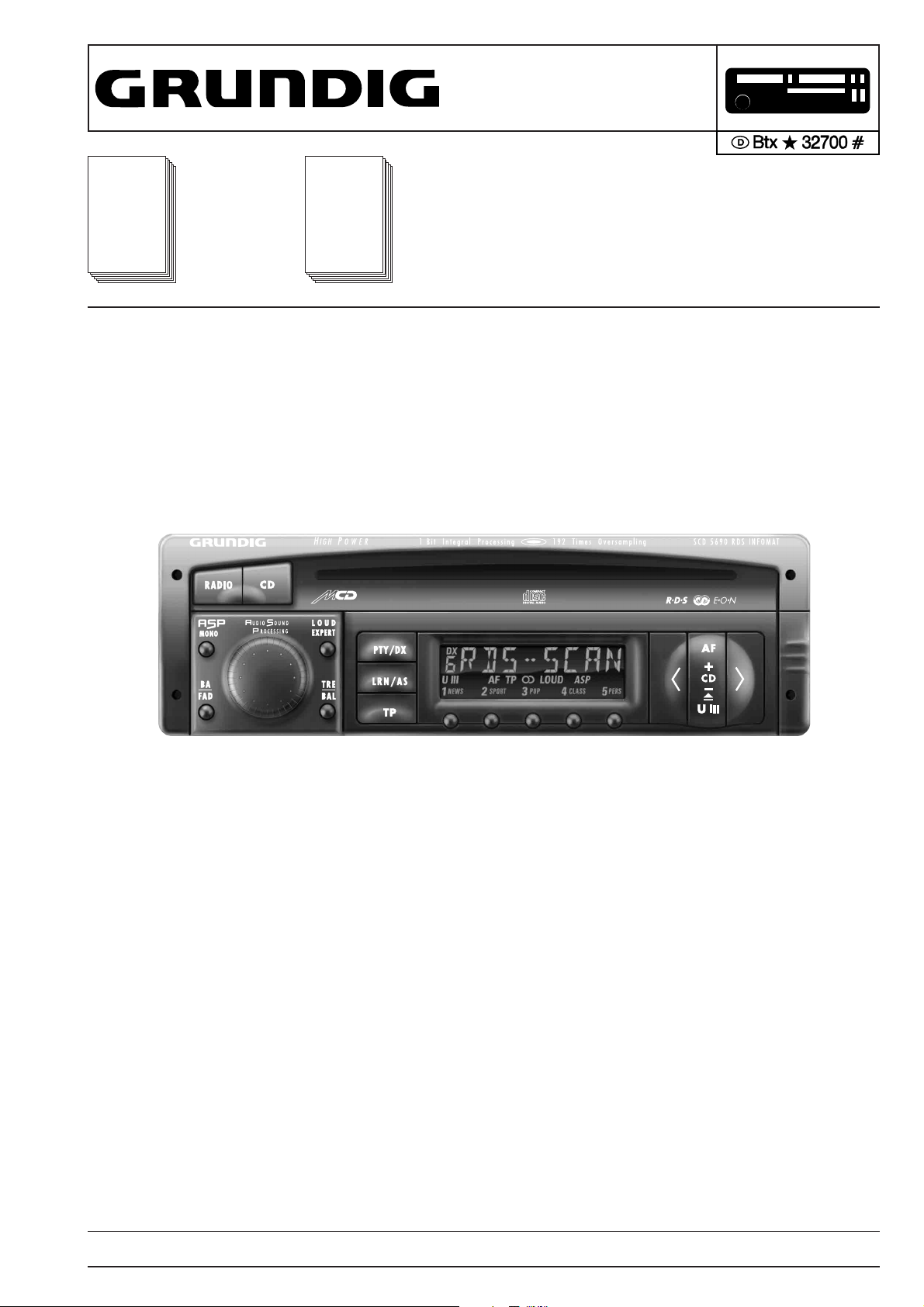
SCD 5390 RDS / SCD 5690 RDS Allgemeiner Teil / General Section
SERVICE MANUAL
Service
Manual
SCD 5390 RDS
SCD 5690 RDS
Sach-Nr./Part No.
72010-749.45
Zusätzlich erforderliche Unterlagen
für den
Komplettservice:
Additionally
required Service
Manuals for the
Complete Service:
Service
Manual
Sicherheit
Safety
Sach-Nr./Part No.
72010-800.00
CHANGER CONTROL
SCD 5390 RDS
SCD 5690 RDS
SCD 5390 RDS (9.18324-8151 / G.HF 17-00)
SCD 5690 RDS (9.18325-8151 / G.HF 44-00)
Änderungen vorbehalten Printed in Germany Service Manual Sach-Nr.
Subject to alteration VK 233 0896 Service Manual Part No. 72010-749.45
GRUNDIG Service 1 - 1
Page 2

Allgemeiner Teil / General Section SCD 5390 RDS / SCD 5690 RDS
Es gelten die Vorschriften und Sicherheitshinweise gemäß dem Service Manual "Sicherheit",
Sach-Nummer 72010-800.00, sowie zusätzlich
die eventuell abweichenden, landesspezifischen
Vorschriften!
D
Inhaltsverzeichnis
Seite
Allgemeiner Teil ............................ 1 - 2 … 1 - 9
Meßgeräte / Meßmittel .............................................................. 1 - 2
Ausbauhinweise ........................................................................ 1 - 3
Bedienhinweise ......................................................................... 1 - 5
Abgleichvorschriften .................... 2 - 1 … 2 - 3
Schaltpläne und
Druckplattenabbildungen ........... 3 - 1 … 3 - 29
Bauteilhinweise ......................................................................... 3 - 1
Schaltpläne:
HF-Teil ................................................................................... 3 - 3
Prozessor-Teil ........................................................................ 3 - 7
Bedienplatte ......................................................................... 3 - 11
CD-Laufwerk ........................................................................ 3 - 13
NF-Teil ................................................................................. 3 - 15
Anschlußplatte ..................................................................... 3 - 19
LCD-Platte ........................................................................... 3 - 21
Druckplattenabbildungen ........................................................ 3 - 23
The regulations and safety instructions shall be
valid as provided by the "Safety" Service Manual,
part number 72010-800.00, as well as the respective national deviations.
GB
Table of Contents
Page
General Section ........................... 1 - 2 … 1 - 13
Test Equipment / Aids ............................................................... 1 - 2
Disassembly Instructions .......................................................... 1 - 3
Operating Hints ......................................................................... 1 - 9
Adjustment Procedures................ 2 - 2 … 2 - 3
Circuit Diagrams
and Layout of PCBs .................... 3 - 1 … 3 - 29
Hints on Components ............................................................... 3 - 1
Circuit Diagrams:
RF Part .................................................................................. 3 - 3
Processor Part ....................................................................... 3 - 7
Operating Board .................................................................. 3 - 11
CD Drive .............................................................................. 3 - 13
AF Part ................................................................................. 3 - 15
Connecting Board ................................................................ 3 - 19
LCD Board ........................................................................... 3 - 21
Layout of PCBs ....................................................................... 3 - 23
Ersatzteillisten und
Explosionszeichnungen ............... 4 - 1 … 4 - 3
Ersatzteilliste SCD 5390 RDS ................................................... 4 - 1
Ersatzteilliste SCD 5690 RDS ................................................... 4 - 2
Allgemeiner Teil
Meßgeräte / Meßmittel
DC-Voltmeter
NF-Voltmeter
Meßsender
Stereocoder
Wobbler
Beachten Sie bitte das GRUNDIG Meßtechnik-Programm, das Sie
unter folgender Adresse erhalten:
GRUNDIG electronics GmbH
Würzburger Str. 150
D-90766 Fürth/Bay
Tel. 0911/703-0, Fax 0911/703-4479
Spare Parts Lists and
Exploded Views ............................. 4 - 1 … 4 - 3
Spare Parts List SCD 5390 RDS .............................................. 4 - 1
Spare Parts List SCD 5690 RDS .............................................. 4 - 2
General Section
Test Equipment / Aids
DC Voltmeter
AF Voltmeter
Test Generator
Stereo Coder
Sweep Generator
Please note the Grundig Catalog “Test and Measuring Equipment”
obtainable from:
GRUNDIG electronics GmbH
Würzburger Str. 150
D-90766 Fürth/Bay
Tel. 0911/703-0, Fax 0911/703-4479
1 - 2 GRUNDIG Service
Page 3
SCD 5390 RDS / SCD 5690 RDS Allgemeiner Teil / General Section
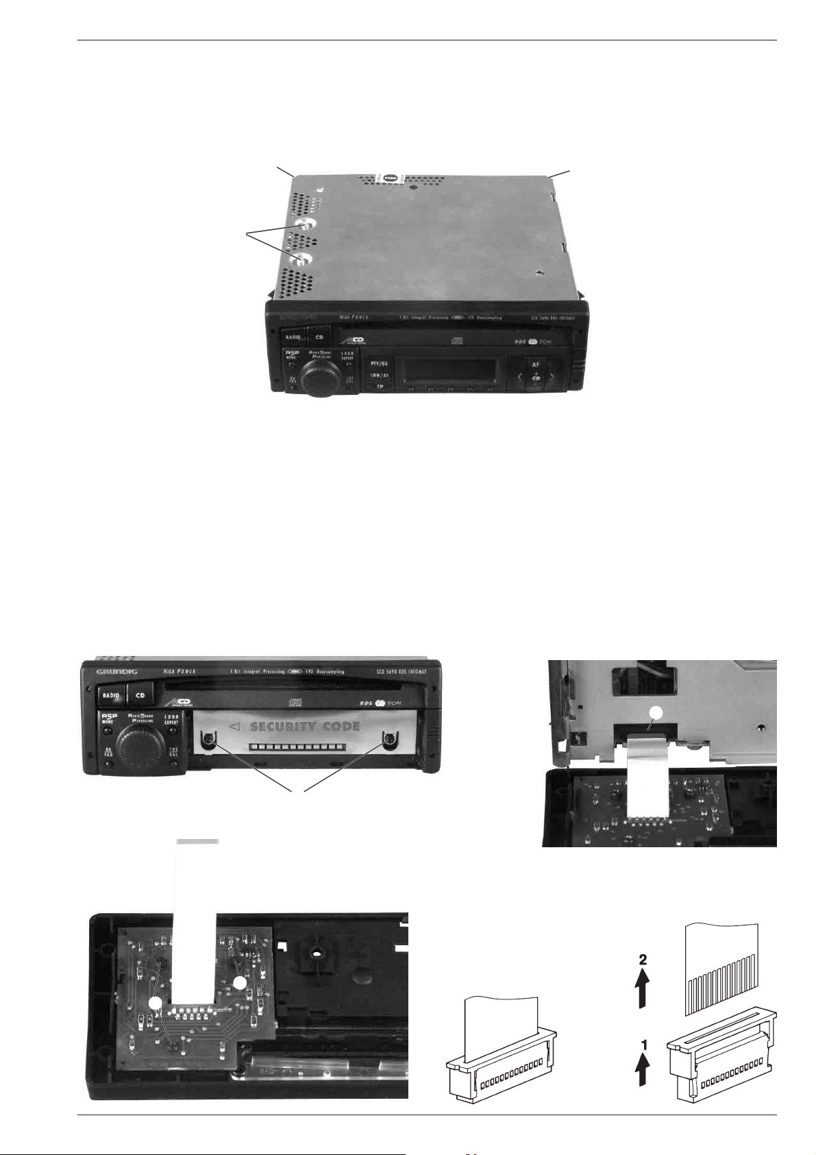
Ausbauhinweise
1. Öffnen des Gehäuses (Fig. 1)
- Die 2 Schrauben A herausschrauben.
- Den Deckel mit einem Schraubendreher an den Punkten B anhebeln.
- Den Deckel abheben.
Fig. 1
B
A
Disassembly Instructions
1. Opening the Cover (Fig. 1)
- Undo the 2 screws A.
- Lift the cover with a screwdriver at the points B.
- Remove the cover.
B
2. Ausbau der Frontblende
- Deckel und Bodenblech abnehmen.
- Das Bedienteil abnehmen und die 2 Schrauben C (Fig. 2) herausschrauben.
- Den Flexprintstecker D öffnen (Fig. 3).
- Die Frontblende abnehmen.
- Zum Zerlegen der Frontblende die 3 Schrauben E herausschrauben (Fig. 4).
Fig. 2
C
Fig. 4
2. Removing the Front Panel
- Remove cover and bottom.
- Remove the operating part and undo the 2 screws C (Fig. 2).
- Disconnect the flexprint connector D (Fig. 3).
- Pull off the front panel.
- To disassemble the font panel undo the 3 screws E (Fig. 4).
Fig. 3
D
Öffnen der Flexprintstecker
Opening the flexprint connectors
E
E
GRUNDIG Service 1 - 3
Page 4
Allgemeiner Teil / General Section SCD 5390 RDS / SCD 5690 RDS
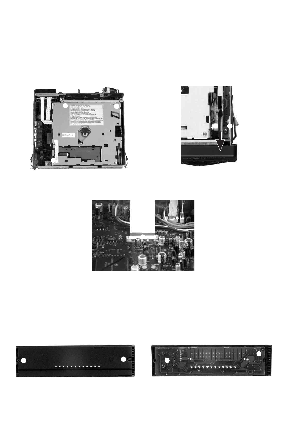
3. Auswerfen der CD bei defektem Laufwerk
- Gehäuse öffnen (Pkt. 1).
- Das Rad F (Fig. 6) in Pfeilrichtung solange drehen, bis die CD
erscheint.
- CD herausziehen.
4. Ausbau des CD-Laufwerks
- Gehäuse öffnen (Pkt. 1).
- Die 3 Schrauben G (Fig. 5) und die Schraube H (Fig. 6) herausschrauben.
- Das CD-Laufwerk anheben und den Flexprintstecker J (Fig. 7)
öffnen.
Fig. 5 Fig. 6
G
G
3. Removing a CD with defective Drive
- Open the cover (para 1).
- Turn the wheel F (Fig. 6) in direction of the arrow until the CD
appears.
- Pull out the CD.
4. Removing the CD Drive
- Open the cover (para 1).
- Undo the 3 screws G (Fig. 5) and the screw H (Fig. 6).
- Lift the CD Drive and open the flexprint connector J (Fig. 7).
G
HF
Fig. 7
J
5. Zerlegen des Bedienteils
- Bedienteil abnehmen.
- Die 2 Schrauben K herausschrauben (Fig. 8).
- Mit einem kleinen Schraubendreher die beiden Teile vorsichtig
auseinanderbiegen.
- Die 3 Schrauben L herausschrauben und die Leiterplatte entnehmen (Fig. 9).
Fig. 8 Fig. 9
5. Disassembling of the Operating Part
- Remove the operating part.
- Undo the 2 screws K (Fig. 8).
- Spread apart the two parts with a small screw driver.
- Undo the 3 screws L and take off the PCB (Fig. 9).
L
K
1 - 4 GRUNDIG Service
K
L
Page 5

SCD 5390 RDS / SCD 5690 RDS Allgemeiner Teil / General Section
GRUNDIG Service 1 - 5
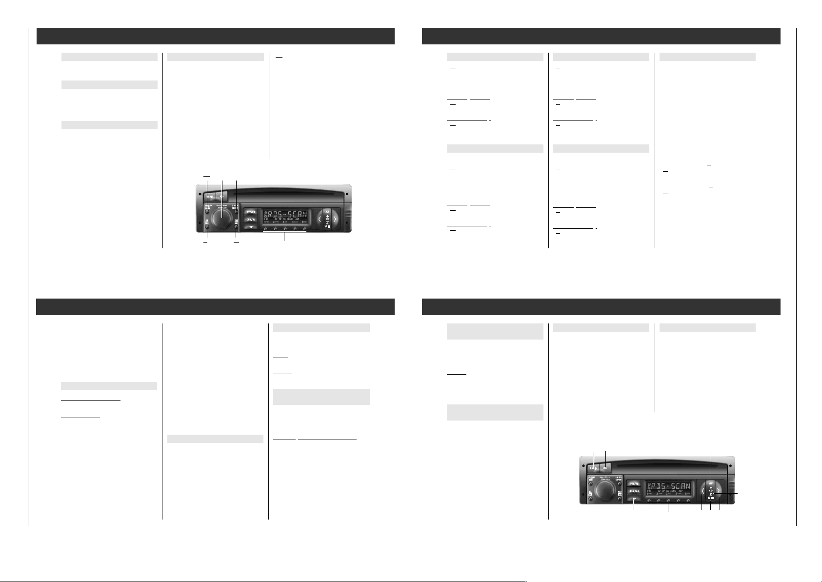
Bedienhinweise Hinweis: Dieses Kapitel enthält Auszüge aus der Bedienungsanleitung. Weitergehende Informationen entnehmen Sie bitte der gerätespezifischen Bedienungsanleitung, deren Sachnummer
Sie in der entsprechenden Ersatzteilliste finden.
Expert
Eine Vielzahl "möglicher" Einstellungen,
ohne den Überblick zu verlieren.
Damit die Bedienung des Autoradios so einfach wie möglich ist, befinden sich eine Vielzahl von Einstellungen, die Sie nur einmal
oder nur gelegentlich brauchen, in einer
zusätzlichen Bedienebene (EXPERT).
Multifunktionstasten
Nachdem Sie eine Programmquelle gewählt
haben, können Sie mit den Multifunktionstasten verschiedene Funktionen bedienen.
Ein- und Ausschalten
– am Autoradio
¢¢
Drehknopf drücken.
– mit dem Zünd-/Anlaßschalter
des Fahrzeugs, wenn das Autoradio vorher
mit dem Zünd-/Anlaßschalter ausgeschaltet
wurde.
Einschalten für max. 1 Stunde
…nachdem Sie Ihr Autoradio mit dem
Zünd-/Anlaßschalter Ihres Fahrzeugs
ausgeschaltet haben:
¢¢
Drehknopf drücken.
Bleibt der Zünd-/Anlaßschalter ausgeschaltet,
schaltet sich das Autoradio nach 1 Stunde
automatisch aus.
Autoradio vorher ausschalten:
¢¢
Drehknopf drücken.
Wiederholtes Einschalten ist möglich.
Phone-Betrieb mit Autotelefon
Anschlußmöglichkeit für Autotelefon oder
Funkgerät.
Stummschaltung (Mute)
Beim Betrieb des Autotelefons bzw. des Funkgerätes ist das Autoradio "stummgeschaltet".
Wenn im Expert Mode die Funktion »Stummschaltung bei Phone-Betrieb« auf
»PHONE IN« geschaltet wurde, wird das
Autoradio beim Betrieb des Telefons/Funkgerätes stummgeschaltet und das Gespräch
über die Lautsprecher des Autoradios wiedergegeben.
Falls das Autoradio vorher ausgeschaltet war,
schaltet es sich bei einem ankommenden
Anruf automatisch ein.
Lautstärke, Bässe, Höhen und Lautstärkeverhältnisse können Sie, während Sie "Laut
Mithören", beliebig einstellen.
í
Achtung bei Automatikantennen!
Ihr Gerät schaltet sich automatisch ein,
wenn ein angeschlossenes Telefon/Funkgerät angerufen wird.
Bitte beachten Sie
CD-Wechsler-Betrieb
CD 1 TO1 1. CD – 1. Titel.
TO1 O1:15 1. Titel – Spielzeit des 1. Titels.
CD SCAN 1.Titel jeder CD für ca.10 Sekun-
den anspielen.
TR RND Titel der CD in zufälliger
Reihenfolge (TRACK RANDOM).
CD HOT CD-Wechsler überhitzt.
MECHANIC CD-Wechsler – Mechanikfehler.
SURFACE CD falsch eingelegt oder
Datenübertragung gestört.
MAGAZINE CD-Magazin fehlt bzw. nicht
eingerastet.
NO CD CD-Magazin leer.
RESET Beenden von
CD SCAN oder TRACK RANDOM.
MUSIC Einstellung für Audio Sound Pro-
cessing
1 CD-Wechsler-Betrieb
TP "Verkehrsfunk"-Bereitschaft
aktiviert.
LOUD Verbesserter Klangeindruck bei
geringer Lautstärke (Loudness).
DX
1
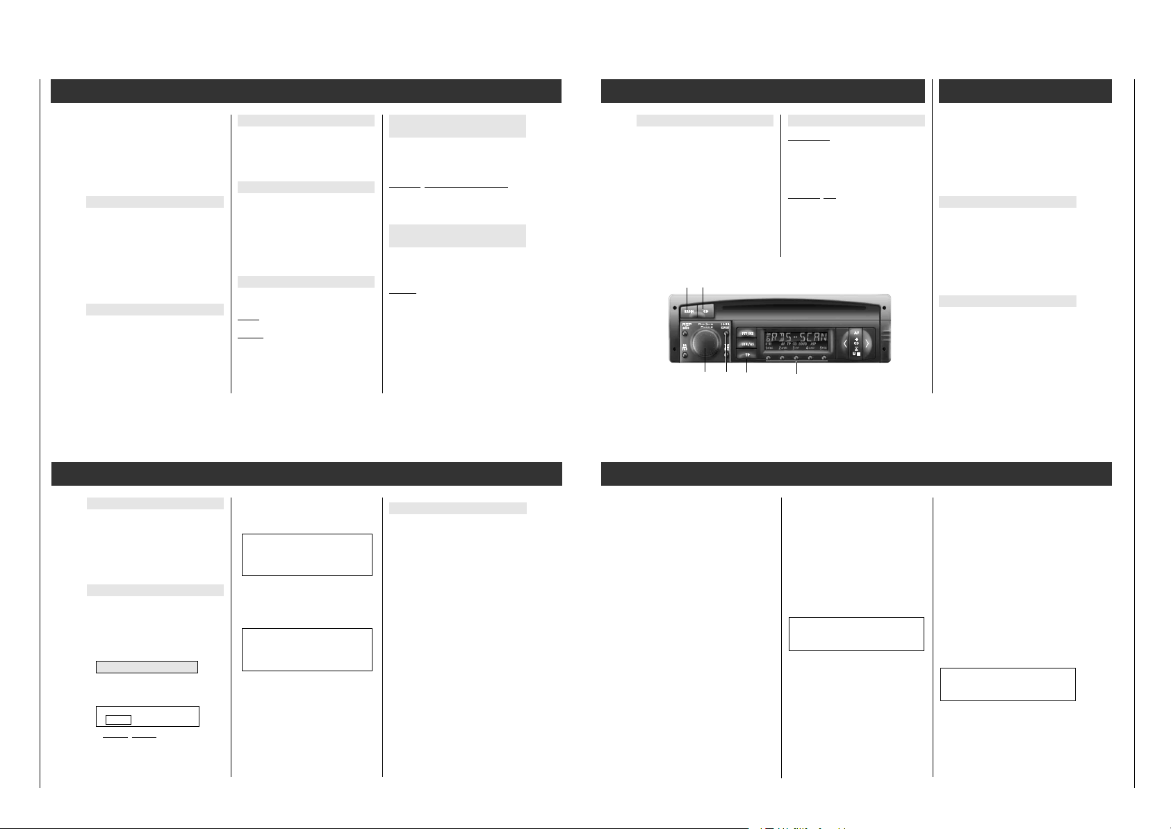
88888888
U III DAB AF TP ɳ LOUD APF ij CR
1
NEWS2 SPORT3 POP4 CLASS5 PERS
Radio
MW Bereich (Mittelwelle).
LW Bereich (Langwelle).
DX Max. Suchlauf-Empfindlichkeit.
LRN RDS-Programme werden im
LEARN-Speicher gespeichert.
RDS SCAN LEARN-Speicher: RDS-Program-
me manuell aufrufen.
AUTOSCAN LEARN-Speicher: RDS-Program-
me automatisch aufrufen.
MUSIC Einstellung für Audio Sound Pro-
cessing
U Bereiche: UI U II UIII.
AF RDS-Programm
mit alternativen Frequenzen und
AF-Wechsel erlaubt.
TP Es werden nur Sender/RDS-Pro-
gramm mit "Verkehrsfunk" eingestellt.
ɳ Stereo-Empfang.
ǵǵ
Das Autoradio wurde manuell auf
Mono geschaltet.
LOUD Verbesserter Klangeindruck bei
geringer Lautstärke (Loudness).
DX
8
88888888
U III DAB AF TP ɳ LOUD APF ij CR
1
NEWS2 SPORT3 POP4 CLASS5 PERS
1. . . 5 Nummern der Stationstasten.
NEWS . . . PTY-Funktionen.
CD-Betrieb
TO1 O 1:15 1. Titel – Abgespielte Zeit des
1.Titels.
TR SCAN Titel der CD werden für ca. 10
Sekunden angespielt.
TR RND Titel der CD werden in zufälliger
Reihenfolge angespielt (TRACK
RANDOM).
RESET Beenden von TR SCAN oder
TR RND.
CD HOT CD-Spieler überhitzt. Lassen Sie
das Gerät abkühlen.
NO CD Keine CD eingelegt.
MECHANIC CD-Spieler – Mechanikfehler.
Surface CD falsch herum eingelegt.
MUSIC Einstellung für Audio Sound Pro-
cessing
TP Verkehrsfunk-Bereitschaft
aktiviert.
LOUD Besserer Klangeindruck bei
geringer Lautstärke (Loudness).
DX
8
88888888
U III DAB AF TP ɳ LOUD APF ij CR
1
NEWS2 SPORT3 POP4 CLASS5 PERS
Display
ROCK M Rockmusik
M.O.R.M Leichte Musik
LIGHT M Leichte klassische Musik
CLASSICS Ernste klassische Musik
OTHER M Musikprogramme die sich nicht
zuordnen lassen (z.B. Folklore)
NO PTY Keine Programmtyp-Kennung
PTY-Programm-Tasten
Die Stationstasten
sind belegt mit den Programmtypen:
1
NEWS,2SPORT, 3POP (mit M.O.R.M)
und
4
CLASSICS (mit LIGHT M).
Die Stationstaste
5
PERS (persönlich) können Sie mit einem
Programmtyp Ihrer Wahl belegen:
1. PTY-Funktion einschalten:
¡
PTY/DX
-Taste kurz drücken.
2.
“
< -Taste oder “> -Taste so oft drücken
bis der gewünschte Programmtyp im Display erscheint.
3. Taste
5
drücken bis der Signalton erklingt.
PTY-Funktion
1. PTY-Funktion einschalten
¡
PTY/DX
-Taste kurz drücken:
zuletzt gewählter Programmtyp im Display.
2. Programmtyp einstellen…
– mit den PTY-Pro
gramm-Tasten
NEWS, SPORT, POP, CLASS oder PERS
Taste kurz drücken:
PTY-Suchlauf startet automatisch zum
nächsten Sender, der den gewählten Programmtyp anbietet, dabei steht » PTY ... «
im Display.
– oder –
“
< -Taste oder “> -Taste kurz drücken
bis der gewünschte Programmtyp im Display erscheint
“
< -Taste oder “> -Taste drücken bis der
Signalton erklingt:
PTY-Suchlauf startet zum nächsten Sender,
der den gewählten Programmtyp anbietet
und zeigt den Programmtyp, z.B. » POP «.
Bietet kein Sender den gewählten
Programmtyp an, hören Sie den zuletzt
eingestellten Sender und die PTY-Funktion
wird verlassen.
3. PTY-Funktion abschalten
¡
PTY/DX
-Taste kurz drücken oder
automatisch nach ca. 10 Sekunden.
Radio
¡
PTY/DX
1– 5
“
<“>
¡
CD
Radio
RDS-Programme mit dem LEARNSpeicher einstellen
Mit einem Tastendruck
können Sie im LEARN-Speicher
bis zu 24 RDS-Programme speichern!
Die gespeicherten RDS-Programme
können Sie manuell (RDS–SCAN) oder automatisch (AUTOSCAN) nacheinander aufrufen.
LEARN-Speicher belegen
Bereich: U l, U ll oder U lll.
¡
LRN/AS
-Taste kurz drücken:
RDS-Programme (max. 24) Ihres Empfangsbereiches werden gespeichert;
»LRN ...« im Display.
Anschließend hören Sie das bestempfangbare RDS-Programm oder
nur "RDS-Programme mit Verkehrsfunk"
aufrufen, wenn
“
TP
-Taste "aktiviert".
Ein/Aus:
“
TP
-Taste drücken.
– manuell
(RDS–SCAN)
“
< -Taste oder “> -Taste
(wiederholt) kurz drücken:
»RDS SCAN« erscheint im Display.
Anschließend hören Sie das nächste RDSProgramm.
– automatisch (AUTOSCAN)
¡
RADIO
-Taste drücken bis der Signalton
erklingt.
»AUTOSCAN« erscheint im Display.
Anschließend werden RDS-Programme nacheinander für ca. 10 Sekunden aufgerufen.
Soll der aufgerufene Sender hörbar bleiben:
¡
RADIO
-Taste kurz drücken;
»RESET« erscheint kurz im Display.
Automatischer Senderspeicher
Autostore
Die 5 stärksten Sender des gewählten Bereiches Ihres Empfangsgebietes speichern Sie
automatisch auf den Stationstasten
1 bis 4
im gewählten Bereich.
Bereich wählen: U l, U ll, U lll, MW oder LW.
¡
LRN/AS
-Taste drücken bis der Signalton
erklingt.
Im Display erscheint » AS « und die
Frequenzanzeige läuft durch.
Anschließend hören Sie das bestempfangbare Programm.
Programmtypen
Voraussetzung
Rundfunkanstalten bieten im UKW-Bereich
(Ul, U ll, Ulll) den Service "Programmtypen"
(PTY) an.
Programmtypen
Die angebotenen Programmtypen einer Rundfunkanstalt können je nach gesendetem Programm wechseln.
NEWS Nachrichten und Aktuelles
AFFAIRS Politik und Zeitgeschehen
INFO Spezielle Wortprogramme
SPORT Sportsendungen
EDUCATE Lernen und Weiterbildung
DRAMA Hörspiel und Literatur
CULTURE Kultur, Kirche und Gesellschaft
SCIENCE Wissenschaft
VARIED Unterhaltendes Wort
POP Popmusik (Hits und Schlager)
Page 6
Allgemeiner Teil / General Section SCD 5390 RDS / SCD 5690 RDS
1 - 6 GRUNDIG Service
CD-Betrieb
íAuf Multimedia CD´s sind neben
Audiotracks auch Datentracks aufgezeichnet. Spielen Sie eine solche CD trotz der
Warnhinweise ab, kann es zu Rauschen in
verkehrsgefährdender Lautstärke kommen. Zudem können Endstufen und Lautsprecher beschädigt werden.
Programmquelle CD wählen
CD ins CD-Fach einschieben.
Im Display erscheint »T01 00:00«. – oder –
CD ist im CD-Fach:
¡
CD
-Taste so oft drücken bis z.B.
»T01 00:00« im Display erscheint.
Wenn Sie die CD nicht vollständig einziehen
lassen erscheint im Display »NO CD«.
Durch erneutes Einschieben einer CD bzw.
durch Drücken der
¡
CD
-Taste können Sie
diesen Zustand verlassen.
Mit der
¡
CD
-Taste können Sie zwischen
dem eingebauten CD-Spieler und einem angeschlossenem CD-Wechsler umschalten.
Wird der eingebaute CD-Spieler angewählt,
erscheint im Display z. B. »T01 00:00«.
Wird der CD-Wechsler angewählt, erscheint
im Display »MCD 1« und dann z. B.
»1 CD1 T01« oder gleich z. B. »1 CD1 T01«
í Achtung bei Automatikantennen!
Ihr Gerät schaltet sich automatisch ein,
wenn Sie eine CD einschieben.
Dadurch wird auch Ihre Automatikantenne
ausgefahren! Beachten Sie dazu auch den
Hinweis auf Seite 3!
Titel wählen bzw. wiederholen
“
> -Taste: nächste Titel
“
< -Taste: vorherige Titel bzw.
den Titel, den Sie hören, wiederholen.
Tasten (so oft) kurz drücken, bis die Nummer
des gewünschten Titels im Display erscheint.
Vorlauf und Rücklauf
Titel im "Schnelldurchgang" mit
reduzierter Lautstärke hören:
Vorlauf
:
“
> -Taste drücken und gedrückt
halten.
Rücklauf
:
“
< -Taste drücken und gedrückt
halten.
Titel der CD für ca. 10 Sekunden
anspielen (TRACK SCAN)
¡
CD
-Taste drücken, bis der Signalton
erklingt:
»TR SCAN« erscheint kurz im Display.
Soll der an
gespielte Titel hörbar bleiben:
¡
CD
-Taste kurz drücken:
»RESET« erscheint kurz im Display.
Titel der CD in zufälliger Reihenfolge
(TRACK RANDOM)
¡
U III
-Taste drücken, bis der Signalton
erklingt:
»TR RND« erscheint kurz im Display.
Beenden:
¡
U III
-Taste drückenbis der Signalton
erklingt:
»RESET« erscheint kurz im Display.
Verkehrsfunk-Durchsagen während
CD-Wiedergabe zulassen
TP einschalten
“
TP
-Taste kurz drücken:
»TP« erscheint im Display.
TP ausschalten
“
TP
-Taste kurz drücken:
»TP« erlischt im Display.
CD-Betrieb beenden
Wählen Sie durch kurzes Drücken der
¡
CD
-Taste oder der
¡
RADIO
-Taste eine
andere Quelle an, oder lassen Sie die CD ausschieben.
oder
eine der Stationstasten
12345
kurz drücken.
CD ausschieben
Drücken Sie kurz die
¡
U III
-Taste. Die CD
wird ausgeschoben.
Wird die ausgeschobene CD nicht innerhalb
von 15 Sekunden entnommen, wird sie aus
Sicherheitsgründen wieder eingezogen.
Soll die CD jetzt ausgeschoben werden, muß
zuerst die
¡
CD
-Taste und dann die
¡
U III
-Taste betätigt werden.
“
TP
1– 5
“
<
¡
U III
“
>
¡
RADIO¡CD
¡
CD
+
CD-Betrieb
¡
CD
–
Verstärker
ASP (Audio Sound Processing)
Mit Audio Sound Processing können Sie zwischen verschiedenen Raumklangeffekten
wählen.
Die ersten vier Stationstasten sind mit den
Klangarten »MOVIE«, »DISCO«, »VOICE« und
»MUSIC« belegt.
Mit der Stationstaste
5
wird die
ASP-Funktion verlassen.
Im Display erscheint »ASP OFF«.
“
ASP
MONO -Taste kurz drücken.
Mit den Stationstasten
1 bis 4können Sie
eine Klangart einstellen.
Im Display erscheint z.B. »MUSIC«.
íBei Mono-Sendungen bzw. manueller
Monoeinstellung ist nur in Stellung
»VOICE« eine Klangveränderung wahrzunehmen.
Wenn Sie sich in einem schlecht versorgten
Empfangsgebiet aufhalten, können durch die
ASP-Funktion Empfangsstörungen verstärkt
hörbar werden.
In diesem Fall sollten Sie die ASP-Funktion
ausschalten.
Ein- und Ausschalten am Autoradio
¢¢
Drehknopf kurz drücken.
Lautstärke (Volume)
¢¢
Drehknopf drehen:
Im Display erscheint:
»VOL 00« … »VOL 46«
LOUD (Loudness)
Loudness sorgt für besseren Klangeindruck
bei geringer Lautstärke.
“
LOUD
EXPERT
-Taste kurz drücken.
Im Display erscheint: »LOUD«
bei eingeschalteter Loudness-Funktion.
“
BA
FAD
“
TRE
BAL
1– 5
“
ASP
MONO
¢¢
“
LOUD
EXPERT
Verstärker
Klangspeicher
Sie können auf den Stationstasten 1 bis 4
4 verschiedene Klang- und
Geometrie-Einstellungen speichern.
Einstellungen speichern
Stellen Sie Bass, Höhe, Fader, Balance und
Loudness ein.
Drücken Sie, während Sie sich im
Einstellmodus befinden, z.B. die
Stationstaste
1, bis Sie den Signalton hören.
Im Display erscheint:
»SOUND 1«.
Die eingestellten Werte sind gespeichert.
Einstellungen aufrufen
Drücken Sie die Taste
“
BA
FAD oder die Taste
“
TRE
BAL und dann z.B. die
Stationstaste
1.
Drücken Sie die Taste
“
B
A
FAD oder die Taste
“
TR
E
BAL und dann die Stationstaste
5
, werden
die Mittelstellungen eingeschaltet.
Im Display erscheint:
»LINEAR«.
Bässe BASS
“
BA
FAD -Taste kurz drücken.
¢¢
Drehknopf drehen:
Im Display erscheint:
»BASS -14«…»BASS 00«…»BASS + 14«
Einstellun
g beenden:
“
BA
FAD -Taste 2mal kurz drücken oder nach
ca.10 Sekunden automatisch.
Sofort Mittelstellun
g:
“
BA
FAD -Taste drücken bis der Signalton
erklingt.
Lautstärkeverhältnis FAD (Fader)
Lautsprecher vorne ɫ hinten
“
BA
FAD -Taste 2mal kurz drücken.
¢¢
Drehknopf drehen:
Im Display erscheint:
»FAD R31« … »FAD R - - F« … »FAD F31«
Hinten/Rear … Mittelstellun g … Vorne/Front
Einstellun
g beenden:
“
BA
FAD -Taste kurz drücken oder nach
ca.10 Sekunden automatisch.
Sofort Mittelstellun
g:
“
BA
FAD -Taste drücken bis der Signalton
erklingt.
Höhen TRE (Treble)
“
TRE
BAL -Taste kurz drücken.
¢¢
Drehknopf drehen.
Im Display erscheint:
»TREB - 14«…»TREB 00«…»TREB + 14«
Einstellun
g beenden:
“
TRE
BAL -Taste 2mal kurz drücken oder nach
ca.10 Sekunden automatisch.
Sofort Mittelstellun
g:
“
TRE
BAL -Taste drücken bis der Signalton
erklingt.
Lautstärkeverhältnis BAL (Balance)
Lautsprecher links ɫrechts
“
TRE
BAL -Taste 2mal kurz drücken.
¢¢
Drehknopf drehen:
Im Display erscheint:
»BAL L31«…»BAL L - - R«…»BAL R31«
Links Mittelstellung Rechts
Einstellun
g beenden:
“
TRE
BAL -Taste kurz drücken oder nach
ca.10 Sekunden automatisch.
Sofort Mittelstellun
g:
“
TRE
BAL -Taste drücken bis der Signalton
erklingt.
Page 7
SCD 5390 RDS / SCD 5690 RDS Allgemeiner Teil / General Section
GRUNDIG Service 1 - 7
Mögliche Einstellungen 1…ßZ
Anzeige im Display: » ...... «
1 Display-Kontrast ändern
» LCD 25 « (00 … 63), je nach Einbaulage
des Autoradios einstellen.
Optimale Einstellung bei
"Dunkelheit".
2 Display-Farbe
Vario-Color (von grün bis rot)
» COL 25 « (00 … 53).
3 Security-Leuchtanzeige (Ein/Aus)
» BLK ON « CD-Taste blinkt bei ausgeschal-
tetem Gerät und ausgeschalteter
Beleuchtung und Zündung.
» BLK OFF « CD-Taste blinkt nicht.
4 Signalton (Ein/Aus)
» BEEP ON « Bei Funktionswechsel erklingt
ein Signalton.
» BEEP OFF « Bei Funktionswechsel erklingt
kein Signalton.
3. Einstellung "aktivieren"
“
LOUD
EXPERT
-Taste kurz drücken:
»
E « erscheint im Display
4. Einstellung verändern
Stellen Sie mit dem
¢¢
Drehknopf
z.B. den gewünschten Kontrast ein.
Im Display erscheint z. B.:
5. Einstellung beenden
“
LOUD
EXPERT
-Taste kurz drücken:
»
E « erlischt im Display
6. Nächste "Einstellung wählen"
(Punkt 2. bis 5. wiederholen)
7. EXPERT ausschalten
“
LOUD
EXPERT
-Taste drücken bis der Signalton
erklingt.
DX
E
LCD88853
U III DAB AF TP ɳ LOUD APF ij CR
1
NEWS2 SPORT3 POP4 CLASS5 PERS
DX
E
LCD88825
U III DAB AF TP ɳ LOUD APF ij CR
1
NEWS2 SPORT3 POP4 CLASS5 PERS
EXPERT
Eine Vielzahl "möglicher" Einstellungen
Damit die Bedienung des Autoradios so
einfach wie möglich ist, befinden sich eine
Vielzahl von Einstellungen, die Sie nur einmal
oder nur gelegentlich brauchen, in einer
zusätzlichen Bedienebene (EXPERT).
Einstellen
1. EXPERT einschalten
“
LOUD
EXPERT
-Taste drücken bis der Signalton
erklingt.
2. Einstellung wählen
Wählen Sie aus
die Einstellung, die Sie überprüfen, bzw.
verändern wollen.
Beispiel:
¢¢
Drehknopf drehen
bis die gewünschte
Einstellung » LCD 25 « im Display
erscheint.
1 Display-Kontrast ändern
Mögliche Einstellungen
1…ßZ
EXPERT Einstellungen
LCD 25
9 CD-Eingangsempfindlichkeit
Anpassen eines CD-Spielers:
» MCD LOW « niedrig
» MCD MID « mittel (z. B. MCD 30)
» MCD HIGH « hoch
ßI Lautstärke-Begrenzung beim Einschalten
» ONVOL - - «: keine Begrenzung oder
» ONVOL 35 «: max. Lautstärke, z.B. 20
(- - … 11 … 35).
Die Lautstärke wird nur begrenzt, wenn die
Lautstärke beim Ausschalten des Auto-
radios größer als der eingestellte Wert ist!
ß? Mindestlautstärke für Verkehrsfunk-
Durchsagen
» TA VOL 16 « (5 … 35)
í Aus Gründen der Verkehrssicherheit
sollte die Durchsagelautstärke nicht zu
hoch eingestellt werden!
8 Stummschaltung bei Phone-Betrieb
mit Autotelefon
» PHONE OFF « keine Auswertung des
Telefonanschlusses
» PHONE ON « Das Autoradio wird bei einem
Telefonanruf automatisch
stummgeschaltet.
» PHONE IN « Das Autoradio wird bei einem
Telefonanruf automatisch
eingeschaltet und das
Gespräch wird über die Lautsprecher wiedergegeben.
Wenn Sie während eines Telefongesprächs
die Klang- und Geometrieeinstellungen verändern, bleiben diese für das nächste Telefongespräch gespeichert.
Beim Zurückschalten auf Radio-Betrieb wird
auf die vorherigen Klang- und Geometrieeinstellungen geschaltet.
í Lesen Sie bitte dazu die Hinweise im
Kapitel »Achtung bei Automatikantennen« auf Seite 3!
5 Autom. LEARN (Radio-Betrieb)
Wenn Sie sich in einem Empfangsgebiet
aufhalten, in denen Sie "RDS-Programme
mit Verkehrsfunk" schlecht empfangen,
können Sie den "autom. LEARN (LRN) im
Radio-Betrieb" verhindern.
» LRN ON «: autom. LEARN
» LRN OFF «: kein autom. LEARN bei einge-
stellten Lautstärken größer
» VOL 4 «.
6 Autom. Wechsel des Regionalprogramms
Wenn ein RDS-Programm aus verschiede-
nen Regionalsendungen besteht, kann es
vorkommen, daß Ihr Autoradio aufgrund
des Empfangsgebietes zwischen verschie-
denen Regionalsendungen wechselt.
» REG ON « autom. Wechsel des Regional-
programms ist möglich.
» REG OFF « kein Wechsel auf ein anderes
Regionalprogramm.
7 Ein- und Ausschalten mit dem
Zünd-/Anlaßschalter
» IGN ON « Sie können das Autoradio mit
dem Zünd-/Anlaßschalter ausund einschalten.
»IGN OFF « Ein- und Ausschalten nur mit
dem
¢¢
Drehknopf.
EXPERT
íAuf Multimedia CD´s sind neben
Audiotracks auch Datentracks aufgezeichnet. Spielen Sie eine solche CD trotz der
Warnhinweise ab, kann es zu Rauschen in
verkehrsgefährdender Lautstärke kommen. Zudem können Endstufen und Lautsprecher beschädigt werden.
Programmquelle CD-Wechsler wählen
¡
CD
-Taste drücken.
Im Display erscheint z.B.:
» MCD 1 «: wenn vorher der interne CD-
Spieler angewählt war.
» CD 1 TO1 «: 1. CD - 1. Titel
» TO1 O1:15 «: 1. Titel - Spielzeit des 1. Titels
» TR RND «: "Titel der CD in
zufälliger Reihenfolge".
Display (Anzeige) umschalten
¡
CD
+
-Taste drücken bis der Signalton
erklingt: z.B.
» CD 1 TO1 «: 1. CD - 1. Titel bzw.
» TO1 O1:15 «: 1. Titel - Spielzeit des 1.
Titels.
CD wählen
¡
CD
+
-Taste bzw.
¡
CD
–
-Taste (wiederholt) kurz drücken,
bis die Nummer der gewünschten CD
im Display erscheint.
Titel wählen bzw. wiederholen
Tasten (wiederholt) kurz drücken, bis die
Nummer des gewünschten Titels im Display
erscheint.
“
> -Taste: nächste(r) Titel
“
< -Taste: vorherige(r) Titel bzw.
den Titel, den Sie hören,
wiederholen.
Vorlauf und Rücklauf
Titel im "Schnelldurchgang" mit
reduzierter Lautstärke hören:
Vorlauf
:
“
> -Taste drücken und gedrückt
halten.
Rücklauf
:
“
< -Taste drücken und gedrückt
halten.
1. Titel jeder CD für ca.10 Sekunden
anspielen (CD SCAN)
¡
CD
-Taste drücken bis der Signalton
erklingt:
» CD SCAN « erscheint kurz im Display.
Soll der an
gespielte Titel hörbar bleiben:
¡
CD
-Taste kurz drücken:
» RESET « erscheint kurz im Display.
Titel der CD in zufälliger Reihenfolge
(TRACK RANDOM)
¡
CD
–
-Taste drücken bis der Signalton
erklingt:
» TR RND « erscheint kurz im Display.
Beenden:
¡
CD
–
-Taste drücken bis der Signalton
erklingt:
» RESET « erscheint kurz im Display.
* Welcher "Grundig CD-Wechsler" geeignet
ist, sagt Ihnen Ihr Fachhändler.
Compact Disc (CD) mit »GRUNDIG CD-Wechsler«*
Verkehrsfunk-Durchsagen
TP einschalten
“
TP
-Taste kurz drücken
» TP « erscheint im Display.
TP ausschalten
“
TP
-Taste kurz drücken
» TP « erlischt im Display.
CD-Wechsler-Betrieb beenden
Radio-Betrieb:
¡
RADIO
-Taste drücken
oder
eine der Stationstasten
12345
kurz drücken.
CD-Wieder
gabe:
¡
CD
-Taste drücken bzw. CD ins
CD-Fach einschieben.
íAuf Multimedia CD´s sind neben
Audiotracks auch Datentracks aufgezeichnet. Spielen Sie eine solche CD trotz der
Warnhinweise ab, kann es zu Rauschen in
verkehrsgefährdender Lautstärke kommen. Zudem können Endstufen und Lautsprecher beschädigt werden.
CD- oder DAT-Spieler anschließen
CD = Compact Disc (ohne CD-Wechsler)
DAT = Digital Audio Tape
Haben Sie keinen CD-Wechsler angeschlossen, können Sie einen CD- oder DAT-Spieler
mit geeignetem Verbindungskabel an das
Autoradio anschließen (C13 mit Masse
verbinden).
CD- oder DAT-Betrieb einschalten
Programmquelle CD wählen:
¡
CD
-Taste drücken, im Display » AUX «.
¢¢
“
LOUD
EXPERT
“
TP
1– 2
¡
RADIO¡CD
Compact Disc (CD) mit »GRUNDIG CD-Wechsler«
CD- oder DAT-Betrieb
Page 8
Allgemeiner Teil / General Section SCD 5390 RDS / SCD 5690 RDS
1 - 8 GRUNDIG Service
Einbaumaterial und Zubehör
Welches Einbaumaterial Sie benötigen und
was es an Zubehör gibt, sagt Ihnen Ihr Fachhändler.
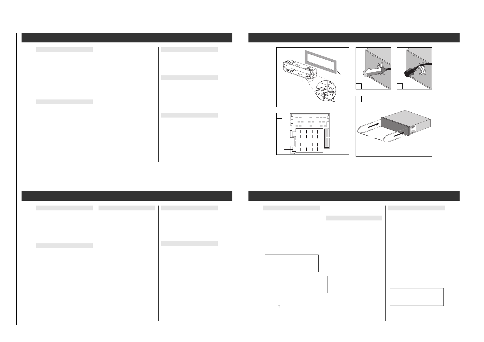
Einbaurahmen einsetzen
Abbildung o
– Einbaurahmen b in den Geräte-Ausschnitt a
des Fahrzeugs einsetzen.
– Schränklappen c hinter dem Geräte-Aus-
schnitt a nach Bedarf (je nach Fahrzeugtyp)
aufbiegen.
Bei Fahrzeugen der Firma VW/Audi, ab
Modelljahr 1991: Messerkontakt A7 auf keinen Fall an den S-Kontakt (Versorgungsstecker PIN 4 – Kabel braun/rot) des Fahrzeugs anschließen.
Die Abbildungen o – azum Text befinden sich am Anfang des Heftes.
Codierung deaktivieren
Z.B. vor dem Ausbau des Autoradios:
1. Expert-Mode ist eingeschaltet und
» SAFE « erscheint im Display.
Aktivieren Sie die Einstellung.
Im Display erscheint »
E 1 - - - - «
2. Code-Nr. (siehe Identity Card), wie im
Kapitel "Codierung aktivieren" beschrieben,
eingeben.
3. Code-Nr. bestätigen:
“
LOUD
EXPERT
-Taste kurz drücken, im Display
erscheint » CODE «.
Nach ca. 3 Sekunden spielt das Radio.
Die Codierun
g ist nicht mehr aktiviert!
Falsche Code-Nr. ein
gegeben:
» SAFE « bleibt im Display stehen, das Radio
spielt nicht.
Beginnen Sie nochmals. Beachten Sie die
"Wartezeiten" zwischen
den Versuchen.
Wiederinbetriebnahme
Das Autoradio ist elektronisch blockiert, nachdem es von der Autobatterie (bzw. Dauerplus
Klemme 30) Ihres Fahrzeugs getrennt war,
z.B. nach dem Herausnehmen des Gerätes.
1. Autoradio einschalten:
Im Display erscheint » SAFE «.
Nach ca. 3 Sekunden erscheint
» I - - - - « im Display.
2. Code-Nr. (siehe Identity Card), wie im
Kapitel "Codierung aktivieren" beschrieben,
eingeben.
3. Code-Nr. bestätigen:
“
LOUD
EXPERT
-Taste kurz drücken, im Display
erscheint » SAFE «.
Nach ca. 3 Sekunden spielt das Radio.
Falsche Code-Nr. ein
ge
geben:
» SAFE « bleibt im Display stehen, das
Radio spielt nicht.
Beginnen Sie nochmals.
Beachten Sie die "Wartezeiten" zwischen
den Versuchen.
Codierung
Ein- und Ausbau
A1 SCV-Anschluß (+)
für "Geschwindigkeitsabhängige Lautstärkeregelung".
Lautsprecher
Messerkontakte B: Abbildung +
Maximale Ausgangsleistung
an 4Ω-Lautsprechern:
Spitzenleistung ________________ 4 x 50 W
Sinusleistung, DIN 45324 ________ 4 x 25 W
Frontlautsprecher Hecklautsprecher
B3 rechts +B1rechts +
B4 rechts –B2rechts –
B5 links +B7links +
B6 links –B8links –
í
Lautsprecheranschlüsse nicht elektrisch miteinander verbinden und nicht
auf Masse legen!
A4 +12 V Zündspannung
An Klemme 15
bzw. Klemme 30 des Fahr-
zeugs anschließen:
– Klemme 15
, wenn Sie das Autoradio mit
dem Zünd-/Anlaßschalter ein- und ausschalten wollen.
– Klemme 30
, wenn Sie das Autoradio nicht
mit dem Zünd-/Anlaßschalter ein- und ausschalten wollen.
A2 Phone-Anschluß (Mute)
für Autotelefon oder Funkgerät:
Das Autoradio ist "stummgeschaltet" beim
Betrieb des angeschlossenen Autotelefons
oder des Funkgerätes. Der Messerkontakt A2
soll dabei vom Mute-Ausgang des
Telefons/Funkgerätes auf Masse gelegt werden!
í
Achtung bei Automatikantennen!
Ihr Gerät schaltet sich automatisch ein,
wenn ein angeschlossenes Telefon/Funkgerät angerufen wird.
Versorgungsspannungen
Messerkontakte A: Abbildung +
A8 – Betriebsspannung (Masse)
An Klemme 31
(Masse) des Fahrzeugs
anschließen.
A7 +12 V Betriebsspannung
An Klemme 30
(Dauerplus) des Fahrzeugs
anschließen.
A6 Beleuchtung des Autoradios
Messerkontakt A6an Klemme 58 des Fahrzeugs anschließen:
Die Beleuchtung des Autoradios kann bei eingeschaltetem Fahrlicht geregelt werden.
Messerkontakt A6 nicht angeschlossen:
Die Helligkeit der Beleuchtung wird nicht verändert.
A5 +12 V Schaltspannung (max. 0,5 A)
am Messerkontakt A 5 bei eingeschaltetem
Autoradio.
Für Automatikantenne (Aus-/Einfahren),
Antennenverstärker (Betriebsspannung) usw.
Ein- und Ausbau
Der Gesamtaufbau des Autoradios gewährleistet wartungsfreien Betrieb über lange Zeit.
Sollte eine Störung auftreten,
wenden Sie sich bitte an Ihren Fachhändler.
Auf Ihren Wunsch kann Ihr Fachhändler in der
Bundesrepublik Deutschland als Serviceleistung Grundig Autoradios im Falle eines
Defektes durch werksgeprüfte Austauschgeräte ersetzen.
Bitte beachten Sie
,
daß Voraussetzung für die Teilnahme Ihres
Fachhändlers an diesem Austauschsystem das
unverletzte Garantiesiegel am Autoradio ist.
Die Frontblende des Autoradios nur mit
einem weichen, staubbindenden und antistatischen Lappen reinigen. Polier- und Reinigungsmittel könnten die Oberfläche der Blende beschädigen.
Akustiksystem
Sie können die Bässe und die Höhen der hinteren und der vorderen Lautsprecher getrennt
einstellen.
Den Einstellbereich von –3 bis +3 können Sie
mit dem
¢¢
Drehknopf verändern.
ßQ Bässe – Lautsprecher vorne
»BAS F 0« (F = Front/vorne)
ßW Bässe – Lautsprecher hinten
»BAS R 0« (R = Rear/hinten)
ßE Höhen – Lautsprecher vorne
»TRE F 0« (F = Front/vorne)
ßR Höhen – Lautsprecher hinten
»TRE R 0« (R = Rear/hinten)
ßT Ein-/Ausschaltverzögerung für ange-
schlossenen Booster
(Schaltspannung für Booster = Kontakt C6)
» BDLY ... « (O6 … 99)
Bei "Schaltgeräuschen": eingestellten Wert
erhöhen oder erniedrigen bis Schaltgeräusche nicht mehr hörbar.
ßZ Codierung aktivieren
Erscheint » CODE « im Display, ist die
Codierung nicht aktiviert.
Erscheint » SAFE « im Display, ist die
Codierung aktiviert.
ß` Geschwindigkeitsabhängige Lautstärke
» SCVOL 124 « (- - … 144)
Einstellung nur möglich, wenn am SCVAnschluß (A1) ein geschwindigkeitsabhän-
giges Signal steht.
» SCVOL - - « : SCV ausgeschaltet
» SCVOL 144 « : Maximale Wirkung
Einstellun
g:
1. Fahrzeug steht, Motor läuft:
Mit dem
¢¢
Drehknopf die gewünschte
Lautstärke einstellen.
2. EXPERT-Einstellung vorbereiten:
“
LOUD
EXPERT
-Taste drücken bis der Signalton
erklingt.
¢¢
Drehknopf drehen bis
» SCVOL ...« im Display erscheint.
“
LOUD
EXPERT
-Taste kurz drücken:
»
E « erscheint im Display
3. Bei höherer Geschwindigkeit:
Mit dem
¢¢
Drehknopf die gewünschte
Lautstärke einstellen,
z.B. » SCVOL 124 « im Display.
“
LOUD
EXPERT
-Taste drücken bis der Signalton
erklingt.
í Aus Gründen der Verkehrssicherheit
sollte die folgende Einstellung durch den
Beifahrer erfolgen!
EXPERT
Wartung und Pflege
Wartezeiten
Damit die "Wiederinbetriebnahme" bzw.
"Codierung deaktivieren"
nicht durch Aus
probieren möglich ist,
sind zwischen den Versuchen Wartezeiten
vorgesehen. In diesen Zeiten ist das Autoradio
für alle Eingaben gesperrt.
Während der Wartezeit
muß das Autoradio nicht eingeschaltet sein.
So lange » SAFE « im Display steht, ist die
Wartezeit noch nicht abgelaufen.
Die Wartezeit ist zu Ende, wenn die Zahl des
nächsten Versuchs im Display zu sehen ist,
z.B. » 2 - - - - «.
Die Tabelle zeigt
die Wartezeiten
zwischen den
einzelnen
Versuchen.
Wartezeit nach
dem 7. Versuch
immer
24 Stunden!
Nach dem 6.
Versuch empfiehlt es sich, "Wiederinbetriebnahme" bzw. "Codierung deaktivieren" von
einem Fachhändler durchführen zu lassen.
Codierung aktivieren
1. Expert-Mode ist eingeschaltet und
» CODE « erscheint im Display.
Aktivieren Sie die Einstellung:
“
LOUD
EXPERT
-Taste kurz drücken
Im Display erscheint »
E - - - - «
2. Code-Nr. (siehe Identity Card) eingeben:
Tasten
1– 4
wiederholt drücken bis
Code-Nr. im Display erscheint.
Beispiel: 1703 Display:
Taste
1
11 x kurz drücken >1 - - -<
Taste
2
17 x kurz drücken >1 7 - -<
Taste
3
10 x kurz drücken >1 7 0 -<
Taste
4
13 x kurz drücken >1 7 0 3<
Bei längerem Drücken wird die jeweilige Ziffer
rückwärts gezählt.
3. Code-Nr. bestätigen:
“
LOUD
EXPERT
-Taste kurz drücken, im Display
erscheint » SAFE «.
Die Codierun
g ist aktiviert!
Codierung
Ihre persönliche Code-Nummer befindet sich
auf der Identity Card des Autoradios.
Die Codierun
g ist ab Werk nicht aktiviert.
Wenn Sie die Codierung Ihres Autoradios
"Aktiviert" haben:
Sobald Sie das Autoradio herausnehmen oder
es von der Autobatterie (bzw. Dauerplus
Klemme 30) Ihres Fahrzeugs getrennt wird, ist
es elektronisch blockiert.
Nur Sie können es wieder, durch Eingabe
Ihrer persönlichen Geheimzahl (Code-Nr.),
in Betrieb nehmen.
Bei Verlust der Code-Nummer
(Identity Card)
kann nur der Fachhändler, nach Eigentumsnachweis und gegen Gebühr, das Autoradio
wieder in Betrieb nehmen lassen.
Ist die Codierung aktiviert?
Schalten Sie den Expert-Mode ein und drehen
Sie den
¢¢
Drehknopf bis im Display » SAFE «
oder » CODE « erscheint.
» SAFE « Codierung aktiviert, bzw.
» CODE « Codierung nicht aktiviert.
Codierung
Versuch Wartezeit
(im Display) (ca.)
1
21 Sek.
2
1,5 Min.
3
5,5 Min.
4
22 Min.
5
1,5 Std.
6
6,0 Std.
7
24 Std.
8
24 Std.
Page 9
SCD 5390 RDS / SCD 5690 RDS Allgemeiner Teil / General Section
GRUNDIG Service 1 - 9
Operating Hints
Note: This chapter contains excerpts from the operating instructions. For further particulars please refer to the appropriate user instructions the part number of which is indicated in the
relevant spare parts list.
Expert
A great number of possible settings without
getting confused.
To make car radio operation as easy as possible, numerous settings that you need only
once or occasionally are located in an additional control level (EXPERT).
Multi-function buttons
After selecting a programme source, you can
carry out certain functions with the help of the
multi-function buttons.
Switching on and off
– on the car radio
Press the
¢¢
rotary knob.
– with the ignition /starter switch
of the car, if the car radio was previously
switched off using the ignition/starter
switch.
Switching on for 1hour max.
... after you have switched your car radio
off with the ignition/starter switch of your
vehicle:
Press the
¢¢
rotary knob.
If the ignition/starter switch remains off, the
car radio switches off automatically after
1 hour.
To switch the radio off beforehand:
Press the
¢¢
rotary knob.
It is possible to switch the car radio on
repeatedly.
Phone mode with a car telephone
Your car radio is provided with a connector
for a car telephone or CB radio.
Mute
When operating the car telephone or CB radio,
the car radio is muted.
If, when in the Expert mode, the "Mute in
phone mode" function has been set to
"PHONE IN", the car radio is muted while the
telephone/CB radio is in operation and the
conversation is heard via the loudspeakers of
the car radio.
If the car radio has been switched off beforehand, it will switch on automatically as soon
as a call is received.
During "monitoring", it is possible to set the
volume, bass, treble, balance and fader as
desired.
í
Attention with automatic aerials!
Your radio switches on automatically
when a connected car telephone/CB radio
receives a call.
Please note
CD changer mode
CD 1 TO 1 1st CD – 1st track.
TO1 O 1:15 1st track – elapsed playing time
of 1st track.
CD SCAN Play the 1st track on every CD for
approx. 10 seconds.
TR RND Play the tracks on the CD in
random order (TRACK RANDOM).
RESET Terminate CD SCAN, CD RND,
TR SCAN or TR RND.
CD HOT CD changer overheated. Let the
unit cool down.
MECHANIC CD changer – mechanical defect.
SURFACE CD incorrectly inserted or
distorted data transfer.
MAGAZINE CD magazine missing or not
locked in place.
NO CD CD magazine empty.
MUSIC Setting for Audio Sound
Processing
1 CD changer mode
TP "Traffic announcement standby"
activated.
LOUD Improved sound quality at low
volume level (LOUD).
DX
1
88888888
U III DAB AF TP ɳ LOUD APF ij CR
1
NEWS2 SPORT3 POP4 CLASS5 PERS
Radio
MW Mediumwave
LW Longwave
DX Max. search sensitivity.
LRN RDS programmes are stored in
the LEARN memory.
RDS SCAN LEARN memory: manual tuning
to RDS programmes.
AUTOSCAN LEARN memory: automatic
tuning to RDS programmes.
MUSIC Setting for Audio Sound
Processing
U Ranges: UI U II UIII.
AF RDS programmes
with alternative frequencies and
AF change are enabled.
TP Only stations/RDS programmes
with "traffic announcements" are
tuned to.
ɳ Stereo reception.
ǵǵ
The radio has manually been
switched to mono.
LOUD Improved sound quality at low
volume level (Loudness).
DX
8
88888888
U III DAB AF TP ɳ LOUD APF ij CR
1
NEWS2 SPORT3 POP4 CLASS5 PERS
1. . . 5 Numbers of station buttons.
NEWS . . . PTY functions.
CD mode
TO1 O 1:15 1st track – elapsed playing time
of 1st track.
TR SCAN Play all tracks on the CD for
approx. 10 seconds.
TR RND Play the tracks on the CD in
random order (TRACK RANDOM).
RESET Terminate TR SCAN or TR RND.
CD HOT CD player overheated. Let the
unit cool down.
MECHANIC CD player – mechanical defect.
NO CD No CD loaded.
SURFACE CD incorrectly inserted.
MUSIC Setting for Audio Sound
Processing
TP "Traffic announcement standby"
activated.
LOUD Improved sound quality at low
volume level (LOUD).
DX
8
88888888
U III DAB AF TP ɳ LOUD APF ij CR
1
NEWS2 SPORT3 POP4 CLASS5 PERS
Display
Autoradio einschieben
Abbildung o
– Autoradio in den eingesetzten Einbaurah-
men b bis zum Anschlag einschieben.
Das Autoradio rastet ein.
Autoradio herausziehen
Abbildung a
– Bedienteil abnehmen (Seite 4).
Beide Bügel d in die Öffnung der Blende einstecken und einschieben bis zum Anschlag.
– Beide Bügel nach außen ɫdrücken und
das Autoradio langsam herausziehen.
Sicherung T 10 A
Abbildung +
Flachsicherung T10 A/ DIN 72581– gesteckt.
Line-Ausgang
Anschlußmöglichkeit für Leistungsverstärker
(Booster) oder Aktiv-Lautsprecher.
C11 Hecklautsprecher links +
C12 Hecklautsprecher rechts +
C13 Masse –
C14 Frontlautsprecher links +
C15 Frontlautsprecher rechts +
C16 Schaltspannung für Leistungsverstärker:
Ein-/Ausschalten (max. 0,3 A).
Subwoofer-Ausgang
Anschlußmöglichkeit eines SubwooferLeistungsverstärkers an die im Gerät integrierte Subwoofer-Frequenzweiche.
C19 Subwoofer – Masse
C10 Subwoofer – NF
Phone-Eingang
Anschlußmöglichkeit für Auto-Telefon oder
Funkgerät (Mithören über das Autoradio).
C11 Phone-NF
C12 Phone-NF-Masse
Antenne
Das Autoradio ist für Antennen mit 75Ω (bis
150Ω) -Impedanz ausgelegt. AntennenkabelVerlängerungen, z.B. bei Heckmontage, können den Empfang beeinträchtigen.
Abbildung
p und ü
– im Bedarfsfall Antennenadapter (Abb. p)
verwenden.
– Antennenadapter (Abb.
p) bzw. Antennen-
kabel (Abb.
ü) im Kunststoffhalter fixieren.
Zusatzanschlüsse
Messerkontakte C: Abbildung +
CD-Anschluß
C13 CD-Bus
C15 Versorgungsspannung (Masse)
C16 Versorgungsspannung +12 V
C17 Schaltspannung
C18 CD-NF-Masse
C19 CD-NF-links
C20 CD-NF-rechts
Ein- und Ausbau
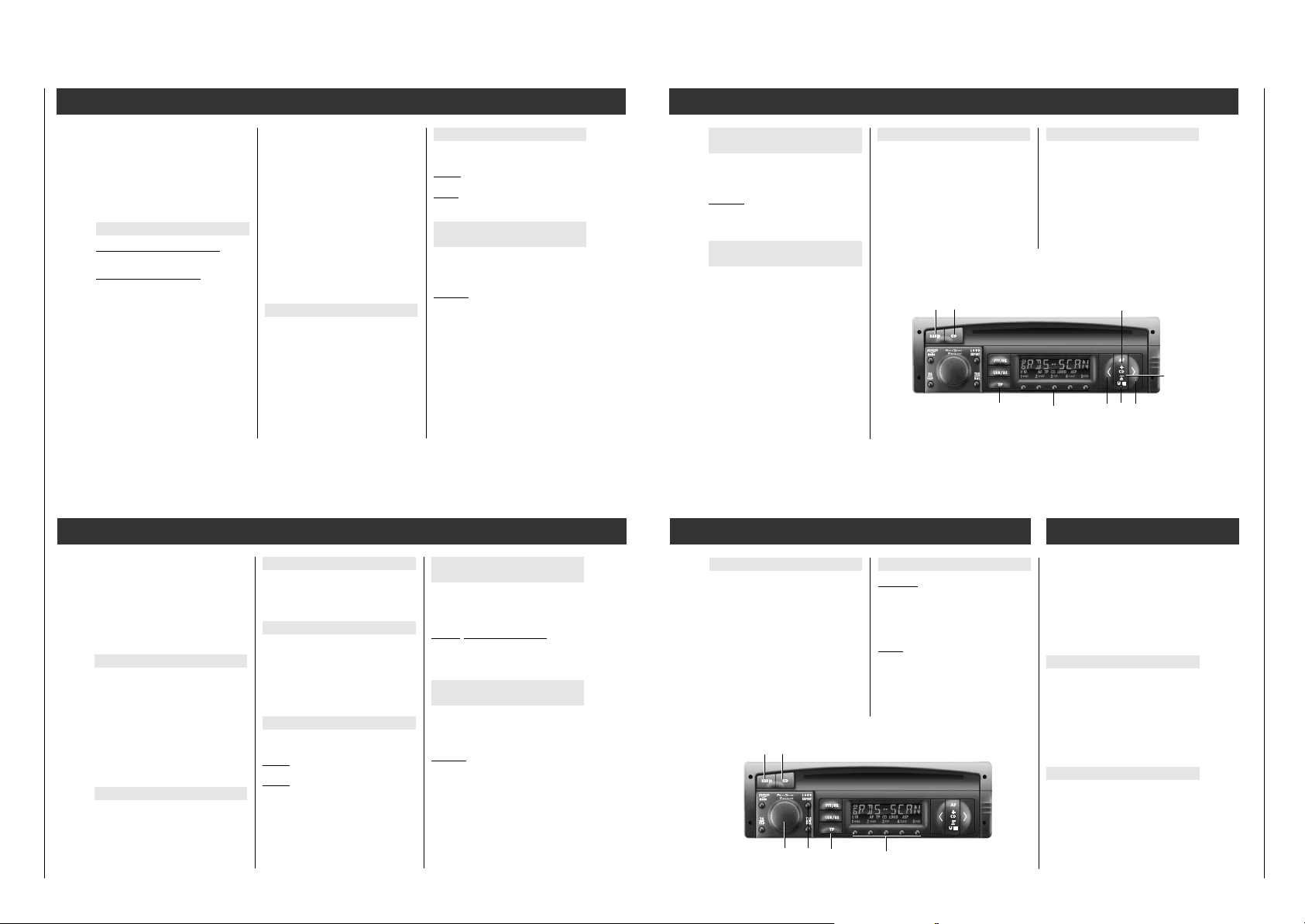
SCD 5690 RDS
1
4
2 3
5
a
b
c
C
B
A
1 4
3 6
2 5
1 3 5 7
2 4 6 8
1
2 4 6 8
10
12119
5 7
13 16 19
15 18
17 20
T 10 A
d
Page 10
Allgemeiner Teil / General Section SCD 5390 RDS / SCD 5690 RDS
1 - 10 GRUNDIG Service
ASP (Audio Sound Processing)
Using the Audio Sound Processing system,
you have the choice between various space
sound effects.
The first four station buttons are allocated to
the sound effects ”MOVIE”, ”DISCO”, ”VOI-
CE”, and ”MUSIC”.
Pressing the station button
5
exits the ASP
function.
The display indicates ”ASP OFF”.
Briefly press the
“
ASP
MONO .button.
Use the station buttons
1 to 4to select the
desired sound effect.
The display indicates, for example, ”MUSIC”.
íIn the case of mono broadcasts, or when
selecting mono manually, you will perceive a sound effect only when selecting
”VOICE”.
When you are in a zone of poor reception,
using the ASP function may increase reception distortions. If this should be the case,
switch off the ASP function.
Amplifier
Switching on and off on the car radio
Briefly press the ¢¢rotary knob.
Volume
Turn the ¢¢rotary knob.
The display indicates:
"VOL 00" … "VOL 46"
LOUD (loudness)
This function improves the sound quality at
low volume levels.
Loudness on/off
Briefly press the
“
LOUD
EXPERT
button.
With "Loudness" on, the display indicates
"LOUD".
“
BA
FAD
“
TRE
BAL
1– 5
“
ASP
MONO
¢¢
“
LOUD
EXPERT
Tone memory
It is possible to store various sound and
fader/balance settings by means of the station
buttons
1– 2
.
Storing settings
Set the bass, treble, fader, balance, and
loudness as desired.
When you are in one of the various setting
modes, press, for example, the station
button
1
until the signal sounds.
The display indicates "SOUND 1".
The set values are stored in memory.
Calling up settings
Press the
“
BA
FAD or
“
TRE
BAL button and then,
for example, briefly press the station button
1
.
Pressing the
“
BA
FAD or
“
TRE
BAL button and then
the station button
1
,calls up the linear (median) settings.
The display indicates "LINEAR".
BASS
Briefly press the
“
BA
FAD button.
Turn the
¢¢
rotary knob:
The display indicates:
"BASS -8"…"BASS 00"… "BASS + 8"
Terminate the setting:
Briefly press the
“
B
A
FAD button two times, or
automatically after approx. 10 seconds.
Immediate median position:
Press the
“
BA
FAD button until the signal
sounds.
FAD (Fader)
Front ɫ rear loudspeaker
Briefly press the
“
B
A
FAD button two times.
Turn the
¢¢
rotary knob:
The display indicates:
"FAD R31" … "FAD R - - F" … "FAD R31"
Rear Median position Front
Terminate the setting:
Briefly press the
“
BA
FAD button, or automati-
cally after approx. 10 seconds.
Immediate median position:
Press the
“
BA
FAD button until the signal
sounds.
Amplifier
TRE (Treble)
Briefly press the
“
TRE
BAL button.
Turn the
¢¢
rotary knob.
The display indicates:
"TREB - 14"…"TREB 00"… "TREB + 14"
Terminate the setting:
Briefly press the
“
TRE
BAL button two times,
or automatically after approx. 10 seconds.
Immediate median setting:
Press the
“
TR
E
BAL button until the signal
sounds.
BAL (Balance)
Left ɫright loudspeaker.
Briefly press the
“
TRE
BAL button two times.
Turn the
¢¢
rotary knob.
The display indicates:
"BAL L31"…" BAL L - - R"…"BAL R31"
Left Median position Right
Terminate the setting:
Briefly press the
“
TRE
BAL button, or automati-
cally after approx. 10 seconds.
Immediate median position:
Press the
“
TRE
BAL button until the signal
sounds.
Setting RDS programmes with the
LEARN memory
With the push of a button
you can store up to 24 RDS programmes in
the LEARN memory!
You can call up the stored RDS programmes
manually (RDS-SCAN) or automatically
(AUTOSCAN) one after the other.
Allocating the LEARN memory
Ranges: U I, U II or U III.
Briefly press the
¡
LRN/AS
button:
RDS programmes (max. 24) being received in
the reception area are stored in memory.
"LRN ..." appears in the display .
After storing you will hear the RDS programme having the best reception quality or only
RDS programmes with traffic announcements
if the
“
TP
button has been "activated".
On/off: press the
“
TP
button.
– manually
(RDS–SCAN)
(Repeatedly) briefly press the
“
< or “> but-
ton: "RDS SCAN" appears in the display.
After that you hear the next RDS programme.
Radio
– automatically
(AUTOSCAN)
Press the
¡
RADIO
button until the signal
sounds.
"AUTOSCAN" appears in the display.
After that all RDS programmes are called up
one after the other for approx. 10 seconds.
If the called up station is to be maintained,
briefly press the
¡
RADIO
button.
"RESET" appears briefly in the display.
Automatic station store
Autostore
The 5 strongest stations of the selected
range received in your reception are are
automatically stored in the station
buttons
1 – 4
Select the desired range: U I, U II, U III, MW
or LW.
Press the
¡
LRN/AS
button until the signal
sounds.
The display indicates "AS" and the frequency
scrolls on the display.
After that you hear the programme having the
best reception quality.
Programme types (PTY)
Prerequisite
The radio station tuned to must offer the "Programme types" service PTY in the VHF range.
Programme types
The programme types a radio station offers
change according to the programme being
broadcast.
NEWS News and current events
AFFAIRS Politics and current affairs
INFO Special talk programme
SPORT Sport programme
EDUCATE Learning and continuing
education
DRAMA Radio plays and literature
CULTURE Culture, church and society
SCIENCE Science
VARIED Talk entertainment
POP Pop music (hits)
ROCK M Rock music
M.O.R.M Light music
LIGHT M Light classical music
CLASSICS Serious classical music
OTHER M Music programmes that cannot
be categorised (e.g., Folklore)
NO PTY No programme type identifier
PTY programme buttons
The station button
are assigned to the following programme
types:
1
NEWS,2SPORT, 3POP (with
M.O.R.M) und
4
CLASSICS (with LIGHT M).
The station button
5
PERS (personal) can be assigned to a
programme type of your choice.
1. Switch on the PTY function.
Briefly press the
¡
PTY/DX
button.
2. Repeatedly press the
“
< or “> button
until the desired programme type is shown
in the display.
3. Press the
5
button until the signal sounds.
PTY function
1. Activating the PTY function
Press the
¡
PTY/DX
button briefly:
the last selected programme type is shown
in the display.
2. Set the desired programme type …
– with the PTY pro
gramme buttons
NEWS, SPORT, POP, CLASSICS or PERS
Press the respective button briefly:
the PTY search starts automatically and
moves to the next station offering the programme type selected. The display shows
"PTY ..."
– or –
Briefly press the
“
< or “> button until the
desired programme type is shown in the
display.
Press the
“
< or “> button until the signal
sounds.
The PTY search moves to the next station
offering the selected programme type and
the programme type, for example, "POP" is
shown.
If no station is offering the selected programme type, you will hear the station
last tuned to and the PTY function is
deactivated.
3. Deactivating the PTY function
Briefly press the
¡
PTY/DX
button, or
automatically after approx. 10 seconds.
Radio
¡
PTY/DX
1– 5
“
<“>
¡
CD
Page 11
SCD 5390 RDS / SCD 5690 RDS Allgemeiner Teil / General Section
GRUNDIG Service 1 - 11
í
On multimedia CDs, data tracks are recorded
in addition to the sound tracks. If you play
such a CD despite of the warning message,
noise may be generated in a volume which
can endanger traffic. In addition, the receiver’s
output stages and the loudspeakers may be
damaged.
Selecting the CD programme source
Insert a CD into the CD compartment.
The display indicates ”T01 00:00” – or –
a CD is in the CD compartment:
Repeatedly press the
¡
CD
button until the
display indicates ”CD”.
If the CD is not completely pulled in, the dis-
play will indicate ”NO CD”.
You can exit this condition by inserting the CD
once again or by pressing the
¡
CD
button.
Using the
¡
CD
button, you can switch between the built-in CD player and a connected
CD changer.
If you select the built-in CD player, the display
will indicate , for example, "T01 00:00".
If you select the CD changer, the display will
indicate "MCD 1" and then, for example,
"1 CD1 T01", or immediately "1 CD1 T01".
í
Attention with automatic aerials!
The radio switches automatically on as soon
as you insert a CD.
This causes also the aerial to be extended!
See also the note on page 3!
Selecting or repeating a track
Briefly (repeatedly) press the button until the
number of the desired track is shown in the
display.
“
> button: go to next track.
“
< button: go to previous track or repeat cur-
rent track.
Fast forward and reverse
To listen to tracks in "Quick preview" at
reduced volume:
Forward
Press and hold down the
“
> button.
Rewind
: Press and hold down the
“
< button.
Playing the tracks on a CD for approx.
10 seconds (TRACK SCAN)
Press the
¡
CD
button until the
signal sounds:
"TR SCAN" appears briefly in the display.
Terminate:
Briefly press the
¡
CD
button:
"RESET" appears briefly in the display.
CD Mode
Playing the tracks on a CD in random
order (TRACK RANDOM)
Press the
¡
U III
button until the
signal sounds:
"TR RND" appears briefly in the display.
Terminate:
Briefly press the
¡
U III
button:
"RESET" appears briefly in the display.
Enabling traffic announcements
during CD play
Activating TP
Briefly press the
“
TP
button.
"TP" appears in the display.
De-activating TP
Briefly press the
“
TP
button.
"TP" disappears from the display.
Terminating the CD mode
Select another programme source by briefly
pressing the
¡
CD
or
¡
RADIO
button or eject
the CD,
or
briefly press one of the station buttons
12345
.
Ejecting a CD
Briefly press the
¡
U III
button to eject the CD.
If the ejected CD is not removed within 15
seconds, it will be pulled in again for reasons
of safety.
If the CD is to be ejected after that, it is necessary to first press the
¡
CD
button and then
the
¡
U III
- button.
CD Mode
“
TP
1– 5
“
<
¡
U III
“
>
¡
RADIO¡CD
¡
CD
+
¡
CD
–
í
On multimedia CDs, data tracks are recorded
in addition to the sound tracks. If you play
such a CD despite of the warning message,
noise may be generated in a volume which
can endanger traffic. In addition, the receiver’s
output stages and the loudspeakers may be
damaged.
Selecting the CD programme source
Press the
¡
CD
button.
The display indicates, for example:
" MCD 1 ": if the internal CD player has
been selected before.
"CD 1 TO1": 1st CD - 1st track
"TO1 O1:15": 1st track - playing time of 1st
track.
"TR RND": "Tracks on CD in random
order.
Switching the display
Press the
¡
CD
+
button until the signal
sounds. For example:
"CD 1 TO1": 1st CD - 1st track, or
"TO1 O1:15": 1st track - playing time of 1st
track.
Selecting a CD
Briefly (repeatedly) press the
¡
CD
+
button or
¡
CD
–
button until the number of the desired
CD appears in the display.
Selecting or repeating a track
Briefly (repeatedly) press the button until the
number of the desired track is shown in the
display.
“
> button: go to next track.
< button: go to previous track or repeat cur-
rent track.
Fast forward and reverse
To listen to tracks in "Quick preview" at
reduced volume:
Forward
Press and hold down the
“
> button.
Reverse
: Press and hold down the
“
< button.
Playing the 1st track on every CD
for approx. 10 seconds (CD SCAN)
Press the
¡
CD
button until the signal
sounds:
"CD SCAN" appears briefly in the display.
If the pla
yed track is to be retained:
Briefly press the
¡
CD
button:
"RESET" appears briefly in the display.
Playing the tracks on a CD in random
order (TRACK RANDOM)
Press the
¡
CD
–
button until the
signal sounds:
"TR RND" appears briefly in the display.
Terminate:
Press the
¡
CD
–
button until the
signal sounds:
"RESET" appears briefly in the display.
*Your specialised dealer can inform you
which Grundig CD changer is suitable.
Compact Disc (CD) with "GRUNDIG CD Changer"*
Traffic announcements
Activating TP
Briefly press the
“
TP
button.
"TP" appears in the display.
Deactivating TP
Briefly press the
“
TP
button.
"TP" disappears from the display.
Ending CD mode
Radio mode
Press the
¡
RADIO
button,
or
briefly press one of the station
buttons
12345
.
CD play
Press the
¡
CD
button or insert a cassette
into the CD compartment.
í
On multimedia CDs, data tracks are recorded
in addition to the sound tracks. If you play
such a CD despite of the warning message,
noise may be generated in a volume which
can endanger traffic. In addition, the receiver’s
output stages and the loudspeakers may be
damaged.
Connecting a CD or DAT player
CD = Compact Disc (without CD changer)
DAT = Digital Audio Tape
If you have not connected a GRUNDIG CD
changer, you can also connect other CD
players of DAT players via a suited connecting
cable to the car radio (connect contact C 13 to
earth).
Activating CD or DAT mode
Selecting the CD programme source:
Press the
¡
CD
button. "AUX" appears in the
display.
CD or DAT Mode
Compact Disc (CD) with "GRUNDIG CD Changer"
¢¢
“
LOUD
EXPERT
“
TP
1– 2
¡
RADIO¡CD
Page 12

Allgemeiner Teil / General Section SCD 5390 RDS / SCD 5690 RDS
1 - 12 GRUNDIG Service
EXPERT
A great number of possible settings
To make car radio operation as easy as possible, numerous settings that you need only
once or occasionally are located in an additional control level (EXPERT).
Setting
1. Activating the EXPERT function
Press the
“
LOUD
EXPERT
button until the signal
sounds.
2. Selecting settings
Select from
the setting you wish to check or alter.
Example:
Turn the
¢¢
rotary knob until the desired
setting "LCD 25" appears in the display.
1 Change display contrast
Possible settings
1…ßZ
3. Activating the setting
Briefly press the
“
LOUD
EXPERT
button:
"
E" appears in the display
4. Changing the setting
Set the desired contrast using the
¢¢
rotary
knob. The display indicates, for example:
5. Ending the setting
Briefly press the
“
LOUD
EXPERT
button:
"
E" disappears from the display.
6. Selecting the next setting
(repeat the steps 2 to 5).
7. Deactivating EXPERT
Press the
“
LOUD
EXPERT
button until the signal
sounds.
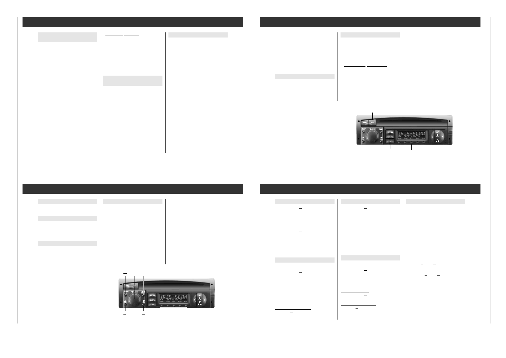
RDS
–
–
–
TP AF LOUD MONO ɳ ij CR
DX
E
LCD88853
RDS
–
–
–
TP AF LOUD MONO ɳ ij CR
DX
E
LCD88825
Possible settings 1…ßZ
Indication in the display: "......"
1 Contrast of the LCD display
"LCD 25" (00 … 63). Set according to the
location of the car radio so that the
display can optimally be read off.
2 Display colour
Vario-Color (green to red)
"COL 25" (00 … 53).
3 Security indication (on/off)
"BLK ON" The CD button is flashing when the
radio, the illumination, and the
ignition are switched off.
"BLK OFF" The CD button does not flash.
4 Sound signal (on/off)
"BEEP ON" Sound signal when changing a
function.
"BEEP OFF" No sound signal when changing
a function.
EXPERT Settings
LCD 25
5 Autom. LEARN (radio mode)
If you are in a reception area in which
reception of RDS programmes with traffic
announcements is poor, you can disable
the "Autom. LEARN (LRN) in radio mode"
function.
"LRN ON": autom. LEARN
"LRN OFF": no autom. LEARN for volume set-
tings greater than "VOL 4".
6 Autom. change of regional programme
If an RDS programme consists of various
regional programmes, it may occur that
your car radio changes between regional
stations when changing the reception area.
"REG ON" autom. change of regional
programme is possible.
"REG OFF" no change of regional
programme is possible.
7 Switching on and off with the
ignition/start switch
"IGN ON" It is possible to switch the radio on
and off with the ignition/start
switch of the vehicle.
"IGN OFF" Switching on and off is only possi-
ble with the
¢¢
rotary knob.
8 Muting in phone mode with car telephone
"PHONE OFF" No evaluation of the telephone
connection.
" PHONE ON" During a telephone call, the car
radio is automatically muted.
" PHONE IN" During a telephone call, the car
radio is automatically switched
on and the telephone conversation is heard via the loudspeakers.
If you change the tone and balance settings
during a telephone call, these alterations
remain stored for the next telephone call.
When switching back to radio mode, the set
recovers the original tone and balance settings.
í PLease also read the notes in
the chapter "Attention with automatic
aerials" on page 3.
9 CD input sensitivity
Adapting a CD changer:
"MCD LOW" low
"MCD MID" median (e.g. MCD 30)
"MCD HIGH" high
ßI Volume limitation when switching on
"ONVOL - -": no limitation or
"ONVOL 35": max. volume, e.g. 20
(- - … 11 ...35).
The volume is limited only if the volume
when the car radio is switched off is
greater than the set value!
9 Minimum volume for traffic
announcements
"TA VOL 16" (5 … 35)
í For reasons of traffic safety, the volu-
me for traffic announcements should be
set to a moderate level!
EXPERT
ß` Speed-controlled volume
"SCVOL 124" (- - … 144)
Setting is only possible if a speed-controlled signal is present on the SCV connection
(A1).
" SCVOL - - " : SCV switched off.
" SCVOL 144 " : maximum effect.
Setting
1. Car standing still, motor running:
set desired volume with
¢¢
rotary knob.
2. Prepare EXPERT setting:
press the
“
LOUD
EXPERT
button until signal
sounds.
Turn
¢¢
rotary knob until e.g.
" SCVOL ..." appears in the display.
Briefly press the
“
LOUD
EXPERT
button:
»
E « appears in the display.
3. At higher speed:
use the
¢¢
rotary knob to set the required
volume, e.g." SCVOL 124 " in display.
Press the
“
LOUD
EXPERT
button until the signal
sounds.
í
For reasons of safety the following
setting should be carried out by the
passenger!
Acoustic system
It is possible to separately adjust the bass and
treble for the rear and front loudspeakers.
The setting can be changed in the range of –3
to +3 with the
¢¢
knob.
ßQ Bass – front loudspeakers
”BAS F 0” (F = Front)
ßW Bass – rear loudspeakers
”BAS R 0” (R = Rear)
ßE Treble – front loudspeakers
”TRE F 0” (F = Front)
ßR Treble – rear loudspeakers
”TRE R 0” (R = Rear/hinten)
ßT On/Off switching delay for connected
booster
(booster switching voltage = contact C6)
" BDLY ... " (O6 … 99)
If “switching noise” occurs: increase set
value until switching noise is no longer
audible.
ßZ Activating the coding
If "CODE" appears in the diplay, coding is
not activated.
If "SAFE" appears in the display, coding is
activated.
Your car radio has been designed throughout
to ensure maintenance-free operation over an
extended period of time.
If a malfunction
should occur, please consult your dealer.
In the Federal Republic of Germany, Grundig
car radios can be exchanged by your dealer
on request for a works-tested exchange unit
in the event of a defect occuring.
Please note:
It is a condition for your dealer to participate
in this exchange system that the guarantee
seal on your car radio is not damaged.
Cassettes must not be subjected to high
temperatures (see manufacturer's specifications) and should be put into their case after
use.
The front panel of the car radio must only be
cleaned with a soft, dust-absorbent, anti-static
cloth. Polishing and cleansing agents may
damage the surface of the trimplate.
The tape head must be free of tape dust in
order to avoid losses in the treble tones
during playback. Therefore you should clean
the tape head with a cleaning cassette after
every 50–100 hours of operation.
Maintenance and Care
EXPERT
Coding
Your personal code number is on the identity
card of your car radio.
Coding is not activated when the radio leaves
the factory.
If you have “activated” your car radio's
coding:
As soon as you disconnect the car radio from
the car battery (or permanent plus terminal
30), it is electronically blocked.
Only you are able to put it back into operation
by entering your personal Code Number.
If the Code Number is lost (Identity Card),
only a dealer can put the radio back into
operation after you provide proof of ownership and pay a fee.
Is the coding activated?
Activate the expert mode and turn the
¢¢
rotary knob until the display indicates
"SAFE" or "CODE".
"SAFE" Coding activated.
"CODE" Coding not activated.
Activating coding
1. The expert mode is switched on and
"CODE" appears in the display.
Activate the setting:
Briefly press the
“
LOUD
EXPERT
button.
The display indicates "
E
- - - -"
2. Enter the code number (on the Identity
Card):
Repeatedly press the buttons
1– 4
until
the code number is shown in the display.
Example: 1703 Display:
Button
1
11 brief pressure >1 - - -<
Button
2
17 brief pressures >1 7 - -<
Button
3
10 brief pressures >1 7 0 -<
Button
4
13 brief pressures >1 7 0 3<
When pressing a longer time, the corresponding figure counts backwards.
3. Confirm the code number:
Briefly press the
“
LOUD
EXPERT
button. The
display indicates "SAFE".
Codin
g is activated!
Waiting periods
To prevent deactivation of the coding being
possible by trial and error
, waiting periods are
required between attempts. During these waiting periods the car radio can be switched on
and off but will not play.
Durin
g the waiting period
the car radio needs not be switched on, but it
must be connected to the permanent plus terminal. As long as the display indicates "SAFE",
the waiting period has not yet elapsed.
The waiting period is over when the number
of the next attempt is visible in the display,
e.g. "2 - - - -".
The table shows
the waiting
periods between
the individual
attempts.
Waiting period
after the 7th
attempt is
always 24hrs!
After the 6th
attempt we
recommend having a dealer complete the
“Return to operation” or “Deactivate coding”
process.
Attempt Wait.per.
(in display) (approx.)
1
21 sec.
2
1.5 min.
3
5.5 min.
4
22 min.
5
1.5 hrs.
6
6.0 hrs.
7
24 hrs.
8
24 hrs.
Coding
Page 13

SCD 5390 RDS / SCD 5690 RDS Allgemeiner Teil / General Section
GRUNDIG Service 1 - 13
Installation and removal
Installation materials and accessories
Your dealer can advise you as to what installation materials you will need and what accessories are available.
Inserting the mounting frame
Figure o
– Insert mounting frame b into cutout a of the
vehicle.
– Bend the tabs c behind cutout a as required
(depending on type of vehicle).
With cars of the VW/Audi company, from
1991 models on: make sure not to connect
the contact blade A7 with the S contact
(supply plug PIN 4 – brown/red cable) of
the car.
The figures o – a can be found at the
beginning of this booklet.
Return to operation
The car radio is electronically disabled after it
has been disconnected from the car battery
(or permanent plus, terminal 30), e.g. after
the radio has been removed during servicing.
1. Switch the car radio on:
The display indicates "SAFE".
After approx. seconds, it will indicate
"I - - - -".
2. Enter the code number (on Identity Card),
as described in the chapter "Activating
coding".
3. Confirm the code number:
Briefly press the
“
LOUD
EXPERT
button. The display
indicates briefly "SAFE".
After approx. 3 seconds the radio will play.
Entr
y of incorrect code number:
"SAFE" remains in the display and the radio
does not play.
Begin again.
Be sure to observe the waiting periods
between
attempts.
Deactivating coding
e.g., before removing the car radio:
1. The expert mode must be switched on and
"SAFE" visible in the display.
Activate the setting.
Briefly press the
“
LOUD
EXPERT
button.
The display indicates "
E 1 - - - -"
2. Enter the code number (on Identity Card),
as described in the chapter "Activating
coding".
3. Confirm the code number:
Briefly press the
“
LOUD
EXPERT
button. The display
indicates briefly "CODE".
After approx. 3 seconds the radio will play.
Coding is deactivated!
Entr
y of incorrect code number:
"SAFE" remains in the display and the radio
does not play.
Begin again.
Be sure to observe the waiting periods
between
attempts.
Coding Installation and Removal
Supply voltages
Blade contacts A: Figure +
A8 – operating voltage (earth)
Connect to terminal 31
(earth) of the vehicle.
A7 +12 V operating voltage
Connect to terminal 30
(permanent plus) of
the vehicle.
A6 Car radio illumination
Connect the blade contact A6 to terminal 58
of the vehicle.
When the vehicle's headlights are switched
on, the illumination of of the car radio can be
controlled.
Blade contact A6 not connected:
The car radio illumination cannot be changed.
A5 +12 V switching voltage output
(max. 0.5 A)
on bladec contact A 5 when the radio is
switched on.
For automatic aerial (extend/retract),
aerial amplifier (operating voltage) etc.
A4 +12 V ignition voltage
Connect to terminal 15
or terminal 30 of the
vehicle.
– Terminal 15
, if you wish to switch the car
radio on and off with the ignition/start
switch.
– Terminal 30
, if you do not wish to switch
the car radio on and off with the
ignition/start switch.
A2 Phone connection (Mute)
for car telephone or CB radio.
The car radio is “muted” when the car telephone or CB radio is in operation.
For this, the blade contact A2 must be
connected from the mute output of the telephone/CB radio to earth!
í
Attention with automatic aerials!
The radio switches on automatically if
a connected telephone/CB radio receives
a call.
A1 SCV connection (+)
for "speed-controlled Volume".
Loudspeakers
Blade contacts B: Figure +
Maximum output power
with 4Ω loudspeakers:
Peak power ___________________ 4 x 50 W
Sine power, DIN 45324 __________ 4 x 25 W
Front speakers Rear speakers
B3 right-hand +B1right-hand +
B4 right-hand –B2right-hand –
B5 left-hand +B7left-hand +
B6 left-hand –B8left-hand –
í
Do not electrically connect speaker
connections to each other and do not
connect to chassis!
Aerial
The car radio is designed for aerials with an
impedance of 75Ω to 150Ω. Extended aerial
cables, e.g. for aerials at the rear of the car,
may impair reception.
Figures
p and ü
– If necessary, use the aerial adapter (fig. p).
– Fix the aerial adapter (fig.
p) or aerial cable
(fig.
ü) in the plastic holder.
Additional connections
Blade contacts C: Figure +
CD connection
C13 CD bus
C15 Supply voltage, earth.
C16 +12 V supply voltage.
C17 Switching voltage.
C18 CD AF, earth.
C19 CD AF, left.
C20 CD AF, right.
Line output
Connection for booster or active speaker.
C11 Rear speaker, left +
C12 Rear speaker, right +
C13 Earth –
C14 Front loudspeaker, left +
C15 Front loudspeaker, right +
C16 Switching voltage for booster on/off
(max. 0.3 A).
Subwoofer output
It is possible to connect a Subwoofer power
amplifier to the Subwoofer frequency separting filter integrated in the set.
C19 Subwoofer – Earth
C10 Subwoofer – AF
Phone input
For the conection of a car telephone or CB
radio (monitoring via the car radio).
C11 Phone AF
C12 Phone AF, earth
Inserting the car radio
Figure o
– Insert the car radio all the way into the
installed mounting frame b.
The car radio should snap into place.
Removing the car radio
Figure a
– Remove the control panel (page 4).
Insert both removal handles d as far as possible into the openings in the trim.
– Press both removal handles outward
ɫ
and slowly pull the radio out.
Fuse T 10 A
Figure +
Blade-type fuse T 10A /DIN 72 581– plugged.
Installation and Removal
SCD 5690 RDS
1
4
2 3
5
b
C
B
A
1 4
3 6
2 5
1 3 5 7
2 4 6 8
1
2 4 6 8
10
12119
5 7
a
c
13 16 19
15 18
17 20
T 10 A
d
Page 14

Abgleichvorschriften / Adjustment Procedures SCD 5390 RDS / SCD 5690 RDS
D
Abgleichvorschriften
Meßgeräte:
DC-Voltmeter, NF-Voltmeter, Meßsender, Stereocoder, Wobbler
Abgleich Vorbereitung Abgleichvorgang
1. MW-Oszillator
2. LW-Oszillator
3. MW-Vorkreis
4. LW-Vorkreis
5. AM-ZF
6. FM-Oszillator
7. FM-Demodulator
8. FM-Zwischenkreis
9. FM-Vorkreis
MW;
DC-Voltmeter an FMP604.
LW;
DC-Voltmeter an FMP604.
Meßsender an Antenneneingang; MW; m = 0,3; f
E´ ≤ 10µV (20dBµV).
= 1kHz;
mod
NF-Voltmeter an Lautsprecher-Ausgang.
Meßsender an Antenneneingang; LW; m = 0,3; f
E´ ≤ 10µV (20dBµV).
= 1kHz;
mod
NF-Voltmeter an Lautsprecher-Ausgang.
Meßsender an Antenneneingang; MW; Frequenz 990kHz;
m = 0,3; f
NF-Voltmeter an Lautsprecher-Ausgang.
= 1kHz; E´ ≤ 10µV (20dBµV).
mod
FM; DC-Voltmeter an FMP04.
Meßsender an Antenneneingang; Frequenz 93,0MHz;
f
= 1kHz; Hub = 22,5kHz; E´ = 100µV (40dBµV).
mod
NF-Voltmeter an Lautsprecher-Ausgang.
Meßsender an Antenneneingang; Frequenz 93,0MHz;
f
= 1kHz; Hub = 22,5kHz; E´ = 3µV (10dBµV).
mod
NF-Voltmeter an Lautsprecher-Ausgang.
Meßsender an Antenneneingang; Frequenz 93,0MHz;
f
= 1kHz; Hub = 22,5kHz; E´ = 3µV (10dBµV).
mod
NF-Voltmeter an Lautsprecher-Ausgang.
Mit L 612 (1) bei 531kHz auf 1,2V ± 50mV abgleichen.
Kontrolle bei 1602kHz auf 7,5V ± 0,5V.
Mit L 613 (5) bei 153kHz auf 1,3V ± 50mV abgleichen.
Kontrolle bei 279kHz auf 5,0V ± 0,5V.
Wechselweise mit L 603 (3) bei 558kHz und mit C 606 (4)
bei 1548kHz auf NF-Maximum abgleichen.
Wechselweise mit L 604 (7) bei 162kHz und mit C 607 (8)
bei 261kHz auf NF-Maximum abgleichen.
Mit F 601 (9) auf NF-Maximum abgleichen.
Mit L 04 (A) bei 93,0MHz auf 2,6V ± 20mV abgleichen.
Mit F 105 (I) auf NF-Maximum abgleichen.
Mit L 03 (C) auf NF-Maximum abgleichen.
Mit L 01 (D) auf NF-Maximum abgleichen.
10. FM-ZF
11. FM-Stoppgenerator
12. Feldstärkepegel
14. Dolby
Meßsender an Antenneneingang; Frequenz 93,0MHz;
f
= 1kHz; Hub = 60kHz; E´ = 3µV (10dBµV).
mod
NF-Voltmeter an Lautsprecher-Ausgang.
Wobbler an Antenneneingang; Mittenfrequenz 93,0MHz;
∆f = 100kHz; E´ = 1mV (60dBµV); ohne Modulation.
Oszilloskop an FMP107.
Meßsender an Antenneneingang; Frequenz 93,0MHz;
E´ = 100µV (40dBµV); ohne Modulation.
DC-Voltmeter zwischen FMP102 (+) und FMP106 (-).
Test-Cassette 448A einlegen und Dolby Pegelteil 315Hz
abspielen.
NF-Voltmeter an FMP1107 (linker Kanal) bzw. FMP1108
(rechter Kanal) anschließen.
Mit F 101 (F) auf NF-Maximum abgleichen.
Mit F 105 (I) auf symmetrischen Stoppimpuls abgleichen.
93,0MHz
+5V
0V
∆f = ± 28kHz
Mit R 105 (H) auf +400mV ± 20mV einstellen.
Mit R 1110Z (L) für den linken Kanal bzw. mit R 1113Z (M)
für den rechten Kanal auf 490mV einstellen.
2 - 1 GRUNDIG Service
Page 15

SCD 5390 RDS / SCD 5690 RDS Abgleichvorschriften / Adjustment Procedures
GB
Adjustment Procedures
Test equipment:
DC Voltmeter, AF Voltmeter, Test Generator, Stereo Coder, Sweep Generator
Adjustment Preparation Adjustment Procedure
1. MW Oscillator
2. LW Oscillator
3. MW Band Pass
4. LW Band Pass
5. AM IF
6. FM Oscillator
7. FM Demodulator
8. FM Band Pass
9. FM Aerial Band
Pass
MW;
Connect a DC Voltmeter to FMP604.
LW; Frequency 153kHz.
Connect a DC Voltmeter to FMP604.
Connect a Test Generator to aerial input; MW; m = 0.3;
f
= 1kHz; E´ ≤ 10µV (20dBµV).
mod
Connect AF Voltmeter to Loudspeaker Output.
Connect a Test Generator to aerial input; LW; m = 0.3;
f
= 1kHz; E´ ≤ 10µV (20dBµV).
mod
Connect AF Voltmeter to Loudspeaker Output.
Connect a Test Generator to aerial input; MW; Frequency
990kHz; m = 0,3; f
Connect AF Voltmeter to Loudspeaker Output.
= 1kHz; E´ ≤ 10µV (20dBµV).
mod
FM; Connect a DC Voltmeter to FMP04.
Connect a Test Generator to aerial input; Frequency
93.0MHz; f
Connect AF Voltmeter to Loudspeaker Output.
= 1kHz; dev. 22.5kHz; E´ ≤ 100µV (40dBµV).
mod
Connect a Test Generator to aerial input; Frequency
93.0MHz; f
Connect AF Voltmeter to Loudspeaker Output.
= 1kHz; dev. 22.5kHz; E´ ≤ 3µV (10dBµV).
mod
Connect a Test Generator to aerial input; Frequency
93.0MHz; f
Connect AF Voltmeter to Loudspeaker Output.
= 1kHz; dev. 22.5kHz; E´ ≤ 3µV (10dBµV).
mod
Align with L 612 (1) at 531kHz to 1.2V ± 50mV.
Check at 1602kHz for 7.5V ± 0.5V.
Align with L 613 (5) at 153kHz to 1.3V ± 50mV.
Check at 279kHz for 5.0V ± 0.5V.
Align alternating with L 603 (3) at 558kHz and with C 606 (4)
at 1548kHz for maximum AF output.
Align alternating with L 604 (7) at 162kHz and with C 607 (8)
at 261kHz for maximum AF output.
Align with F 601 (9) for maximum AF output.
Align with L 04 (A) at 93.0MHz for 2.6V ± 20mV.
Align with F 105 (I) for AF maximum.
Align with L 03 (C) for AF maximum.
Align with L 01 (D) for AF maximum.
10. FM IF
11. FM Stop
Generator
12. Field Strength
Level
14. Dolby
Connect a Test Generator to aerial input; Frequency
93.0MHz; f
Connect AF Voltmeter to Loudspeaker Output.
= 1kHz; dev. 60kHz; E´ ≤ 3µV (10dBµV).
mod
Connect a Sweep Generator to aerial input; FM; Center
frequency 93.0MHz; ∆f = 100kHz; E´ = 1mV (60dBµV); no
modulation.
Connect an Oscilloscope to FMP107.
Connect a Test Generator to aerial input; Frequency
93.0MHz; E´ = 100µV (40dBµV); no modulation.
Connect DC Voltmeter between FMP102 (+) and
FMP106 (-).
Play Test Cassette 448A (315Hz Dolby part).
Connect AF Voltmeter to FMP1107 (left channel) resp.
FMP1108 (right channel).
Align with F 101 (F) for AF maximum.
Align F 105 (I) for a symmetrical stop impulse.
93,0MHz
+5V
0V
∆f = ± 28kHz
Align with R 105 (H) for +400mV ± 20mV.
Adjust R 1110Z (L) for the left channel resp. R 1113Z (M)
for the right channel for 490mV.
GRUNDIG Service 2 - 2
Page 16

Abgleichvorschriften / Adjustment Procedures SCD 5390 RDS / SCD 5690 RDS
Alignment LayoutAbgleichlageplan
C2008
IC1601
IC1602
R105
(H)
106
Q201
CIC101
(I)
F105
L612
L613
604
Q701
Q801
04
F104
(1)
(5)
F103
F102
(A)
107
(F)
F101
3
F602
L04
12
4
1108
(C)
L03
(9)
C607
C606
F601
(8)
(4)
CIC1101Z
L604
(7)
(3)
1107
BU8Z
L01
(D)
L603
R1113Z
(M)
(L)
R1110Z
1
5
IC1351C
IC2001
L2001
12
IC2002
17
15
2
1
15
2
1
BU05
16
BU06
101
AIM
BU7Q
1
2
ST1Y
7
8
1
2
7
102
AM
EMK
E´ = EMK / 2
Ri
50 Ω
E´
BU02
1
11
BU02
19373-350.00(05) 4B
Meßpunkt (FMP...)
Test Point (FMP...)
Abgleichpunkt
( )
Adjustment Point
Zum Abgleich die Antennennachbildungen für AM bzw. FM verwenden.
For adjustment use the aerial dummies for AM resp. FM.
37,5 Ω 55 Ω
15 p
Ue = E´ / 10
U
e
FM
E´ = EMK / 2
Ri
E´
10 Ω 45 Ω
Ue = E´ / 2
Ue
50 Ω
EMK
150 Ω
37,5 Ω
60 p
75 Ω
60 Ω
75 Ω
2 - 1 GRUNDIG Service
Page 17

SCD 5390 RDS / SCD 5690 RDS Schaltpläne und Druckplattenabbildungen / Circuit Diagrams and Layout of PCBs SCD 5390 RDS / SCD 5690 RDS Schaltpläne und Druckplattenabbildungen / Circuit Diagrams and Layout of PCBs
Schaltpläne und Druckplattenabbildungen / Circuit Diagrams and Layout of PCBs
Bauteilhinweise / Notes on Components
WIDERSTAND/RESISTOR
KSW 0204 DIN
MSW 0204 DIN
KSW 0207 DIN
MSW 0207 DIN
MSW 0414 DIN
KSW 0411 DIN
KSW 0617 DIN
MSW 0309 DIN
METALLOXYDSCHICHT
METAL OXYDE
RAUSCHARM
LOW NOISE
SCHWER ENTFLAMMBAR
LOW FLAMMABILITY
DRAHT
WIRE
NTC
PTC
KONDENSATOR/CAPACITOR
+
ELKO
ELECTROLYTIC
+
T
TANTAL ELKO
TANTALUM ELECTROLYTIC
F
FOLIE
FOIL
K
KERAMIK
CERAMIC
P
POLYPROPYLEN
(KS-KP)
BIPOLAR
KENNZEICHNUNG VON CHIP-BAUTEILEN
CODING OF CHIP-COMPONENTS
CC = CHIP-KONDENSATOR/-CAPACITOR
CR = CHIP-WIDERSTAND/-RESISTOR
CD = CHIP-DIODE/-DIODE
CT = CHIP-TRANSISTOR
CL = CHIP-SPULE/-COIL
CR:0R = CHIP-BRUECKE/-JUMPER
A
BB 804
BB 814
BB 824/2+3
KV 1410/2+3
K
CD CD CD
A2K1
BAV 99
K2 A1
CD CD
LSG A 671
CD CD
BC 808
BE
BC 818
BC 848
BC 849
BC 850
BC 858
C
BC 859
CT
BCR 142
BCR 192
BCP 54
BF 840
BF 841
DTA 144VK
DTC 114YK
DTC 115EK
DTC 143ZK
DTC 144EK
A
1SV128
BA 779S
BAS 16
BZX 84C...
Z 47
K
A1K2
1SV172
K1 A2
3
2
4
1
GD
BF 543
BF 543E
BF 999
S
CT
FMQ1
1
CT
K
( GRUEN )
( ROT )
LSG T671
G2G1
DS
CT
CT
A
BF 992A
MOS
IMH2
IMH10
IMB10
BB 512
BB 620
( Vorderansicht )
( front view )
1
XXXX
TDA 7375 AV
KERAMIKFILTER
CERAMIC-FILTERS
8602-810-055
SPULEN UND FILTER ( 7x7 / 5x5 )
COILS AND FILTERS ( 7x7 / 5x5 )
FARB - CODE
COLOUR CODE
3
12
888777
46
07202-346.97
07202-610.97
07202-613.97
07202-618.97
07202-619.10
07202-702.97
192028140-533-118
15
1412108642
15131197531
21
3
8140-533-121
8140-533-161
8140-533-163
8140-533-165
8140-535-095
8140-535-101
8140-535-103
8140-535-105
8140-535-115
8140-535-251
8140-535-255
8141-102-040
8141-114-184
8141-114-185
8141-114-476
8141-114-477
8141-118-350
UKW - SPULEN
VHF - COILS
TOKO-TYP MC 122
2
34
1
8140-530-250
8140-530-255
8140-530-269
8140-530-270
100ER10ER
100ER10ER
1ER1ER
BCE
BC 368
BC 369
1N4001
1N5401G
AK
SW = SCHWARZ
BLACK
GE = GELB
YELLOW
VI = VIOLETT
VIOLET
RS = ROSA
PINK
BN = BRAUN
BROWN
GN = GRUEN
GREEN
GR = GRAU
GREY
OR = ORANGE
RT = ROT
RED
BL = BLAU
BLUE
WS = WEISS
WHITE
NF = NATURFARBEN
NATURAL COLOUR
ACHTUNG!
VORSCHRIFTEN BEIM UMGANG MIT
MOS-BAUTEILEN BEACHTEN!
ATTENTION!
OBSERVE MOS COMPONENT HANDLING
INSTRUCTIONS WHEN SERVICING!
2333
34
44
111
TDA 7340G
TDA 7344P
XXX
8602-333-010
CSB 456 FB 11
( Vorderansicht )
( front view )
XXX
123
19203-020.97
19203-127.97
8602-222-190
616819
10
22
26
12
27 43
68HC11KA4
60
44
1
TDA 1072AT
TDA 1575T
TDA 1593T
L 4949ND
L 9820D
HEF 4001BT
SAA 6579T MOS
HEF 4077BT
U 4286BM
TEA 0675T
( Vorderansicht ) ( Vorderansicht )
( front view ) ( front view )
L 9821L 4892CV
AENDERUNGEN VORBEHALTEN
531231
SUBJECT TO ALTERATION
Alle Rechte vorbehalten
Weiterverwertung,insbesondere
Nachahmung oder sonstiger
Missbrauch des geistigen
Eigentums wird zivil- und
strafrechtlich verfolgt.
BAUTEILANSICHT
GENERELL VON OBEN, WENN NICHT
ANDERS VERMERKT
COMPONENT VIEW
ALL COMPONENTS FROM TOP,
IF NOT OTHERWISE
MESSPUNKTE
ABGLEICHPUNKTE
GRUNDIG Service 3 - 1 GRUNDIG Service 3 - 2
Page 18

Schaltpläne und Druckplattenabbildungen / Circuit Diagrams and Layout of PCBs SCD 5390 RDS / SCD 5690 RDS Schaltpläne und Druckplattenabbildungen / Circuit Diagrams and Layout of PCBs SCD 5390 RDS / SCD 5690 RDS
O
F
3
S
A
HF-Teil / RF Part
MISCHTEIL
BU01
FMP01
FMP02
C01
33P
400V
FMP03
AM-ANT
C
*
*
CT01
CC02
1N0
400V
DTA143EK
CD01
CT02
*
BA779
3P3
CR01
CC34
CD02
*
BB814
1302-001 4/76
47K
1N0
K
CD03
BA779
*
K
C03
4K7
4K7
CR16
1K0
CR17
1K0
L01
1234
8140-530-255
+
C27
22U/16V
BF999
D
D
GS
10R
CR03
8V9
CC07
*
1P8
CC08
8V5
CL02
*
CR08
CC36
10P
2UH2
8140-516-057
10R
47N
CC11
CR04
34
L03
1
1302-001 4/76
CD04
BB814
CC14
6P8
47K
CR02
100K
FMP04
1N0
47N
CC23
470R
CR13
2V7 BEI 93MHZ6
FM-ABST
MIXER SECTION
8140-530-255
2
CC16
6P8
BALANCED
15P
CC17
8V5 8V5 8V58V5
MIXER
200R
16 15 14 13 12 11 10 9
+
C24
2U2/50V
CD06
BB814
CC21
*
CC18
8P2
*
+
8305-841-575
50uA
+
F
234
8141-114-477
1
678
FMP06
CIC01
1,7V
CR104
*
*
CC32
10N
4V1 1V2 1V21V81V71V1
REFERENCE
VOLTAGE
TDA1575T
CR101
120R
270R
CC35
1V3
123
1P0
3P9
CC22
F101
10N
300R
F102
CC26
CC102
8P2
OSZ.
IF AMPLIFIER
10N
8602-222-190
1N0
CC31
*
CR21
*
470R
OSCILLATOR
BUFFER
950R
300R
87654321
CC28
6P8
7V64V21V3
8602-222-190
F103
123
FMP05
CR113
CR112
820R
470R
CC30
8602-222-190
F104
123
470R
CR114
CC29
3K9
CR15
10K
1N0
CR14
FM-OSZ
L04
8140-530-250
1234
A
4P7
FMP101
ZFVERSTAERKER
PEGELDETEKTOR
U
1 23456
+
C106
100N
CC101
10U/16V
CR106
+FM+FM
CR102
ST
8V7
10R
8V9
330R
FM-ZF-TEIL
FM-IF SECTION
22N
CC103
CC104
22N
1V81V81V8
UREF
R105
FELDSTAERKE
CR107
FELDST
TDA
1593T
8305-841-593
H
CR111
15K
15K
FMP102
4K7
CR103
10K
*
CT101
BC848C
CC114
10N
*
CIC101
CR108
*
*
C105
3V1
4K7
CC107
MPX2
CT102
BC848C
*
+
2V5
U47/50V
68P
FMP107FMP105
ABSTIMMSTOP-LOGIK
FMP106
MPX1
STUMMSCHALTUNG
FMP104
CR119
47K
CR118
10K
0V
FM-AU
3V9
UREF
114151617181920
CD601
*
CR600
BAV99
100K
AM-ANT
2UH2
CL601
*
8140-526-472
400V
K
1N0
C601
220K
CR601
CR604
*
100R
180K
CR602
**
FMP601
6V9
8140-533-161
8140-533-121
CR606
1M0
CC604
MW
L603
LW
L604
CT602
*
G1
G2 S
BF992A
47N
781
781
D
34
6
34
6
CR607
7V6
270R
CR625
C616
+AM
F601
CC620
GRI
CR631
9
8140-533-130
34
NP02N2
CR648
FMP605
CC631
100N
47K
CR627
12K
781
6
8V0
DOUBLE
BALANCED
MIXER
+
GAIN-
CONTROLLED
RF STAGE
16 15 14 13 12 11
CC632
220P
CT613
*
BC848C
22K
CR632
22R
+
47U/16V
8V0
CC628
*
22N
CD608
BB512GR2
100N
CC630
STANDBY
CR633
*
1
1K8
*
CIC601
SWITCH
3V6
22K
8602-810-055
F602
E
GND
2
2V2
CR626
GAIN CON-
TROLLED IF
AMPLIFIER DETECTOR
VR(AGC)
V1
22N
CC637
270P
CC634
5K6
3K
V1 V2 V3
INTERNAL
VOLTAGES
3
A1
A2
4
2V2
V2
VR(AGC)
SUPPLY
47N
CC638
8140-535-115
1378
8140-535-105
1378
AM-NF
FMP607
10K
47N
CC622
2V2 0V6 0V3 1V2
BALANCED
FULL-WAVE
CONTROLLED
OSCILLATOR
22R
CR636
L612
MW
CC641
1
CR629
*
CC623
7K
3K525R
VR
AF PRE-
AMPLIFIER
TDA1072AT
8305-841-072
V3
4V24V2 0V7
18P
22N
+
C625
AMPLIFIER
170R
10 9
*
L613
150P
LW
CC640
5
1U/50V
7K
AGC
CT617
BC848C
+
C626
87654321
INDIKATOR
DRIVER
220R
CR637
*
10U/16V
CR642
47K
CC642
100N
+MW
RDS-D
+LW
FMP611
AM-OSZ
RDS-CL
12
QUALITY-
GENERATOR
16 1415
RDCL T57 OSC
RDDAQUAL
DIFFERENTIAL
BIPHASE
DECODER
BIT
REGENERATION
C508
VRE
DECODER
SYMBOL
CLOCK
AND SYNC
FMP501
CC502
FELDST
FMP609
2K2
2K2
22N
CR644
CC644
1V2 BEI 531 KHZ
1V3 BEI 152 KHZ
CC621
*
1N0
CD603
5P5-30P
7P5-45P
CR608
2K7
CC609
BB512GR2
CR613
47K
100N
CT603
*
BC818/25
CR612
*
C606
3
4
C607
87
3V2
100N
CC608
82R
CR609
AM-ABST
22K
CT607
BC848C
CC617
+
C603
CC615
CR623
CR624
22R
47N
10U/16V
22N
8R2
CC613
1N0
120R
22N
*
CT608
10K
47K
7V6
3K3
CR617
CR619
680K
CC612
10N
**
CT604
BC848C
120R
CR618
*
82R
CR622
CC614
*
*
100K
CR614
*
8140-526-475
CL606
*
8UH2
CC624
*
470P
1N5
CR611
CR630
10K
CT606
*
D
G
S
BF543
CR647
*
1M0
CR621
*
1K5
CC627
*
DTC114YK
FMP604
MESSPUNKTE
ABGLEICHPUNKTE
601 604
0302 04
4
D
37
8
06
C
F
9
05
1
5
A
101
609607605
105
102
611
H
104
107
106
3 - 3 GRUNDIG Service 3 - 4 GRUNDIG Service
Page 19

SCD 5390 RDS / SCD 5690 RDS Schaltpläne und Druckplattenabbildungen / Circuit Diagrams and Layout of PCBs SCD 5390 RDS / SCD 5690 RDS Schaltpläne und Druckplattenabbildungen / Circuit Diagrams and Layout of PCBs
G
CR119
47K
CR118
10K
MPX-MUTE
STOP-IMP
UREF
4V23V90V
11121314
QUADRATUR
FM-AUS
TUNG
104
-
VERSTIMMDETEKTOR
KLIRRFAKTKOMP.
78
DEMOD.
50khz
1MHZ
CC108
100N
910
4V2
100N
CC109
2V2
CR109
2K2
CC112
100P
1
8140-535-256
378
F105
I
K-SIG
3V9
UREF
RDS-DA
+
C508
A
2345678
ERENTIAL
DECODER
BIPHASE
SYMBOL
DECODER
FIXED DIVIDER
CLOCK
ENERATION
AND SYNC
OSCO OSCI VDDD VSSD TEST TSTLD
FMP501
CC502
CC507
2U2/50V
2V4 2V4
ALIASING
FILTER
COSTAS LOOP
VARIABLE AND
OSZILLATOR
DEVIDER
100P
MPX2
ANTI
330P
4V7
VP1
REFERENZ
VOLTAGE
CIC501
*
SAA6579T
8305-826-579
1213145 91011
4V7
100N
CC514
*
2V3 2V35
57KHZ
BANDPASS
(8th ORDER)
CLOCKED
COMARATOR
SELEKTOR SWITCH
CC509
*
560P
SCOUTCINVSSAVDDAMUXVREF
RECONSTRUK.
TESTLOGIC AND
OUTPUT
CR501
FILTER
+G
5V0
47R
100N
CC501
UREF
K-SIG
MPX1
MPX-MUTE
+S
TEL-GND
TEL-NF
TB-CD-R
TB-CD-L
BEEP
AM-NF
CD-R
CD-GND
CD-L
CR1502
C202
+
470N/50V
1K0
CR1506W
1M0
CR203
22R
CC1502
100N
CC1506
100N
CR1503
CR201
1M0
4K7
BAV99
CR1504
CC203
*
C1513S
FMP1509
CD1505
CC1507
L-5690
1M0
CR210
+
100N
C204
C1503
+
2U2/50V
22N
C1510
+
4U7/25V
1M0
SCD 5690 RDS
+
+
C1514S
2U2/50V
FMP1511
R-5690
100U/10V
2U2/50V
CR1505
*
4U7/25V
4U7/25V
2U2/50V
CR1512S
*
CR1513S
*
DTC114YK
Q201
8602-333-010
FMP1502
C1504
+
CC1505
10K
C1509
+
C1511
+
5K6
5K6
CT201
10K
47K
CSB456
4V4
4V4
47N
4V4
4V4 4V4
470N/50V
C205
+
3
10U/16V
4V4
1V9 8V7
13
CC1501
27
100N
28
35
36
FMP1503
38
4V4
37
FMP1505
FMP1506
FMP1507
C1515R
2U2/50V
SCD 5390 RDS
C201
+
220P
CC207
*
4V4
47N
CC208
OUTR
CR1511R
CC1520
CR1516
OUTL
1
12
PAUSE
INL
5K6
22N
1K0
22
PAUSE
DEMODULATOR
TDA7340G
MUTE
INR
CC1522
4V4
FR-5690
HP
80kHz
+LOUD
68N
VOL
R
CC1523
14 1516
LEVEL VHCC
DETECTOR
PEAK
NOTCH
LP
*
MUTE
SOFT
CIC201
I C - BUS
CSM
9
CC1537
47N
CC1530
CR1521
19kHz
BASS
4V4
100N
4K7
CR1519
C1535
L
LRR
39 4041 4243 442
2K2
+
1U0/50V
25kHz
8305-847-340
L
45
4V44V4
68N
FL-5690
678
GND VS MPX-IN PEAK TBLANK
LP
80kHzSUPPLY
CREF
456KHZ
PLL
PHONE GND
PHONE IN
TBR
TBL
BEEP
AM
CDR
+
FM-L
FM-R
MUX
R+
L+L-
CD
ICD
CD
2930 31 32 33 34
C1516R
+
2U2/50V
5K6
CR1510R
22N
CC1519
1K0
CR1515
CC209
FORMER
PULSE
BLANKER
NOISE
TREBLE
TRL
CC1526
4V4
CC1531
STEREO / VSA / KLANGSTELLER
1N8
CR216
3K9
CR209
330P
TRR
51K
CC1527
*
4V4
100N
CR207
19 20 21
VSB
CONTROL
LEVEL
CONTROL
HIGH
DIGGND
1N8
CC1532
CR1522
2V3
82K
CUT
SDA
SCL
OUT RF
OUT RR
OUT LF
OUT LR
4K7
VR
4V4
100N
CR213
CR212
47K
HCL
C1536
CR217
**
30K
HCR
CR1520
+
3K3
CR211
2K2
1U0/50V
Zusatz bei Positionsnr.:
100K
CD201
*
BAV99
C : SCD 5390 RDS, SCD 5690 RDS
M : alle Geraete ohne Uhr-Baustein
P : SCD 5390 RDS, SCD 5690 RDS
R : SCD 5390 RDS
S : SCD 5690 RDS
W : alle Geraete ohne AIM
Versorgungsspg.
Supply Voltages
220K
CR218
*
+A 14V
+G 5V
+S 9.2
+U 14V
SCL
+FM 9V
+AM 9V
+MW 9V
+LW 9V
SDA
4V4
1N0
100N
FMP1516
REAR-L
CC211
3V7
4V4
1N0
3V7
FMP1517
FRONT-L
FMP1518
REAR-R
3V7
3V7
FMP1519
FRONT-R
17
18
CC210
11
10
25
23
26
24
CC1533
8MHZ664
107
501
I
ALLE SPANNUNGEN GEMESSEN BEI UB=14V GEGEN MINUS
ALL VOLTAGES MEASURED AT UB=14V WITH RESPECT TO NEGATIV
OHNE SIGNAL
WITHOUT SIGNAL
OHNE SIGNAL:AM
WITHOUT SIGNAL:AM
OHNE SIGNAL:FM
WITHOUT SIGNAL:FM
MIT SIGNAL:TB
WITH SIGNAL:TR
1502
1503+1505
1506+1507
HAUPTPLATTE
MAIN BOARD
SCD 5390 RDS 19373-097.00
SCD 5690 RDS 19373-101.00
* = BAUTEILE REFLOWSEITE
Alle Rechte vorbehalten
Weiterverwertung,insbesondere
Nachahmung oder sonstiger
Missbrauch des geistigen
Eigentums wird zivil- und
strafrechtlich verfolgt.
GRUNDIG Service 3 - 5 GRUNDIG Service 3 - 6
Page 20

Schaltpläne und Druckplattenabbildungen / Circuit Diagrams and Layout of PCBs SCD 5390 RDS / SCD 5690 RDS Schaltpläne und Druckplattenabbildungen / Circuit Diagrams and Layout of PCBs SCD 5390 RDS / SCD 5690 RDS
W
D
S
E
E
N
G
6
Prozessor-Teil / Processor Part
SCK
KONTR
C806
+
10U/10V
BEL-R/G
CD-DA-IN
CC821
CD801
CC811
*
BZX84B6V2
*
CR866
1N0
*
S1
+G
CR851C
10K
CR853C
1K0
1K0
CC818
CR813
*
FMP812
CR805P
CR807
100N
22K
22K
FMP811
47K
47K
CR873
*
CC812
CR876
AMP-TEMP
10K
4N7
INKRM
INKINIT
T-DIRIN
CR814P
*
CR874
CR877
*
3V9
UREF
10K
1K0
4K7
47K
CR817
47K
CR816
987654321
PA1
PB7
10
PB6
11
PB5
12
PB4
13
PB3
14
PB2
15
PB1
16
PB0
17
PH0
18
PH1
19
PH2
20
PH3
21
*XIRQ
22
PG7
23
*IRQ
24
VDDA/D
25
PE7
26
PE5
CR878
4N7
CC813
FELDST
STOP-IMP
CR818
*
PA2
PA3
PE4
PE3
1K0
CC814
CR881
BEEP
TAPE-IN
MOTON-CL
HMON-ENA
4N7
100N
CC805
*
WIND-DA
TEL-MUTE
10K
CR862
*
REL-ON
CR869
CC808
10K
1N0
CR826C
*
CC807
10K
CR828C
*
*
*
*
100N
CR842
15K
CR844
10K
CR847C
1K0
CR849
100R
CR852
10K
CR856
4K7
CR858
3K3
10K
CR829C
CR863
*
*
CR867
*
47K
CR859
22K
-XIRQ
UHR
+5V-S
+S
S3
10K
CT801
DTC114YK
10K
1K0
CC809
*
**
+5V+5V
CR833C
*
47K
*
CR868
47K
CR871
47K
CD-BUS
10K
*
*
*
CR864
*
1N0
CR846C
1K0
CR848C
1K0
CR854
10K
CR857
15K
S2
CR802C
47K
CR801
100K
CR806
47K
1K0
MPX-MUTE
CR819
*
10K
PA4
PA5
PE2
PE1
CR879
4N7
10K
CR882
SCVP
*
*
100R
100R
CR821
*
68 67 66 65 64 63 62
PA6
PA7
VDDINT
MC68HC11KA4
CIC801
*
PE0
VRL
VRH
1K0
CR883
4K7
*
K-SIG
CR808
CR809
VDDEXT
VSSA/D
22R
+5V
22K
22K
C817
PD5
VSSEXT
VSSINT
PF7
+
47U/6V3
CR984
47K
+5V
PD4
PF6
CR823
PD3
PD2
MODA/*LIR
MODB/VSTBY
PF5
PF4
RDS-CL
1K0
61
PD0PA0
PD1
*RESET
XTAL
EXTAL
4XOUT
E
PC7
PC6
PC5
PC4
PC3
PC2
PC1
PC0
PF0
PF1
PF3
PF2PE6
4342414039383736353433323130292827
CR887
*
1K0
CR886
*
AMP-REAR
AMP-FRON
RDS-DA
1K0
CR824
*
60
59
58
57
56
55
54
53
52
51
50
49
48
47
46
45
44
1K0
CR888
*
ZUEND-ON
CR837
10K
CR836
47K
CR889
*
47K
ON/OFF
8.664MHz
8382-209-086
47K
1K0
CR891
BLINK-ON
+5V-S
CR827
CR901
3K3
1K0
CR892C
CD-DA-OU
47K
Q801
CR894C
CL801
CC802
CT803
10K
4K7
4K7
10UH
100N
*
10K
47K
CD807
BAS16
CC816
100P
CR903
CR832
CC819
2K2
10K
CR904
+
C801
100U/6V3
10K
CR831
CT804
BC848C
CR905
CR906
330R
CR914
1K0
CR917
1K0
ALLE SPANNUNGEN GEMESSEN BEI UB=14V GEGEN MINUS
ALL VOLTAGES MEASURED AT UB=14V WITH RESPECT TO NEGATIV
10K
1M0
*
CR838
CR839
CC804
33P
CC803
33P
CR907
330R
CR921
*
10K
OHNE SIGNAL
WITHOUT SIGNAL
OHNE SIGNAL:AM
WITHOUT SIGNAL:AM
OHNE SIGNAL:FM
WITHOUT SIGNAL:FM
MIT SIGNAL:TB
WITH SIGNAL:TR
DTC114YK
CR902
5V-REFERENZ
5V REFERENCE
8305-764-949
100N
+5V
-TXD
+G
C2051
FMP2061
+
47U/16V
CR2051
*
10R
CR2057
1
2
3
45
100N
CC2053
FMP2062
47K
C2056
CIC2051
L4949
+
1U0/50V
8
7
6
CR2058
100K
**
FMP2064
CR2056
47K
CC2058
FMP2066
100N
-RXD
+A
-RESET
8MHZ664
+G
+5V
22K
22K
10K
CR920
CR915
CC704
AM-ABST
100N
CR702
3K3
C706
+
47U/10V
CR703
2K2
CR704
56K
-RESET
CR706
22R
CC709
100N
CC711
100N
+5V
SDA
SCL
BST-ON
BEL-OFF
+G
SCL
SDA
CR701
22R
27P
CC707
8382-161-040
2V4 2V4
16 15 14 13 12
CC723
*
CC701
100N
100N
GND1VDD
*
8305-769-286
+
C702
OSCILLATOR
CIC701
U4286BM-FB
SCL SDA AD
4V9
100U/6V3
Q701
4MHz
CC708
PHASE
DETECTOR
I C-BUS
2
INTERFACE
27P
P
PDAMPDAMAINOUT
CURRE
SOURC
ANALOGU
N-DIVIDERR-DIVIDER
LATCHSHIFT REG.LATCH
OUTPUT
STATUS
LATCH
SWITCHIN
OUTPUTS
SWO1 S
54321
0V2
9V0
10K
CR712
*
CR714
*
56K
CT701
*
BC858C
+FM
+AM+AM
+MW
+LW
MESSPUNKTE
ABGLEICHPUNKTE
3 - 7 GRUNDIG Service 3 - 8 GRUNDIG Service
812
811
206420622061
20
Page 21

CR712
CC2058
*
SCD 5390 RDS / SCD 5690 RDS Schaltpläne und Druckplattenabbildungen / Circuit Diagrams and Layout of PCBs SCD 5390 RDS / SCD 5690 RDS Schaltpläne und Druckplattenabbildungen / Circuit Diagrams and Layout of PCBs
CT2371
*
47K
*
CR2371
*
47K
*
CT2373
DTC144EK
47K
47K
BC808/40
CT2372
BC808/40
CR2373
*
10K
CR2374
*
10K
TAS-GN
TAS-RT
R2056
47K
FMP2066
100N
+5V
5V-GESCHALTET
5V SWITCHED
CT2061
*
BC818/40
CR2061
*
47K
3K3
CR2062
*
CC2063
*
+S
100N
+G
FMP2068
CR2064
*
+LCD
100R
FMP2071
5V0
C2064
+
47U/6V3
*
+U
CR2351W
0R
13V8
BEL-EXS
+BEL-EX
CR2355
C2351
+
15K
22U/16V
CR2360
CR2354
47K
CT2368
*
DTC144EK
47K
BEL-R/G
R2376
27R
CR2366
CR2365
*
BC808/40
47K
15K
CR2377
4R7
47K
CT2361
CR2367
*
*
3K3
CT2363
*
BC848B
CT2366
BC818/40
CR2378
4R7
+S-MS
DIS-GN
CR2379
DIS-RT
4R7
*
CT2367
*
BC818/40
CT2362
BC808/40
CR2369
*
3K3
*
CR2368
*
CT2364
DTC144EK
47K
47K
47K
CR2372
*
BEL-R/G
D2351
1N4001
68R
R2362
CR2358
*
CD2353
CT2354
BC808/40
3K3
12V8
BAS16
13V7
CR2359M
0R
CR2381C
0R
100N
CC2304
BAS16
CD2352
10K
CR2356
*
CT2353
*
BC848C
1K0
*
10K
CR2357
CT2356
DTC144EK
47K
47K
CT2357
**
CR2363
CT2358
DTC114YK
BC808/40
10K
CR2364
10K
47K
CR2375M
**
4R7
3K3
*
CR708
AMOSCPDFMAPDFM
CR717
*
GND2
*
+
C714
100U/10V
1K0
2V6
2V5
8765
CC721
100P
47K
+
100N
C713
CC712
2V0
21110 9
M
CURRENT
SOURCES
ANALOGUE
OUTPUTS
STATUS
LATCH
SWITCHING
OUTPUTS
1 SWO2 FMOSC
MW 0V2
LW 8V9
10K
CR713
*
CR714
*
56K
CT701
*
BC858C
*
*
2066
CC716
3N3
CR707
12K
PREAMPLIFIER
AM/FM-SWITCH
PREAMPLIFIER :2
0V
10K
CT702
BC858C
CR716
15K
100U/10V
CC717
39N
2V3
CR711
100R
*
CC718
*
CR718
56K
CT703
BC858C
+S
2N2
CL701
0UH1
CC715
*
FM-ABST
100P
CC719
*
CC722
*
100P
10P
CT704
**
BC858C
CR722
220K
AM-OSZ
+S
FM-OSZ
47K
CR723
*
+5V
BLINK-ON
14 13 12 11 10 9 8
HEF4001BT
8305-734-001
FMP2302
CIC2301
Versorgungsspg.
*
FMP2301
CT2301
DTC114YK
10K
47K
CR2302
+BL-LED
BLINKSCHALTUNG
FLASH CIRCUIT
10M
BLINK
150N
CC2301
7654321
CC2302
*
6N8
Supply Voltages
+A 14V
+G 5V
+S 9.2
+U 14V
+FM 9V
+AM 9V
HAUPTPLATTE
MAIN BOARD
SCD 5390 RDS 19373-097.00
SCD 5690 RDS 19373-101.00
+MW 9V
+LW 9V
2302 2301 22022201
CC2303
FMP2201
150N
CR2303
10M
-XIRQ
ZUEND
*
BEL-EXS
CT2202
*
DTC114YK
CT2201
DTC114EK
47K
47K
BU02
BEL-OFF
10K
47K
ON/OFF
ZUEND-ON
BAS16
CD2201
*
TEL-MUTE
INSW
CR2208C
HMON-ENA
0R
CR2203
47K
CR2202
*
47K
CR2204
47K
CR2206
47K
+5V
GND
TAS-RT
GND
S3
+G
S1
ON/OFF
BLINK
INKINIT
INKRM
TAS-GN
FMP801
FMP802
FMP803
S3
FMP804
FMP2202
14 13 12 11 10 9 8
S2
+LCD
DIS-GN
HEF4077BT
**
8305-734-077CIC2201
DIS-RT
TAS-RT
7654321
TAS-GN
KONTR
SCL
SDA
CD802
Z47
CD803
Z47
Z47
CD804
CD805
*
*
CC2201
*
CR2201
*
10K
2N2
XIRQ-LOGIK
1
2
3
4
5
6
7
8
9
10
11
BED1
BED2
BED3
BED4
BED5
BED6
BED7
BED8
BED9
BED10
BED11
BED12
Z47
S. / p. 3 - 11
S. / p. 3 - 21
FEDERSATZ FUER ABNEHMBARES BEDIENTEIL ZUR BEDIENPLATTE
Zusatz bei Positionsnr.:
C : SCD 5390 RDS, SCD 5690 RDS
M : alle Geraete ohne Uhr-Baustein
* = BAUTEILE REFLOWSEITE
P : SCD 5390 RDS, SCD 5690 RDS
R : SCD 5390 RDS
W : alle Geraete ohne AIM
Alle Rechte vorbehalten
Weiterverwertung,insbesondere
Nachahmung oder sonstiger
Missbrauch des geistigen
Eigentums wird zivil- und
strafrechtlich verfolgt.
GRUNDIG Service 3 - 9 GRUNDIG Service 3 - 10
Page 22

Schaltpläne und Druckplattenabbildungen / Circuit Diagrams and Layout of PCBs SCD 5390 RDS / SCD 5690 RDS Schaltpläne und Druckplattenabbildungen / Circuit Diagrams and Layout of PCBs SCD 5390 RDS / SCD 5690 RDS
Bedienplatte / Operating Board
TASTEN-BELEUCHTUNG
INKREMENTENGEB.BEL.
TREBLE
CS1007
*
BU1001
*
1
2
3
4
5
6
7
8
9
S. / p. 3 - 10
10
11
GND
TAS-RT
GND
S3
+G
S1
ON/OFF
BLINK
INKINIT
INKRM
TAS-GN
BALANCE
LOUD
EXPERT
CD
TUNER
*
*
*
CS1006
CS1004
CS1003
CR1006
CR1005
CR1003
100K
68K
15K
CD1009
*
BXX84
CR1011
AR
Z3V9
150R
LSGT671J/K
CD1005
BZX84
150R
CR1010
*
CD1003
AR
LSGT671J/K
CD1002
**
AR
LSGT671J/K
CD1004
Z4V3
CD1008
*
CD1006
*
CR1012
*
AR
AR
150R
LSGT671J/K
LSGT671J/K
CD1014
*
CD1013
CR1016
*
AR
AR
150R
LSGT671J/K
LSGT671J/K
BEDIENPLATTE 19373-095.00
OPERATING BOARD
+G
CD1007
*
CR1015
*
AR
MONO
BASS
FADER
*
*
CS1002
CS1001
CR1002
**
CR1001
12K
10K
470K
CR1008
S1
BLINK
CD1001
*
CR1013
*
AR
180R
TAS-RT
LSGT671J/K
CR1014
*
180R
ON/OFF
CR1021
4K7
CR1022
68K
CC1021
5V0
G1001
INKREMENTAL
G1001
BA
C
19411-009.00
CR1027
68K
4K7
CR1026
CC1022
CR1023
100K
CR1024
*
22N
22N
*
47K
CT1021
IMH10
CR1028
47K
CR1029
100K
654
47K
2K2
47K
2K2
321
*
180R
CR1031
CT1022
IMH2
CR1032
CD1011
**
LSGT671J/K
CR1017
*
AR
LSGT671J/K
180R
TAS-GN
INKINIT
470K
654
47K
47K
47K
47K
321
470K
INKRM
Versorgungsspg.
Supply Voltages
+A 14V
+G 5V
+S 9.2
+U 14V
+FM 9V
+AM 9V
+MW 9V
+LW 9V
* = BAUTEILE REFLOWSEITE
Alle Rechte vorbehalten
Weiterverwertung,insbesondere
Nachahmung oder sonstiger
Missbrauch des geistigen
Eigentums wird zivil- und
strafrechtlich verfolgt.
MESSPUNKTE
ABGLEICHPUNKTE
3 - 11 GRUNDIG Service 3 - 12 GRUNDIG Service
Page 23

SCD 5390 RDS / SCD 5690 RDS Schaltpläne und Druckplattenabbildungen / Circuit Diagrams and Layout of PCBs SCD 5390 RDS / SCD 5690 RDS Schaltpläne und Druckplattenabbildungen / Circuit Diagrams and Layout of PCBs
CD-Laufwerk / CD Drive
SONY
CD-LAUFWERK
CMX-205A
INSW
GND (A)
RECHTS
LINKS
5V (A)
GND (ACC)
5V (ACC)
5V (BU)
-RESET
-SLEEP
CS
SCK
D_CD_MS
D_MS_CD
-SRQ
BU9C
20
19
18
17
16
15
14
13
12
11
10
9
8
7
6
5
4
3
2
1
TB-CD-R
HMON-ENA
INSW
CR1353C
*
TB-CD-L
10R
C1353C
+
22U/10V
5V-ACC
WIND-DA
MOTON-CL
-SLEEP
-RESET
SCK
TAPE-IN
CS
SCK
CD-DA-IN
CD-DA-OU
D_CD_MS
D_MS_CD
T-DIRIN
-SRQ
C1354C
5V-ACC
+
100U/6V3
CC1356C
100N
IC1351C
7805
+U
12
3
100N
CC1357C
Versorgungsspg.
Supply Voltages
+A 14V
+G 5V
+S 9.2
+U 14V
+FM 9V
+AM 9V
+MW 9V
+LW 9V
Zusatz bei Positionsnr.:
C : SCD 5390 RDS
M : alle Geraete ohne Uhr-Baustein
N : alle Geraete mit Uhr-Baustein
P : WKC 5300 RDS, SCD 5990 RDS
Q : WKC 5400,5600 RDS
R : WKC 5300,5400 RDS, SCD 5990 RDS
S : WKC 5600 RDS
V : WKC 5600 RDS ohne AIM
W : alle Geraete ohne AIM
Y : WKC 5300 RDS
Z : WKC 5300,5400,5600 RDS
T : AIM OPTION
HAUPTPLATTE
MAIN BOARD
WKC 5390 RDS 19373-097.00
SCD 5690 RDS 19373-101.00
* = BAUTEILE REFLOWSEITE
TB
Alle Rechte vorbehalten
Weiterverwertung,insbesondere
Nachahmung oder sonstiger
Missbrauch des geistigen
Eigentums wird zivil- und
strafrechtlich verfolgt.
MESSPUNKTE
ABGLEICHPUNKTE
GRUNDIG Service 3 - 13 GRUNDIG Service 3 - 14
Page 24

Schaltpläne und Druckplattenabbildungen / Circuit Diagrams and Layout of PCBs SCD 5390 RDS / SCD 5690 RDS Schaltpläne und Druckplattenabbildungen / Circuit Diagrams and Layout of PCBs SCD 5390 RDS / SCD 5690 RDS
O
O
S
P
P
C
*
NF-Teil / AF Part
CR1851S
+S-MS
47K
47K
CR1852S
*
LIRL5690
LIRR5690
CC1851S
*
SCD 5690 RDS
AKTIVE SUBWOOFER-WEICHE
C1853S
+
U47/50V
100K
150N
CR1853S
*
CR1854S
*
C1854S
U47/50V
15K
+
C1573S
CR1559S
BASS LB
TREBLE
TREBLE
BASS RB
2K2
+
1U/50V
1U/50V
CC1572S
2K2
CC1583S
4K7
CR1557S
100N
TREBLE L
6dB
GAIN
6dB
GAIN
TREBLE R
100N
CC1574S
VARO L
L
R
22232425262728 29
VARO R
CC1586S
VARI L
FIX
VAR
VARI R
*
Zusatz bei Positionsnr.:
C : SCD 5390 RDS, SCD 5690 RDS
M : alle Geraete ohne Uhr-Baustein
P : SCD 5390 RDS, SCD 5690 RDS
3N3
R : SCD 5390 RDS
S : SCD 5690 RDS
W : alle Geraete ohne AIM
CR1586S
*
10K
FMQ1
5
SPKR
ATT
LOUT
15
AUX
MUTE
SPKR
ATT
LOUT
13
MUTE
SCL
19
SDA
20
DIG GND
18
ADDR
21
SPKR
ATT
ROUT
14
MUTE
SPKR
ATT
ROUT
16
AUX
MUTE
3N3
CR1568S
33K
SDA
FMP1556
C1583S
CR1569S
SCL
FMP1557
33K
+
C1581S
+
2U2/50V
10U/16V
C1582S
+
2U2/50V
CR1582S
47K
CR1583S
*
CR1584S
220K
CR1581S
100K
220K
4
470R
32
*
8301-901-001
CR1589S
10R
C1585S
CR1587S
5
4
470R
32
8301-901-001
+S
R1
CT1581S
+
10K
R1
CT1582S
R2
47U/10V
FMQ1
R2
1
470R
CR1571S
LIRL5690
LIRR5690
1K2
CR1572S
1K2
FRONT-L
1
470R
390R
CR1556S
22N
CC1567S
150N
6K8
CC1569S
CR1555S
100N
22N
22N
PS4A
PS4
400HZ400HZ
REAR
+
C1568S
PS4
34353637
MIXING
AMP
TDA7344P
MIXING
AMP
C1577S
CR1561S
CC1578S
CR1562S
+
100N
100N
CC1563S
4041424344 2 3
MUSIC
OFF
CONTROL
PS2
MOVIE/SIMMOVIE/
EFFECT
PS3A
RPS3RPS2RPS1 RPS4RHP1RLP1
PS3
31 3233
+
C1576S
CC1564S
PS3
2U2/35V
FR-5690
CC1561S
AGND
C1559S
+
90HZ
SIM
MUSIC
CREF
PS1A
PS1
22U/16V
CC1562S
PS2A
PS1
PS2
4KHZ
PHASE SHIFTER
LPF
9KHZ
LP
CC1566S
*
FMP1552
1N2
+
5N6
C1555S
1
+
C1558S
HP1
22U/16V
R5
+
U47/50V
HP2
R6
-
CR1551S
+
+
L-R
CIC1551S
*
8305-847-344
SUPPLY
38 39
17
VS
47R
+S-MS
CC1554S
*
LP1
L IN
4
50K
47K
CR1856S
*
CR1859S
CR1857S
*
47K
22K
CR1858S
*
+
6K8
C1856S
22U/16V
CC1857S
*
+
10K
CR1861S
*
*
CT1851S
BC849C
22N
*
BC859B
1K8
CR1862S
**
270R
CR1863S
CT1852S
CR1864S
*
C1859S
FMP1851
100R
+
SUBW
10U/16V
+
C1551S
FMP1551
2U2/50V
FL-5690
L-5690
R IN
R-5690
30
50K
100N
CC1557S
CC1571S
4U7/25V
LOUD L
AC LIN
56 7 8 9 10 11 12
VOL
VOL
AC RO AC LO
LOUD R
AC RIN
4U7/25V
6K8
150N
CC1579S
CC1582S
22N
390R
CR1563S
BASS LA
RB
BASS
2
C BUS DECODER + LATCHESI
BASS
RB
BASS RA
CR1565S
100N
C1584S
4K7
1K2
47K
56K
ENTLADESCHALTUNG
DISCHARGING CIRCUIT
CR2104
1M0
CR2105
47K
BAS16
CD2101
*
*
CR2106
CT2101
BC858C
100K
C2102
*
+
CR2109
5K6
47K
100U/16V
47K
R2110
FMP2102
CT2103
*
DTC144EK
+A
68R
CT2102
*
BC818/40
FRONT-L
CR1811R
REAR-L
680R
FRONT-R
CR1810R
REAR-R
680R
CR1822S
*
CR1812
*
680R
CR1813
*
680R
LINE-OUT
LIRL5690
680R
CR1821S
LIRR5690
680R
C1810
+
2U2/50V
C1811
+
2U2/50V
C1812
+
2U2/50V
C1813
+
2U2/50V
CR1815
LINE-RR
100K
CR1816
LINE-RL
100K
CR1817
LINE-FR
100K
CR1818
LINE-FL
100K
1
1N4001
CC2021
10N
8
D2021
MESSPUNKTE
ABGLEICHPUNKTE
+S
CR2083W
0R
+S-MS
FMP2081
CD1401
*
SCV
FMP1401
BAS16
CR1401
47K
CR1402
CC1401
*
47K
100N
CC1402
*
CC1403
2N2
100N
SCV
CR1403
CR1404
*
560K
CR1407
47K
56K
CR1406
470K
CR1408
*
*
*
100K
CR1409
1K0
CT1401
BC848B
CR1411
CR1412
+G
1K0
47K
*
FMP1402
CT1402
BC848B
SCVP
+U
CC2101
100N
CR2101
FMP2101
CR2103
CR2102
3 - 15 GRUNDIG Service 3 - 16 GRUNDIG Service
+BOOSTER
V
D
Page 25

SCD 5390 RDS / SCD 5690 RDS Schaltpläne und Druckplattenabbildungen / Circuit Diagrams and Layout of PCBs SCD 5390 RDS / SCD 5690 RDS Schaltpläne und Druckplattenabbildungen / Circuit Diagrams and Layout of PCBs
10N
ENDSTUFEN (FRONT)
POWER AMPLIFIER
CR1541
1K2
CR1542
1K2
CR1543
CR1544
4K7
2N2
CC1541
4K7
2N2
CC1542
FMP1558
FMP1559
C1601
+
2U2/50V
C1602
+
2U2/50V
ENDSTUFEN (REAR)
POWER AMPLIFIER
FRONT-L
FRONT-R
REAR-R
REAR-R
CR1546R
1K2
CR1547R
1K2
CR1548
CR1549
FMP1561
4K7
FMP1562
4K7
CC1548
CC1549
2N2
2N2
C1603
+
2U2/50V
C1604
+
2U2/50V
C1611
FMP1601
+U
+BOOSTER
GNDGND
32
GNDGND STBYDOUT
Voltage
Over
Current
Over
Temp.
Over
41
8305-769-820
Pump
Charge
Stage
Power
Circuits
Control
CIC2021
*
L9820D
85
76
BST-ON
VCCVOUT
CR1601
+
C1610
+
10K
10U/16V
10U/16V
CR1602
*
F
100N
C1605
4
7
5
12
11
8305-337-375
F
100N
C1606
4
7
5
12
10K
11
8305-337-375
AMP-REAR
IN1
ST-BY
IN2
IN3
IC1601
TDA7375
IN4
IN1
ST-BY
IN2
IN3
IC1602
TDA7375
IN4
13 3
13 3
VCC2VCC1
SVR PVGND GND
+
C1612
VCC2VCC1
SVR PVGND GND
+
C1613
+S
+
100N
C2001
CC2002
220U/10V
OPA1
+
-
+
-
OPA3
+
-
+
-
47U/16V
OPA1
+
-
+
-
OPA3
+
-
+
-
47U/16V
NETZTEIL
POWER PACK
8305-204-479
IC2001
21
L4892CV
3
OUT1
OPA2INU
OUT2
OUT3
OPA4INU
OUT4
CLIPOET
986
OUT1
OPA2INU
OUT2
OUT3
OPA4INU
OUT4
CLIPOET
986
*
FMP2002FMP2001 FMP2003
D2003
CD1601
BAV99
+U
1N4001
1
2
15
14
10
1
2
15
14
10
CC2003
8305-204-982
5
100N
CR2002
4K7
CR1604
*
+G
AMP-TEMP
IC2002
4
L9821
23
150R
100K
CR2003
4R7
CR1610
CC1610
CR1615
*
CC1615
*
FMP1602
+A
AMP-FRON
4R7
CR1611
CR1612
22N
22N
4R7
22N
CC1611
CR1616
*
CC1616
*
CC1612
4R7
CR1617
22N
CC1617
+A
REL-ON
1
CR2001
*
D2001
+BL-LED
120R
1N5401
+BOOSTER
C2008
FMP2004
+
4M7/16V
4R7
22N
4R7
22N
+BEL-EX
1N4001
09020-014.02
CR1613
CC1613
CR1618
CC1618
D2006
L2001
FMP1606
FMP1608
4R7
22N
FMP1611
FMP1613
4R7
22N
ZUEND
FMP1607
FMP1609
FMP1612
FMP1614
TEL-NF
LINE-RL
-RXD
LINE-RR
-TXD
LINE-FL
LINE-FR
TEL-GND
CD-R
SUBW
CD-GND
CD-BUS
CD-L
SCV
TEL-MUTE
FMP2016
FMP2017
FMP2018
FMP2011
FMP2012
FMP2013
*
L-1
L-2
R-1
R-2
L-3
L-4
R-3
R-4
CD2004
BAS16
TEL
+U
+U+U
ZUEND
+BEL-EX
+A-CH
KL.30
KL.30
KL.30
KL.30
GND
A34
L-1
A33
L-2
A32
R-1
A31
R-2
ANSCHLUSSPLATTE
19373-092.00
A30
L-3
A29
L-4
A28
R-3
A27
R-4
BU05
1
TEL-NF
2
LINE-RL
3
-RXD
4
LINE-RR
5
-TXD
6
LINE-FL
7
LINE-FR
BU06
1
TEL-GND
2
CD-R
3
SUBW
4
CD-GND
5
CD-BUS
6
CD-L
A14
SCV
A13
A12
TEL-MUTE
A11
+U
A10
+U
A9
ZUEND
A8
+BEL-EX
A7
+A-CH
A6
KL.30
A5
KL.30
A4
KL.30
A3
KL.30
A2
GND
A1
+BOOSTER
CONNECTING BOARD
S. / p. 3 - 19
Versorgungsspg.
Supply Voltages
HAUPTPLATTE
MAIN BOARD
SCD 5390 RDS 19373-097.00
SCD 5690 RDS 19373-101.00
* = BAUTEILE REFLOWSEITE
Alle Rechte vorbehalten
Weiterverwertung,insbesondere
Nachahmung oder sonstiger
Missbrauch des geistigen
Eigentums wird zivil- und
strafrechtlich verfolgt.
+A 14V
+G 5V
+S 9.2
+U 14V
+FM 9V
+AM 9V
+MW 9V
+LW 9V
GRUNDIG Service 3 - 17 GRUNDIG Service 3 - 18
Page 26

Schaltpläne und Druckplattenabbildungen / Circuit Diagrams and Layout of PCBs SCD 5390 RDS / SCD 5690 RDS Schaltpläne und Druckplattenabbildungen / Circuit Diagrams and Layout of PCBs SCD 5390 RDS / SCD 5690 RDS
Anschlußplatte / Connecting Board
S. / p. 3 - 18
ANSCHLUSSPLATTE
CONNECTING BOARD
SCD 5390 RDS 19373-042.00
SCD 5690 RDS 19373-092.00
L-1
L-2
R-1
R-2
L-3
L-4
R-3
R-4
+BOOSTER
TEL-NF1
LINE-RL
RXD
LINE-RR
TXD
LINE-FL
LINE-FR
CD-BUS1
CD-GND
TEL-GND
SCV
CD-L
SUBW
CD-R
A34
A33
A32
A31
A30
A29
A28
A27
BU1701
BU1702
A14
A13
II-5
II-6
II-3
II-4
22N
CC1701
CC1706
A1
22N
CC1702
CC1703
22N
22N
CC1707
CC1708
22N
22N
CC1704
CC1709
22N
II-7
II-8
II-1
II-2
22N
I-6
FL
FR
RL
RR
+
-
+
-
+
-
+
-
KAMMER I
1
2
3
4
5
6
7
8
9
10
LINE-RL
LINE-RR
LINE-GND
LINE-FL
LINE-FR
+BOOSTER
RXD
TXD
GND
SUBWOOFER-NF
11
12
13
14
15
16
17
18
19
20
TEL NF
TEL GND
CD-BUS
CD-BUS-GND
+A (CD-CHANGER)
+U (CD-CHANGER)
CD-DTT1-GND
CD-DTT1-L
CD-DTT1-R
+ BOOSTER
3N9
CC1726
1
2
3
4
5
6
7
1
2
3
4
5
6
CC1719S
3N9
CC1716
3N9
CC1717
3N9
CC1711
3N9
3N9
CC1712
CC1713
CR1707
1K0
CR1706
220R
CR1711
1K0
3N9
3N9
CC1714
I-2
I-5
I-1
I-4
I-3
I-7
I-8
I-15
I-20
I-18
I-19
I-11
I-17
I-12
I-13
I-10
I-9
III-1
RR
FR
RL
LINE-OUT
FL
GND
RXD
TXD
GND
CD-R
CD-GND
CD-L
TEL-NF
+U (CHANGER)
TEL-GND
CD-BUS
SUBWOOFER-NF
SUBWOOFER
SCV
RR
1
RR
2
FR
3
FR
4
FL
5
FL
6
RL
7
8
ANSCHLUSSGEHAUESE
2
1
2
1
2
+
+
+
+
-
741
963
85
3
5
4
5
3
664
KAMMER IIIKAMMER II
SCV
1
TEL-MUTE
2
3
KL 15 ZUEND
4
+AUT.-ANT.
5
BELEUCHTUNG
6
+14V KL.30
7
GND KL.31RL
8
16 19
1310
1815
12
20
171411
7
8
7
8
SI T 10
I ZUSATZANSCHLUESSE
II LAUTSPRECHERANSCHLUESSE
III VERSORGUNGSANSCHLUESSE
TEL-MUTE
ZUEND
+U
+A-CH
+BEL-EX
KL30
GND
A12
A9
A11
A10
SI1701
T_10_A
CC1722
22N
3N9
CC1723
A7
A8
A6
A5
A4
A3
A2
CC1721
3N9
CC1725
100N
CR1701
1K0
CR1704
47K
CC1724
3N9
3N9
CC1727
III-2
III-4
III-5
I-16
III-6
III-7
III-8
TEL-MUTE
KL15
+A-CH
BEL
+14V
GND
+ AUTOM.ANTENNE
KL30
KL31
ZUSATZ BEI POSITIONSNR.:
C: SCD 5390 RDS, SCD 5690 RDS
M : ALLE GERAETE OHNE UHR-BAUSTEIN
P : WKC 5300 RDS, SCD 5390 RDS, SCD 5690 RDS
R : WKC 5300, SCD 5390 RDS
W : ALLE GERAETE OHNE AIM
Alle Rechte vorbehalten
Weiterverwertung,insbesondere
Nachahmung oder sonstiger
Missbrauch des geistigen
Eigentums wird zivil- und
strafrechtlich verfolgt.
MESSPUNKTE
ABGLEICHPUNKTE
3 - 19 GRUNDIG Service 3 - 20 GRUNDIG Service
Page 27

SCD 5390 RDS / SCD 5690 RDS Schaltpläne und Druckplattenabbildungen / Circuit Diagrams and Layout of PCBs SCD 5390 RDS / SCD 5690 RDS Schaltpläne und Druckplattenabbildungen / Circuit Diagrams and Layout of PCBs
LCD-Platte / LCD Board
TASTEN-BELEUCHTUNG
PUSH BUTTON ILLUMINATION
150R
CR1057
*
CD1053
*
LSGT671J/K
AR
CD1052
*
LSGT671J/K
AR
CD1051
*
AR
LSGT671J/K
CD1056
*
CD1055
*
CD1054
*
CR1058
*
AR
AR
AR
150R
LSGT671J/K
LSGT671J/K
LSGT671J/K
CD1059
*
CD1058
*
CD1057
*
CR1059
*
AR
AR
AR
150R
LSGT671J/K
LSGT671J/K
LSGT671J/K
CS1056
*
3
47K
C51055
*
CR1068
*****
2
22K
CS1054 CS1064
*
CR1067
1
15K
CR1066
CR1065
CR1064
12K
10K
PTY
DX
LEARN
AS
*
*
*
CS1052
CS1051
TP
NEXT+
UP
NEXT-
DOWN
DP1001
PERSCLASSPOPSPORTNEWS
19720-252.00
CS1066
*
100K
*
*
*
*
CS1065
CS1063CS1053
CS1062
CR1076
CR1074
CR1073
CR1072
47K
22K
15K
AR
CD1083
LSGA671J/K
AR
CD1082
**
LSGA671J/K
CD1086
*
CD1085
*
AR
LSGA671J/K
AR
LSGA671J/K
CD1089
*
CD1088
*
AR
AR
CD1093
LSGA671J/K
CD1092
LSGA671J/K
AR
*
LSGA671J/K
AR
LSGA671J/K
5
12K
*
CS1061
CR1071
4
10K
CR1070
** ** * *
CD1081
*
AR
LSGA671J/K
CD1084
*
AR
LSGA671J/K
CD1087
*
AR
LSGA671J/K
AR
CD1091
**
LSGA671J/K
54321
LCD 0 = 2V0
LCD 63 = 0V2
18K
CR1092
*
*
CR1093
*
SDA
SCL
VDD
OSC
VSS
VLCD
CR1094
10K
12K
6
5
4
3
2
1
CR1096
*
*
BC858B
4K7
CT1091
CR1097
*
CC1091
*
220K
FMP1051
100N
5V0
FMP1052
FMP1053
MESSPUNKTE
ABGLEICHPUNKTE
GND-LED
CR1051
*
180R
CR1052
*
180R
CR1053
*
TAS-RT
180R
TAS-GN
FEDERSATZ FUER ABNEHMBARES BEDIENTEIL
S3
S2
+LCD
GND(LED)
DIS-GN
DIS-RT
TAS-RT
TAS-GN
KONTR
SCL
SDA
GND(PROZ)
CR1079
*
470K
BED1
BED2
BED3
BED4
BED5
BED6
BED7
BED8
BED9
BED10
BED11
BED12
Z47
CD1068
*
Z47
CR1078
*
470K
CD1069
*
Z47
CR1081
*
220R
CR1082
*
220R
CR1083
*
220R
CR1084
*
220R
CD1098
*
CD1099
*
Z47
DISPLAYBELEUCHTUNG
DIS-GN
TAS-RT
FS8FS7
TAS-GN
GND-LED
FS5
S3
DIS-GN
DIS-RT
FS6
S2
S3
S2
+LCD
FS3FS2
FS4
DISPLAY ILLUMINATION
SCL
KONTR
FS9 FS10 FS11
SDA
DIS-RT
KONTR
+LCD
SCL
SDA
LCD-PLATTE 19373-048.00
LCD BOARD
* = BAUTEILE REFLOWSEITE
FS1
Alle Rechte vorbehalten
Weiterverwertung,insbesondere
Nachahmung oder sonstiger
Missbrauch des geistigen
Eigentums wird zivil- und
strafrechtlich verfolgt.
GRUNDIG Service 3 - 21 GRUNDIG Service 3 - 22
Page 28

Schaltpläne und Druckplattenabbildungen / Circuit Diagrams and Layout of PCBs SCD 5390 RDS / SCD 5690 RDS Schaltpläne und Druckplattenabbildungen / Circuit Diagrams and Layout of PCBs SCD 5390 RDS / SCD 5690 RDS
Druckplattenabbildungen / Layout of PCBs
Hauptplatte
Bauteile der Bestückungsseite, Sicht auf Lötseite
Components of Component Side, View on Solder Side
F601
C606C607
L03
C24
C1123Z
C1124Z
C1130Z
C2351
L04
F101
C27
12
4
3
F602
C626
C1121Z
D2362N
C625
C508
C2064
BU01
C616
C603
C1109Z
R1113Z R1110Z
D2351
L01
C01
C601
L603
C1115Z
C1108Z
1
BU8Z
5
C1107Z
C03
L604
C1117Z
C1118Z
C1106Z
R2362
F103
F102
F104
L612 L613
C702
C105
C204
C1514S
Q701
Q801
C205
C706
F105
C1515R
Q201
C1516R
C1535
C1513S
C714
C713
C106
R105
C1536
C1551S
C1559S
C1504
C801
C202
C201
C1510
C1555S
C1576S
C1354C
C1509
C1511
R2110
C1583S
C1568S
C1577S
C1585S
C1581S
C1573S
C1584S
C806
C2001
D2021
C1853S
C1582S
C1558S
C1353C
EB
T1303Y
C1856S
2
8
IC2001
D2003
C1854S
1
7
1
7
IC1351C
ST1Y
2
BU7Q
IC2002
C1859S
BU05
BU06
C1810
D2001
17
C1813
1 6
C1811
10 1
AIM
C1812
C1610
C1611
12
C1602
C1601
C1604
C1603
C1606
C2056
L2001
15
1
C1612
15
1
C1613
C2051
C2008
IC1601
2
IC1602
2
Y 160
Y 150
Y 140
Y 130
Y 120
Y 110
Y 100
Y 90
Y 80
Y 70
Y 60
Y 50
Y 40
Y 30
Y 20
Koordinaten der Bauteile
Coordinates of Components
Pos.-Nr./ Koordinaten/
Pos. No. Coordinates
BU01 162 140
BU02 22 10
BU05 28 96
BU06 32 87
BU07Q 49 76
BU08Z 168 45
C01 166 130
C03 154 126
C24 148 123
C27 143 124
C102 81 134
C105 119 131
C106 99 143
C201 87 130
C202 90 136
C204 107 108
C205 107 101
C508 127 40
C601 168 118
C603 167 82
C606 154 94
C607 154 103
C616 167 88
C625 132 111
C626 135 105
C702 117 55
C706 108 55
C713 106 62
C714 106 69
C801 93 60
C806 69 22
C817 99 18
C1106Z 156 43
C1107Z 168 34
C1108Z 169 55
C1109Z 167 76
C1115Z 163 62
C1117Z 153 71
C1118Z 160 62
C1121Z 140 63
C1123Z 147 71
C1124Z 143 63
C1130Z 148 44
C1353C 67 57
C1354C 77 142
C1503 87 92
C1504 92 90
C1509 82 106
C1510 82 101
C1511 81 96
C1513S 104 88
C1514S 113 89
C1515R 108 91
C1516R 107 96
C1535 100 91
C1536 96 94
C1551S 95 85
C1555S 87 86
C1558S 66 76
C1559S 90 76
C1568S 78 88
C1573S 68 84
C1576S 84 64
C1577S 79 63
C1581S 71 93
XY
Pos.-Nr./ Koordinaten/
Pos. No. Coordinates
C1582S 66 90
C1583S 77 93
C1584S 73 64
C1585S 71 99
C1601 17 78
C1602 17 86
C1603 17 47
C1604 17 54
C1605 19 72
C1606 19 38
C1610 19 82
C1611 20 50
C1612 9 67
C1613 12 34
C1810 32 75
C1811 32 69
C1812 21 92
C1813 27 91
C1853S 66 103
C1854S 57 101
C1856S 61 114
C1859S 35 101
C2001 71 135
C2008 12 103
C2051 12 22
C2056 18 21
C2064 131 23
C2351 152 29
D2001 34 119
D2003 57 130
D2021 68 122
D2351 168 17
D2362N 136 41
F101 136 122
F102 126 123
F103 123 133
F104 119 140
F105 111 126
F601 147 113
F602 139 113
IC1351C 66 144
IC1601 8 82
IC1602 8 50
IC2001 58 135
IC2002 28 107
L01 164 136
L03 144 135
L04 134 142
L603 161 94
L604 161 103
L612 124 108
L613 124 100
L2001 16 120
Q201 103 116
Q701 112 63
Q801 117 42
R105 100 136
R1110Z 168 62
R1113Z 168 69
R2110 72 122
R2362 157 25
R2376 165 17
ST001Y 55 88
T1303Y 62 91
XY
C817
R2376
19373-350.00(05)4B
BU02
11
1
Y 10
Y 0
X
180
X
170
X
160
150
X
X
140
X
130
X
120
X
110
X
100
90
X
80
X
70
X
60
X
50
X
40
X
30
X
20
X
10
X
X
0
Für die tatsächliche Bauteilbestückung ist das Schaltbild maßgebend!
The circuit diagram is relevant for the actual component assembly!
3 - 23 GRUNDIG Service 3 - 24 GRUNDIG Service
Page 29

SCD 5390 RDS / SCD 5690 RDS Schaltpläne und Druckplattenabbildungen / Circuit Diagrams and Layout of PCBs SCD 5390 RDS / SCD 5690 RDS Schaltpläne und Druckplattenabbildungen / Circuit Diagrams and Layout of PCBs
SMD-Bauteile der Bestückungsseite, Sicht auf Bestückungsseite
SMD Components of Component Side, View on Component Side
Y 160
Y 150
Y 140
Y 130
Y 120
CT1852S
Y 110
CT1851S
CR1861S
Y 100
Y 90
CR1813
CR1812
Y 80
CT1302Y
Y 70
CC1615
CIC2051
CT2301
CR1822S
CR1602
CR2056
CR2062
CT2061
CR2061
CD1401
CD2004
CR809
CR2201
CC2302
CIC2301
Y 60
Y 50
Y 40
Y 30
Y 20
CD1601
CR2001
CR1604
CR2051
CR1615
CC1616
CR1616
Y 10
Y 0
X
0
10
X
20
X
30
X
40
X
50
X
Für die tatsächliche Bauteilbestückung ist das Schaltbild maßgebend!
The circuit diagram is relevant for the actual component assembly!
CR1864S
CR1859S
CC2201
CC1402
CT1401
CR1862SCR1301Y
CR1858S
BU9C
1
7
CC1857S
CR1856S
CT1301Y
CIC2201
CR1404
CR1409
CR1408
CC1401
X
60
148
CIC2021
CR1863S
CR1854S
CT2201
1
CT1581S
CT1402
CC1851S
CR1853S
CR1852S
CR1353C
CR2202
CR804Z
CR803Q
CR802Q
CR1586S
CR826C
X
70
CC1586S
CR1581S
CR833C
CC811
CT2102
CT2103
CIC1551S
CR859
CR871
80
Koordinaten der Bauteile
Coordinates of Components
Pos.-Nr./ Koordinaten/
Pos. No. Coordinates
BU09C 59 61
CC02 159 130
CC07 153 136
CC08 150 138
CC21 137 136
CC31 128 139
CC32 132 136
CC107 101 129
CC207 86 115
CC509 133 44
CC514 133 54
CC614 149 87
CC621 155 89
CC624 141 89
CC627 140 85
CC628 147 91
CC718 121 76
CC719 112 70
CC722 128 77
CC723 120 60
CC802 98 59
CC805 103 76
CC808 93 8
CC809 96 9
CC811 76 16
CC1111Z 162 56
CC1401 58 20
CC1402 54 26
CC1527 87 97
CC1554S 88 80
CC1566S 85 69
CC1586S 71 69
CC1615 17 65
CC1616 21 62
CC1851S 65 110
CC1857S 59 109
CC2063 124 21
CC2201 56 42
CC2302 39 31
CD02 156 138
CD03 158 127
CD201 96 126
CD601 168 109
CD804 86 7
CD805 90 7
CD1401 38 56
CD1505 99 77
CD1601 6 31
CD2004 42 56
CD2101 82 126
CD2201 110 14
CD2361N 154 24
CIC01 132 131
CIC101 111 137
CIC201 94 106
CIC501 126 50
CIC601 143 100
CIC701 118 67
CIC801 99 37
CIC1101Z 152 57
CIC1551S 77 76
CIC2021 62 121
CIC2051 22 28
CIC2201 59 35
CIC2301 40 25
CL02 151 132
CL601 168 127
CL606 144 87
CR21 126 139
CR104 129 121
CR108 104 129
CR216 93 127
CR217 97 120
CR218 92 120
CR601 168 113
CR602 165 116
CR604 156 115
CR612 169 99
CR614 161 88
CR618 157 77
CR621 152 83
CR622 146 87
CR629 129 114
CR633 127 93
CR642 132 98
CR647 155 85
CR708 112 73
CR711 112 75
CR712 136 67
CR713 125 70
CR714 136 65
CR716 135 57
CR717 132 59
CR718 125 68
CR722 133 70
CR723 128 65
1
12
CC08
CL02
CC07
CT606
CR621
CIC1101Z
CT2082V
CT2352T
CT2361
CT602
CC621
CR647
13 24
CD2361N
CD02
CT01
CR604
CR618
CT2373
CT2357
CD03
160
CC02
CR614
CT1101Z
CR1112Z
CT2081V
CT2372
CR2375M
X
CT607
CT604
CR1122Z
CC1111Z
CR2082V
CR2081V
CR2373
CR2372
CR2370N
CR2377
CR1111Z
CR2374
CR602
CD601
CT603
CR2371
CT2371
CL601
CR601
CR612
170
X
X
180
CR21
CC31
CC32
CT617
CR642
CT704
CR717
CIC01
CT613
CT608
CR722
CC509
CC514
CC21
1
16 9
CR712
CR714
CT701
CR716
CR2365
8
CT2366
140
CC627
CR1128Z
CR1130Z
CT2368
X
CC624
CR2352T
CR2351W
CT2351T
CT2356
CT2363
CIC601
CL606
CR1124Z
CT1102Z
CT1103Z
CT2364
CT2367
CC628
CR622
CR2353T
CT2353
CR2367
1
16 9
CC614
CR2356
CR2358
CR2369
CR2368
CT2362
150
X
CIC101
8
CR108
CIC201
CD201
CR217
CR819
CC809
CC802
CR821
100
CD1505
CT803
CIC801
X
CC107
CC805
CR886
CR1505
CR887
CR888
110
CR1512S
CR889
CD2201
X
CR1513S
CR711
CR708
CC719
CR921
CR2064
16 9
CT101CT102
CIC701
CR909Z
CR911Z
CR912Z
CR913Z
120
CR104
CR629
CR633
CC722
CC718
8
CR713
CR718
CT703
CC723
CR908T
CR824
CR919Z
CC2063
CIC501
CR877
CR723
CT702
CT2202
130
CR882
X
1
X
CC1566S
CD804
CC207
CR864
CC1527
CC1554S
CR841Q
CD805
X
90
CR814P
CR866
CR216
CR218
CR818
CR873
CC808
CD2101
CT2101
CR2109
CR813
CR844
CR846
CR847
CR848
CR852
CR857
CR853C
CR858
CR862
CR868
CR863
CR867
X
XY
Pos.-Nr./ Koordinaten/
Pos. No. Coordinates
CR802Q 64 24
CR803Q 64 26
CR804Z 64 29
CR809 47 47
CR813 82 46
CR814P 90 55
CR818 93 55
CR819 96 55
CR821 99 55
CR824 122 42
CR826C 68 28
CR833C 76 27
CR841Q 87 53
CR844 82 43
CR846 82 41
CR847 82 38
CR848 82 36
CR852 82 33
CR853C 82 28
CR857 82 31
CR858 81 25
CR859 78 22
CR862 81 22
CR863 85 19
CR864 88 19
CR866 90 19
CR867 81 18
CR868 83 19
CR871 78 16
CR873 93 17
CR877 127 26
CR882 129 29
CR886 104 18
CR887 106 18
CR888 108 18
CR889 111 18
CR908T 120 35
CR909Z 118 32
CR911Z 118 30
CR912Z 118 27
CR913Z 118 25
CR919Z 124 26
CR921 113 18
CR1111Z 164 56
CR1112Z 159 56
CR1122Z 162 69
CR1124Z 143 57
CR1128Z 140 57
CR1130Z 140 45
CR1301Y 56 77
CR1353C 65 62
CR1404 58 27
CR1408 58 22
CR1409 58 25
CR1505 105 78
CR1512S 108 86
CR1513S 112 94
CR1581S 76 99
CR1586S 67 95
CR1602 31 49
CR1604 15 16
CR1615 18 62
CR1616 19 58
CR1812 24 86
CR1813 26 86
CR1822S 30 62
CR1852S 64 100
CR1853S 65 108
CR1854S 62 105
CR1856S 59 105
CR1858S 57 105
CR1859S 54 105
CR1861S 52 105
CR1862S 56 111
CR1863S 62 109
CR1864S 53 117
CR2001 6 21
CR2051 17 29
CR2056 30 34
CR2061 32 17
CR2062 31 25
CR2064 115 10
CR2081V 161 37
CR2082V 161 41
CR2109 80 119
CR2201 53 42
CR2202 65 38
CR2351W 141 35
CR2352T 141 38
CR2353T 145 36
CR2356 148 26
CR2358 148 24
CR2365 136 23
CR2367 145 18
CR2368 148 15
CR2369 149 19
XY
Pos.-Nr./ Koordinaten/
Pos. No. Coordinates
CR2370N 162 21
CR2371 167 28
CR2372 160 31
CR2373 160 33
CR2374 163 25
CR2375M 160 20
CR2377 162 15
CT01 156 134
CT101 119 124
CT102 119 120
CT602 156 111
CT603 168 104
CT604 162 77
CT606 152 87
CT607 162 83
CT608 132 89
CT613 132 94
CT617 130 102
CT701 136 61
CT702 128 59
CT703 129 69
CT704 131 65
CT803 100 64
CT1101Z 159 72
CT1102Z 143 53
CT1103Z 143 48
CT1301Y 60 77
CT1302Y 53 77
CT1401 54 22
CT1402 63 21
CT1581S 64 95
CT1851S 53 109
CT1852S 53 113
CT2061 32 20
CT2081V 158 37
CT2082V 152 39
CT2101 82 122
CT2102 78 126
CT2103 78 122
CT2201 62 43
CT2202 128 16
CT2301 24 20
CT2351T 141 32
CT2352T 152 35
CT2353 146 30
CT2356 141 28
CT2357 156 17
CT2361 152 16
CT2362 148 12
CT2363 141 18
CT2364 144 22
CT2366 138 11
CT2367 143 12
CT2368 139 22
CT2371 167 26
CT2372 160 27
CT2373 156 33
XY
GRUNDIG Service 3 - 25 GRUNDIG Service 3 - 26
Page 30

Schaltpläne und Druckplattenabbildungen / Circuit Diagrams and Layout of PCBs SCD 5390 RDS / SCD 5690 RDS Schaltpläne und Druckplattenabbildungen / Circuit Diagrams and Layout of PCBs SCD 5390 RDS / SCD 5690 RDS
SMD-Bauteile der Lötseite, Sicht auf Lötseite
SMD Components of Solder Side, View on Solder Side
CD06
CC29
CD608
CC641
CC631
X
130
CC26
CC30
CR101
CC507
CC102
CC640
CC630
CC28
CC35
CR644 CR632
CC644
CR631
CD802
CC502
CC501
CR916T
CR03
CC1507
CC711
CC709
CR704
CR702
CC704
CR501
CR918Z
CR112
CC642
CL701
CC721
CD803
120
CR113
CC23
CR13
CC715
X
X
180
X
170
CR620
CR600
CR617
CC2304
CD01
CR624
CR1108Z
CC1105Z
CR2361N
CR1109Z
CD2352
160
CC617
CC612
CR619
CR1101Z
CC1101Z
CC1104Z
CR1104Z
CC1103Z
CR1103Z
CR2381C
CR2359M
CT2358
X
CD07
CC604
CR2363
CR606
CR607
CC611
CD603
CC613
CR1119Z
CC1102Z
CR1102Z
CD2353
CR2364
CR01
CC11
CT02
CC620
CR648
CR609
CC608
CR608
CR611
CR625
CR1121ZCR1127Z
CR1120Z
CR1114Z
CT2354
150
CC17
CR2355
CR2354
CR2366
CR2379
CR2378
X
CC14
CR08
CR16
CR17
CC609
CC1122Z CC1116Z
CR1115Z
CC1114Z
CR02
CR04
CC638
CC637
CR613
CR2083W
CR2360
CR2357
CC36
CD04
CR627
CR623
CC34
CC16
CR637
CC615
CR630
CR1125Z
CR1126Z
X
140
CC22
CC18
CR626
CC623
CC622
CR636
CC633
CC632
CC634
CR14
CR15
Für die tatsächliche Bauteilbestückung ist das Schaltbild maßgebend!
The circuit diagram is relevant for the actual component assembly!
CR118
CR823
CR905
CR904
CC701
CC816
CR901
CR903
CC104
CR102
CR114
CC114
CR1510R
CR906
CR907
CC717
CC716
CR707
CR701
CC804
CC803
CR119
CR1515
CR1516
CC1519
CC112
CR703
CR836
X
110
CC103
CR103
CR107
CC108
CC109
CR109
CR203
CC1520
CR1511R
CC708
CC707
CR891
CC203
CC1522
CC1523
CR706
CR917
CC712
CR915
CR902
CR914
CR892C
CR894C
CC101
CC1531
CR1519
CR1506W
CL801
CR827
CC819
CR883
CR106
CR111
CC212
CC1537
CT804
CR881
100
CC208
CC1530
CC1506
CC1505
CD807
CR837
CC814
X
CR839
CR211
CR207
CC209
CR1520
CR831
CR807
CR838
CC818
CR806
CC821
CR854
CR879
CR212
CR213
CC1533
CR832
CC211
CR878
CR1521
CT201
CR209
CC210
CC1532
CT801
CR874
CR210
CC813
X
90
CR201
CR1522
CC1564S
CR1562S
CD801
CC812
CR876
CR1508T
CR1507T
CC1526
CC1578S
CR816
CR842
CR849
CR851C
CR856
CR1502
CC1561S
CC1562S
CC1557S
CC1579S
CR817
CR869
CC807
CC1502
CC1501
CR1504
CR1503
CR1561S
X
80
CR2105
CR2104
CR2103
CR2106
CR1555S
CC1567S
CC1569S
CR1556S
CR1565S
CR1582S
CC1563S
CC1582S
CR2101
CR2102
CC2101
CR1583S
CC1583S
CR801
CR1557S
CC1571S
CC1572S
CR1559S
CC1574S
CR1563S
CR829C
70
CR828C
X
CC1356C
CR1589S
CR1584S
CR1568S
CC2021
CR1587S
CT1582S
CR1307Y
CR1309Y
CR1308Y
CR1551S
CR1569S
CR2207Z
CR2208C
CR1406
CR1412CR1411
CR1857S
CR1851S
CR805P
CR2204
CR2203
CR2206
X
60
CC1357C
CC1403
CR1407
CR1401
CC2003 CC2002
CD1301Y
CR1302Y
CR1402 CR1403
X
50
CR808
CR984
CR2302
X
40
CR2303
CC2301
CC2303
CR1810R
CR1811R
CR1546R
X
30
CR1821S
CR1571S
CC1548
CR1548
CR920
CR1816
CR1815
CR1818
CR2058
CR1817
CC1542
CR1544
CR1542
CR1601
CR1541
CC1541
CR1543
CR1547R
CR1572S
CR1549
CC1549
X
20
CR2003
CR2002
CR1618
CC1618
CC2053 CC2058
CR1611
CR1610
CR1613CR1612
CC1617
CR2057
CC1612 CC1613
10
X
CC1611
CR1617
CC1610
Koordinaten der Bauteile
Coordinates of Components
Pos.-Nr./ Koordinaten/
Pos. No. Coordinates
XY
Pos.-Nr./ Koordinaten/
Pos. No. Coordinates
XY
Pos.-Nr./ Koordinaten/
Pos. No. Coordinates
XY
Y 160
CC11 153 132
CC14 147 140
CC16 140 138
CC17 150 141
CC18 137 130
Y 150
Y 140
Y 130
Y 120
Y 110
Y 100
Y 90
Y 80
Y 70
Y 60
Y 50
Y 40
Y 30
Y 20
Y 10
Y 0
X
0
CC22 137 133
CC23 121 125
CC26 129 139
CC28 126 138
CC29 134 139
CC30 128 143
CC34 141 142
CC35 128 133
CC36 145 129
CC101 105 143
CC102 128 128
CC103 110 143
CC104 115 143
CC108 111 136
CC109 111 133
CC112 111 126
CC114 116 135
CC203 106 112
CC208 99 107
CC209 97 107
CC210 92 107
CC211 95 107
CC212 103 118
CC501 125 37
CC502 126 51
CC507 130 45
CC604 160 114
CC608 152 103
CC609 148 87
CC611 157 98
CC612 162 83
CC613 158 78
CC615 142 89
CC617 162 94
CC620 153 114
CC622 140 104
CC623 140 107
CC630 129 88
CC631 132 93
CC632 138 94
CC633 138 96
CC634 138 91
CC637 146 97
CC638 146 100
CC640 129 102
CC641 131 106
CC642 123 100
CC644 128 93
CC701 117 57
CC704 123 57
CC707 111 63
CC708 111 67
CC709 123 64
CC711 123 67
CC712 105 64
CC715 122 75
CC716 115 68
CC717 115 71
CC721 123 69
CC803 114 41
CC804 114 44
CC807 84 20
CC812 88 23
CC813 92 19
CC814 99 22
CC816 117 49
CC818 99 45
CC819 105 23
CC821 98 33
CC1101Z 162 48
CC1102Z 158 53
CC1103Z 162 40
CC1104Z 162 45
CC1105Z 165 54
CC1114Z 148 57
CC1116Z 153 64
CC1122Z 149 64
CC1356C 69 141
CC1357C 60 142
CC1403 59 26
CC1501 82 111
CC1502 82 114
CC1505 100 83
CC1506 100 86
CC1507 124 116
CC1519 113 101
CC1520 111 99
CC1522 109 106
CC1523 109 103
CC1526 86 99
CC1530 100 98
CC1531 102 98
CC1532 92 97
CC1533 95 97
CC1537 102 107
CC1541 22 74
CC1542 22 87
CC1548 28 53
CC1549 22 53
CC1557S 85 74
CC1561S 84 79
CC1562S 84 77
CC1563S 78 73
CC1564S 90 73
CC1567S 78 82
CC1569S 78 79
CC1571S 72 85
CC1572S 72 83
CC1574S 72 78
CC1578S 85 69
CC1579S 83 69
CC1582S 75 69
CC1583S 73 69
CC1610 8 95
CC1611 10 98
CC1612 12 67
CC1613 16 67
CC1617 15 37
CC1618 19 38
CC2002 60 133
CC2003 56 133
CC2021 67 122
CC2053 19 27
CC2058 26 27
CC2101 74 119
CC2301 38 26
CC2303 38 24
CC2304 168 26
CD01 164 126
CD04 143 138
CD06 133 143
CD07 158 130
CD603 155 88
CD608 133 89
CD801 88 44
CD802 125 5
CD803 121 5
CD807 99 65
CD1301Y 57 95
CD2352 164 26
CD2353 158 25
CL701 122 72
CL801 104 49
CR01 155 141
CR02 144 143
CR03 124 118
CR04 144 134
CR08 149 132
CR13 121 123
CR14 123 143
CR15 125 143
CR16 149 129
CR17 149 127
CR101 130 120
CR102 115 141
CR103 110 141
CR106 103 141
CR107 111 138
CR109 111 131
CR111 103 133
CR112 122 137
CR113 120 135
CR114 116 137
CR118 118 115
CR119 113 120
CR201 87 133
CR203 108 112
CR207 98 115
CR209 94 118
CR210 91 127
CR211 98 118
CR212 96 123
CR213 96 120
CR501 124 43
CR600 168 132
CR606 157 111
CR607 157 108
CR608 152 98
CR609 156 103
CR611 152 94
CR613 146 84
CR617 167 93
CR619 162 78
CR620 169 127
CR623 144 87
CR624 165 90
CR625 152 87
CR626 138 114
CR627 144 113
CR630 142 84
CR631 128 91
CR632 133 96
CR636 140 99
CR637 142 94
CR644 128 96
CR648 153 111
CR701 115 52
CR702 123 59
CR703 112 58
CR704 123 62
CR706 108 58
CR707 115 66
CR801 72 20
CR805P 62 74
CR806 98 43
CR807 97 55
CR808 51 53
CR816 85 53
CR817 84 49
CR823 119 60
CR827 104 44
CR828C 69 29
CR829C 71 29
CR831 97 58
CR832 97 50
CR836 112 46
CR837 101 54
CR838 99 48
CR839 100 62
CR842 85 38
CR849 85 36
CR851C 85 33
CR854 98 31
CR856 85 30
CR869 84 23
CR874 91 22
CR876 88 20
CR878 94 22
CR879 96 22
CR881 101 22
CR883 105 21
CR891 110 18
CR892C 107 28
CR894C 107 26
CR901 117 46
CR902 105 38
CR903 118 26
CR904 119 32
CR905 118 41
CR906 117 37
CR907 117 34
CR914 106 33
CR915 105 41
CR916T 125 34
CR917 108 36
CR918Z 124 32
CR920 28 36
CR984 44 20
CR1101Z 162 50
CR1102Z 158 51
CR1103Z 162 38
CR1104Z 162 43
CR1108Z 165 57
CR1109Z 165 72
CR1114Z 152 57
CR1115Z 148 60
CR1119Z 159 57
CR1120Z 156 60
CR1121Z 153 66
CR1125Z 143 58
CR1126Z 143 55
CR1127Z 148 66
CR1302Y 53 77
CR1307Y 63 89
CR1308Y 63 80
CR1309Y 63 82
CR1401 59 18
CR1402 53 26
CR1403 63 26
CR1406 63 24
CR1407 59 24
CR1411 59 21
CR1412 63 21
CR1502 83 93
CR1503 82 99
CR1504 82 109
CR1506W 104 83
CR1507T 86 114
CR1508T 86 117
CR1510R 116 89
CR1511R 111 95
CR1515 113 106
CR1516 113 104
CR1519 102 94
CR1520 97 97
CR1521 95 91
CR1522 89 97
CR1541 22 77
CR1542 22 82
CR1543 22 72
CR1544 22 84
CR1546R 32 63
CR1547R 22 61
CR1548 28 50
CR1549 22 56
CR1551S 63 69
CR1555S 78 85
CR1556S 78 76
CR1557S 72 88
CR1559S 72 80
CR1561S 80 69
CR1562S 88 69
CR1563S 70 69
CR1565S 78 69
CR1568S 69 64
CR1569S 63 65
CR1571S 29 55
CR1572S 22 58
CR1582S 76 98
CR1583S 73 95
CR1584S 68 95
CR1587S 65 99
CR1589S 68 100
CR1601 22 79
CR1610 14 95
CR1611 16 98
CR1612 12 69
CR1613 16 69
CR1617 11 37
CR1618 19 43
CR1810R 35 74
CR1811R 35 71
CR1815 26 84
CR1816 26 87
CR1817 21 96
CR1818 24 92
CR1821S 28 63
CR1851S 62 101
CR1857S 61 116
CR2002 19 106
CR2003 19 109
CR2057 17 24
CR2058 23 23
CR2083W 148 41
CR2101 74 124
CR2102 74 121
CR2103 78 124
CR2104 78 126
CR2105 78 129
CR2106 78 121
CR2203 61 33
CR2204 61 36
CR2206 61 31
CR2207Z 66 32
CR2208C 66 29
CR2302 42 24
CR2303 38 29
CR2354 151 32
CR2355 151 34
CR2357 148 24
CR2359M 163 19
CR2360 148 29
CR2361N 167 19
CR2363 160 22
CR2364 158 16
CR2366 152 19
CR2378 152 14
CR2379 152 16
CR2381C 162 33
CT02 153 126
CT201 91 130
CT801 93 44
CT804 101 58
CT1582S 64 95
CT2354 153 23
CT2358 163 16
3 - 27 GRUNDIG Service 3 - 28 GRUNDIG Service
Page 31

SCD 5390 RDS / SCD 5690 RDS Schaltpläne und Druckplattenabbildungen / Circuit Diagrams and Layout of PCBs
Bedienplatte / Control BoardAnschlußplatte / Connecting Board
Sicht auf Bestückungsseite / View on Component Side
CC1707CC1706
CC1716
CC1719S
CC1717
CR1707
CR1706
CC1701
CC1702
CC1726
CC1704CC1703
CC1712
6171
CC1708 CC1709
2
1
Sicht auf Lötseite / View on Solder Side
CC1714
CC1713
CC1711
CD1001
CS1004
CD1008
BU1001
CD1011
CD1005
CD1004
111
CR1028
CD1002
CR1014
CR1017
CS1003
CD1007
CR1002
CD1013
CS1002
CR1001
CD1014 CD1003
CS1001
CR1012
CR1011
CR1010
CR1006
G1001
CR1013
19373-397.00(00)4B
CR1005
CD1009
CD1006
CS1006
CT1022
CS1007
CR1003
CR1015
CC1723
CC1724
CC1727
CR1704
CC1722
CR1711
CC1721
LCD-Platte / LCD Board
Sicht auf Lötseite / View on Solder Side
CD1084 CD1089CD1085 CD1083CD1086 CD1082CD1081 CD1093CD1091 CD1092CD1087
CR1082
CR1078
CR1079
CS1054
CS1053
CS1052
CS1051
CD1051
CD1052
CD1053
CR1081
CR1084
CD1069
CD1068
CR1064
CR1065
CR1066
CR1083
CR1068
CR1067
CC1725
CR1701
C51055
CC1091
CS1056
CR1070
CD1088
CR1057
CR1071 CR1072
CS1061
CR1031
CT1021
CR1023
CR1032
CR1024
CS1062
CR1029
CC1022
CR1026
CR1051
CR1027
CR1097
CR1094
CR1096 CR1093
CD1098CD1099
CR1092
CT1091
CR1052
CS1064
CR1016
CR1021
CS1065
CS1063
CD1057
CD1058
CR1058
CD1056
CD1055
CR1008
CR1059
CR1074
CD1059
CS1066
CR1076
CR1022
CC1021
6
CR1053
1
CD1054
CR1073
GRUNDIG Service 3 - 29
Page 32

4 - 1 GRUNDIG Service
BEZEICHNUNG
DESCRIPTION
SACHNUMMER
PART NUMBER
POS. NR.
POS. NO.
BEZEICHNUNG
DESCRIPTION
SACHNUMMER
PART NUMBER
POS. NR.
POS. NO.
D
POS. NR.
ABB.
SACHNUMMER
ANZ.
POS. NO.
FIG.
PART NUMBER
QUA.
BEZEICHNUNG
DESCRIPTION
D
GB
RADIO
MONO
LOUD
EXPERT
BA
FAD
TRE
BAL
HIGH POWER
PTY/DX
LRN/AS
TP
AF
CD
SCD 5390 RDS INFOMAT
RDS
E O N
CHANGER CONTROL
CD
1Bit
Intergral Processing 192 Oversampling
V
Ersatzteilliste
Spare Parts List
Btx
4 / 96 SCD 5390 RDS
SACH-NR. / PART NO.: 9.18324-8151
BESTELL-NR. / ORDER NO.: G.HF 1700
72008-846.99 TAUSCHGERAET EXCHANGE SET
0001.000 1 18324-105.00 BLENDE MONT.KPL. MASK MONT.CPL.
0004.000 1 18302-078.00 DREHKNOPF KPL. ROTARY KNOB CPL.
0012.000 19401-079.00 6 TASTSCHALTER TACT SWITCH
0020.000 1 18324-085.00 BEDIENTEIL BAUSTEIN CONTROL UNIT MODULE
0020.100 19401-079.00 12 TASTSCHALTER TACT SWITCH
0020.200 18302-048.00 DECKEL BEDIENTEIL LID CONTROL UNIT
0020.300 1 18302-053.00 TASTE 1/5 KEY 1/5
0020.500 18324-087.00 BEDIENTEIL MONT.KPL. CONTROL UNIT MONT.CPL.
0021.000 18302-086.00 ETUI CASE
0024.000 18147-035.00 ANTENNEN-ADAPTER ANTENNA-ADAPTER
0025.000 18147-036.00 ADAPTER-CLIPS ADAPTER-CLIPS
0027.000 19771-616.10 GEHAEUSE ANSCHLUSS HOUSING CONNECTION
0031.000 12037-040.00 EINBAURAHMEN KPL. GEN MOUNTING FRAME CPL.
0035.000 19772-632.00 2 DEMONTAGEBUEGEL DISMOUNTING BOW
0036.000 18186-090.00 ANTENNENBUCHSE AERIAL SOCKET
0037.000 18300-019.00 WINKEL ANTENNE BRACKET AERIAL
0040.000 18270-021.00 2 EINBAUFEDER MOUNTING SPRING
0050.000 19723-023.00 SCD 205A/4 SONY SCD 205A/4 SONY
18324-941.41 BEDIENUNGSANLEITUNG INSTRUCTION MANUAL
72010-749.45 SERVICE MANUAL SERVICE MANUAL
1 18324-105.00
4 18302-078.00 20.3 18302-053.00 20 18324-085.00
32700
*
Ersatzteillisten und Explosionszeichnungen / Spare Parts Lists and Exploded Views SCD 5390 RDS / SCD 5690 RDS
C 606 8699-998-118 TR.54 5,5/30PF
C 607 8699-998-121 TR.55 7,5/45PF
#
1
C 2008 8452-996-113 ELKO 4700UF 20% 16V
CD 1 8309-301-779 SMD-DIODE BA 779
CD 2 8309-325-814 SMD-KAP.DIODE BB 814-I/II
CD 3 8309-301-779 SMD-DIODE BA 779
CD 4 8309-325-814 SMD-KAP.DIODE BB 814-I/II
CD 6 8309-325-814 SMD-KAP.DIODE BB 814-I/II
CD 201 8309-313-099 SMD DIODE BAV99
CD 601 8309-313-099 SMD DIODE BAV99
CD 603 8309-428-512 SMD-KAP.DIODE BB 512
CD 608 8309-428-512 SMD-KAP.DIODE BB 512
CD 801 8309-384-063 SMD Z-DIODE BZX84B6V2
CD 802 8309-389-070 SMD-Z DIODE Z 47 SB14125
CD 803 8309-389-070 SMD-Z DIODE Z 47 SB14125
CD 804 8309-389-070 SMD-Z DIODE Z 47 SB14125
CD 805 8309-389-070 SMD-Z DIODE Z 47 SB14125
CD 807 8309-210-016 SMD DIODE BAS16
CD 1001 8326-010-672 SMD LE-DIODE LSGT671J/K
CD 1002 8326-010-672 SMD LE-DIODE LSGT671J/K
CD 1003 8326-010-672 SMD LE-DIODE LSGT671J/K
CD 1004 8309-384-039 SMD-Z DIODE BZX 84 C3V9
CD 1005 8325-384-043 SMD Z-DIODE BZX84C4V3
CD 1006 8326-010-672 SMD LE-DIODE LSGT671J/K
CD 1007 8326-010-672 SMD LE-DIODE LSGT671J/K
CD 1008 8326-010-672 SMD LE-DIODE LSGT671J/K
CD 1009 8326-010-672 SMD LE-DIODE LSGT671J/K
CD 1011 8326-010-672 SMD LE-DIODE LSGT671J/K
CD 1013 8326-010-672 SMD LE-DIODE LSGT671J/K
CD 1014 8326-010-672 SMD LE-DIODE LSGT671J/K
CD 1051 8326-010-672 SMD LE-DIODE LSGT671J/K
CD 1052 8326-010-672 SMD LE-DIODE LSGT671J/K
CD 1053 8326-010-672 SMD LE-DIODE LSGT671J/K
CD 1054 8326-010-672 SMD LE-DIODE LSGT671J/K
CD 1055 8326-010-672 SMD LE-DIODE LSGT671J/K
CD 1056 8326-010-672 SMD LE-DIODE LSGT671J/K
CD 1057 8326-010-672 SMD LE-DIODE LSGT671J/K
CD 1058 8326-010-672 SMD LE-DIODE LSGT671J/K
CD 1059 8326-010-672 SMD LE-DIODE LSGT671J/K
CD 1068 8309-389-070 SMD-Z DIODE Z 47 SB14125
CD 1069 8309-389-070 SMD-Z DIODE Z 47 SB14125
CD 1081 8326-010-671 SMD LE-DIODE LSGA671J/K
CD 1082 8326-010-671 SMD LE-DIODE LSGA671J/K
CD 1083 8326-010-671 SMD LE-DIODE LSGA671J/K
CD 1084 8326-010-671 SMD LE-DIODE LSGA671J/K
CD 1085 8326-010-671 SMD LE-DIODE LSGA671J/K
CD 1086 8326-010-671 SMD LE-DIODE LSGA671J/K
CD 1087 8326-010-671 SMD LE-DIODE LSGA671J/K
CD 1088 8326-010-671 SMD LE-DIODE LSGA671J/K
CD 1089 8326-010-671 SMD LE-DIODE LSGA671J/K
CD 1091 8326-010-671 SMD LE-DIODE LSGA671J/K
CD 1092 8326-010-671 SMD LE-DIODE LSGA671J/K
CD 1093 8326-010-671 SMD LE-DIODE LSGA671J/K
CD 1098 8309-389-070 SMD-Z DIODE Z 47 SB14125
CD 1099 8309-389-070 SMD-Z DIODE Z 47 SB14125
CD 1401 8309-210-016 SMD DIODE BAS16
CD 1505 8309-313-099 SMD DIODE BAV99
CD 1601 8309-313-099 SMD DIODE BAV99
CD 2004 8309-210-016 SMD DIODE BAS16
CD 2101 8309-210-016 SMD DIODE BAS16
CD 2201 8309-210-016 SMD DIODE BAS16
CD 2352 8309-210-016 SMD DIODE BAS16
CD 2353 8309-210-016 SMD DIODE BAS16
CIC 1 8305-841-575 SMD IC TDA 1575 T/G13 PHI
CIC 101 8305-841-593 SMD IC TDA1593T/G13
CIC 201 8305-847-340 SMD IC TDA7340G
CIC 501 8305-826-579 SMD IC SAA 6579 T PHI
CIC 601 8305-841-072 SMD IC TDA1072ATG7 PHI/
CIC 701 8305-769-286 SMD IC U 4286 BM-BFP-G1
CIC 801 19798-420.20 IC MC68HC11KA4 PROG KPL
CIC 2021 8305-769-820 SMD IC L 9820 D 013 TR
CIC 2051 8305-764-949 SMD IC L 4949 ND-013 TR
CIC 2201 8305-734-077 SMD IC HEF 4077 BT
CIC 2301 8305-734-001 SMD IC HEF 4001 BT PHI /
CL 2 8140-516-057 L-CHIP 2,2UH
CL 601 8140-526-472 SMD DR 1206 2,2UH 20%
CL 606 8140-526-475 SMD DR 1206 8,2UH 10%
CL 701 8140-526-469 SMD DR 1206 0,1UH 20%
CL 801 8140-526-462 SMD DR 1206 10UH 10%
CT 1 8301-130-999 SMD-TRANS.BF 999 E7727
CT 2 8301-365-143 SMD TRANS DTA143EK
CT 101 8301-006-848 SMD-TRANS.BC 848 C
CT 102 8301-006-848 SMD-TRANS.BC 848 C
CT 201 8302-368-114 SMD TRANS DTC114YK
CT 602 8301-130-992 SMD-TRANS.BF 992 A
CT 603 8301-005-818 SMD-TRANS.BC 818-25
CT 604 8301-006-848 SMD-TRANS.BC 848 C
CT 606 8301-130-543 SMD TRANS BF543E7810 SIE
CT 607 8301-006-848 SMD-TRANS.BC 848 C
CT 608 8302-368-114 SMD TRANS DTC114YK
CT 613 8301-006-848 SMD-TRANS.BC 848 C
CT 617 8301-006-848 SMD-TRANS.BC 848 C
CT 701 8301-006-858 SMD-TRANS.BC 858 C
CT 702 8301-006-858 SMD-TRANS.BC 858 C
CT 703 8301-006-858 SMD-TRANS.BC 858 C
CT 704 8301-006-858 SMD-TRANS.BC 858 C
CT 801 8302-368-114 SMD TRANS DTC114YK
CT 803 8302-368-114 SMD TRANS DTC114YK
CT 804 8301-006-848 SMD-TRANS.BC 848 C
CT 1021 8302-804-010 SMD-TRANS.IMH 10
CT 1022 8302-804-002 SMD-TRANS.IMH 2
CT 1091 8301-003-858 SMD-TRANS.BC 858 B
CT 1401 8301-004-848 SMD-TRANS.BC 848 B
CT 1402 8301-004-848 SMD-TRANS.BC 848 B
CT 2061 8301-006-818 SMD-TRANS.BC 818-40
CT 2101 8301-006-858 SMD-TRANS.BC 858 C
CT 2102 8301-006-818 SMD-TRANS.BC 818-40
CT 2103 8302-366-144 SMD-TRANS.DTC 144 EK
CT 2202 8302-368-114 SMD TRANS DTC114YK
CT 2301 8302-368-114 SMD TRANS DTC114YK
CT 2353 8301-006-848 SMD-TRANS.BC 848 C
CT 2354 8301-006-808 SMD-TRANS.BC 808-40
CT 2356 8302-366-144 SMD-TRANS.DTC 144 EK
CT 2357 8301-006-808 SMD-TRANS.BC 808-40
CT 2358 8302-368-114 SMD TRANS DTC114YK
CT 2361 8301-006-808 SMD-TRANS.BC 808-40
CT 2362 8301-006-808 SMD-TRANS.BC 808-40
CT 2363 8301-004-848 SMD-TRANS.BC 848 B
CT 2364 8302-366-144 SMD-TRANS.DTC 144 EK
CT 2366 8301-006-818 SMD-TRANS.BC 818-40
CT 2367 8301-006-818 SMD-TRANS.BC 818-40
CT 2368 8302-366-144 SMD-TRANS.DTC 144 EK
CT 2371 8301-006-808 SMD-TRANS.BC 808-40
CT 2372 8301-006-808 SMD-TRANS.BC 808-40
CT 2373 8302-366-144 SMD-TRANS.DTC 144 EK
D 2001 8309-215-401 DIODE 1 N 5401 G GI/FAG
D 2003 8309-215-006 DIODE 1 N 4001 -GA
D 2021 8309-215-006 DIODE 1 N 4001 -GA
D 2351 8309-215-006 DIODE 1 N 4001 -GA
DP 19720-252.00 DISPLAY
Page 33

GRUNDIG Service 4 - 2
BEZEICHNUNG
DESCRIPTION
SACHNUMMER
PART NUMBER
POS. NR.
POS. NO.
BEZEICHNUNG
DESCRIPTION
SACHNUMMER
PART NUMBER
POS. NR.
POS. NO.
D
POS. NR.
ABB.
SACHNUMMER
ANZ.
POS. NO.
FIG.
PART NUMBER
QUA.
BEZEICHNUNG
DESCRIPTION
D
GB
RADIO
MONO
LOUD
EXPERT
BA
FAD
TRE
BAL
HIGH POWER
PTY/DX
LRN/AS
TP
AF
CD
SCD 5390 RDS INFOMAT
RDS
E O N
CHANGER CONTROL
CD
1Bit
Intergral Processing 192 Oversampling
V
F 101 8141-114-477 FILTER 7X7 477 FARBE 346
F 102 8602-222-190 KERFIL #190 10,7MHZ
F 103 8602-222-190 KERFIL #190 10,7MHZ
F 104 8602-222-190 KERFIL #190 10,7MHZ
F 105 8140-535-256 SPULE 7X7 #256 SIGN535256
F 601 8140-533-130 SPULE 7X7 130 FARBE 684
F 602 8602-810-055 KERFIL #55 450KHZ
G 1001 19411-009.00 INKREMENTENGEBER FA.ALPS
IC 1351 8305-205-703 IC MC 7805 CT
IC 1601 8305-337-375 IC TDA7375AV
IC 1602 8305-337-375 IC TDA7375AV
IC 2001 8305-204-479 IC L 4892 CV SGS
IC 2002 8305-204-982 IC L 9821
L 1 8140-530-255 UKW-SPULE 4/76
L 3 8140-530-255 UKW-SPULE 4/76
L 4 8140-530-250 UKW-SPULE 4/75
L 603 8140-533-161 SPULE 7X7 161 FARBE 682
L 604 8140-533-121 SPULE 7X7 121 FARBE 683
L 612 8140-535-115 SPULE 7X7 115 FARBE 681
L 613 8140-535-105 SPULE 7X7 105 FARBE 680
L 2001 09020-014.02 DROSSEL
Q 201 8602-333-010 CER.RES. CSB 456 FB11
Q 701 8382-161-040 QUARZ 4 MHZ
Q 801 8382-209-086 QUARZ #209 8,664MHZ
R 105 8792-002-252 ESTR S6 15 KOHM LIN
SI 1701
S
8315-703-100 FLACH-SI. 10 A
Ersatzteilliste
Spare Parts List
Btx
32700
*
4 / 96 SCD 5690 RDS
SACH-NR. / PART NO.: 9.18325-8151
BESTELL-NR. / ORDER NO.: G.HF 4400
72008-845.99 TAUSCHGERAET EXCHANGE SET
0001.000 1 18325-105.00 BLENDE MONT.KPL. MASK MONT.CPL
0004.000 1 18302-078.00 DREHKNOPF KPL. ROTARY KNOB CPL.
0012.000 19401-079.00 6 TASTSCHALTER TACT SWITCH
0020.000 1 18324-085.00 BEDIENTEIL BAUSTEIN CONTROL UNIT MODULE
0020.100 19401-079.00 12 TASTSCHALTER TACT SWITCH
0020.200 18302-048.00 DECKEL BEDIENTEIL LID CONTROL UNIT
0020.300 1 18302-053.00 TASTE 1/5 KEY 1/5
0020.500 18324-087.00 BEDIENTEIL MONT.KPL. CONTROL UNIT MONT.CPL.
0021.000 18302-086.00 ETUI CASE
0024.000 18147-035.00 ANTENNEN-ADAPTER ANTENNA-ADAPTER
0025.000 18147-036.00 ADAPTER-CLIPS ADAPTER-CLIPS
0027.000 19771-616.14 GEHAEUSE ANSCHLUSS HOUSING CONNECTION
0031.000 12037-040.00 EINBAURAHMEN KPL GEN MOUNTING FRAME CPL.
0035.000 19772-632.00 2 DEMONTAGEBUEGEL DISMOUNTING BOW
0036.000 18186-090.00 ANTENNENBUCHSE AERIAL SOCKET
0037.000 18300-019.00 WINKEL ANTENNE BRACKET AERIAL
0040.000 18270-021.00 2 EINBAUFEDER MOUNTING SPRING
0050.000 19723-023.00 SCD 205A/4 SONY SCD 205A/4 SONY
18325-941.41 BEDIENUNGSANLEITUNG INSTRUCTION MANUAL
72010-749.45 SERVICE MANUAL D/GB SERVICE MANUAL D/GB
5390 RDS / SCD 5690 RDS Ersatzteillisten und Explosionszeichnungen / Spare Parts Lists and Exploded Views
#
Es gelten die Vorschriften und Sicherheitshinweise gemäß dem Service Manual "Sicherheit",
Sach-Nummer 72010-800.00, sowie zusätzlich
die eventuell abweichenden, landesspezifischen
Vorschriften!
( )
The regulations and safety instructions shall be
valid as provided by the "Safety" Service Manual,
part number 72010-800.00, as well as the
respective national deviations.
1
1 18325-105.00
4 18302-078.00 20.3 18302-053.00 20 18324-085.00
Page 34

4 - 3 GRUNDIG Service
BEZEICHNUNG
DESCRIPTION
SACHNUMMER
PART NUMBER
POS. NR.
POS. NO.
BEZEICHNUNG
DESCRIPTION
SACHNUMMER
PART NUMBER
POS. NR.
POS. NO.
BEZEICHNUNG
DESCRIPTION
SACHNUMMER
PART NUMBER
POS. NR.
POS. NO.
BEZEICHNUNG
DESCRIPTION
SACHNUMMER
PART NUMBER
POS. NR.
POS. NO.
Änderungen vorbehalten Printed in Germany Service Manual Sach-Nr.
Subject to alteration VK 233 0896 Service Manual Part No. 72010-749.45
Ersatzteillisten und Explosionszeichnungen / Spare Parts Lists and Exploded Views SCD 5390 RDS / SCD 5690 RDS
C 606 8699-998-118 TR.54 5,5/30PF
C 607 8699-998-121 TR.55 7,5/45PF
C 2008 8452-996-113 ELKO 4700UF 20% 16V
CD 1 8309-301-779 SMD-DIODE BA 779
CD 2 8309-325-814 SMD-KAP.DIODE BB 814-I/II
CD 3 8309-301-779 SMD-DIODE BA 779
CD 4 8309-325-814 SMD-KAP.DIODE BB 814-I/II
CD 6 8309-325-814 SMD-KAP.DIODE BB 814-I/II
CD 201 8309-313-099 SMD DIODE BAV99
CD 601 8309-313-099 SMD DIODE BAV99
CD 603 8309-428-512 SMD-KAP.DIODE BB 512
CD 608 8309-428-512 SMD-KAP.DIODE BB 512
CD 801 8309-384-063 SMD Z-DIODE BZX84B6V2
CD 802 8309-389-070 SMD-Z DIODE Z 47 SB14125
CD 803 8309-389-070 SMD-Z DIODE Z 47 SB14125
CD 804 8309-389-070 SMD-Z DIODE Z 47 SB14125
CD 805 8309-389-070 SMD-Z DIODE Z 47 SB14125
CD 807 8309-210-016 SMD DIODE BAS16
CD 1001 8326-010-672 SMD LE-DIODE LSGT671J/K
CD 1002 8326-010-672 SMD LE-DIODE LSGT671J/K
CD 1003 8326-010-672 SMD LE-DIODE LSGT671J/K
CD 1004 8309-384-039 SMD-Z DIODE BZX 84 C3V9
CD 1005 8325-384-043 SMD Z-DIODE BZX84C4V3
CD 1006 8326-010-672 SMD LE-DIODE LSGT671J/K
CD 1007 8326-010-672 SMD LE-DIODE LSGT671J/K
CD 1008 8326-010-672 SMD LE-DIODE LSGT671J/K
CD 1009 8326-010-672 SMD LE-DIODE LSGT671J/K
CD 1011 8326-010-672 SMD LE-DIODE LSGT671J/K
CD 1013 8326-010-672 SMD LE-DIODE LSGT671J/K
CD 1014 8326-010-672 SMD LE-DIODE LSGT671J/K
CD 1051 8326-010-672 SMD LE-DIODE LSGT671J/K
CD 1052 8326-010-672 SMD LE-DIODE LSGT671J/K
CD 1053 8326-010-672 SMD LE-DIODE LSGT671J/K
CD 1054 8326-010-672 SMD LE-DIODE LSGT671J/K
CD 1055 8326-010-672 SMD LE-DIODE LSGT671J/K
CD 1056 8326-010-672 SMD LE-DIODE LSGT671J/K
CD 1057 8326-010-672 SMD LE-DIODE LSGT671J/K
CD 1058 8326-010-672 SMD LE-DIODE LSGT671J/K
CD 1059 8326-010-672 SMD LE-DIODE LSGT671J/K
CD 1068 8309-389-070 SMD-Z DIODE Z 47 SB14125
CD 1069 8309-389-070 SMD-Z DIODE Z 47 SB14125
CD 1082 8326-010-671 SMD LE-DIODE LSGA671J/K
CD 1083 8326-010-671 SMD LE-DIODE LSGA671J/K
CD 1084 8326-010-671 SMD LE-DIODE LSGA671J/K
CD 1085 8326-010-671 SMD LE-DIODE LSGA671J/K
CD 1086 8326-010-671 SMD LE-DIODE LSGA671J/K
CD 1087 8326-010-671 SMD LE-DIODE LSGA671J/K
CD 1088 8326-010-671 SMD LE-DIODE LSGA671J/K
CD 1089 8326-010-671 SMD LE-DIODE LSGA671J/K
CD 1091 8326-010-671 SMD LE-DIODE LSGA671J/K
CD 1092 8326-010-671 SMD LE-DIODE LSGA671J/K
CD 1093 8326-010-671 SMD LE-DIODE LSGA671J/K
CD 1098 8309-389-070 SMD-Z DIODE Z 47 SB14125
CD 1099 8309-389-070 SMD-Z DIODE Z 47 SB14125
CD 1401 8309-210-016 SMD DIODE BAS16
CD 1505 8309-313-099 SMD DIODE BAV99
CD 1601 8309-313-099 SMD DIODE BAV99
CD 2004 8309-210-016 SMD DIODE BAS16
CD 2101 8309-210-016 SMD DIODE BAS16
CD 2201 8309-210-016 SMD DIODE BAS16
CD 2352 8309-210-016 SMD DIODE BAS16
CD 2353 8309-210-016 SMD DIODE BAS16
CIC 1 8305-841-575 SMD IC TDA 1575 T/G13 PHI
CIC 101 8305-841-593 SMD IC TDA1593T/G13
CIC 201 8305-847-340 SMD IC TDA7340G
CIC 501 8305-826-579 SMD IC SAA 6579 T PHI
CIC 601 8305-841-072 SMD IC TDA1072ATG7 PHI/
CIC 701 8305-769-286 SMD IC U 4286 BM-BFP-G1
CIC 801 19798-421.20 IC MC68HC11KA4 PROG KPL
CIC 1551 8305-847-344 SMD IC TDA7344P
CIC 2021 8305-769-820 SMD IC L 9820 D 013 TR
CIC 2051 8305-764-949 SMD IC L 4949 ND-013 TR
CIC 2201 8305-734-077 SMD IC HEF 4077 BT
CIC 2301 8305-734-001 SMD IC HEF 4001 BT PHI /
CL 2 8140-516-057 L-CHIP 2,2UH
CL 601 8140-526-472 SMD DR 1206 2,2UH 20%
CL 606 8140-526-475 SMD DR 1206 8,2UH 10%
CL 701 8140-526-469 SMD DR 1206 0,1UH 20%
CL 801 8140-526-462 SMD DR 1206 10UH 10%
CT 1 8301-130-999 SMD-TRANS.BF 999 E7727
CT 2 8301-365-143 SMD TRANS DTA143EK
CT 101 8301-006-848 SMD-TRANS.BC 848 C
CT 102 8301-006-848 SMD-TRANS.BC 848 C
CT 201 8302-368-114 SMD TRANS DTC114YK
CT 602 8301-130-992 SMD-TRANS.BF 992 A
CT 603 8301-005-818 SMD-TRANS.BC 818-25
CT 604 8301-006-848 SMD-TRANS.BC 848 C
CT 606 8301-130-543 SMD TRANS BF543E7810 SIE
CT 607 8301-006-848 SMD-TRANS.BC 848 C
CT 608 8302-368-114 SMD TRANS DTC114YK
CT 613 8301-006-848 SMD-TRANS.BC 848 C
CT 617 8301-006-848 SMD-TRANS.BC 848 C
CT 701 8301-006-858 SMD-TRANS.BC 858 C
CT 702 8301-006-858 SMD-TRANS.BC 858 C
CT 703 8301-006-858 SMD-TRANS.BC 858 C
CT 704 8301-006-858 SMD-TRANS.BC 858 C
CT 801 8302-368-114 SMD TRANS DTC114YK
CT 803 8302-368-114 SMD TRANS DTC114YK
CT 804 8301-006-848 SMD-TRANS.BC 848 C
CT 1021 8302-804-010 SMD-TRANS.IMH 10
CT 1022 8302-804-002 SMD-TRANS.IMH 2
CT 1091 8301-003-858 SMD-TRANS.BC 858 B
CT 1401 8301-004-848 SMD-TRANS.BC 848 B
CT 1402 8301-004-848 SMD-TRANS.BC 848 B
CT 1581 8301-901-001 SMD TRANS FMQ1 2X470 OHM
CT 1582 8301-901-001 SMD TRANS FMQ1 2X470 OHM
CT 1851 8301-006-849 SMD-TRANS.BC 849 C
CT 1852 8301-006-859 SMD-TRANS.BC 859 C
CT 2061 8301-006-818 SMD-TRANS.BC 818-40
CT 2101 8301-006-858 SMD-TRANS.BC 858 C
CT 2102 8301-006-818 SMD-TRANS.BC 818-40
CT 2103 8302-366-144 SMD-TRANS.DTC 144 EK
CT 2202 8302-368-114 SMD TRANS DTC114YK
CT 2301 8302-368-114 SMD TRANS DTC114YK
CT 2353 8301-006-848 SMD-TRANS.BC 848 C
CT 2354 8301-006-808 SMD-TRANS.BC 808-40
CT 2356 8302-366-144 SMD-TRANS.DTC 144 EK
CT 2357 8301-006-808 SMD-TRANS.BC 808-40
CT 2358 8302-368-114 SMD TRANS DTC114YK
CT 2361 8301-006-808 SMD-TRANS.BC 808-40
CT 2362 8301-006-808 SMD-TRANS.BC 808-40
CT 2363 8301-004-848 SMD-TRANS.BC 848 B
CT 2364 8302-366-144 SMD-TRANS.DTC 144 EK
CT 2366 8301-006-818 SMD-TRANS.BC 818-40
CT 2367 8301-006-818 SMD-TRANS.BC 818-40
CT 2368 8302-366-144 SMD-TRANS.DTC 144 EK
CT 2371 8301-006-808 SMD-TRANS.BC 808-40
CT 2372 8301-006-808 SMD-TRANS.BC 808-40
CT 2373 8302-366-144 SMD-TRANS.DTC 144 EK
D 2001 8309-215-401 DIODE 1 N 5401 G GI/FAG
D 2003 8309-215-006 DIODE 1 N 4001 -GA
D 2021 8309-215-006 DIODE 1 N 4001 -GA
D 2351 8309-215-006 DIODE 1 N 4001 -GA
DP 19720-252.00 DISPLAY
F 101 8141-114-477 FILTER 7X7 477 FARBE 346
F 102 8602-222-190 KERFIL #190 10,7MHZ
F 103 8602-222-190 KERFIL #190 10,7MHZ
F 104 8602-222-190 KERFIL #190 10,7MHZ
F 105 8140-535-256 SPULE 7X7 #256 SIGN535256
F 601 8140-533-130 SPULE 7X7 130 FARBE 684
F 602 8602-810-055 KERFIL #55 450KHZ
G 1001 19411-009.00 INKREMENTENGEBER FA.ALPS
IC 1351 8305-205-703 IC MC 7805 CT
IC 1601 8305-337-375 IC TDA7375AV
IC 1602 8305-337-375 IC TDA7375AV
IC 2001 8305-204-479 IC L 4892 CV SGS
IC 2002 8305-204-982 IC L 9821
L 1 8140-530-255 UKW-SPULE 4/76
L 3 8140-530-255 UKW-SPULE 4/76
L 4 8140-530-250 UKW-SPULE 4/75
L 603 8140-533-161 SPULE 7X7 161 FARBE 682
L 604 8140-533-121 SPULE 7X7 121 FARBE 683
L 612 8140-535-115 SPULE 7X7 115 FARBE 681
L 613 8140-535-105 SPULE 7X7 105 FARBE 680
L 2001 09020-014.02 DROSSEL
Q 201 8602-333-010 CER.RES. CSB 456 FB11
Q 701 8382-161-040 QUARZ 4 MHZ
Q 801 8382-209-086 QUARZ #209 8,664MHZ
R 105 8792-002-252 ESTR S6 15 KOHM LIN
SI 1701
S
8315-703-100 FLACH-SI. 10 A
Es gelten die Vorschriften und Sicherheitshinweise gemäß dem Service Manual "Sicherheit",
Sach-Nummer 72010-800.00, sowie zus
ätzlich
die eventuell abweichenden, landesspezifischen
Vorschriften!
( )
The regulations and safety instructions shall be
valid as provided by the "Safety" Service Manual,
part number 72010-800.00, as well as the
respective national deviations.
 Loading...