

Page 1
Zusätzlich erforderliche
Unterlagen für den Komplettservice
Additionally required
Service Manuals for the Complete Service
Service
Manual
Service
Manual
Service Manual
Car Audio
SCD 3390 RDS
CHALLENGE 600 CD
Btx * 32700 #
Sachnummer
Part Number 72010 757 8000
Änderungen vorbehalten
Subject to alteration
Printed in Germany
VK233 0698
SCD 3390 RDS
Challenge 600 CD
Sach-Nr./Part No.
72010 757 8000
Sicherheit
Safety
Sach-Nr./Part No.
72010-800.00
Grundig Service
Hotline Deutschland...
TV/SAT
VCR/LiveCam
HiFi/Audio
Car Audio
T elekommunikation
Fax:
0180/52318-41
0180/52318-42
0180/52318-43
0180/52318-44
0180/52318-45
0180/52318-51
...Mo.-Fr. 8.00-16.30 Uhr
Ersatzteil-Bestellannahme:
0180/52318-40
0180/52318-50
Telefon:
Fax:
Technik:
Page 2

Allgemeiner Teil / General Section SCD 3390 RDS / Challenge 600 CD
1 - 2 GRUNDIG Service
Es gelten die Vorschriften und Sicherheitshinweise gemäß dem Service Manual "Sicherheit",
Sach-Nummer 72010-800.00, sowie zusätzlich
die eventuell abweichenden, landesspezifischen
Vorschriften!
The regulations and safety instructions shall be
valid as provided by the "Safety" Service Manual,
part number 72010-800.00, as well as the
respective national deviations.
GB
Table of Contents
Page
General Section........................... 1 - 2 … 1 - 11
Test Equipment / Aids ............................................................... 1 - 2
Disassembly Instructions .......................................................... 1 - 3
Operating Hints ......................................................................... 1 - 9
Adjustment Procedures................ 2 - 2 … 2 - 3
Circuit Diagrams
and Layout of PCBs .................... 3 - 1 … 3 - 21
Notes on Components .............................................................. 3 - 1
Circuit Diagrams ....................................................................... 3 - 2
Layout of PCBs ....................................................................... 3 - 15
Spare Parts Lists........................... 4 - 1 … 4 - 2
Spare Parts List SCD 3390 RDS .............................................. 4 - 1
Spare Parts List CHALLENGE 600 CD .................................... 4 - 2
D
Inhaltsverzeichnis
Seite
Allgemeiner Teil ............................ 1 - 2 … 1 - 8
Meßgeräte / Hilfsmittel .............................................................. 1 - 2
Ausbauhinweise ........................................................................ 1 - 3
Bedienhinweise ......................................................................... 1 - 6
Abgleichvorschriften .................... 2 - 1 … 2 - 3
Schaltpläne und
Druckplattenabbildungen........... 3 - 1 … 3 - 21
Bauteilhinweise ......................................................................... 3 - 1
Schaltpläne ............................................................................... 3 - 2
Druckplattenabbildungen ........................................................ 3 - 15
Ersatzteillisten............................... 4 - 1 … 4 - 2
Ersatzteilliste SCD 3390 RDS................................................... 4 - 1
Ersatzteilliste CHALLENGE 600 CD ......................................... 4 - 2
Allgemeiner Teil
Meßgeräte / Meßmittel
Meßsender
Klirrfaktormeßgerät
DC-Voltmeter
NF-Voltmeter
Stereocoder
Beachten Sie bitte das GRUNDIG Meßtechnik-Programm, das Sie
unter folgender Adresse erhalten:
GRUNDIG Instruments
Test- und Meßsysteme GmbH
Würzburger Str. 150, D-90766 Fürth/Bay
Tel. 0911/703-4118, Fax 0911/703-4130
eMail: instruments@grundig.de
Internet: http://www.grundig.instruments.de
General Section
Test Equipment / Aids
Signal generator
Distortion meter
DC voltmeter
AF voltmeter
Stereo coder
Please note the Grundig Catalog "Test and Measuring Equipment"
obtainable from:
GRUNDIG Instruments
Test- und Meßsysteme GmbH
Würzburger Str. 150, D-90766 Fürth/Bay
Tel. 0911/703-4118, Fax 0911/703-4130
eMail: instruments@grundig.de
Internet: http://www.grundig.instruments.de
Page 3
SCD 3390 RDS / Challenge 600 CD Allgemeiner Teil / General Section
GRUNDIG Service 1 - 3
Fig. 7
J
Fig. 4
F
F
Fig. 5
G
G
Fig. 6
H
Fig. 3
E
Fig. 2
D
B
C
Fig. 1
A
A
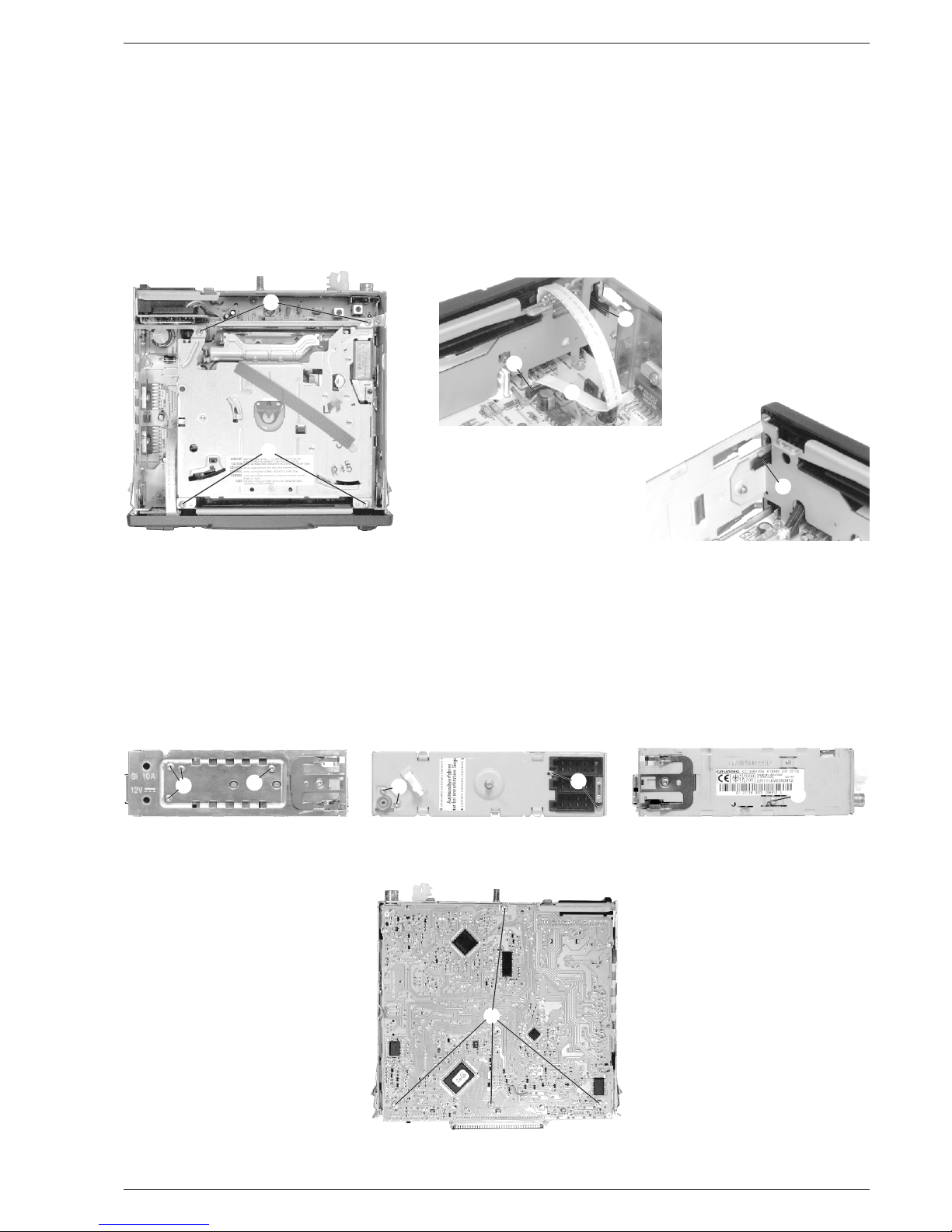
Ausbauhinweise
1. CD-Laufwerk ausbauen
- Boden und Deckel abnehmen.
- 4 Schrauben A herausschrauben (Fig. 1).
- Laufwerk vorsichtig anheben und die 2 Steckverbindungen unter
dem Laufwerk öffnen.
2. Frontblende abnehmen
- CD-Laufwerk ausbauen (Pkt. 1).
- Flachbandleitung B aus dem Stecker C herausziehen (Fig. 2).
- 2 Rastnasen D (Fig. 2) und E (Fig. 3) ausrasten und Frontblende
abnehmen.
3. Hauptplatte ausbauen
- CD-Laufwerk ausbauen (Pkt. 1).
- Frontblende abnehmen (Pkt. 2).
- 4 Schrauben F (Fig. 4) herausschrauben.
- 4 Schrauben G (Fig. 5) herausschrauben.
- Schraube H (Fig. 6) herausschrauben.
- 4 Schrauben J (Fig. 7) herausschrauben.
- Hauptplatte herausnehmen.
3. Removing the Main Board
- Remove the CD Drive (para 1).
- Remove the Front Mask (para 2).
- Undo 4 screws F (Fig. 4).
- Undo 4 screws G (Fig. 5).
- Undo screw H (Fig. 6).
- Undo 4 screws J (Fig. 7).
- Remove the Main Board.
Disassembly Instructions
1. Removing the CD Drive
- Remove top and bottom cover.
- Undo 4 screws A (Fig. 1).
- Lift the CD Drive carefully and unplug the 2 connectors below the
drive.
2. Removing the Front Mask
- Remove the CD Drive (para 1).
- Pull out the flexprint B from the connector C (Fig. 2).
- Unhook the 2 catches D (Fig. 2) and E (Fig. 3) and remove the Front
Mask.
Page 4
Allgemeiner Teil / General Section SCD 3390 RDS / Challenge 600 CD
1 - 4 GRUNDIG Service
1
2
Fig. 8 Fig. 10
Fig. 9
K
L
L
M
M
N
Fig. 11
Q
Q
Q
O
P
R
S
T
U
V
N
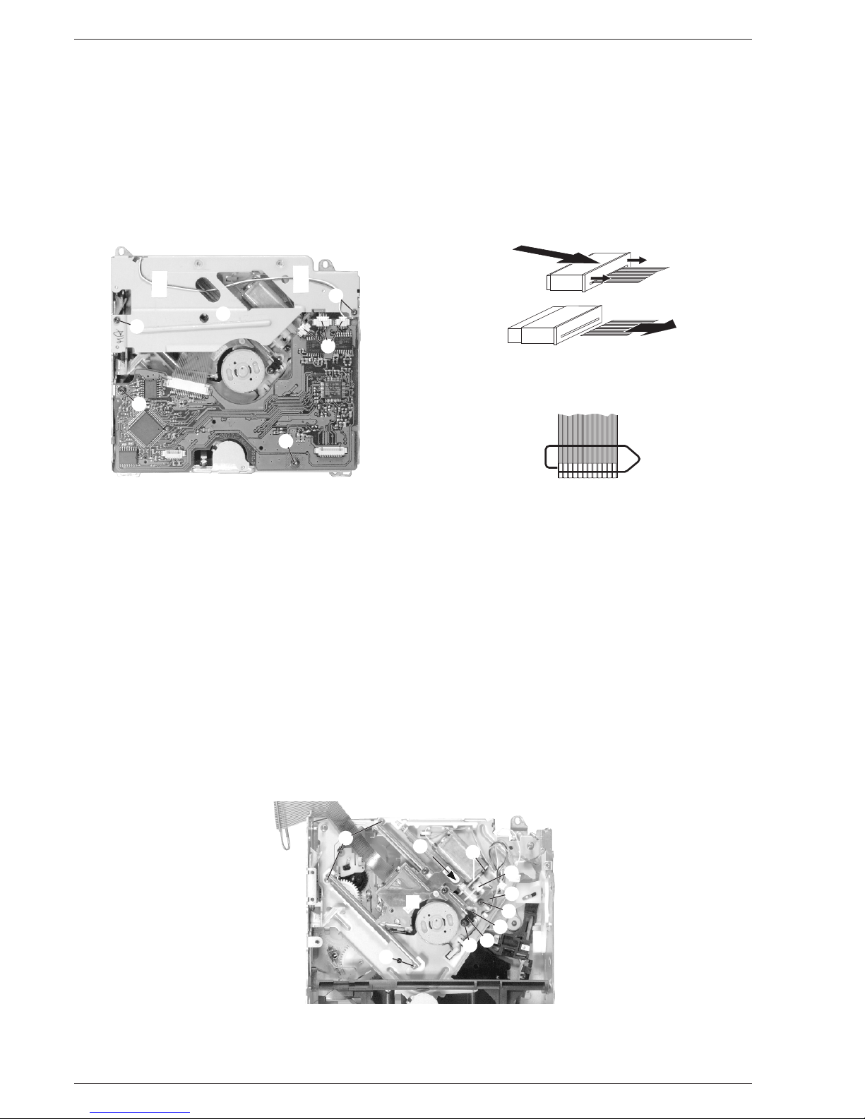
4. CD-Leiterplatte ausbauen
- CD-Laufwerk ausbauen (Pkt. 1).
- 3 Steckverbinder K abziehen (Fig. 8).
- 2 Schrauben L herausschrauben (Fig. 8).
- Leiterplatte aus der Halterung ziehen und vorsichtig (Flexprint!)
anheben.
- Flexprinthalter öffnen 1 (Fig. 9).
- Achtung: Die Lasereinheit ist sehr empfindlich gegen stati-
sche Aufladungen (MOS-Bauteile)!
Schließen Sie deshalb die Flexprintleitung zur Lasereinheit vor
dem Abziehen mit einer Büroklammer kurz (Fig. 10).
- Flexprint aus dem Flexprinthalter ziehen 2 (Fig. 9).
5. Pick-Up-Einheit ausbauen
- CD-Laufwerk ausbauen (Pkt. 1).
- CD-Leiterplatte ausbauen (Pkt. 4).
- 2 Schrauben M herausschrauben und Abdeckung N abnehmen
(Fig. 8).
- Schraube O herausschrauben und den Schalter P abnehmen
(Fig. 11).
- 4 Schrauben Q herausschrauben (Fig. 11) und die Pick-Up-Einheit
herausnehmen.
6. Schlitten-Motor ausbauen
- CD-Laufwerk ausbauen (Pkt. 1).
- Pick-Up-Einheit ausbauen (Pkt. 5).
- Schraube R herausschrauben und die Blattfeder S herausnehmen
(Fig. 11).
- Spindel T und Zahnrad U in Pfeilrichung herausziehen (Fig. 11).
- 2 Schrauben V (Fig. 11) herausschrauben und den Motor abnehmen.
4. Removing the CD PCB
- Remove the CD Drive (para 1).
- Open 3 connectors K (Fig. 8).
- Undo 2 screws L (Fig. 8).
- Pull the PCB out of its holder and lift it carefully (flexprint!).
- Open the flexprint holder 1 (Fig. 9).
- Attention: The laser unit is very sensitive to static charges
(MOS components)!
Therefore, short-circuit the flexprint to the laser unit with a metal
paper clip before disconnecting it (Fig. 10).
- Pull the flexprint out of its holder 2 (Fig. 9).
5. Removing the Pick Up Unit
- Remove the CD Drive (para 1).
- Remove the CD PCB (para 4).
- Undo 2 screws M and remove the cover N (Fig. 8).
- Undo screw O and take away the switch P (Fig. 11).
- Undo 4 screws Q and remove the Pick Up Unit.
6. Removing the Sled Motor
- Remove the CD Drive (para 1).
- Remove the Pick Up Unit (para 5).
- Undo screw R and remove the plate spring S (Fig. 11).
- Pull out the spindle T and the gear wheel U in direction of the arrow
(Fig. 11).
- Undo 2 screws V (Fig. 11) and remove the motor.
Page 5
SCD 3390 RDS / Challenge 600 CD Allgemeiner Teil / General Section
GRUNDIG Service 1 - 5
Fig. 16
Fig. 15
B B
Fig. 12
W
Fig. 13
X XY
Z
A
Fig. 14
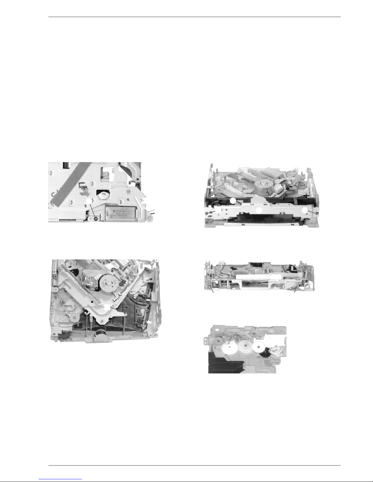
7. CD-Einzugmotor ausbauen
- CD-Laufwerk ausbauen (Pkt. 1).
- Schraube W (Fig. 12) herausschrauben und den Motor herausnehmen.
8. CD-Einzugmechanik ausbauen
- CD-Laufwerk ausbauen (Pkt. 1).
- CD-Einzugmotor ausbauen (Pkt. 7).
- 2 Schrauben X herausschrauben und die Platte Y abnehmen
(Fig. 13).
- Kunststoffteil Z ausrasten und abnehmen (Fig. 13).
- 2 Schieber A (Fig. 14) gleichzeitig nach aussen drücken und die
Mechanik nach hinten schieben.
- 2 Federn B (Fig. 15) aushängen und die Mechanik herausnehmen.
9. Zahnräder ausbauen
- CD-Laufwerk ausbauen (Pkt. 1).
- CD-Einzugmechanik ausbauen (Pkt. 8).
- Sicherungsscheiben abnehmen und die Zahnräder abnehmen
(Fig. 16).
7. Removing the Loading Motor
- Remove the CD Drive (para 1).
- Undo screw W (Fig. 12) and remove the motor.
8. Removing the Loading Mechanics
- Remove the CD Drive (para 1).
- Remove the Loading Motor (para 7).
- Undo 2 screws X and remove the plate Y (Fig. 13).
- Unhook the plastic part Z and remove it (Fig. 13).
- Push the 2 sliders A (Fig. 14) simultaneously apart and push the
mechanics backwards.
- Unhinge the 2 springs B (Fig. 15) and remove the mechanics.
9. Removing the gear wheels
- Remove the CD Drive (para 1).
- Remove the Loading Mechanics (para 8).
- Remove the washers and the gear wheels (Fig. 16).
Page 6
Allgemeiner Teil / General Section SCD 3390 RDS / Challenge 600 CD
1 - 6 GRUNDIG Service
Bedienhinweise Dieses Kapitel enthält Auszüge aus der Bedienungsanleitung. Weitergehende Informationen entnehmen Sie bitte der gerätespezifischen Bedienungsanleitung, deren Sachnummer Sie in
der entsprechenden Ersatzteilliste finden.
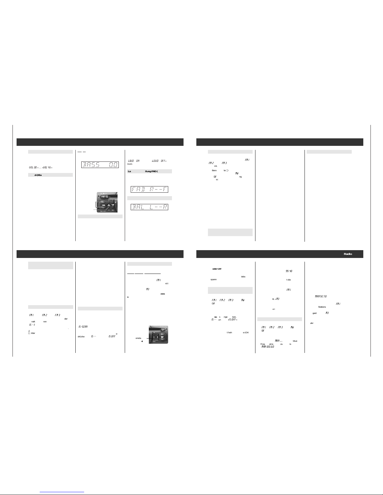
Lautstärke- und Klangeinstellung
Beispiel: Bässe einstellen
Taste
¢¢
SOUND so oft kurz drücken, bis im
Anzeigefeld erscheint:
Mit den Tasten Q
VOLUME Wkönnen Sie jetzt
den Eindruck der Baßwiedergabe verändern.
Möchten Sie die Einstellung der Baßwiedergabe sofort in Mittelstellung zurücksetzen:
Taste
¢¢
SOUND
so lange drücken
, bis der
Signalton zu hören ist.
LOUD (Loudness)
Eingeschaltete Loudness bewirkt eine Klangverbesserung bei geringer Lautstärke.
Sie können die Funktion aus der Grundstellung heraus ein- und ausschalten.
Lautstärke (Volume)
Mit den Tasten
Q
VOLUME W
die gewünschte
Lautstärke einstellen.
Im Anzeigefeld erscheint:
»
VOL 00
« … »
VOL 46
«.
Sound-(Klang-) Einstellungen
Für jede der Einstellungen FADER, BASS,
TREBLE, BALANCE gilt:
1. Funktionen durch ein- oder mehrmaliges
kurzes Drücken der Taste
¢¢
SOUND
anwählen.
2. Stellen Sie den gewünschten Klangeindruck
mit den Tasten Q
VOLUME Wein
oder
Grundeinstellung wählen:
¢¢
SOUND so lan-
ge drücken, bis der Signalton zu hören ist.
3. Einstellung beenden:
¢¢
SOUND so oft
drücken, bis der eingestellte Sender wieder
angezeigt wird.
66 Nach ca. 10 Sekunden wird die Bedien-
ebene mit aktuellen Einstellungen automatisch verlassen.
Drücken Sie die Taste
¢¢
SOUND so lange, bis
Sie zwei Signaltöne hören. Im Anzeigefeld
sehen Sie
»
LOUD ON
« (ein) oder »
LOUD oFF
«
(aus).
Lautstärkeverteilung FAD (Fader)
Mit dem Fader verändern Sie die „Lautstärkeverteilung“ zwischen vorderer („F“ Front) und
hinterer („R“ Rear) Lautsprechergruppe.
Lautstärkeverhältnis BAL (Balance)
Balance ist das „Lautstärkeverhältnis“ zwischen den Lautsprechern links und rechts.
Tasten
Q
VOLUME W
Taste
¢¢
SOUND
INTELLIGENT
SEARCH
Radio (Tuner)
Bereich wählen
FM(UKW)-Bereich:
¢¢
RADIO-T
aste
so oft kurz
drücken, bis der gewünschte Bereich »
FM I
«,
»
FM 2
« oder »
FM 3
« im Anzeigefeld
erscheint.
AM-Bereich: Taste
¢¢
RADIO so oft kurz
drücken, bis im Anzeigefeld »MW« (Mittelwelle)
oder »lW« (Langwelle) und die eingestellte Frequenz erscheint. Mittel- und Langwelle bilden
einen durchgehenden Bereich, es ist daher keine Umschaltung erforderlich.
Last Station Memory
Nachdem Sie den Bereich gewählt haben,
hören Sie den zuletzt eingestellten Sender/
Programm (Last Station Memory) in diesem
Bereich. Last Station Memory bedeutet, Ihr
Gerät merkt sich die Einstellungen, die Sie
gewählt haben, bevor Sie das Gerät ausschalten. Nach dem Wiedereinschalten hören Sie
diesen Sender, bzw. TAPE/CD wieder.
Stereo-Empfang (nur bei FM)
Sie empfangen einen Stereo-Sender, wenn
»
)« im Anzeigefeld erscheint.
Durchsagebereitschaft für Verkehrsfunk-Durchsagen (TP)
TP (TRAFFIC PROGRAM) = Verkehrsfunksender.
TP ein-/ausschalten:
¢¢
TP -Taste kurz drücken
.
Durchsagebereitschaft eingeschaltet: Das
Zeichen »TP« wird angezeigt.
66 Ist der eingestellte Sender kein Verkehrs-
funksender, startet automatisch ein Suchlauf zum nächsten Verkehrsfunksender.
Aktuelle Verkehrsfunk-Durchsage abbrechen:
¢¢
TP -Taste kurz drücken. Die Durchsagebe-
reitschaft für Verkehrsfunk bleibt erhalten.
Verkehrsfunk-Durchsagen beginnen mit
einer Mindestlautstärke:
Im EXPERT-Bedienmenü können Sie die Mindestlautstärke, mit der Verkehrsfunk-Durchsagen zu hören sind, verändern, siehe Seite 14,
EXPERT
§?.
66 Möchten Sie nur Verkehrsfunk-Durchsagen
hören, dann aktivieren Sie die Funktion
„Durchsagebereitschaft für Verkehrsfunkdurchsagen“ mit der Taste
¢¢
TP und stellen
die Lautstärke mit der Taste W
VOLUME auf
"Null".
66 Auch die CD-Wiedergabe wird während der
Verkehrsfunk-Durchsage unterbrochen.
Alternative Frequenzen (AF)
Wenn Sie ein RDS-Programm empfangen,
das von mehreren Sendern mit unterschiedlichen Frequenzen ausgestrahlt wird, dann
wechselt Ihr Autoradio automatisch auf die
am besten zu empfangende Frequenz.
66 Wenn Sie sich in einem sehr schlecht ver-
sorgten Empfangsgebiet aufhalten, können
Wechselversuche zwischen AF´s als
störende Pausen hörbar werden. In einem
solchen Fall kann die AF-Funktion ausgeschaltet werden.
Im Auslieferungszustand ist AF aktiviert.
AF-Funktion ausschalten
Dies ist nur bei Sendern mit Alternativfrequenzen möglich.
¢¢
TP - Taste länger drücken, bis der Signalton
zu hören ist.
Das Zeichen »AF« wird nicht mehr angezeigt.
AF-Funktion wieder einschalten
¢¢
TP - Taste länger drücken, bis der Signalton
zu hören ist.
Das Zeichen »AF« wird angezeigt.
Radio
Stationstasten
¢¢1,¢¢2,¢¢3,¢¢
4
Bereich wählen: FMl, FM ll, MW oder LW.
Sender
/RDS-Programm einstellen:
66 Ist der eingestellte Sender/RDS-Programm
im gewählten Bereich, z.B. »
FM I
«, bereits
auf einer Stationstaste gespeichert, wird im
Anzeigefeld “M” und die entsprechende Ziffer
dargestellt, z.B. »
M3
« für Speicherplatz 3.
Eingestellten Sender/RDS-Programm
speichern:
Stationstaste so lange drücken, bis der Signalton zu hören ist.
66 Die gewählte AF-Einstellung wird zusam-
men mit der Station abgespeichert.
RDS-Programme einstellen
(IS-Funktion)
Mit einem Tastendruck können Sie im IS-Speicher bis zu 30 Programme speichern. Die gespeicherten Programme können Sie nacheinander aufrufen, siehe “Wissenswertes” Seite 18.
66 Die Benutzung des IS-Speichers ist sinn-
voll, wenn Sie die Stationstasten neu belegen wollen oder sich in einem fremden
Empfangsbereich aufhalten und die schon
gespeicherten Sender nicht löschen
möchten.
IS-Suchlauf auslösen
Wählen Sie mit Taste
¢¢
RADIO/IS den Bereich
»
FM 1
«, oder »
FM 2
« oder »
FM 3
«.
Drücken Sie die Taste
¢¢
RADIO/IS, bis der erste
Signalton zu hören ist:
»
IS --)
« erscheint im Anzeigefeld, der
Empfänger durchsucht den UKW-Bereich.
66 Warten Sie stets, bis der intelligente Such-
lauf (IS) beendet ist.
66 Ist kein Empfang möglich, kann der Such-
lauf ständig aktiv sein, z. B. in der Tiefgarage oder bei defekter Antenne. In diesem
Fall können Sie den Suchlauf durch Drücken
einer der Stationstasten
¢¢
1 … ¢¢4 ab-
brechen (siehe auch Seite 19).
Sobald der IS-Suchlauf abgeschlossen ist,
sind bis zu 30 Sender gespeichert und Sie
hören den Sender mit dem bestem Empfang.
Beim intelligenten Suchlauf werden zuerst die
RDS-Programme gespeichert (sortiert nach
Programmen), dann die übrigen Sender nach
der Sendestärke.
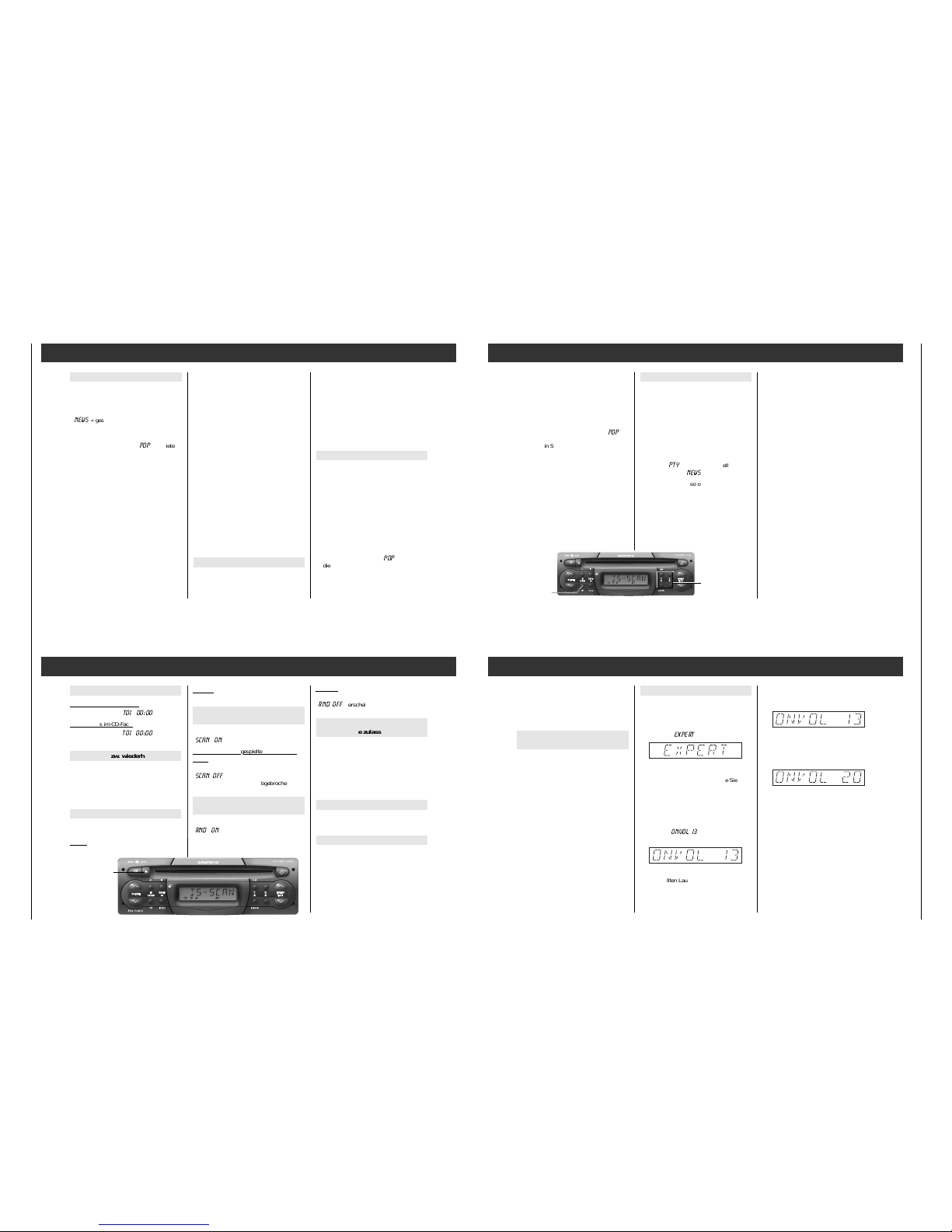
Inhalt des IS-Speichers abrufen
Nach einem erfolgreichen IS-Suchlauf wählen
Sie mit
einer der Tasten
Q
TUNING W
Ihren
gewünschten Sender
.
Im Anzeigefeld ist während der Stationswahl
»
IS-SCAN
« zu sehen.
Betriebsart IS ausschalten:
Dazu eine der Tasten Q
TUNING Wso lange
drücken, bis »
IS --
« und dann »
IS OFF
« kurz
erscheint.
Der Sendersuchlauf ist auf Seite 8 beschrie-
ben.
Stationstasten
¢¢
1 … ¢¢4
Radio
66 Bei stetigem Drücken einer der Tasten
Q
TUNING Werfolgt die Fortschaltung im
Schnellgang.
3. Stellen Sie mit den Tasten
Q
TUNING Wdie Frequenz in der gewünsch-
ten Richtung ein. Mit Q
TUNING erhöhen Sie
die Frequenz bei FM um jeweils 50 kHz, bei
AM um jeweils 1 kHz. Mit W
TUNING
verringern Sie die Frequenz jeweils um den
gleichen Wert. Im Anzeigefeld sehen Sie
z.B. »
MAN 92.70
«.
66 Ist der eingestellte Sender/RDS-Programm
im gewählten Bereich, z.B. »
FM I
«, bereits
auf einer Stationstaste gespeichert, wird im
Anzeigefeld “M” und die entsprechende Ziffer
dargestellt, z.B. »
M3
« für Speicherplatz 3.
4. Wenn Sie den eingestellten Sender auf
einer Stationstaste speichern möchten, verfahren Sie wie in Abschnitt “Stationstasten”
beschrieben (siehe Seite 7).
5. Manuelle Frequenzeinstellung beenden:
Taste
¢¢
RADIO kurz drücken.
66 Wenn Sie 60 Sekunden keine Taste
drücken, wird die manuelle Frequenzeinstellung automatisch beendet.
2.
Durch kurzes Drücken einer der Tasten
Q
TUNING Wkönnen Sie den Suchlauf in die
gewünschte Richtung starten. Im Anzeigefeld ist die Frequenz z.B. »
99.40
«zu
sehen. Wenn ein Sender mit Namens-Kennung gefunden ist, sehen Sie die Kennung
im Anzeigefeld, sonst bleibt die Frequenzanzeige.
66 Ist der eingestellte Sender/RDS-Programm
im gewählten Bereich, z.B. »
FM I
«, bereits
auf einer Stationstaste gespeichert, wird im
Anzeigefeld “M” und die entsprechende Ziffer
dargestellt, z.B. »
M3
« für Speicherplatz 3.
3. Wenn Sie den eingestellten Sender auf
einer Stationstaste speichern möchten, verfahren Sie wie in Abschnitt “Stationstasten”
beschrieben (siehe Seite 7).
Manuelle Frequenzeinstellung
1. Bereich mit der Taste
¢¢
RADIO wählen:
»
FM I
«, »
FM 2
«, »
FM 3
« oder »MW« bzw.
»LW«.
2. Drücken Sie eine der Tasten
Q
TUNING Wso lange, bis Sie zwei Signaltö-
ne hören und »
MAN ...
« mit der aktuellen
Frequenzeinstellung zu sehen ist, z.B.
»
MAN 100.60
«.
Gespeicherte Sender/RDS-Programme
abrufen: Bereich wählen: FMl, FM 2, FM3,
MW oder LW.
Stationstaste kurz drücken.
66 Auch nach Abklemmen der Betriebs-
spannung bleiben die Speicherinhalte der
Stationstasten erhalten.
Sender/RDS-Programme mit Sendersuchlauf einstellen
1. Bereich mit der Taste
¢¢
RADIO wählen:
»
FM I
«, »
FM 2
«, »
FM 3
« oder »MW« bzw.
»LW«.
Um einen Suchlauf im Bereich FM zu starten muß die Betriebsart IS ausgeschaltet
sein (siehe Seite 7). Dazu eine der Tasten Q
TUNING Wso lange drücken, bis
»
IS --
« und dann »
IS OFF
« kurz erscheint.
66 Der Suchlauf in den FM-Bereichen arbeitet
mit zwei Empfindlichkeitsstufen. Im ersten
Durchlauf durch den Empfangsbereich wird
nach Sendern mit hoher Feldstärke (Ortssender), im zweiten Durchlauf nach Sendern mit geringer Feldstärke (Fernempfang)
gesucht.
66 Bei Sendersuche wird im AM-Bereich
zuerst das LW-, dann das MW-Band durchsucht.
Page 7
SCD 3390 RDS / Challenge 600 CD Allgemeiner Teil / General Section
GRUNDIG Service 1 - 7
Radio
Programmtypen (PTY)
Viele Rundfunkanstalten bieten im UKWBereich (FMl, FMll) den Service "Programmtypen" (PTY) an. Während einer Nachrichtensendung wird beispielsweise die Kennung
»
NEWS
« gesendet.
Mit dem PTY-Suchlauf kann automatisch ein
Sender eingestellt werden, der einen vorgewählten Programmtyp z.B. »
POP
« anbietet.
Programmtypen
Die angebotenen Programmtypen einer
Rundfunkanstalt können je nach gesendetem
Programm wechseln.
NEWS Nachrichten und Aktuelles
AFFAIRS Politik und Zeitgeschehen
INFO Spezielle Wortprogramme
SPORT Sportsendungen
EDUCATE Lernen und Weiterbildung
DRAMA Hörspiel und Literatur
CULTURE Kultur, Kirche und Gesellschaft
SCIENCE Wissenschaft
VARIED Unterhaltendes Wort
POP Popmusik (Hits und Schlager)
ROCK M Rockmusik
EASY M Leichte Musik
LIGHT M Leichte klassische Musik
CLASSICS Ernste klassische Musik
OTHER M Musikprogramme die sich nicht
zuordnen lassen (z.B. Folklore)
WEATHER Wetterberichte
FINANCE Wirtschaftsnachrichten
CHILDREN Kindersendungen
SOCIAL A Soziale Informationen
RELIGION Religiöse und philosophische
Sendungen
PHONE IN Hörertelefon
TRAVEL Touristeninformation
LEISURE Freizeit, Hobby und Zeitvertreib
JAZZ Jazz-Musik
COUNTRY Country-Musik
NATIONAL Nationale Sendungen
OLDIES Golden Oldies
FOLK M Volksmusik
DOCU Tatsachen-Berichte
NO PTY Keine Programmtyp-Kennung
PTY-Suchlauf
66 Für die Wahl eines Programmtyps haben
Sie zwei Möglichkeiten zum Aufrufen des
Suchlaufs.
1. Den vier PTY-Programm-Tasten (Stationstasten) sind vier Programmtypen zugeordnet. Sie können diese voreingestellte Zuordung nach Ihren Wünschen ändern.
2. Sie können einen Programmtyp aus der
gespeicherten Liste wählen und dann den
Suchlauf starten.
Die Vorgehensweise wird in den folgenden
Abschnitten erklärt.
PTY-Funktion
1. PTY-Funktion einschalten
¢¢
PTY -Taste so lange drücken, bis der
Signalton zu hören ist:
der zuletzt gewählte Programmtyp wird
angezeigt.
2. Programmtyp einstellen …
– mit den Tasten
¢¢
1 … ¢¢4
Taste kurz drücken:
PTY-Suchlauf startet automatisch zum
nächsten Sender, der den vorgewählten
Programmtyp anbietet und zeigt kurze Zeit
den Programmtyp, z.B. »
POP
«, danach
die Bezeichnung des eingestellten Senders
– oder –
Radio
– Tasten QTUNINGWso oft drücken, bis der
gewünschte Programmtyp im Anzeigefeld
erscheint.
Eine der Tasten Q
TUNING Wso lange
drücken, bis der Signalton zu hören ist:
PTY-Suchlauf startet zum nächsten Sender,
der den gewählten Programmtyp anbietet
und zeigt den Programmtyp, z.B. »
POP
«.
66 Bietet kein Sender den gewählten
Programmtyp an, hören Sie den zuletzt
eingestellten Sender und die PTY-Funktion
wird verlassen.
3. PTY-Funktion abschalten
¢¢
PTY -Taste kurz drücken oder
automatisch nach ca. 10 Sekunden.
PTY-Programm-Tasten belegen
Die Stationstasten
sind werkseitig mit den Programmtypen:
¢¢
1NEWS,¢¢2 SPORT, ¢¢3 POP und
¢¢
4 CLASSICS belegt.
Sie können jede der Stationstasten mit einem
Programmtyp Ihrer Wahl belegen:
1. PTY-Funktion einschalten:
¢¢
PTY -Taste so lange drücken, bis der Si-
gnalton zu hören ist. Im Anzeigefeld sehen
Sie kurz »
PTY
« und den eingestellten Pro-
grammtyp, z.B. »
NEWS
«.
2. Tasten Q
TUNING Wso oft drücken, bis der
gewünschte Programmtyp im Anzeigefeld
erscheint.
3. Gewünschte Stationstaste z.B.
¢¢
1 so lange
drücken, bis der Signalton zu hören ist.
PTY-Taste
SCD 3390 RDS
INTELLIGENT
SEARCH
Stationstasten
¢¢
1 … ¢¢4
CD-Betrieb
Programmquelle CD wählen
CD ins CD-Fach einschieben.
Im Display erscheint »
T01 00:00
«. – oder –
CD ist bereits im CD-Fach:
Taste
¢¢
CD drücken, »
T01 00:00
« ercheint
im Display.
Titel wählen bzw. wiederholen
Taste QTRACK: nächste Titel
Taste W
TRACK: vorherige Titel bzw.
den Titel, den Sie hören, wiederholen.
Tasten (so oft) kurz drücken, bis die Nummer
des gewünschten Titels im Display erscheint.
Vorlauf und Rücklauf
Titel im "Schnelldurchgang" mit
reduzierter Lautstärke hören:
Vorlauf
: Taste Qdrücken und gedrückt
halten.
Rücklauf: Taste Wdrücken und gedrückt
halten.
Titel der CD für ca. 10 Sekunden
anspielen (TRACK SCAN)
Taste
¢¢
SCAN kurz drücken:
»
SCAN ON
« erscheint kurz im Display.
Möchten Sie den an
gespielten Titel zu Ende
hören:
Taste
¢¢
SCAN kurz drücken:
»
SCAN OFF
« erscheint kurz im Display.
Die SCAN-Funktion ist nun abgebrochen.
Titel der CD in zufälliger Reihenfolge
(TRACK RANDOM)
Taste
¢¢
RANDOM kurzdrücken:
»
RND ON
« erscheint kurz im Display.
Beenden:
Taste
¢¢
RANDOM kurzdrücken:
»
RND OFF
« erscheint kurz im Display.
Verkehrsfunk-Durchsagen während
CD-Wiedergabe zulassen
TP einschalten
Taste
¢¢
TP kurz drücken:
»TP« erscheint im Display.
TP ausschalten
Taste
¢¢
TP kurz drücken:
»TP« erlischt im Display.
CD-Betrieb beenden
Taste
¢¢
RADIO kurz drücken
oder lassen Sie die CD ausschieben.
CD ausschieben
Taste . kurz drücken.
Die CD wird ausgeschoben.
Wird die ausgeschobene CD nicht innerhalb
von 15 Sekunden entnommen, wird sie aus
Sicherheitsgründen wieder eingezogen.
SCD 3390 RDS
INTELLIGENT
SEARCH
CD ausschieben
EXPERT-Bedienebene
Damit die Bedienung des Autoradios so
einfach wie möglich ist, befinden sich eine
Vielzahl von Einstellungen, die Sie nur einmal
oder nur gelegentlich brauchen, in einer
zusätzlichen Bedienebene (EXPERT).
Liste der möglichen
Expert-Einstellungen
1 Code-Einstellungen
2 Kontrast des Anzeigefeldes
3 Security-Leuchtanzeige Ein/Aus
4 Signalton Ein/Aus
5 AM-Bereich sperren
6 Automatischer Verkehrsfunk-Suchlauf
Ein/Aus
7 Automatischer Wechsel des Regional-
programmes Ein/Aus
8 Ein- und Ausschalten mit dem Zünd-/
Anlaßschalter
9 Stummschaltung bei Autotelefon-Betrieb
§I Lautstärkebegrenzung beim Einschalten
§? Mindestlautstärke für Verkehrsfunk-
Durchsagen
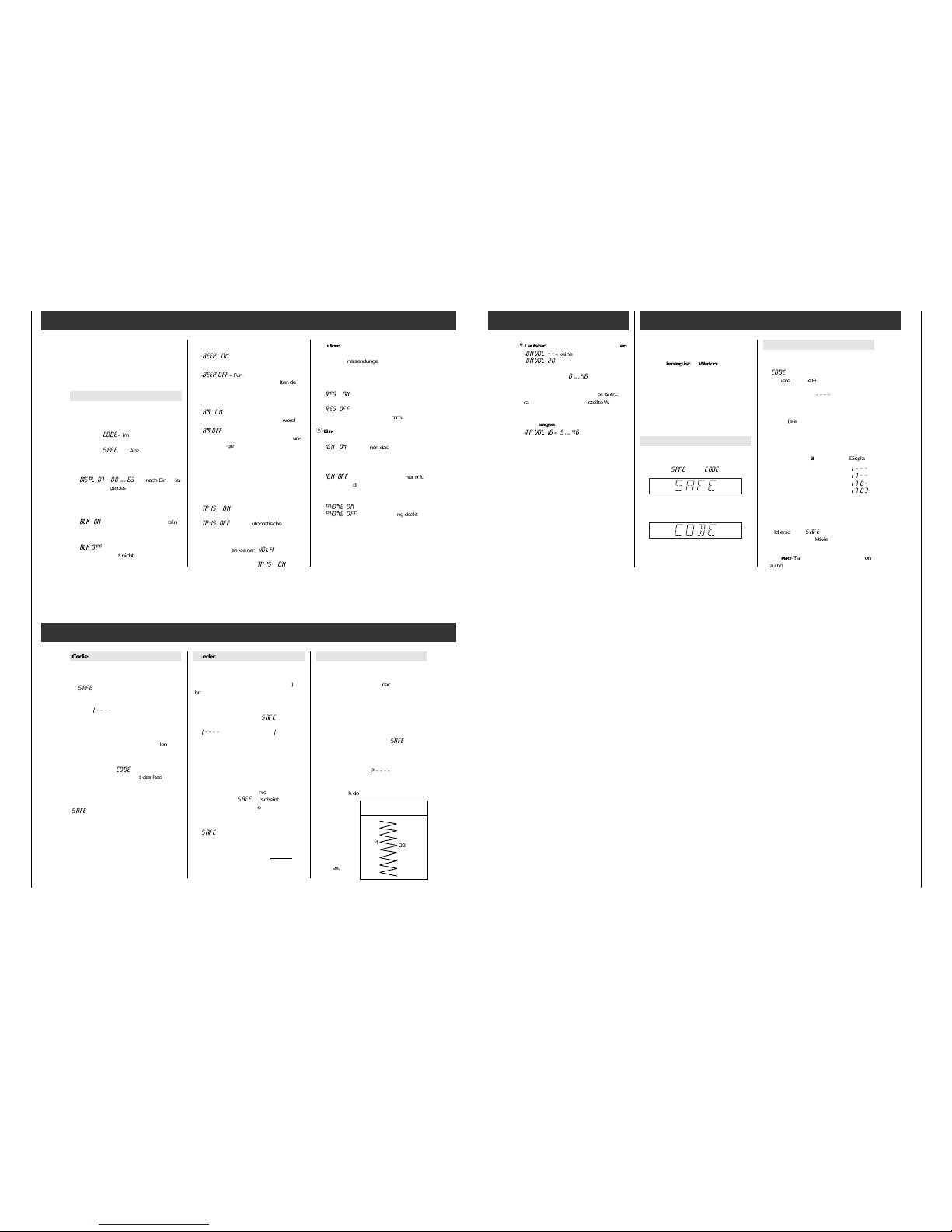
Expert-Einstellungen ändern
1. EXPERT einschalten
¢¢
EXPERT- Taste so lange drücken, bis der
Signalton zu hören ist. Im Anzeigefeld sehen Sie kurz
»
EXPERT
«.
2. Einstellung wählen
Wählen Sie mit den Tasten
Q
TUNING Wdie Einstellung aus, die Sie über-
prüfen, bzw. verändern wollen
Beispiel:
§I Ändern der Lautstärkebegrenzung beim
Einschalten
Mit den Tasten Q
TUNING W, die gewünschte
Funktion »
ONVOL 13
« einstellen, im Anzei-
gefeld erscheint:
Sie hören den gewählten Sender mit der
eingestellten Lautstärke.
3. Einstellung aktivieren
Taste
¢¢
EXPERT kurz drücken:
Die Anzeige blinkt.
4. Einstellung verändern
Stellen Sie mit den Tasten
QTUNING Wdie gewünschte Lautstärke ein.
Im Anzeigefeld erscheint z. B.:
Q
TUNING : Wert erhöhen oder
Funktion einschalten,
W
TUNING : Wert verringern oder
Funktion ausschalten.
Sie können durch mehrmaliges Drücken der
Taste den Wert schrittweise ändern oder
durch längeres Drücken den automatischen
Schnelldurchlauf nutzen.
5. Einstellung beenden
Taste
¢¢
EXPERT kurz drücken:
Die Anzeige erscheint wieder dauerhaft.
Page 8
Allgemeiner Teil / General Section SCD 3390 RDS / Challenge 600 CD
1 - 8 GRUNDIG Service
EXPERT
6. Nächste Einstellung wählen
(Punkt 2. bis 5. wiederholen)
7. EXPERT ausschalten
¢¢
EXPERT-Taste länger drücken, bis der
Signalton zu hören ist.
Mögliche Einstellungen 1…§?
1
Codierung aktivieren (eine genaue Anleitung finden Sie im Kapitel »Codierung«,
Seite 16)
Erscheint »
CODE
« im Anzeigefeld, ist die
Codierung nicht aktiviert.
Erscheint »
SAFE
« im Anzeigefeld, ist die
Codierung aktiviert.
2 Kontrast des Anzeigefeldes
»
DISPL 07
« (
00 ... 63
), je nach Einbaulage des Autoradios so einstellen, daß das Anzeigefeld für
Sie gut ablesbar ist.
3 Security-Leuchtanzeige (Ein/Aus)
»
BLK ON
« Die Security-Leuchtdiode blinkt
bei ausgeschaltetem Gerät und
ausgeschalteter Zündung.
»
BLK OFF
« Die Security-Leuchtdiode
blinkt nicht.
4 Signalton (Ein/Aus)
»
BEEP ON
« Signalton als Funktionsbe-
stätigung.
»
BEEP OFF
« Funktionsbestätigung durch
kurzes Stummschalten der
Lautsprecher-Ausgänge.
5 AM-Bereich (Ein/Aus)
»
AM ON
« Der AM-Bereich kann mit der
Taste
¢¢
RADIO gewählt werden.
»
AM OFF
« Beim Umschalten zwischen den
Bereichen wird AM übersprungen.
6 TP-IS (Radio-Betrieb)
Wenn Sie sich in einem Empfangsgebiet
aufhalten, in denen Sie RDS-Programme
mit Verkehrsfunk schlecht empfangen,
können Sie die automatische Sendersuche
im Radio-Betrieb verhindern.
»
TP-IS ON
« automatische Verkehrsfunk-
Sendersuche gewünscht,
»
TP-IS OFF
« keine automatische Ver-
kehrsfunk-Sendersuche
gewünscht.
66 Bei Lautstärken kleiner »
VOL 4
« aus Komfortgründen die autonatische VerkehrsfunkSendersuche aktiviert (»
TP-IS ON
«).
7 Autom. Wechsel des Regionalprogramms
Wenn ein RDS-Programm aus verschiedenen Regionalsendungen besteht, kann es
vorkommen, daß Ihr Autoradio aufgrund
des Empfangsgebietes zwischen verschiedenen Regionalsendungen wechselt.
»
REG ON
« autom. Wechsel des Regio-
nalprogramms ist möglich.
»
REG OFF
« kein Wechsel auf ein anderes
Regionalprogramm.
8 Ein- und Ausschalten mit dem
Zünd-/Anlaßschalter
»
IGN ON
« Sie können das Autoradio mit
dem Zünd-/Anlaßschalter des
Fahrzeuges ein- und ausschalten.
»
IGN OFF
« Ein- und Ausschalten nur mit
der
¡
IO
-Taste.
9 Stummschaltung bei Telefon-Betrieb
»
PHONE ON
« Stummschaltung aktiviert.
»
PHONE OFF
« Stummschaltung deakti-
viert.
66 Das Telefon-Mutesignal muß in diesem Fall
angeschlossen sein.
Codierung
§I Lautstärke-Begrenzung beim Einschalten
»
ONVOL - -
« keine Begrenzung oder
»
ONVOL 20
« max. Lautstärke, z.B. 20
(Einstellbereich:
- - (
0 ... 46
).
Die Lautstärke wird nur begrenzt, wenn die
Lautstärke beim Ausschalten des Autoradios größer als der eingestellte Wert ist!
§? Mindestlautstärke für Verkehrsfunk-
Durchsagen
»
TA VOL 16
« (
5 ... 46
)
Sie hören während der Einstellung die dann
für die Verkehrsfunkdurchsage gewählte
Lautstärke.
66 Die Code-Nummer Ihres Autoradios befin-
det sich auf der Identity Card.
Die Codierung ist ab Werk nicht aktiviert.
Wenn Sie die Codierung Ihres Autoradios
aktiviert haben:
Sobald das Autoradio von der Autobatterie
(bzw. Dauerplus Klemme 30) Ihres Fahrzeugs getrennt wird, ist es elektronisch
gesichert.
Es kann nur durch Eingabe der Code-Nr.
wieder in Betrieb genommen werden.
Ist die Codierung aktiviert?
Wählen Sie die EXPERT-Bedienebene und
drücken Sie die Tasten Q
TUNING W, bis im
Anzeigefeld »
SAFE
« oder »
CODE
« erscheint:
Codierung aktiviert
Codierung nicht aktiviert
Codierung aktivieren
1. Wählen Sie die EXPERT-Bedienebene und
drücken Sie die Tasten Q
TUNING W, bis
»
CODE
« im Anzeigefeld erscheint.
Aktivieren Sie die Einstellung:
Drücken Sie die Taste
¢¢
EXPERT kurz. Im
Anzeigefeld blinkt »
- - - -
«.
2. Geben Sie die Code-Nr. (siehe Identity
Card) mit den Tasten Q
TUNING Woder
¢¢
1
…
¢¢
4 (siehe Beispiel) ein.
66 Bei längerem Drücken einer der Tasten
r
TUNING t erfolgt die Fortschaltung im
Schnellgang.
Beispiel: 1703 Display:
Taste
¢¢
1 11 x kurz drücken >
1 - - -
<
Taste
¢¢
2 17 x kurz drücken >
1 7 - -
<
Taste
¢¢
3 10 x kurz drücken >
1 7 0 -
<
Taste
¢¢
4 13 x kurz drücken >
1 7 0 3
<
Bei längerem Drücken wird die jeweilige
Ziffer rückwärts gezählt.
3. Code-Nr. bestätigen:
Taste
¢¢
EXPERT kurz drücken, im Anzeige-
feld erscheint »
SAFE
«.
Die Codierung ist aktiviert!
4. EXPERT ausschalten:
¢¢
EXPERT-Taste drücken, bis der Signalton
zu hören ist.
EXPERT
Codierung
Wartezeiten
Damit die Wiederinbetriebnahme und das
Deaktivieren der Codierung nicht durch Ausprobieren möglich ist, sind nach Fehlversuchen Wartezeiten vorgesehen. Während dieser
Zeiten läßt sich das Autoradio zwar ein- und
ausschalten, spielt aber nicht.
Während der Wartezeit
muß das Autoradio nicht eingeschaltet sein.
Es muß jedoch an Dauerspannung + 12 V
angeschlossen sein. So lange »
SAFE
« im
Anzeigefeld steht, ist die Wartezeit noch nicht
abgelaufen. Die Wartezeit ist zu Ende, wenn
die Zahl des nächsten Versuchs im Anzeigefeld zu sehen ist, z.B. »
2 - - - -
«.
Die Tabelle zeigt die Wartezeiten zwischen den
einzelnen Versuchen.
Wartezeit nach dem 7. Versuch immer
24 Stunden!
Nach dem 6. Versuch empfiehlt es
sich, "Wiederinbetriebnahme"
bzw. "Codierung
deaktivieren" von
Ihrem Fachhändler durchführen
zu lassen.
Codierung deaktivieren
z.B. vor dem Ausbau des Autoradios:
1. EXPERT-Mode ist eingeschaltet und
»
SAFE
« erscheint im Anzeigefeld.
Aktivieren Sie die Einstellung: Drücken Sie
die Taste
¢¢
EXPERT kurz. Im Anzeigefeld
blinkt »
1 - - - -
«.
2. Code-Nr. (siehe Identity Card), wie im
Kapitel "Codierung aktivieren" beschrieben,
durch Drücken der Tasten
Q
TUNING Wbzw.
¢¢
1 … ¢¢4 einstellen.
3. Code-Nr. bestätigen:
Taste
¢¢
EXPERT drücken, bis im Anzeigefeld
vorübergehend »
CODE
« erscheint.
Nach ca. 3 Sekunden spielt das Radio.
Die Codierung ist nicht mehr aktiviert!
Falls Sie eine falsche Code-Nr. eingegeben
haben:
»
SAFE
« bleibt im Anzeigefeld stehen, das
Radio spielt nicht.
Beginnen Sie nochmals. Beachten Sie die
Wartezeiten zwischen den Versuchen.
Wiederinbetriebnahme
Das Autoradio ist bei aktivierter Codierung
elektronisch gesichert, nachdem es von der
Autobatterie (bzw. Dauerplus Klemme 30)
Ihres Fahrzeugs getrennt war, z.B. nach einem
Werkstattaufenthalt.
1. Autoradio einschalten:
Im Anzeigefeld erscheint »
SAFE
«.
Nach ca. 3 Sekunden erscheint
»
I - - - -
« im Anzeigefeld. Die »I« kenn-
zeichnet die Anzahl der Eingabeversuche.
2. Code-Nr. (siehe Identity Card), wie im
Kapitel "Codierung aktivieren" beschrieben,
mit den Tasten Q
TUNING Woder
¢¢
1 … ¢¢4 eingeben.
3. Code-Nr. bestätigen:
Taste
¢¢
EXPERT drücken, bis im Anzeigefeld
vorübergehend»
SAFE
« erscheint.
Nach ca. 3Sekunden spielt das Radio.
Falls Sie eine falsche Code-Nr. eingegeben haben:
»
SAFE
« bleibt im Anzeigefeld stehen, das
Radio spielt nicht.
Beginnen Sie nochmals.
Beachten Sie die Wartezeiten zwischen
den
Versuchen.
Versuch (im Wartezeit
Anzeigefeld) (ca.)
1
21 Sek.
2
1,5 Min.
3
5,5 Min.
4
22 Min.
5
1,5 Std.
6
6,0 Std.
7
24 Std.
8
24 Std.
Page 9
SCD 3390 RDS / Challenge 600 CD Allgemeiner Teil / General Section
GRUNDIG Service 1 - 9
Operating Hints This chapter contains excerpts from the operating instructions. For further particulars please refer to the appropriate user instructions the part number of which is indicated in the relevant
spare parts list.
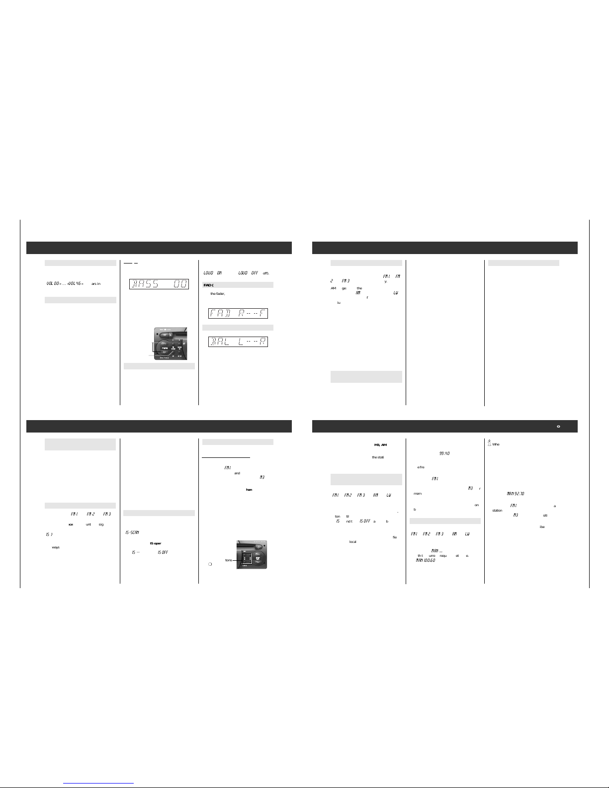
Volume and sound settings
Example: setting the bass
Press the
¢¢
SOUND repeatedly briefly until the
following appears in the display:
With the Q
VOLUME buttons Wyou can change
the impression of the bass.
If you would like to immediately change the
bass setting back to the medium setting:
Press the
¢¢
SOUND
button until
, until the sig-
nal tone can be heard.
LOUD (Loudness)
Switching the loudness on improves the
sound at low volumes.
You can switch the function on and off from
the basic setting.
Volume
Set the desired volume with the
Q
VOLUME W
buttons.
»
VOL 00
« … »
VOL 46
« appears in the dis-
play.
Sound settings
For the settings FADER, BASS, TREBLE,
BALANCE:
1. Select functions by pressing the
¢¢
SOUND
button one or more times briefly.
2. Select the desired sound impression with
the Q
VOLUME Wbuttons
or
select the basic setting:
Press
¢¢
SOUND
until the signal tone can be heard.
3. Ending the setting:
Press
¢¢
SOUND repeat-
edly until the set station is displayed again.
66 After approx. 10 seconds, the control level
with the current settings is quit automatically.
Press the
¢¢
SOUND button until you hear two
signal tones. You see
»
LOUD ON
« (on) or »
LOUD OFF
« (off).
FAD (Fader)
With the fader, you can set the “volume distribution” between the front (“F” Front) and the
rear (“R” Rear) sets of speakers.
BAL (Balance)
Balance is the “volume ratio” between the left
and right speakers.
Buttons
Q
VOLUME W
¢¢
SOUND button
INTELLIGENT
SEARCH
Radio (Tuner)
Select a range
FM range:
Press the
¢¢
RADIO button in quick
repetition until the desired range »
FM I
«, »
FM
2
« or »
FM 3
« appears in the display.
AM range: Press the
¢¢
RADIO button in quick
repetition until »AM« (medium wave) or »LW«
(long wave) and the set frequency appears.
Medium wave and long wave form a continuous range, so switching is not necessary.
Last station memory
After you have selected the range, you hear
the last station/channel (last station memory)
in this range. Last station memory means
that the system notes the settings you have
selected, before you switch the system off.
After switching back on, you hear this station
or TAPE/CD again.
Stereo reception (only for FM)
You are receiving a stereo station if
»
)« appears in the display.
Announcement stand-by for traffic
announcements (TP)
TP (TRAFFIC PROGRAM) = traffic radio station.
Switching TP on and off:
Press the
¢¢
TP-button briefly
.
Announcement stand-by switched on: The
»TP« symbol is displayed.
66 If the set station is not a traffic radio station,
a search for the next traffic radio station
begins.
Breaking off the current traffic announcement:
Press the
¢¢
TP -button briefly. The announce-
ment stand-by for traffic radio remains active.
Traffic announcements begin at a minimum
volume:
In the EXPERT operating menu, you can change
the minimum volume at which traffic announcements are heard. See page 14, EXPERT
§?.
66 If you would like to hear only traffic announ-
cements, activate the “announcement standby” function for traffic announcements with
the
¢¢
TP button and set the volume with the
W
VOLUME button at “zero”.
66 CD play is also interrupted during the traffic
announcement.
Alternative frequencies (AF)
When you receive an RDS program which is
broadcast by several stations art different frequencies, the car radio automatically switches
to the frequency with the best reception.
66 When you are in an area with very poor
reception, attempts to change between different frequencies can be heard as disturbing
pauses. In such a case, the AF function can
be switched off.
The system is delivered with AF active.
Switching off the AF function
This is only possible for stations with alternative
frequencies.
Press the
¢¢
TP-button for a longer period of
time until the signal tone can be
heard.
The »AF« symbol is no longer displayed.
Switching the AF function back on
Press the
¢¢
TP- button for a longer period of
time until the signal tone can be
heard.
The »TP« symbol is displayed.
Radio
Station buttons
¢¢1,¢¢2,¢¢3,¢¢
4
Select a range: FMl, FMll, AM or LW.
Setting the station/RDS channel:
66 If the set station/RDS channel in a selected
range, e.g. »
FM I
«, is already stored under a
station button, “M” and the corresponding
number is shown in the display e.g. »
M3
« for
memory position 3.
Storing the set station/RDS channel:
Press the station button until the signal tone
can be heard.
66 The selected AF setting is stored together
with the station.
Setting RDS channels
(IS function)
By pressing a button, you can store up to 30
channels in the IS memory. The stored channels
can be called up one after the other. See “Things
to know” page 18.
66 It is a good idea to use the IS memory, if you
would like to make new assignments to the
station buttons or if you are in a strange
reception area and do not wish to delete the
already stored stations.
Activating IS search
Select the range »
FM 1
«, or »
FM 2
« or »
FM 3
with the
¢¢
RADIO/IS button«.
Press the
¢¢
RADIO/IS button until the signal tone
can be heard.
»
IS )
« appears in the display and the receiver
searches the FM range.
66 Always wait until the intelligent search (IS)
has ended.
66 The search can be active constantly if no
reception is possible, e.g. in an underground
garage or with a defective antenna. In this
case, you can stop the search by pressing
one of the station buttons
¢¢
1 … ¢¢4
(See also page 19).
As soon as the IS search is complete, up to 30
stations are stored and you will hear the station
with the best reception.
During the intelligent search, the RDS channels
are stored first (sorted according to channels),
then the other stations according to transmission power.
Calling up the content of the IS memory
After a successful IS search select your desired
station with
one of the
Q
TUNING W
buttons
.
»
IS-SCAN
« can be seen in the display during
station selection.
Switching off the IS operating mode:
To do this, press one of the Q
TUNING Wbuttons
until »
IS --
« and then »
IS OFF
« appear briefly.
Station search is described on page 8.
Station buttons
¢¢
1 … ¢¢4
Radio
66 When the
Q
TUNING Wbutton is pressed constantly, the
system switches automatically into rapid
motion.
3. Set the frequency in the desired direction
with the Q
TUNING Wbuttons. WithQTUNING
you increase the frequency for FM by 50 kHz
each time, for AM by 1 kHz each time. With
W
TUNING you reduce the frequency by the
same amount each time.In the display, you
see e.g. »
MAN 92.70
«.
66 If the set station/RDS channel in the selected
range, e.g. »
FM I
« is already stored under a
station button, “M” and the corresponding
number, e.g. »
M3
« for memory position 3.
4. If you wish to store the set station under a
station button, proceed as described in the
section “Station buttons” (see page 7).
5. Ending manual frequency settings: Press the
¢¢
RADIO button briefly.
66 Manual frequency setting is ended automati-
cally if you do not push any buttons for
60 seconds.
2.
By pressing one of the
QTUNING Wbuttons
briefly, you can start the search in the desired direction. The frequency can be seen in
the display e.g. »
99.40
«. When a station
with name identification is found, you see
the identification in the display. Otherwise
the frequency display remains.
66 If the set station/RDS channel in the selected
range, e.g. »
FM I
«is already stored under a
station button, “M” and the corresponding
number is shown in the display, e.g. »
M3
« for
memory position 3.
3. If you wish store a set station under a station
button, proceed as described in the “Station
buttons” section (see page 7).
Manual frequency setting
Select the 1st rangewith the
¢¢
RADIO button:
»
FM I
«, »
FM 2
«, »
FM 3
« or »AM« or »LW«.
2. Press one of the
Q
TUNING Wbuttons until you hear two signal
tones and »
MAN ...
« can be seen together
with the current frequency setting, e.g.
»
MAN 100.60
«.
Calling up a stored station/RDS channel:
Select a range: FMl, FM 2, FM3, AM or LW.
Press the station button briefly.
66 The memory contents of the station buttons
remain even when the operating voltage is
disconnected.
Setting the station/RDS channel with
station search
Select the 1st range with the
¢¢
RADIO button:
»
FM I
«, »
FM 2
«, »
FM 3
« or »AM« or »LW«.
The IS operating mode must be switched on
to start a search in the FM range (see page 7).
To do this, press one of the Q
TUNING Wbut-
tons until
»
IS
« and then »
IS OFF
« appears briefly.
66 The search in the FM range works at two sen-
sitivity levels. In the first run, the search for
stations in the reception area with high field
strength (local stations), in the second run
for stations with low field strength (long
distance reception).
66 For station searches in the FM range, first the
LW and then the AM band is searched.
Page 10

Allgemeiner Teil / General Section SCD 3390 RDS / Challenge 600 CD
1 - 10 GRUNDIG Service
Radio
Programme types (PTY)
Many radio stations offer the service
“programme types” (PTY) in the FM range
(FMl, FMll). For example during a news programme, the identification »
NEWS
« is trans-
mitted.
With the PTY search, a station which offers the
preselected programme type, e.g. »
POP
«, can
be set automatically.
Programme types
The programme types offered by a radio station
can be changed according to the programme
being transmitted.
NEWS news and current information
AFFAIRS politics and current events
INFO special talk programmes
SPORT sports programmes
EDUCATE learning and continuing education
DRAMA radio plays and literature
CULTURE culture, church and society
SCIENCE science
VARIED entertaining talk
POP pop music
ROCK M rock music
EASY M soft music
LIGHT M light classical music
CLASSICS serious classical music
OTHER M music programmes which cannot
be categorized (e.g. ethnic)
WEATHER weather reports
FINANCE financial news
CHILDREN childrens’ programmes
SOCIAL A social information
RELIGION religious and philosophical pro-
grammes
PHONE IN listener call-in programmes
TRAVEL tourist information
LEISURE free-time and hobby
JAZZ jazz music
COUNTRY country music
NATIONAL national programmes
OLDIES golden oldies
FOLK M folk music
DOCU factual reports
NO PTY no programme type identification
PTY search
66 There are two possibilities for calling up a
search for a programme type.
1. Four programme types are assigned to the
four PTY programme buttons (station buttons). You can change the preset assignment
according to your wishes.
2. You can choose a programme type from the
stored list and then start the search.
This procedure is explained in the following sections.
PTY function
1. Switch on the PTY function
Press the
¢¢
SOUND button until, until the
signal tone can be heard.
The programme type last selected is displayed.
2. Setting the programme type …
– with the
¢¢
1 … ¢¢4 buttons
Press the button briefly:
The PTY search starts automatically the nearest station which offers the selected programme type and displays the programme
type briefly, e.g. »
POP
«, then the designa-
tion of the set station.
– or –
Radio
– Press the QTUNINGWbuttons repeatedly until
the desired programme type appears in the
display.
Press one of the Q
TUNING Wbuttons until the
signal tone can be heard:
The PTY search starts automatically the nearest station which offers the selected programme type and displays the programme
type briefly, e.g. »
POP
«.
66 If no station offers the selected programme
type, you hear the last station to be set and
the PTY function is deactivated.
3. Switching off the PTY function
Press the
¢¢
PTY -button briefly or automatically
after 10 seconds.
Assigning functions to PTY programming
buttons
The station buttons
are set with theses programme types in the
factory:
¢¢
1NEWS,¢¢2SPORT, ¢¢3 POP and
¢¢
4 CLASSICS.
You can assign a programme type of your
choice to each of the station buttons:
1. Switching on the PTY function:
Press the
¢¢
PTY button until the signal tone can be
heard.In the display you see briefly »
PTY
«
and the set programme type, e.g. »
NEWS
«.
2. Press the Q
TUNING Wbuttons repeatedly until
the desired programme type appears in the
display.
3. Press the desired station button e.g.
¢¢
1 until
the signal tone can be heard.
PTY button
SCD 3390 RDS
INTELLIGENT
SEARCH
Station buttons
¢¢
1 … ¢¢4
CD mode
Select CD programme source
Place the CD into the CD compartment.
Appears in the display: »
T01 00:00
«. – or –
CD is alread
y in CD compartment:
Press the
¢¢
CD button. »
T01 00:00
« appears
in the display.
Select or repeat title
QTRACK button: next title
W
TRACK button: previous title or
repeat the title you are hearing.
Press the buttons repeatedly until the number of
the desired title appears in the display.
Fast forward and rewind
Hear the title “at
high
speed”
and reduced
Press the rewind: buttonQQand hold it down.
Play each title of the CD for approx.
10 seconds (TRACK SCAN)
Press the
¢¢
SCAN button briefly:
»
SCAN ON
« appears briefly.
If
you wish to hear the title being played to the
end:
Press the
¢¢
SCAN button briefly:
»
SCAN OFF
« appears briefly in the display.
The SCAN function is now deactivated.
RND ON Titles of the CD in random
order (TRACK RANDOM).
Press the
¢¢
RANDOM button briefly:
»
RND ON
« appears briefly in the display.
Ending:
Press the
¢¢
RANDOM button briefly:
»
RND OFF
« appears briefly in the display.
Allow traffic announcements during
CD play
Switch on TP
Press the
¢¢
TP -button briefly.
»TP« appears in the display.
Switching TP off:
Press the
¢¢
TP button briefly.
»TP« goes out in the display.
End CD mode
Press the
¢¢
RADIO button briefly orn
or eject the CD.
Eject CD
Press the . button briefly.
The CD is ejected.
If the ejected CD is not removed for 15 seconds,
it is retracted for reasons of safety.
SCD 3390 RDS
INTELLIGENT
SEARCH
eject CD
EXPERT control level
To make operating the radio as easy as possible, there are a number of settings which are
used only once or only rarely in an additional
control level (EXPERT).
List of the possible EXPERT settings
1
code settings
2
contrast of the display
3
security LED on/off
4
signal tone on/off
5
block AM range
6
automatic traffic radio search on/off
7
automatic change of regional channels
on/off
8
switching on and off with the ignition
switch.
9
mute during car phone mode
§I
volume limitation when switching on
§?
minimum volume for traffic announcements
Changing Expert settings
1. Switching on EXPERT
Press the
¢¢
EXPERT-button until the signal
tone can be heard.
»
EXPERT
appears brief-
ly in the display«.
2. Select setting
Select the setting you would like to change
or check with the Q
TUNING Wbuttons.
Example:
§I Changing the volume limitation when
switching on
With the Q
TUNING Wbuttons, set the desired
function, »
ONVOL 13
«. In the display, you
see:
You hear the set station at the set volume.
3. Activating the setting
Press the
¢¢
EXPERT button:
The display flashes.
4. Changing the setting
Set the desired volume with the
QTUNING Wbuttons. In the display, you see,
for example:
Q
TUNING: increase value or
switch the function on,
Q
TUNING: decrease value or
switch the function off
You can change the value in steps by pressing
the button repeatedly or use the automatic
high-speed mode by pressing the button for a
longer period of time.
5. Ending the setting:
Press the
¢¢
EXPERT button briefly:
The display appears again continually.
Page 11

SCD 3390 RDS / Challenge 600 CD Allgemeiner Teil / General Section
GRUNDIG Service 1 - 11
• Expert mode
6. Select the next setting
(repeat points 2 to 5)
7. Switching off EXPERT
Press the
¢¢
EXPERT-button for a longer time
until the signal tone can
be heard.
Possible settings 1…§?
1
Activating coding (you can find detailed
directions in the chapter »Coding«,
page 16)
If »
CODE
« appears in the display, coding is
not activated.
If »
SAFE
« appears in the display, coding is
activated.
2 Contrast of the display
»
DISPL 07
« (
00 ... 63
), depending on
where the car radio is installed, so that you can read the
display easily.
3 Security LED (On/Off)
»
BLK ON
« The security LED flashes when
the system and the ignition are
switched off.
»
BLK OFF
« The security LED does not
flash.
4 Signal tone (On/Off)
»
BEEP ON
« Signal tone as confirmation
that the system is functioning.
»
BEEP OFF
« Confirmation of functioning
by Brief muting of the speakers.
5 AM range (On/Off)
»
AM ON
« The AM range can be selected
with the
¢¢
RADIO button.
»
AM OFF
« AM is skipped when switching
through the ranges.
6 TP-IS (radio mode)
If you are in a reception area where you
receive RDS channels poorly, you can stop
the automatic station search in radio mode.
»
TP-IS ON
« automatic traffic radio sta-
tion search desired.
»
TP-IS OFF
« no automatic traffic radio
station search desired.
66 For volumes less than »
VOL 4
«, the automatic traffic radio station search is activated (»
TP-IS ON
« for reasons of conve-
nience.
7 Automatic change of the regional channel
If an RDS channel consists of different
regional broadcasts, it can occur that your
car radio switches between different
regional broadcasts because of the reception area.
»
REG ON
« Automatic change of regional
broadcasts is possible.
»
REG OFF
« No change to a different
regional broadcast.
8 Switching on and off with the ignition
switch.
»
IGN ON
« You can switch the car radio on
and off with the ignition switch
of the vehicle.
»
IGN OFF
« Switching on and off only with
the
¡
IO
button.
9 Mute during phone mode
»
PHONE ON
« muting is activated.
»
PHONE ON
« muting is deactivated.
66 The telephone mute signal must be switch-
ed off in this case.
Coding
§I Volume limitation when switching on
»
ONVOL - -
« no limitation or
»
ONVOL 20
« max. volume e.g. 20
(setting range:
- - (
0 ... 46
).
The volume is only limited if the volume
when the radio is switched off is greater
than the set value!
§? Minimum volume for traffic
announcements
»
TA VOL 16
« (
5 ... 46
)
During the setting, you hear the volume
selected for traffic announcements.
66 The code number of your car radio is lo-
cated on the Identity Card.
The coding is not activated at the factory.
If you have activated the coding of your car
radio:
As soon as the car radio is separated from
the car battery (or permanent positive
clamp 30), it is electronically protected.
It can only be operated again by entering
the code number.
Is coding activated?
Select the EXPERT control level and press the
Q
TUNING Wbutton until
SAFE
« or »
CODE
«
appears:
Coding activated
Coding is not activated
Activate coding
1 Select the EXPERT control level and press
the Q
TUNING Wbutton until »
CODE
« appears:
Activate the setting:
Press the
¢¢
EXPERT button briefly. »
- - - -
«
flashes in the display.
2. Enter the code no. (see Identity Card) with
the buttons Q
TUNING Wor
¢¢
1 … ¢¢4 (see
example).
66 When the r TUNING t button is pressed
constantly, the system switches automatically into rapid motion.
Example: 1703 Display:
Press the
¢¢
1 1button 1 x briefly >
1 - - -
<
Press the
¢¢
2 1button 7 x briefly >
1 7 - -
<
Press the
¢¢
3 button 10 x briefly>
1 7 0 -
<
Press the
¢¢
4 1button 3 x briefly >
1 7 0 3
<
If you press for a longer time, the particular number is counted backwards.
3. Confirm the code no.:
Press the
¢¢
EXPERT button briefly. In the
display, you see »
SAFE
«.
The coding is activated!
4. Switching off EXPERT
Press the
¢¢
EXPERT- until the signal tone
can be heard.
Expert
Coding
Waiting period
So that is not possible to operate the system
or deactivate the coding by trial and error,
there is a waiting period after failed attempts.
During this period, the car radio can be switched on and off, but does not play.
During the waiting period
the car radio does not have to be switched on.
However, it must be connected to a continuous voltage of + 12 V. The waiting period
has not expired as long as »
SAFE
« appears in
the display. The waiting period is over if the
number of the next attempt can be seen in the
display, e.g. »
2 - - - -
«.
This table shows the waiting times between
the individual attempts.
The waiting period after the 7th attempt is
always 24 hours!
After the 6th
attempt, it is a
good idea to
have an authorised dealer carry
out “putting
back into operation” or “deactivating coding”.
Deactivate coding
e.g. for removing the car radio:
1. EXPERT mode is switched on and
»
SAFE
« appears in the display.
Activate the setting: Press the
¢¢
EXPERT
button briefly. »
1 - - - -
« flashes in the dis-
play.
2. Set the code number as described in the
chapter “Activating coding
” by pressing the
buttons Q
TUNING Wor
¢¢
1 … ¢¢4.
3. Confirm the code no.:
Press the
¢¢
EXPERT button until »
CODE
«
appears in the display.
The radio plays after approx. 3 seconds.
The coding is no longer activated.
If you enter the wrong code number:
»
SAFE
« stays in the display and the radio
does not play.
Start again. Observe the waiting time between
attempts.
Putting back into operation
The car radio is electronically protected when
the coding is activated, after it was disconnected from the car battery (or permanent
positive terminal 30), e.g. after being in the
repair shop.
1. Switch on the car radio:
In the display you see »
SAFE
«.
After approx. 3 second
»
I - - - -
« appears in the display. The »I«
indicates the number of entry attempts.
2. Set the code number as described in the
chapter “Activating coding” by pressing the
buttons Q
TUNING Wor
¢¢
1 … ¢¢4.
3. Confirm the code number:
Press the
¢¢
EXPERT button until »
SAFE
«
appears in the display.
The radio plays after approx. 3 seconds.
If you enter the wrong code number:
»
SAFE
« stays in the display and the radio
does not play.
Start again.
Observe the waiting time between
attempts.
Attempt (in Waiting period
display) (approx.)
1
21 Sec.
2
1.5 Min.
3
5.5 Min.
4
22 Min.
5
1.5 hours
6
6.0 hours
7
24 hours
8
24 hours
Page 12

Abgleichvorschriften / Adjustment Procedures SCD 3390 RDS / Challenge 600 CD
2 - 1 GRUNDIG Service
j Abgleichvorschriften
Meßgeräte: DC-Voltmeter, Meßsender, NF-Voltmeter, Stereocoder, Klirrfaktormeßgerät
Nach Reparaturen am HF- oder ZF-Teil ist der Feldstärke-Offsetabgleich (Pkt. 8) unbedingt durchzuführen.
1. Oszillator (AM und
FM)
2. AM-ZF
3. FM-Vorkreis
4. FM-Zwischenkreis
5. FM-ZF
6. FM-Demodulator
7. Gleitender MonoStereo Übergang
8. Feldstärke-OffsetSpannung
Abgleich Vorbereitung Abgleichvorgang
FM;
DC-Voltmeter an FMP16.
Meßsender an Antenneneingang; LW; Frequenz 153kHz;
ohne Modulation; E´ = 50µV (34dBµV).
DC-Voltmeter an FMP108.
Meßsender an Antenneneingang; Frequenz 88,0MHz;
ohne Modulation; E´ = 3µV (10dBµV);
DC-Voltmeter an FMP108.
Meßsender an Antenneneingang; Frequenz 88,0MHz;
ohne Modulation; E´ = 3µV (10dBµV);
DC-Voltmeter an FMP108.
Meßsender an Antenneneingang; Frequenz 88,0MHz;
ohne Modulation; E´ = 3µV (10dBµV);
DC-Voltmeter an FMP108.
Meßsender an Antenneneingang; Frequenz 88,0MHz;
f
mod
= 1kHz; Hub = 75kHz; E´ = 2µV (6dBµV);
NF-Voltmeter an Lautsprecher-Ausgang.
NF-Ausgangsleistung auf < 100mW einstellen.
f
mod
= 1kHz; Hub = 75kHz;E´ = 1mV (60dBµV);
Klirrfaktormeßgerät an Lautsprecher-Ausgang.
Meßsender mit Stereocoder an Antenneneingang; Frequenz 88,0MHz; f
mod
= 1kHz; Hub = 22,5kHz; Pilothub =
7,5kHz; E´ = 100µV (40dBµV);
NF-Voltmeter an Lautsprecher-Ausgang.
DC-Voltmeter an FMP108.
AM: Meßsender an Antenneneingang; Frequenz 1008kHz;
ohne Modulation; E´ = 16µV (24dBµV);
FM: Meßsender an Antenneneingang; Frequenz 95,0MHz;
ohne Modulation; E´ = 7µV (17dBµV);
Geräte-Parameter aufrufen:
Gerät auschalten. Die Taste
¢¢
¢¢
¢ RADIO gedrückt halten und
das Gerät einschalten. Taste
¢¢
¢¢
¢ RADIO erst loslassen nach-
dem 1 Signalton zu hören war (ca. 5 Sekunden).
Taste
¢¢
¢¢
¢ RADIO erneut so lange drücken bis 2 Signaltöne zu
hören waren (ca. 7 Sekunden).
Taste
¢¢
¢¢
¢ TP so lange drücken bis 1 Signalton zu hören war
(ca. 1 Sekunde).
AM: Mit den Tasten r TUNING t den Parametersatz 00
anwählen 00 1700 . Den Wert UAM (hier z.B. 1700) notieren.
FM: Mit den Tasten r TUNING t den Parametersatz 02
anwählen 02 1640 . Den Wert UFM (hier z.B. 1640) notieren.
Berechnung des Offset-Wertes W:
AM: U
Offs
= UAM - UFS (in Millivolt)
FM: U
Offs
= UFM - UFS (in Millivolt)
Ist U
Offs
negativ: W = 256 + (siehe Beispiel 1);
ist U
Offs
positiv: W = (siehe Beispiel 2).
U
Offs
20
U
Offs
20
Wechselweise mit L06 bei 87,5MHz auf 2,0V ± 20mV und
mit C29 bei 108MHz auf 6,0V ± 100mV abgleichen.
Mit F603A auf maximale Spannung abgleichen.
Mit L02 auf maximale Spannung abgleichen.
Mit L04 auf maximale Spannung abgleichen.
Mit F101 auf maximale Spannung abgleichen.
Mit F106 auf NF-Maximum abgleichen.
Mit F106 auf Klirrfaktor-Minimum abgleichen.
Linken Kanal modulieren und mit R206 auf 6dB Über-
sprechdämpfung im rechten Kanal einstellen.
Spannung (UFS) messen und notieren (in Millivolt).
Beispiel 1:
UAM = 1700; Gemessene Spannung UFS = 1842mV;
U
Offs
= UAM - UFS = 1700 - 1842mV = -142mV.
Da U
Offs
negativ: W = 256 + = 256 +
W = 256 + (-7) = 249
Beispiel 2:
UFM = 1640; Gemessene Spannung UFS = 1220mV;
U
Offs
= UFM - UFS = 1640 - 1220mV = 420mV.
Da U
Offs
positiv: W = = = 21
AM: Mit den Tasten r TUNING t den Parametersatz 50
anwählen 50 174 . Taste
¢¢
¢¢
¢ TP kurz drücken. Mit den Tasten
r TUNING t jetzt den errechneten Wert W einstellen
(z.B. W = 249: 50 249 ). Taste
¢¢
¢¢
¢ TP erneut kurz drücken.
FM: Mit den Tasten r TUNING t den Parametersatz 51
anwählen 51 14 . Taste
¢¢
¢¢
¢ TP kurz drücken. Mit den Tasten
r TUNING t jetzt den errechneten Wert W einstellen
(z.B. W = 21: 51 21 ). Taste
¢¢
¢¢
¢ TP erneut kurz drücken.
U
Offs
20
-142
20
U
Offs
20
420
20
Page 13

SCD 3390 RDS / Challenge 600 CD Abgleichvorschriften / Adjustment Procedures
GRUNDIG Service 2 - 2
k Adjustment Procedures
Test equipment: DC Voltmeter, Test Generator, AF Voltmeter, Stereo Coder, Distortion meter
After repairing the RF or IF Part the adjustment of Signal Level Offset (para 8) must be done.
1. Oscillator (AM and
FM)
2. AM IF
3. FM Pre Stage
4. FM Band Pass
5. FM IF
6. FM Demodulator
7. Sliding Stereo
Mono Transition
8. Signal Level Offset
Adjustment Preparation Adjustment Procedure
FM;
Connect a DC Voltmeter to FMP16.
Connect a Test Generator to aerial input; LW; Frequency
153 kHz; no modulation; E´ = 50µV (34dBµV).
Connect a DC Voltmeter to FMP108.
Connect a Test Generator to aerial input; Frequency
88.0MHz; no modulation; E´ = 3µV (10dBµV).
Connect a DC Voltmeter to FMP108.
Connect a Test Generator to aerial input; Frequency
88.0MHz; no modulation; E´ = 3µV (10dBµV).
Connect a DC Voltmeter to FMP108.
Connect a Test Generator to aerial input; Frequency
88.0MHz; no modulation; E´ = 3µV (10dBµV).
Connect a DC Voltmeter to FMP108.
Connect a Test Generator to aerial input; Frequency
88.0MHz;
f
mod
= 1kHz; dev. = 22,5kHz; E´ = 2µV (6dBµV);
Connect an AF Voltmeter to Loudspeaker Output.
Set AF output level to < 100mW.
f
mod
= 1kHz; dev. = 75kHz; E´ = 1mV (60dBµV);
Connect a Distortion meter to Loudspeaker Output.
Connect Test Generator with Stereo Coder to aerial input;
Frequency: 88.0MHz; E´ = 100µV (40dBµV); f
mod
: 1kHz;
dev. 22.5kHz; Pilot dev. 7.5kHz.
Connect an AF Voltmeter to Loudspeaker Output.
Connect a DC Voltmeter to FMP108.
AM: Connect a Test Generator to aerial input; Frequency
1008kHz; no modulation; E´ = 16µV (24dBµV);
FM: Connect a Test Generator to aerial input; Frequency
95.0MHz; no modulation; E´ = 7µV (17dBµV);
Calling up parameter sets:
Switch off the unit. Hold button
¢¢
¢¢
¢ RADIO depressed and
switch on the unit. Release button
¢¢
¢¢
¢ RADIO only after 1 peep
was heard (abt. 5 seconds).
Press button
¢¢
¢¢
¢ RADIO again, until 2 peeps could be heard
(abt. 7 seconds).
Press button
¢¢
¢¢
¢ TP until 1 peep could be heard (abt. 1
second).
AM: With buttons r TUNING t select parameter 00:
e.g. 00 1700 . Note the value UAM (here e.g. 1700).
FM: With buttons r TUNING t select parameter 02:
e.g. 02 1640 . Note the value UFM (here e.g. 1640).
Calculating the Offset Value W:
AM: U
Offs
= UAM - UFS (in millivolts)
FM: U
Offs
= UFM - UFS (in millivolts)
If U
Offs
is negativ: W = 256 + (see example 1);
if U
Offs
is positiv: W = (see example 2).
U
Offs
20
U
Offs
20
Align alternating with L06 at 87.5MHz for 2.0V ± 20mV and
with C29 at 108MHz for 6.0V ± 100mV.
Align with F603A for maximum Voltage.
Align with L02 for maximum Voltage.
Align with L04 for maximum Voltage.
Align with F101 for maximum Voltage.
Align with F106 for maximum AF Voltage.
Align with F106 for minimum distortion.
Modulate left channel and adjust with R206 for 6dB cross-
talk attenuation in the right channel.
Measure Voltage (UFS in millivolts) and note it.
Example 1:
UAM = 1700; Measured Voltage UFS = 1842mV;
U
Offs
= UAM - UFS = 1700 - 1842mV = -142mV.
As U
Offs
is negativ: W = 256 + = 256 +
W = 256 + (-7) = 249
Example 2:
UFM = 1640; Measured Voltage UFS = 1220mV;
U
Offs
= UFM - UFS = 1640 - 1220mV = 420mV.
As U
Offs
is positiv: W = = = 21
AM: With buttons r TUNING t select parameter 50:
e.g. 50 174 . Briefly press button
¢¢
¢¢
¢ TP.
With buttons r TUNING t now set the calculated value
(e.g. W = 249: 50 249 ). Briefly press button
¢¢
¢¢
¢ TP again.
FM: With buttons r TUNING t select parameter 51:
e.g. 51 14 . Briefly press button
¢¢
¢¢
¢ TP.
With buttons r TUNING t now set the calculated value
(e.g. W = 21: 51 21 ). Briefly press button
¢¢
¢¢
¢ TP again.
U
Offs
20
-142
20
U
Offs
20
420
20
Page 14

Abgleichvorschriften / Adjustment Procedures SCD 3390 RDS / Challenge 600 CD
2 - 3 GRUNDIG Service
Abgleichlageplan Alignment Layout
Meßpunkt (FMP...)
Test Point (FMP...)
Zum Abgleich die Antennennachbildungen für AM bzw. FM verwenden.
For adjustment use the aerial dummies for AM resp. FM.
AM
Ri
E´
60 p
50 Ω
37,5 Ω 55 Ω
37,5 Ω
150 Ω
15 p
U
e
75 Ω
EMK
E´ = EMK / 2
Ue = E´ / 10
FM
Ri
50 Ω
E´
10 Ω 45 Ω
60 Ω
Ue
75 Ω
EMK
E´ = EMK / 2
Ue = E´ / 2
2L(01)
19353-454.00
S1002 S1001
L2001
R206
FMP108
FMP16
R819
Q802
S1006
1
2
15
IC1601
1
2
15
IC1602E
L06
L04
L02
14
58
IC2001
10
9
2
1
BU1101
C2013
S1005
S1004
6
1
51
62
BU1102
R07
L602A
S1003
Q201
F603A
F604A
F103
F104
F102
Q801
Q701
F106
F101
C29
S1007
19353-454.00 4B(01)
Page 15

SCD 3390 RDS / Challenge 600 CD Schaltpläne und Druckplattenabbildungen / Circuit Diagrams and Layout of PCBs SCD 3390 RDS / Challenge 600 CD Schaltpläne und Druckplattenabbildungen / Circuit Diagrams and Layout of PCBs
GRUNDIG Service GRUNDIG Service
ABGLEICHPUNKTE
MESSPUNKTE
XXXX
PTC
NTC
MSW 0309 DIN
KSW 0617 DIN
KSW 0411 DIN
MSW 0414 DIN
MSW 0207 DIN
KSW 0207 DIN
MSW 0204 DIN
KSW 0204 DIN
P
K
F
+
T
+
09.02.98
L4949
TDA 4727D
L4952
24C04M6
100
81
80 51
50
31
30
UPD 780306
32
25
24 17
16
9
8
TDA 7342TUA 4300
ALL COMPONENTS FROM TOP,
IF NOT OTHERWISE
COMPONENT VIEW
ANDERS VERMERKT
GENERELL VON OBEN, WENN NICHT
BAUTEILANSICHT
( Vorderansicht )
( front view )
1412108642
15131197531
TDA 7375 AV
XXX
XXX
5
4321
19203-113.14
8602-822-190 8602-331-001
CERAMIC-FILTERS
KERAMIKFILTER
VHF - COILS
UKW - SPULEN
34
2
1
8140-530-270
8140-530-269
TOKO-TYP MC 122
1
15
SAA 6579T MOS
1
1
BIPOLAR
TANTALUM ELECTROLYTIC
TANTAL ELKO
WIRE
DRAHT
LOW FLAMMABILITY
SCHWER ENTFLAMMBAR
LOW NOISE
RAUSCHARM
SUBJECT TO ALTERATION
AENDERUNGEN VORBEHALTEN
UA 7805
( Vorderansicht )
( front view )
231
BD 438
BE
( Vorderansicht )
( front view )
C
33
48
49 64
1
1
16
1732
INSTRUCTIONS WHEN SERVICING!
OBSERVE MOS COMPONENT HANDLING
ATTENTION!
MOS-BAUTEILEN BEACHTEN!
VORSCHRIFTEN BEIM UMGANG MIT
ACHTUNG!
(KS-KP)
POLYPROPYLEN
CERAMIC
KERAMIK
FOIL
FOLIE
ELECTROLYTIC
ELKO
KONDENSATOR/CAPACITOR
METAL OXYDE
METALLOXYDSCHICHT
WIDERSTAND/RESISTOR
Z DIODE 10 2%
1N5401G
BC 369
BCE
1N4151
AK
1
J 310
G
S
BC 818/40
BB 914
Z 47
DTC 124 XK
CR:0R = CHIP-BRUECKE/-JUMPER
BC 849
BAV 99
1SV172
K1 A2
A1K2
K2 A1
A2K1
BF 543
BAS 16
CODING OF CHIP-COMPONENTS
KENNZEICHNUNG VON CHIP-BAUTEILEN
CL = CHIP-SPULE/-COIL
CT = CHIP-TRANSISTOR
CD = CHIP-DIODE/-DIODE
CR = CHIP-WIDERSTAND/-RESISTOR
CC = CHIP-KONDENSATOR/-CAPACITOR
CT CT
S
GDD
K
K
K
A
A
A
CD CD CD
CD CD
BC 858
BC 848
BE
C
CT
8140-534-250
LO 3340-M
8140-533-350
8141-114-481
8141-102-040
COILS AND FILTERS ( 7x7 / 5x5 )
SPULEN UND FILTER ( 7x7 / 5x5 )
K
100ER10ER
1ER1ER
100ER10ER
46
12
A
COLOUR CODE
FARB - CODE
888777
3
NATURAL COLOUR
NF = NATURFARBEN
WHITE
WS = WEISS
BLUE
BL = BLAU
RED
RT = ROT
GREY
GREEN
GN = GRUEN
BROWN
OR = ORANGE
GR = GRAU
BN = BRAUN
PINK
RS = ROSA
VIOLET
VI = VIOLETT
YELLOW
GE = GELB
BLACK
SW = SCHWARZ
1K0
CR1476
1K0
CR1477
10K
CR1473
65432
1
BU1102
0R
CR1472
1K0
CR1471
+
47U/16V
C1473
100N
CC1471
100N
CC1472
7805
12
3
IC1471
10
987654321
BU1101
XX
CR1474
CD-NF-L-INT
+U
+U
CRST
CRQ
SDA
SCL
CD-NF-R-INT
INSERT
09.02.98
CDM-M2/2.1
CD-MODUL KPL
MAIN BOARD
HAUPTPLATTE
ABGLEICHPUNKTE
MESSPUNKTE
BAUTEILWERT ´XX´ : NICHT BESTÜCKT
COMPONENT VALUE ´XX´ : NOT FITTED
19353-182.00 SCD 3390 RDS
19353-188.00 CHALLENGE CD
13V9
Schaltpläne und Druckplattenabbildungen / Circuit Diagrams and Layout of PCBs
Bauteilhinweise / Notes on Components
Schaltpläne / Circuit Diagrams
3 - 1 3 - 2
Page 16

Schaltpläne und Druckplattenabbildungen / Circuit Diagrams and Layout of PCBs SCD 3390 RDS / Challenge 600 CD Schaltpläne und Druckplattenabbildungen / Circuit Diagrams and Layout of PCBs SCD 3390 RDS / Challenge 600 CD
GRUNDIG Service GRUNDIG Service
22K
CR09
1
2
34
8140-530-269
L06
BU01
8325-325-914
BB914
CD04
D
SG
BF543
CT01
8325-325-914
BB914
CD01
2P5-6P
C29
100R
CR604A
100K
CR04
330K
CR606A
XX
CR10
FMP617
FMP109
FMP108
6N8
CC203
1
234
678
8141-114-481
F101
+
22U/16V
C606A
FMP602
10R
CR11
FMP217
FMP200
FMP601
FMP202
820R
CR13
TUA4300
VREF/RF
AM-IF OUT
(10.7M)
AM-IF IN
AM-FM-IF
FM-IF OUT
FOSC /8/10
SEL 8/10
PATH
MULTI
AM-/FM-SW NF-L NF-R
PILOT-IND
MPX IN
NOISE DET IN
MPX-OUT
FM DEMODULATOR
FM-IF AMPLIFIER
+VS-RF
AM/FM
FS
AM-SEEK MODE SW
AM-IF COUNTER
FM-IF IN
(450K)
AM-IF IN
2.LO
2.LO
OUT(450K)
AM-IF
FOSC
1.LO
1.LO
FM-IN
FM-IN
AM-IN
AM-IN
AM-IF OUT
AM-IF OUT
FM-IF OUT
FM-IF OUT
GND-RF
+VS-RF
IN
AGC for AM-/FM-PRESTAGE
FM-MIXER
AM-MIXER
1.LO OSCILLATOR
2.LO OSCILLATOR
AM-DEMODULATOR
NOISE BLANKER
AM-AGC
AMP
1.IF
IF CONVERTER
STEREODECODER
64
63
62
61
60
59
58
57
56
55
54
53
52
51
50
49
48474645444342414039383736353433
32
31
30
29
28
27
26
25
24
23
22
21
20
19
18
17
16151413121110987654321
CIC01
8305-852-400
FMP201
10R
CR30
FMP21
+
10U/16V
C613A
10K
CR110
8325-501-172
1SV172
CD02
+
22U/16V
C104
510K
CR116
1N0
CC18
22R
CR111
15P
CC09
47K
CR06
K
8604-711-258
1N
C604A
100N
CC615A
1N0
CC14
1M0
CR01
1N0
CC12
R601A
10R
1N0
CC11
R200
47K
3R9
CR12
47N
CC34
22N
CC102A
FMP28
R14
10R
270R
CR103
470P
CC201
R
1
1
47K
CR02
120K
CR204
10K
R206
120R
CR102
321
8602-222-190
F102
22N
CC33
6X
432
51
19203-113.14
F604A
1234
8140-530-270
L02
360K
CR114
22K
CR15
180K
CR118
470K
CR117
+
1U0/50V
C113
22N
CC103A
220P
CC32A
321
F103
8602-222-190
100N
CC611
XX
CC30
78
2
346
1
F603A
8140-534-250
47N
CC24
1N0
CC23
300K
CR113
41
8637
8140-533-350
F106
470R
R617A
NP0
2N2
CC614A
100N
CC616A
10N
CC28
1K8
CR611A
8309-389-047
Z47
CD601A
321
8602-222-190
F104
22N
CC112
100N
CC22
8140-516-057
2UH2
CL03
XX
CC19
6N8
CC204
100N
CC617A
10P
CC04
100N
CC618A
3N3
CC03
4K7
CR08
10K
R109
10N
CC109
470P
CC612A
330R
CR104
CR107
47N
CC108
100P
CC107
100N
CC106
8602-331-010
CSB456F11
Q201
100R
CR03
10K
CR616
3P3
CC02
K
8604-701-061
33P
C01
100N
CC214
10N
CC213
R614A
10R
R07
100R
1
2
3
78
L602A
8141-102-040
GS
D
J310
CT602A
22P
CC217
+
2U2/35V
C105
68P
CC212
100N
CC208
47K
CR202
100K
CR203
51K
CR201
22N
CC101
1N0
CC21
BC849C
CT601A
100R
CR607A
47N
CC607A
8140-526-437
3U3
L604A
+
U47/50V
C609
10N
CC608A
8140-526-452
270UH
L607A
8140-526-095
120UH
L606A
8140-526-381
3MH3
L603A
15P
CC603A
47P
CC602A
100N
CC601A
1K5
CR602A
130K
CR112
8140-526-034
10UH
L601A
1K0
CR205
FMP01
F
100N
C202
100N
CC206
CC216
NP0
1N0
CC27
NP0
1N0
CC26
6P8
CC17
6P8
CC16
8325-325-914
BB914
CD03
10P
CC06
8P2
CC08
8P2
CC07
1
2
34
8140-530-270
L04
100P
CC620A
ST
E
LOC
-
Q-10.25MHZ
+S +S
AM-
S
A
M
MU
L
ABGLEICHPUNKTE
MESSPUNKTE
8V
8V3
8V6
0V9
6V1
0V
0V
0V
6V7
8V6
8V1
0V2
1V6
Abstimmspannun
g
AM-FM OSCILLATOR
AM-Vorstufe
FM PRE STAGE
FM-VORSTUFE
G
B = NUR BEI SCD 3390 RDS
V = NUR BEI CHALLENGE CD
8V6
3 - 3 3 - 4
Page 17

SCD 3390 RDS / Challenge 600 CD Schaltpläne und Druckplattenabbildungen / Circuit Diagrams and Layout of PCBs SCD 3390 RDS / Challenge 600 CD Schaltpläne und Druckplattenabbildungen / Circuit Diagrams and Layout of PCBs
GRUNDIG Service GRUNDIG Service
1N0
CC722
10N
CC724
27K
CR723
1N0
CC713
10N
CC712A
BC848C
CT707A
OSCIN
LPAM
LPFM
LPHC
INLOCK
TDA4727D
NC
HFREF
AM_IN
PUMPCOMP
NC
+
-
GNDDIG
VDD1
VDD2
VDD1
GNDAN
VREF
LPOUT
INLOCK
DOUT6
DOUT5
DOUT4
DOUT3
DOUT2
DOUT1
SSTOP
IF_FM
IF_AM
SDA
SCL
ADDR
OSCOUT
FM_IN
INLOCK
11 - 21 BIT PROG.CNT
RESET
POWER ON
PORT EXTENSIONCONTROLTIMER14 BIT PROG.CNT
LOGIC
TEST
INTERFACE
I2C BUS
16 BIT PROG.CNTREF.OSCILLATOR
CHARGEPHASE
11 BIT PROG.CNT
SWM/DIR SWM/DIR
SWITCH SWITCH
LP1/LP2
SWITCH
DETECTOR
5 BIT PROG.CNT
:32/33
PRECOUNTER
AM/FM
SWITCH
1
2
3
4
5678
9
10
12
13
14
15
16 17 18
19
20
21
22
23
24
25
26
27
28
11
CIC701
8305-847-427
FMP617
68N
CC723A
8K2
CR720
100N
CC727
10K
CR718A
100K
CR728A
FMP106
FMP217
P200
P202
+
22U/16V
C703
P201
P21
1K8
CR714A
8382-213-102
10,25MHZ
Q701
XX
CC701
10K
CR734
XX
CC704
6N8
CC721A
BC848C
CT721A
47N
CC711
FMP16
22N
CC702
+
10U/16V
C726
OPT2
XX
CC729A
R200
47K
47N
CC716
R712
10K
P28
FMP726 FMP727
FMP728
FMP729
FMP714
4K7
CR727A
R108
10R
CR704A
10K
220P
CC718A
10K
CR717A
100N
CC728A
1K2
CR106
BC848C
CT706A
4
86
3-350
106
CR724
1K8
470R
CR107
47N
CC108
33K
R731
R722
10R
10K
CR721A
0
0N
214
+
100U/6V3
C714
R719
33K
22R
R713
10K
CR726A
6K8
CR715A
100N
CC216
OPT1
LOC-OSC
LOC-OSC
-MONO/ST
-MONO/ST
+G
+G
+G
+G
FELDST
MPX
STEREO-ANZ
RF-NF-R
RF-NF-L
LOC-OSC/10
LOC-OSC/10
Q-10.25MHZ
+S
+S
FM-SW
FM-SW
AM-SEEK-SW
AM-SEEK-SW
AM-SW
AM-SW
FM-ZF
FM-ZF
AM/FM-SW
AM/FM-SW
SCL
SDA
STOP
AM-ZF
AM-ZF
+VAR
MULTIPATH
09.02.98
Spannungen am IC TUA 4300G (CIC 01)
3V03V0
0V80V4
8V28V1
0V4V7
0V4V7
0V0V
2V74V7
2V92V9
3V03V0
5V14V3
64
63
62
61
60
59
58
57
56
55
2V52V5
2V92V9
0V0V5
0V0V
2V93V0
3V23V3
3V0 3V0
3V0
3V0 3V0
3V0
3V0 3V0
4V84V4
0V2V0
1V60V6
8V18V1
8V28V4
2V2
2V2 2V2
2V2
4V7 4V7
54
53
52
51
50
49
48
47
46
45
44
43
42
41
40
39
38
37
2V3
2V3
2V3
0V3
2V30V3
0V3
0V3
0V6V2
6V90V
8V5
8V5
8V5
8V5
8V5
8V5 8V5
8V5
0V0V
8V48V4
3V3 3V3
4V6 4V6
4V6 4V6
1V60V2
6V70V
5V05V2
36
35
34
33
32
31
30
29
28
27
26
25
24
23
22
21
20
19
PINPIN PIN PIN
5V05V2
4V00V
4V00V
1V70V
1V80V
2V20V4
8V58V6
8V58V6
3V50V
3V50V
3V50V
0V4V7
0V4V7
18
17
16
15
14
13
12
11
10
9
8
7
6
0V0V
0V10V
3V53V5
0V0V1
5
4
3
2
0V4V11
IC IC IC ICAM AM AM AMFM FM FM FM
9V6
4V9
2V4
3V2
0V1
3V2
0V1 2V1 3V2
0V10V1
3V4 3V4
2V3
2V3
3V4
3V4
3V4
mspannung 2,0V - 6,0V
FM fref= 50kHz
Loop AMLoop FM
AM-FM PLL
AM fref= 1kHz
WELLENBEREICHE
531kHz.......1620kHz
MW
87.5MHz.......108MHz
WAVE BAND FM
ALL VOLTAGES MEASURED AT UB=14V WITH RESPECT TO NEGATIV
ALLE SPANNUNGEN GEMESSEN BEI UB=14V GEGEN MINUS
WITH SIGNAL:TR
MIT SIGNAL:TB
WITHOUT SIGNAL:FM
OHNE SIGNAL:FM
WITHOUT SIGNAL:AM
OHNE SIGNAL:AM
WITHOUT SIGNAL
OHNE SIGNAL
MAIN BOARD
HAUPTPLATTE
BAUTEILWERT ´XX´ : NICHT BESTÜCKT
COMPONENT VALUE ´XX´ : NOT FITTED
19353-182.00 SCD 3390 RDS
19353-188.00 CHALLENGE CD
8V6
5V0
5V0
8V6
5V0
5V0
3 - 5 3 - 6
Page 18

Schaltpläne und Druckplattenabbildungen / Circuit Diagrams and Layout of PCBs SCD 3390 RDS / Challenge 600 CD Schaltpläne und Druckplattenabbildungen / Circuit Diagrams and Layout of PCBs SCD 3390 RDS / Challenge 600 CD
GRUNDIG Service GRUNDIG Service
1K0
CR1006L
4K7
CR1004L
8K2
CR1003L
33K
CR1002L
10K
CR800
1K0
CR865
0R
CR1010L
BC848C
CT803S
BC848C
CT804S
47R
CR863S
330P
CC854S
5K6
CR851S
2K2
CR853S
22K
CR847S
SW+S1
1K0
CR801
100N
CC801
C803
CC804
CR804
10K
CR867
68K
CR803L
22N
CC802L
22R
CR854S
F-BUS
R802
47K
R805
10K
22K
CR814L
22K
CR813L
22K
CR812L
FMP803
DISPLAY2
COM1
COM2
COM3
COM0
30 034 33 32 31 29 28 27 26 25 24 23 22 21 20 19 18 17 16 15 14 13 12 11 10 9 8 7 6 5 4 3 2 1
19720-259.00
DP801L
BC858C
CT801S
100K
CR866
XX
CR864
9
929190898887868584838281
80
79
78
77
76
75
74
73
72
71
70
69
68
67
66
65
64
63
62
61
60
59
58
57
56
55
54
53
52
51
50 49 48 47 46 45 44 43 42 41 40 39
3
VSS0
VSS1
SCK
0
P87/S32
P90/S31
P91/S30
P92/S29
P93/S28
P94/S27
P95/S26
P96/S25
P97/S24
S23
S22
S19
S18
S17
S16
S15
S14
S13
S12
S11
S9
S8
S7
S6
S5
S4
S3
S2
S1
P36/BUZ
P35/PCL
P34/TI2
P33/TI1
P32/TO2
P31/TO1
P30/TO0
P71/SO
2
P70/SI2
/
P26/SO
0
S21
S20
S10
S0
VLC2
VLC1
VLC0
BIAS
COM3
COM2
COM1
COM0
P37
P103
P102
P101
UPD780308
CIC801
XX
CC856
0R
CR1005L
R862S
2K2
100K
R1001L
CR843S
100K
R852S
75K
100K
CR857S
390K
CR856S
FMP802
180K
CR859S
47K
CR861S
FMP1001
BC848C
CT802S
R815
10K
BC848C
CT1001L
COM0
COM0
INSERT
LCD-VAR
LCD-VAR
TXD
RXD
CRQ
CRST
ROGER-BEEP
LCD-V
LCD-V
+5V
+5V
+5V
+G
SW+S
+A
+A
STEREO-ANZ
STOP
COM1
COM1
COM2
COM2
COM3
COM3
S0S0S1S1S2S2S3S3S4S4S5S5S6S6S7S7S8S8S9S9S10
S10
S11
S11
S12
S12
S13
S13
S14
S14
S15
S15
S16
S16
S17
S17
S18
S18
S19
S19
S20
S20
S21
S21
S22
S22
S23
S23
S24
S24
S25
S25
S26
S26
S27
S27
S28
S28
S29
S29
S30
S30
ABGLEICHPUNKTE
MESSPUNKTE
3V2-3V8
Draht
isolierter
0R
CR1702
6
5
4
3
2
1
ST1
S1711W
LO3340-M
D1710W
S1710W
19353-173.00
I/O Platte
B = NUR BEI SCD 3390 RDS
V = NUR BEI CHALLENGE CD
22K
CR8102B
10K
DTC114EK
10K
CT8101B
O_BUS3
22K
CR8101B
O_BUS2
O_BUS1
100K
CR8107B
100K
CR8106B
100K
CR8104B
10K
DTC114EK
10K
CT8102B
10K
DTC114EK
10K
CT8103B
22K
CR8103B
BAS16
CD8102B
MRQ1
SCL1
SDA1
-SDA0
-SCL0+G-MRQ0
14V
14V
5V0
5V0
3 - 7 3 - 8
page 3-10
Page 19

SCD 3390 RDS / Challenge 600 CD Schaltpläne und Druckplattenabbildungen / Circuit Diagrams and Layout of PCBs SCD 3390 RDS / Challenge 600 CD Schaltpläne und Druckplattenabbildungen / Circuit Diagrams and Layout of PCBs
GRUNDIG Service GRUNDIG Service
10K
CR1007
12K
CR1008
15K
CR1009
22K
CR1011
33K
CR1012
1N0
CC808
1
23
4
S1002
1K0
CR829R
1
23
4
S1001
65432
1
BU1103
10P
CC506R
22N
CC812
47K
CR1019
FIXED DIVIDER
VARIABLE AND
COSTAS LOOP
DEVIDER
OSZILLATOR
VP1
AND SYNC
REGENERATION
CLOCK
SELEKTOR SWITCH
OUTPUT
TESTLOGIC AND
GENERATOR
BIT
QUALITY-
COMARATOR
CLOCKED
DECODER
SYMBOL
BIPHASE
FILTER
ALIASING
ANTI
(8th ORDER)
BANDPASS
57KHZ
FILTER
RECONSTRUK.
VOLTAGE
REFERENZ
DECODER
DIFFERENTIAL
RDCL T57 OSCO OSCI VDDD VSSD TEST TSTLD
SCOUTCINVSSAVDDAMUXVREFRDDAQUAL
SAA6579T
16 12131415 91011
12345678
8305-826-579
CIC501R
47K
CR1031
56K
CR1029
22R
CR501R
+
220U/6V3
C811
+
XX
C809
R819
1K0
330P
CC502R
100N
CC509R
1K0
CR865
0R
CR825
100N
CC503R
0R
CR1025
560P
CC508R
BC848C
CT1004
1
23
4
S1006
10K
CR1013
12K
CR1014
15K
CR1016
22K
CR1017
33K
CR1018
1
23
4
S1005
1
23
4
S1004
330K
CR840
R826
1K0
3K3
R838R
33P
CC845
33P
CC840
3K3
CR849
1K0
CR841
Q801
4MHZ332
3K3
CR839
56K
CR816
FMP839
33P
CC814
33P
CC816
10K
CR836
+
2U2/50V
C501R
Q802
32KHz
R1028
2K7
56K
CR817
10K
CR832
R822
10K
10K
CR823
47K
CR1027
R827
4K7
1K0
CR824
BAS16
CD1002
BAS16
CD1001
1K0
CR808
1N0
CC807
10K
CR809
10N
CC806
120K
CR807
330K
CR806
1K0
CR811
+
220U/6V3
C803
22N
CC804
10R
CR804
47K
CR1022
150K
CR1021
390R
R1026
12K
CR1023
100R
CR846
BC848C
CT1003
BC848C
CT1002
4
3
2
18
7
6
5
24C08
CIC802
FMP846
22N
CC813
1K0
CR831R
FMP844
R833
47K
R818
1K0
R1024
10K
FMP502
FMP1007
FMP1013
FMP501
FMP823
FMP827
FMP838
FMP826
1
23
4
S1003
B-LED1
3K3
CR848
XX
22R
CR502R
10099989796959493929190
41 40 39 38 37 36 35 34 33 32 31
30
29
28
27
26
25
24
23
22
21
20
19
18
17
16
15
14
13
12
11
10
9
8
7
6
5
4
3
2
1
VSS1
VDD0
P114/RXD
P113/TXD
SCK3
/
P111/SO3
P110/SI3
VDD1
IC
ASCK/ SCK2
/ P72
SCK0
/ P27
P25/SI0/SB0
P80/S39
P81/S38
P82/S37
P83/S36
P84/S35
P85/S34
P86/S33
P87/S32
P90/S31
P91/S30
P17/ANI7
P16/ANI6
P15/ANI5
P14/ANI4
P13/ANI3
P12/ANI2
P11/ANI1
P10/ANI0 P116
P115
P112
P05/INTP5
P04/INTP4
P03/INTP3
P02/INTP2
P01/INTP1/TI01
P00/INTP0/TI00
P71/SO2/TxD
P70/SI2/RxD
P26/SO0/SB1
P102
P101
P100
AVREF
AVSS
P117
RESET
XT2
XT1/PO7
X1
X2
780308
801
XX
FMP821
B-LED
10K
CR828
0R
CR1030
100R
CR844
100P
CC507R
R837
2R2
321
19401-101-00
S1007
100N
CC504R
SW+G
REL-ON
PHONE-MUTE
4MHZ332
4MHZ332
T2
T2
MPX
FELDST
SDA
SDA
SCL
SCL
RDS-DA
RDS-DA
RDS-CL
RDS-CL
RDS-MUTE
-RESET
TXD
RXD
-ZUEND
AMP-ON
BL-LED
BL-LED
AMP-TEMP
CRST
ON/OFF
ON/OFF
MULTIPATH
BED-ON/OFF
BED-ON/OFF
+U
+5V
+5V
+5V
R834V
220R
CD-BUS
+5V
+5V
+5V
+5V
LED LED
MRQ1
SCL1
SDA1
-SDA0
-SCL0
+G
-MRQ0
APF-OUT
+A
+A
AMP-ON-TEMP
T1
T1
BEL
09.02.98
19353-182.00 SCD 3390 RDS
19353-188.00 CHALLENGE CD
12V5
STATION 2
STATION 3
19353-173.00
8V3
14V
4V6
2V3
2V3
4V6
2V32V3
4V9
5V0
0V
5V0
3V6
5V0
MAIN BOARD
HAUPTPLATTE
Zur I/O Platte
TUNING
TUNINGSTATION 4
STATION 1
CD/DISK -
RANDOM/BAND/AS
TP/DISC +VOLUME -
VOLUME + SCAN/SOUND
BAUTEILWERT ´XX´ : NICHT BESTÜCKT
COMPONENT VALUE ´XX´ : NOT FITTED
47K
DTC124XK
22K
CT8805V
CD801V
z10V2%
14V
5V0
13V9
3 - 9 3 - 10
page 3-7
Page 20

Schaltpläne und Druckplattenabbildungen / Circuit Diagrams and Layout of PCBs SCD 3390 RDS / Challenge 600 CD Schaltpläne und Druckplattenabbildungen / Circuit Diagrams and Layout of PCBs SCD 3390 RDS / Challenge 600 CD
GRUNDIG Service GRUNDIG Service
2K2
CR8002P
10K
CR8004P
39N
CC8001P
BC858C
CT8002P
1N4151
D8001P
1R0
R2013
LA2002
LA2001
14V/65MA
4K7
CR2012
+
4U7/25V
C1503V
3K3
CR1602
22N
CC1518
+
C1617E
10U/16V
100N
CC2009
XX
CR1518
+
C1522
4U7/25V
0R
CR1517
XX
CR1516
3K3
CR1606F
XX
CC1601
+
C1609F
2U2/50V
XX
CC1602
3K3
CR1607F
150R
CR1509
3K3
CR1511
150R
CR1503
3K9
CR1512
3K3
CR1502
2K2
CR1513
3K9
CR1504
2K2
CR1506
3K3
CR1601
47R
CR1501
XX
CC1606F
100K
CR2008
33N
CC1526
150N
CC1527
150N
CC1517
33N
CC1516
100N
CC1528
100N
CC1529
100N
CC1521
100N
CC1519
1N5
CC1532
1N5
CC1523
100N
CC1511
10N
CC1509
XX
CC1607F
0R
CR1514
SW+S2
FMP2006
47K
CR2007
+
C1603
2U2/50V
+
2U2/50V
C1507
+
C1501
2U2/50V
3K3
CR2006
100N
CC2006
R1508
33K
+
C1524
2U2/50V
100K
CR8001
47K
CR2004
+
C1604
2U2/50V
BAV99
CD1801Q
+
C1531
4U7/25V
BC848C
CT8001
+
C1502
4U7/25V
+
C1514
2U2/50V
BAS16
CD2003
BC818/40
CT2001
+
4U7/25V
C1506V
12K
CR8005
91K
CR8002
100N
CC2004
100N
CC2002
+
470U/16V
C2001
+
C1618E
47U/16V
FMP2001
FMP2003 FMP2004
100N
CC2016
1N4004
D2001
+
100U/6V3
C2012
5K6
CR1609F
100N
CC2007
+
220U/10V
C2008
470R
R2011
220N
CC2010
+
C1608F
2U2/50V
BD438
T2002
+
4U7/25V
C1508
FMP8001
FMP2032
FMP8002
FMP1501
FMP1502
FMP1503
FMP1504
FMP1506
FMP1509
FMP1507
FMP1617
FMP1612
FMP1613
FMP1508
FMP1618
FMP2010
FMP2005
FMP2000
10K
CR1619E
R1618
10K
L4949N
1
2
3
45
6
7
8
8305-204-949
IC2001
F
100N
C1612
DGND
MUTE
MUTE
MUTE
MUTE
ATT
ATT
ATT
ATT
SPKR
SPKR
SPKR
SPKR
TRLBINL
BOUTL
SMLOUDLINLOUTL
CSM
BOUTR
BINR TRRLOUDRINROUTR
MUTE
SOFT
+LOUD
VOL
+LOUD
VOL
MUTE
MUTE
CROSS+
CROSS+
ZERO
ZERO
OUTLF
OUTLR
SCL
SDA
OUTRF
OUTRR
SERIAL BUS DECODER
+ LATCHES
TDA7342
CREFGNDVCC
GND
R1
R2
R3
M
M
R3
L1
L3
L2
L3
M
L2
L1
SUPPLY
+GAIN
SELEKTOR
R1
R2
INPUT
TREBLE
TREBLE
BASS
BASS
119201424
171821 32915
22
24
26
27
28
23
25
3
16
31 2930
7
6
5
10
8
11
13
12
8305-847-342
CIC1501
+
C1613
47U/16V
+
2U2/50V
C2014
L4952
GNDGNDGNDGND
GNDGNDGNDGND
HSS
HSSD
DIAG
OUT4
EN
HSCN
VS
VOUT2
EN2
EN3
VOUT3
VOUT1
AMP
BANDGAP
AMPLIFIERVOLTAGE SWITCH
DROP MONITORING
DRIVER CIRCUIT WITH
20 19 18 17 16 15 14 13 12 11
10981234567
CIC2002
8305-764-952
10K
CR2009
33K
CR8003P
5K6
CR1608F
5K6
CR1604
5K6
CR1603
R1507
33K
+
10U/16V
C1504V
+
C1611
10U/16V
+
C1512
22U/16V
F
100N
C1616E
+
4U7/25V
C1513
TDA7375AV
IN3
IN2
ST-BY
IN1
VCC1 VCC2
PVGN
D
SVR
IN4
313
68
4
7
5
12
11
8305-337-375
IC1602E
TDA7375AV
IN3
IN2
ST-BY
IN1
VCC1 VCC2
PVG
N
SVR
IN4
313
6
4
7
5
12
11
8305-337-375
IC1601
CD-NF-R-INT
PHONE-MUTE
+G+G REL-ON
TEL-MUTE
+5V+5V
ROGER-BEEP
KL15
RF-NF-L
CD-NF-L-INT
+U
+
SW+G
SDA
SCL
CD-NF-L
AMP-ON
CD-NF-R
-RESET
RF-NF-R
+VAR
-ZUEND
SW+S2
CD-NF-GND
1N0
CC8001
AMP-ON-TEMP
RDS-MUTE
+S
+S
+A
+A
+A+A
19353-182.00 SCD 3390 RDS
19353-188.00 CHALLENGE C
D
13V3
0V7
4V9
0V7
0V7
0V7
0V7
14V
4V79V7
13V5
0V1
13V9
4V0
8V65V0
8V6
8V6
13V9 5V0 5V0
3V3
3V3
3V3
3V3
3V9
3V9
3V9
3V9
3V9
3V9
3V9
Draht
isolierter
MAIN BOARD
HAUPTPLATTE
Temp-Fuehler
Temp Detector
9V-Stabi+Highside
5V-GESCHALTET
5V SWITCHED
5V-REFERENZ
5V REFERENCE
BAUTEILWERT ´XX´ : NICHT BESTÜCKT
COMPONENT VALUE ´XX´ : NOT FITTED
ABGLEICHPUNKTE
MESSPUNKTE
B = NUR BEI SCD 3390 RDS
V = NUR BEI CHALLENGE CD
14V
14V
5V0
8V6
3 - 11 3 - 12
Page 21

SCD 3390 RDS / Challenge 600 CD Schaltpläne und Druckplattenabbildungen / Circuit Diagrams and Layout of PCBs SCD 3390 RDS / Challenge 600 CD Schaltpläne und Druckplattenabbildungen / Circuit Diagrams and Layout of PCBs
GRUNDIG Service GRUNDIG Service
1R0
R2014
BEL
1R0
R2013
LA2002
14V/65MA
00
14V/65MA
1N5401
D2002
+
3300U/16V
C2013
4R7
CR1622
FL+
10K
CR1801
FL-
FR+
RL-
RL+
RR-
RR+
FR-
GND2
GND
GND3
+U1
TEL-MUTE
KL15
KL30-1
KL30-4
KL30-2
FMP2014
FMP2012
FMP2013
FMP2011
AV99
D1801Q
47U/16V
CD-L
F
220N
C2018
8140-522-801
L2001
+
10U/16V
C2011
47N
CC2017
FMP1801
91K
CR2017
FMP2027
FMP2028
FMP2026
FMP2024
FMP2023
FMP2022
FMP1629
FMP1627
FMP1628
FMP1626
FMP1624
FMP1623
FMP1622
FMP2021
CD-ON-OFF
+A-CH2
+
47U/16V
GND4
FMP2016 FMP2017
4R7
CR1627E
4R7
CR1626E
4R7
CR1628E
47N
CC1626E
47N
CC1628E
4R7
CR1629E
CD-R
CD-GND
CD-BUS
FMP1621
CD2001
4R7
CR1621
4R7
CR1623
47N
CC1621
47N
CC1627E
47N
CC1629E
47N
CC1623
4R7
CR1624
FMP2018
47N
CC1624
47N
CC1622
CLIPOET
V
CC2
OUT1
OUT2
OUT3
OUT4
GNDPVGND
OPA3
OPA4INU
OPA2INU
OPA1
-
-
-
-
+
+
+
+
89
1
2
15
14
10
CLIPOET
VCC2
OUT1
OUT2
OUT3
OUT4
GNDPVGND
OPA3
OPA4INU
OPA2INU
OPA1
-
-
-
-
+
+
+
+
89
1
2
15
14
10
BEL
BEL
+G TEL-MUTE
FR-
FL-FL-
RL+
RR-
KL15
KL15
FL+
+U
+U
+U
+U
RR+
CD-NF-L
CD-BUS
CD-NF-R
KL.30
KL.30
KL.30
AMP-TEMP
CD-NF-GND
GND
GND
GND
GND
RL-
+A
FR+
09.02.98
390 RDS
LENGE CD
13V9 14V
6V9
6V9
6V9
6V9
6V9
6V9
6V9
6V9
uehler
etector
GND2
2N2
CC1704
2N2
CC1702
2N2
CC1701
2N2
CC1703
2N2
CC1709
2N2
CC1707
2N2
CC1706
2N2
CC1708
XX
CC1719
0R
CR1734V
0R
CR1732V
0R
CR1733V
+A-CH
100P
CC1711
XX
CC1723V
100P
CC1712
XX
CC1724V
100R
CR1731
100R
CR1729
100P
CC1713
T_10_A
SI1701
FL+
KL15
100R
CR1728
FL-
FR+
FR-
RL+
MRQ
0R
CR1727V
RR-
RR+
RL-
TEL-MUTE
GND4
GND3
KL30-3
KL30-2
KL30-1
BEL
CD-ON-OFF
+U
+A-CH2
0R
CR1726V
SDA
47R
CR1724V
SCL
CD-BUS
CD-R
CD-GND
CD-L
10K
CR1722
3N3
CC1727V
GND1
XX
CC1726V
47R
CR1723V
III-2
I-1
II-4
I-4
I-2
II-5
II-6
II-3
II-1
II-8
II-7
II-2
III-4
III-7
III-8
III-5
III-6
MRQ
SDA
GND
I-15
III-2
II-4
I-16
II-5
II-6
II-3
II-1
II-8
II-7
II-2
III-4
I-18
III-7
III-8
III-5
I-20
III-6
I-17
I-13
I-19
I-8
I-5
I-11
I-7
I-9
F-BUS
F-BUS
SCL
19353-183.00 CHALLENGE 600 CD
B = NUR BEI SCD 3390 RDS
V = NUR BEI CHALLENGE CD
GND-(Diebstahl)
ANSCHLUSSPLATTE
+A-CH
KL15 Zuendlogik
CD-GND
CD-NF-L
CD-NF-R
CD-NF-GND
CD-ON/OFF
CONNECTION BOARD
19353-171.00 SCD 3390 RDS
ANSCHLUSSPLATTE
CONNECTION BOARD
CD-BUS
+ AUTOM.ANTENNE
BEL
BATT KL30
MASSE KL31
RR
RL
FR
FL
SCD 3390 RDS CHALLENGE
600 CD
-
+
-
+
-
+
-
+
8
642
7531
SI T 10 A
ANSCHLUSSGEHÄUSE
CHALLENGE 600 CD
ANSCHLUSS
VERSORGUNGS-
III
ANSCHLUSS
II LS-
ANSCHLUSS
I ZUSATZ-
486
5
321
7
1711
12
13
20
1815
16 19
63
5412
7 10
9
8 14
8
642
7531
41086
57
9
SI T 10 A
ANSCHLUSS
VERSORGUNGS-
III
ANSCHLUSS
II LS-
ANSCHLUSS
I ZUSATZ-
321
486
5
321
7
ANSCHLUSSGEHÄUSE
SCD 3390 RDS
+A-CH
FMP2029
8315-100-160
1.6A/30V
R2016V
+A
XX
CC2012V
13V9
13V9
3 - 13 3 - 14
Page 22

Schaltpläne und Druckplattenabbildungen / Circuit Diagrams and Layout of PCBs SCD 3390 RDS / Challenge 600 CD Schaltpläne und Druckplattenabbildungen / Circuit Diagrams and Layout of PCBs SCD 3390 RDS / Challenge 600 CD
GRUNDIG Service GRUNDIG Service3 - 15 3 - 16
2L(01)
19353-454.00
R1024
C1473
S1002
2
3
1
IC1471
S1001
L2001
R206
Q802
S1006
R1028
R1508
L606A
L601A
1
2
15
IC1601
1
2
15
IC1602E
L603A
L607A
ECB
T2002
R1507
R1618
SW+S2
O_BUS1
O_BUS2
O_BUS3
C1612
C1616E
L06
L04
L02
14
58
IC2001
10
9
2
1
BU1101
C2013
C1504
LA2002LA2001
R837
R833
R805
R712
R14
R802
R614A
R200
R722
R1001L
R852S
R815
R818
R713
S1005
R109
R719
R819
S1004
R1026
R2014
R2013
R822
R862S
R731
C703
C606A
C1512
C613A
C113
C1513
C726
C609
C2011
R838R
C1611
C1608F
C1506
C1514
6
1
C1502
C1507
C1531
C1604
C1524
C1501
C1508
C1603
C1609F
C1522
C1617E
C1503
C809
51
62
BU1102
R07
R601A
D8001P
R2016V
R834V
R617A
1
C2001
1
F-BUS
11
C104
DP801L
L602A
S1003
D2002
L604A
1
R108
C2008
C714
C1613
C1618E
C811
C803
C105
C2018
C202
C01
C604A
R2011
Q201
BU01
F603A
1
5
F604A
F103
F104
F102
Q801
Q701
F106
F101
C29
C501R
S1007
C2012
D2001
C2014
R827
19353-454.00 4B(01)
1601501401301201101009080706050403020100
170
160
150
140
130
120
110
100
90
80
70
60
50
40
30
20
10
0
X
Y
Bauteil / X Y
Component
BU01 8 10
BU1101 102 82
BU1102 92 6
BU1103 142 134
C01 16 9
C29 42 48
C104 46 52
C105 61 70
C113 54 65
C202 42 59
C501R 119 4
C604A 27 6
C606A 30 24
C609 28 45
C613A 4 75
C703 59 86
C714 49 80
C726 60 91
C803 146 29
C809 125 113
C811 98 49
C1473 69 14
C1501 102 100
C1502 76 5
C1503 12 106
C1504 25 109
C1506 15 110
C1507 54 54
C1508 81 5
C1512 84 121
C1513 78 118
C1514 82 107
C1522 114 115
C1524 105 109
C1531 109 116
C1603 90 122
C1604 102 122
C1608F 99 131
C1609F 89 131
C1611 71 119
C1612 73 157
C1613 89 158
C1616E 102 156
C1617E 94 134
C1618E 121 156
C2001 114 150
C2008 134 133
C2011 62 116
C2012 140 10
C2013 30 156
C2014 135 144
C2018 45 141
D2001 103 144
D2002 47 157
D8001P 132 124
DP801L 163 86
F101 20 48
F102 11 43
F103 10 57
F104 11 65
F106 35 80
F603A 11 78
F604A 19 76
IC1471 57 14
IC1601 74 164
IC1602E 107 164
IC2001 124 132
L02 10 13
L04 12 27
L06 46 39
L601A 16 3
L602A 30 13
L603A 40 15
L604A 35 7
L606A 36 15
L607A 43 5
L2001 27 134
LA2001 151 123
LA2002 151 48
Q201 42 77
Q701 41 101
Q801 108 54
Q802 114 44
R07 38 38
R14 23 40
R108 16 83
R109 113 27
R200 68 60
R206 50 30
R601A 43 13
R614A 10 70
R617A 14 101
R712 62 98
R713 74 92
R719 70 97
R722 68 66
R731 70 99
R802 145 52
R805 72 58
R815 70 69
R818 140 36
R819 72 34
R822 145 145
R826 111 119
R827 76 87
R833 105 33
R834V 94 53
R837 99 34
R838R 108 39
R852S 119 14
R862S 122 16
R1001L 145 45
R1024 134 99
R1026 143 121
R1028 142 98
R1507 92 111
R1508 90 111
R1618 71 109
R2011 136 149
R2013 145 114
R2014 145 110
R2016V 41 112
S1001 155 161
S1002 155 146
S1003 155 134
S1004 155 37
S1005 155 25
S1006 155 10
S1007 137 18
T2002 124 147
Hauptplatte / Main Board
Bestückungsseite (Ansicht von unten)
Component Side (Bottom View)
Für die tatsächliche Bauteilbestückung ist das Schaltbild maßgebend!
The circuit diagram is relevant for the actual component assembly!
Page 23

SCD 3390 RDS / Challenge 600 CD Schaltpläne und Druckplattenabbildungen / Circuit Diagrams and Layout of PCBs SCD 3390 RDS / Challenge 600 CD Schaltpläne und Druckplattenabbildungen / Circuit Diagrams and Layout of PCBs
GRUNDIG Service GRUNDIG Service3 - 17 3 - 18
2L(01)
19353-454.00
CC614A
CR1472
CR1471
CR104
CR867
CR864
CR1010L
CR1025
CR866
CR112
CR02
CR848
CR724
CR727A
CR704A
CR502R
CR825
CR800
CR865
CR106
CR113
CR117
CR118
CR843S
CR114
CR116
CR1005L
CR861S
CR205
CR859S
CR856S
CR857S
CR854S
CR734
CR1031
CR717A
CR204
CR110
CR728A
CR8103
CR8101
CR715A
CR8102
CR863S
CR8104
CR8106
CR8107
CR720
CR1027
CR817
CR816
CR723
CR616
CR30
CR844
CR846
CR840
CR1029
CR726A
CR2017
CR1619E
CR11
CR1624
CR1623
CR1621
CR1629E
CR1628E CR1626E
CR1627E
CR1603
CR1604
CR1608F
CR2009
CR2004
CR8001
CR2006
CR2007
CR2008
CR1501
CR1601
CR1506CR1504
CR1513
CR1502
CR1512
CR1503
CR1511
CR1509
CR1607F
CR1801
CR1606F
CR1622
CR1602
CR1609F
CR2012
CR15
CR10
CR828
CR1021
CR836
CR851S
CR853S
CR847S
CR832
CR823
CR1023
CR8005
CR714A
CR1016
CR1007
CR1008
CR1009
CR1011
CR1012
CR1006L
CR1004L
CR1003L
CR1002L
CR501R
CR1013
CR1014
CR1017
CR1018
CR849
CR841
CR839
CR824
CR808
CR809
CR807
CR806
CR811
CR801
CR804
CR803L
CR1022
CR814L
CR813L
CR812L
CR03
CR721A
CR602A
CR607A
CR201
CR203
CR202
CR107
CR611A
CR111
CR102
CR103
CR08
CR12
CR01
CR06
CR13
CR718A
CR606A
CR04
CR604A
CR09
CC856
CC1471
CC1472
CC03
CC854S
CC2010
CC615A
CC701
CC722
CC724
CC723A
CC727
CC721A
CC729A
CC840
CC713
CC30
CC845
CC1622
CC1624
CC1623
CC1629E
CC1627E
CC1621 CC1628E CC1626E
CC2007
CC2002
CC2004
CC2006
CC1607F
CC1509
CC1511
CC1523
CC1532
CC1519
CC1521
CC1529
CC1528
CC1517
CC1527
CC1526
CC1606F
CC1516
CC1602
CC1601
CC1518
CC812
CC509R
CC508R
CC808
CC504R
CC502R
CC507R
CC506R
CC503R
CC814
CC816
CC807
CC806
CC801
CC804
CC802L
CC813
CC11
CC07
CC08
CC06
CC16
CC17
CC26
CC27
CC216
CC206
CC601A
CC602A
CC603A
CC608A
CC607A
CC21
CC101
CC208
CC212
CC217
CC213
CC214
CC02
CC106
CC107
CC108
CC612A
CC109
CC618A
CC04
CC617A
CC204
CC19
CC22
CC28
CC616A
CC23
CC24
CC611
CC32A
CC103A
CC33
CC718A
CC201
CC102A
CC34
CC12
CC14
CC09
CC18
CC716
CC704
CC711
CC203
CC702
CC712A
CC112
CC2017
CC728A
CD1001
CD1002
CD8102
CD2003
2011
10
1
CIC2002
CC2012V
CT602A
32
25
24 17
16
9
81
CIC1501
CC620A
CR8002P
CT802S
CT1001L
CT804S
CT721A
CT2001
CT803S
CT1003
CT1002
CT707A
CT706A
CT601A
CT1004
CT8001
CR8004P
CC8001P
CT801S
CD601A
CT8103
CT8102
CT8101
CIC501R
CR829R
1
CIC802
CT8002P
CR2026M
CR8003P
CT805V
CD801V
CR1474
CR1473
CR1477
CD2001
1
100
81
80 51
50
31
30
CC2009
CD03
CD04
CD01
CT01
CR1030
114
15 28
CIC701
CL03
1
64
16
17
32
33 48
49
CIC01
CD1801Q
CD02
CR868K
CR869K
CR1019
CC2016
CR1476
CR1514
CR1517
CR1518
CR831R
CR1516
1601501401301201101009080706050403020100
170
160
150
140
130
120
110
100
90
80
70
60
50
40
30
20
10
0
X
Y
Bauteil / X Y
Component
CC02 16 16
CC03 19 8
CC04 12 24
CC06 10 24
CC07 16 33
CC08 18 33
CC09 10 34
CC11 19 29
CC12 20 16
CC14 29 30
CC16 23 31
CC17 26 31
CC18 37 41
CC19 46 41
CC21 49 48
CC22 33 46
CC23 34 42
CC24 37 47
CC26 37 51
CC27 42 50
CC28 47 48
CC30 41 34
CC32A 5 81
CC33 20 49
CC34 15 50
CC101 10 50
CC102A 13 62
CC103A 15 66
CC106 56 71
CC107 35 77
CC108 32 76
CC109 27 76
CC112 22 78
CC201 46 56
CC203 48 57
CC204 51 57
CC206 45 63
CC208 50 70
CC212 43 69
CC213 45 73
CC214 44 78
CC216 48 71
CC217 37 72
CC502R 99 8
CC503R 114 9
CC504R 116 4
CC506R 99 12
CC507R 124 20
CC508R 114 6
CC509R 116 10
CC601A 43 5
CC602A 41 5
CC603A 46 5
CC607A 32 5
CC608A 41 14
CC611 20 42
CC612A 7 54
CC614A 11 74
CC615A 23 6
CC616A 11 80
CC617A 20 71
CC618A 19 77
CC620A 20 103
CC701 36 104
CC702 46 83
CC704 35 100
CC711 56 88
CC712A 33 103
CC713 34 89
CC716 46 86
CC718A 28 102
CC721A 48 102
CC722 56 98
CC723A 53 102
CC724 59 99
CC727 56 92
CC728A 56 78
CC729A 54 78
CC801 147 54
CC802L 143 39
CC804 145 27
CC806 130 33
CC807 132 33
CC808 127 39
CC812 99 46
CC813 102 64
CC814 105 58
CC816 105 55
CC840 114 48
CC845 111 49
CC854S 129 4
CC856 137 31
CC1471 55 25
CC1472 60 25
CC1509 97 103
CC1511 86 116
CC1516 77 110
CC1517 75 110
CC1518 106 107
CC1519 108 123
CC1521 110 125
CC1523 83 112
CC1526 111 109
CC1527 107 103
CC1528 104 116
CC1529 106 116
CC1532 83 116
CC1601 92 127
CC1602 98 127
CC1606F 106 127
CC1607F 94 131
CC1621 76 164
CC1622 91 164
CC1623 70 164
CC1624 62 162
CC1626E 109 164
CC1627E 119 163
CC1628E 103 164
CC1629E 94 164
CC2002 125 141
CC2004 130 131
CC2006 130 118
CC2007 147 156
CC2009 133 145
CC2010 146 152
CC2016 129 134
CC2017 23 144
CC8001P 128 122
CD01 12 13
CD02 19 12
CD03 13 33
CD04 43 41
CD601A 16 4
CD1001 131 108
CD1002 135 107
CD1801Q 119 168
CD2001 49 158
CD2003 134 138
CD8102 124 91
CIC01 29 62
CIC501R 107 10
CIC701 45 93
CIC801 129 61
CIC802 104 70
CIC1501 97 113
CIC2002 135 161
CL03 19 24
CR01 11 8
CR02 18 16
CR03 23 26
CR04 12 28
CR06 20 33
CR08 39 41
CR09 48 40
CR10 15 23
CR11 15 21
CR12 12 50
CR13 7 50
CR15 44 45
CR30 44 33
CR102 15 41
CR103 17 42
CR104 11 53
CR106 34 87
CR107 35 83
CR110 53 71
CR111 7 63
CR112 58 35
CR113 50 32
CR114 60 33
CR116 56 38
CR117 67 36
CR118 59 41
CR201 45 69
CR202 42 73
CR203 39 72
CR204 62 41
CR205 55 35
CR501R 114 13
CR502R 117 14
CR602A 36 16
CR604A 23 10
CR606A 28 20
CR607A 34 5
CR611A 14 84
CR616 19 87
CR704A 32 98
CR714A 25 101
CR715A 30 102
CR717A 23 93
CR718A 27 94
CR720 56 100
CR721A 32 95
CR723 56 95
CR724 57 83
CR726A 59 82
CR727A 61 82
CR728A 50 102
CR734 59 104
CR800 144 34
CR801 144 54
CR803L 142 44
CR804 144 21
CR806 130 29
CR807 127 35
CR808 132 29
CR809 134 33
CR811 135 28
CR812L 153 65
CR813L 151 63
CR814L 155 62
CR816 155 124
CR817 151 27
CR823 122 44
CR824 129 40
CR825 89 36
CR828 122 40
CR829R 110 20
CR831R 104 20
CR832 117 44
CR836 102 42
CR839 110 58
CR840 117 50
CR841 111 54
CR843S 124 13
CR844 110 71
CR846 107 64
CR847S 143 11
CR848 108 71
CR849 105 64
CR851S 122 4
CR853S 125 4
CR854S 132 4
CR856S 130 8
CR857S 133 8
CR859S 126 13
CR861S 137 11
CR863S 127 4
CR864 137 27
CR865 137 40
CR866 109 65
CR867 140 31
CR1002L 155 46
CR1003L 157 46
CR1004L 153 47
CR1005L 155 55
CR1006L 148 49
CR1007 153 163
CR1008 157 156
CR1009 155 153
CR1010L 146 19
CR1011 154 141
CR1012 156 129
CR1013 155 32
CR1014 151 19
CR1016 153 19
CR1017 157 19
CR1018 152 11
CR1019 156 127
CR1021 113 41
CR1022 114 44
CR1023 127 92
CR1025 138 21
CR1027 139 105
CR1029 135 110
CR1030 140 91
CR1031 128 108
CR1471 105 77
CR1472 108 79
CR1473 81 30
CR1474 101 88
CR1476 102 78
CR1477 108 75
CR1501 80 113
CR1502 79 109
CR1503 77 115
CR1504 112 126
CR1506 112 121
CR1509 109 107
CR1511 114 109
CR1512 110 121
CR1513 109 114
CR1514 77 12
CR1516 74 12
CR1517 81 12
CR1518 79 12
CR1601 94 123
CR1602 98 123
CR1603 94 127
CR1604 100 127
CR1606F 105 123
CR1607F 96 123
CR1608F 109 128
CR1609F 92 131
CR1619E 104 131
CR1621 79 164
CR1622 88 163
CR1623 67 164
CR1624 62 159
CR1626E 113 164
CR1627E 119 160
CR1628E 99 164
CR1629E 94 160
CR1801 122 141
CR2004 123 132
CR2006 146 147
CR2007 139 128
CR2008 143 154
CR2009 131 143
CR2012 129 149
CR2017 21 148
CR8001 120 132
CR8002P 133 124
CR8003P 128 118
CR8004P 126 122
CR8005 120 119
CR8101 131 88
CR8102 128 88
CR8103 133 88
CR8104 119 81
CR8106 112 81
CR8107 131 80
CT01 11 20
CT601A 33 21
CT602A 25 21
CT706A 24 97
CT707A 28 98
CT721A 59 78
CT801S 123 8
CT802S 130 13
CT803S 134 13
CT804S 127 8
CT1001L 156 51
CT1002 131 93
CT1003 137 95
CT1004 136 114
CT2001 135 128
CT8001 123 122
CT8002P 134 120
CT8101 122 81
CT8102 116 81
CT8103 134 80
Hauptplatte / Main Board
Lötseite (Ansicht von unten)
Solder Side (Bottom View)
Für die tatsächliche Bauteilbestückung ist das Schaltbild maßgebend!
The circuit diagram is relevant for the actual component assembly!
Page 24

Schaltpläne und Druckplattenabbildungen / Circuit Diagrams and Layout of PCBs SCD 3390 RDS / Challenge 600 CD Schaltpläne und Druckplattenabbildungen / Circuit Diagrams and Layout of PCBs SCD 3390 RDS / Challenge 600 CD
GRUNDIG Service GRUNDIG Service3 - 19 3 - 20
2L(01)
19353-454.00
R1024
C1473
S1002
231
IC1471
S1001
L2001
R206
Q802
S1006
R1028
R1508
L606A
L601A
1
2
15
IC1601
1
2
15
IC1602E
L603A
L607A
ECB
T2002
R1507
R1618
SW+S2
O_BUS1
O_BUS2
O_BUS3
C1612
C1616E
L06
L04
L02
14
58
IC2001
1092
1
BU1101
C2013
C1504
LA2002 LA2001
R837
R833
R805
R712
R14
R802
R614A
R200
R722
R1001L
R852S
R815
R818
R713
S1005
R109
R719
R819
S1004
R1026
R2014
R2013
R822
R862S
R731
C703
C606A
C1512
C613A
C113
C1513
C726
C609
C2011
R838R
C1611
C1608F
C1506
C1514
6
1
C1502
C1507
C1531
C1604
C1524
C1501
C1508
C1603
C1609F
C1522
C1617E
C1503
C809
51
62
BU1102
R07
R601A
D8001P
R2016V
R834V
R617A
1
C2001
1
F-BUS
1 1
C104
DP801L
L602A
S1003
D2002
L604A
1
R108
C2008
C714
C1613
C1618E
C811
C803
C105
C2018
C202
C01
C604A
R2011
Q201
BU01
F603A
1
5
F604A
F103
F104
F102
Q801
Q701
F106
F101
C29
C501R
S1007
C2012
D2001
C2014
R827
19353-454.00 4B(01)
160 150 140 130 120 110 100 90 80 70 60 50 40 30 20 10 0
X
Y
170
160
150
140
130
120
110
100
90
80
70
60
50
40
30
20
10
0
Bauteil / X Y
Component
BU01 8 10
BU1101 102 82
BU1102 92 6
BU1103 142 134
C01 16 9
C29 42 48
C104 46 52
C105 61 70
C113 54 65
C202 42 59
C501R 119 4
C604A 27 6
C606A 30 24
C609 28 45
C613A 4 75
C703 59 86
C714 49 80
C726 60 91
C803 146 29
C809 125 113
C811 98 49
C1473 69 14
C1501 102 100
C1502 76 5
C1503 12 106
C1504 25 109
C1506 15 110
C1507 54 54
C1508 81 5
C1512 84 121
C1513 78 118
C1514 82 107
C1522 114 115
C1524 105 109
C1531 109 116
C1603 90 122
C1604 102 122
C1608F 99 131
C1609F 89 131
C1611 71 119
C1612 73 157
C1613 89 158
C1616E 102 156
C1617E 94 134
C1618E 121 156
C2001 114 150
C2008 134 133
C2011 62 116
C2012 140 10
C2013 30 156
C2014 135 144
C2018 45 141
D2001 103 144
D2002 47 157
D8001P 132 124
DP801L 163 86
F101 20 48
F102 11 43
F103 10 57
F104 11 65
F106 35 80
F603A 11 78
F604A 19 76
IC1471 57 14
IC1601 74 164
IC1602E 107 164
IC2001 124 132
L02 10 13
L04 12 27
L06 46 39
L601A 16 3
L602A 30 13
L603A 40 15
L604A 35 7
L606A 36 15
L607A 43 5
L2001 27 134
LA2001 151 123
LA2002 151 48
Q201 42 77
Q701 41 101
Q801 108 54
Q802 114 44
R07 38 38
R14 23 40
R108 16 83
R109 113 27
R200 68 60
R206 50 30
R601A 43 13
R614A 10 70
R617A 14 101
R712 62 98
R713 74 92
R719 70 97
R722 68 66
R731 70 99
R802 145 52
R805 72 58
R815 70 69
R818 140 36
R819 72 34
R822 145 145
R826 111 119
R827 76 87
R833 105 33
R834V 94 53
R837 99 34
R838R 108 39
R852S 119 14
R862S 122 16
R1001L 145 45
R1024 134 99
R1026 143 121
R1028 142 98
R1507 92 111
R1508 90 111
R1618 71 109
R2011 136 149
R2013 145 114
R2014 145 110
R2016V 41 112
S1001 155 161
S1002 155 146
S1003 155 134
S1004 155 37
S1005 155 25
S1006 155 10
S1007 137 18
T2002 124 147
Für die tatsächliche Bauteilbestückung ist das Schaltbild maßgebend!
The circuit diagram is relevant for the actual component assembly!
Hauptplatte / Main Board
Bestückungsseite (Ansicht von oben)
Component Side (Top View)
Page 25

SCD 3390 RDS / Challenge 600 CD Schaltpläne und Druckplattenabbildungen / Circuit Diagrams and Layout of PCBs
GRUNDIG Service 3 - 21
2L(01)
19353-448.01
CC1708
CC1706
CC1707
CC1709
CC1703
CC1701
CC1702
CC1704
CR1724V
CR1727V
CR1726V
CR1722
CR1723V
CC1723VCC1726V
CC1724V
CC1727VCC1719
CC1711
CC1712
CR1731
CR1729
CC1713
CR1728
CR1732V
CR1733V
CR1734V
SI1701
SCL
+A-CH
GND1
+A-CH
CD-GND
CD-ON-OFF
CD-L
BEL
CD-R
III-6
III-5
+U
KL30
KL30
KL30
III-8
III-7
GND3
GND4
III-4
FL+
KL15
II-2
RR-
RR+
II-7
II-8
II-1II-3
II-6
II-5
RL+
II-4
FR-
FR+
FL-
RL-
III-2
TEL-MUTE
CD-BUS
SDA
I-8
GND2
I-7I-9 I-5
I-10
MRQ
I-2I-6 I-4
I-1I-3
2L(01)
19353-448.02
CR1702
CR1701G
6 1
ST1
S1711W
S1710W
D1700G
D1701G
D1710W
S1700G
Anschlußplatte SCD 3390 RDS /
Connection Board SCD 3390 RDS
Lötseite (Ansicht von unten)
Solder Side (Bottom View)
Für die tatsächliche Bauteilbestückung ist das Schaltbild maßgebend!
The circuit diagram is relevant for the actual component assembly!
I/O-Platte / I/O Board
Lötseite (Ansicht von unten)
Solder Side (Bottom View)
Anschlußplatte CHALLENGE 600 CD /
Connection Board CHALLENGE 600 CD
Lötseite (Ansicht von unten)
Solder Side (Bottom View)
2L(00)
460.01
19353-
CC1708
CC1706
CC1707
CC1709
CC1703
CC1701
CC1702
CC1704
CR1724V
CR1727V
CR1726V
CR1722
CR1723V
CC1723V
CC1726V
CC1724V CC1727V
CC1719
CC1711 CC1712
CR1731
CR1729
CC1713
CR1728
RR+
+A-CH
GND1
+A-CH2
CD-GND
CD-ON-OFF
CD-L
BEL
CD-R
III-6
III-5
+U
KL30-1
KL30-2
KL30-3
III-8
III-7
GND3
GND4
III-4
FL+
KL15
II-2
RR-
II-7
II-8
II-1II-3
II-6
II-5
RL+
II-4
FR-
FR+
FL-
RL-
III-2
TEL-MUTE
CD-BUS
GND2
I-16
I-19 I-13
I-15
I-18
I-20
I-17
I-8
I-11
I-5
I-9
I-7
F-BUS
SCL
SDA
MRQ
SI1701
Page 26

Ersatzteillisten / Spare Parts Lists SCD 3390 RDS
4 - 1 GRUNDIG Service
Btx *32700#
ÄNDERUNGEN VORBEHALTEN / SUBJECT TO ALTERATION
Ersatzteilliste
Spare Parts List
SCD 3390 RDS
CAR AUDIO
SACH-NR. / PART NO.: 91834 981 5100
BESTELL-NR. / ORDER NO.: G.HI 0200
1
5 / 98
POS. NR. ABB. SACHNUMMER ANZ. BEZEICHNUNG DESCRIPTION
POS. NO. FIG. PART NUMBER QTY.
d©
72008 902 9900 SCD 3390 RDS TAUSCHGERAET SCD 3390 RDS EXCHANGE SET
0001.000 1 18349 090 0000 BLENDE MONT.KPL MASK MOUNT.CPL
0003.000 1 18349 035 0100 TASTE I/O KEY I/O
0005.000 1 18349 036 0100 TASTE EJECT KEY EJECT
0008.000 18340 054 0000 AUSWERFER EJECTOR
0020.000 1 18349 086 0000 BEDIENTEIL MONT.KPL CONTROL UNIT MOUNT.CPL
0021.000 18340 088 0000 ETUI ETUI
0024.000 18147 035 0000 ANTENNEN-ADAPTER ANTENNA-ADAPTER
0025.000 18147 036 0000 ADAPTER-CLIPS ADAPTER-CLIPS
0027.000 19771 610 0200 ANSCHLUSSGEHAEUSE CONNECTION TERMINAL
0030.000 12037 040 0000 EINBAURAHMEN KPL GEN MOUNTING FRAME CPL.
0035.000 19772 632 0000 2 DEMONTAGEBUEGEL DISMOUNTING BOW
0037.000 18300 099 0000 ANTENNENBUCHSE KPL ANTENNA SOCKET CPL
0040.000 18270 021 0000 2 EINBAUFEDER MOUNTING SPRING
19723 043 0000 LAUFWERK CDM-M2 DRIVE MECHANISM CDM-M2
18349 941 0100 BEDIENUNGSANLEITUNG OPERATING INSTRUCTIONS
KURZVERSION D/GB/I/F/NL/E/P/S/DK/N/SF BRIEF VERSION D/GB/I/F/NL/E/P/S/DK/N/SF
18349 941 4100 BEDIENUNGSANLEITUNG D/GB/I/F/NL/E/P OPERATING INSTRUCTIONS D/GB/I/F/NL/E/P
18349 941 4300 BEDIENUNGSANLEITUNG S/DK/N/SF OPERATING INSTRUCTIONS S/DK/N/SF
72010 757 8000 SERVICE MANUAL D/GB SERVICE MANUAL D/GB
HIGH POWER
SEARCH
INTELLIGENT
SDR
AF
PTY
IS
TP
CD
RADIO
SOUND
VOLUME
EXPERT
SCAN
SCD 3390 RDS
RANDOM
TRACK
TUNING
3
4
2
1
3 18349 035 0100 5 18349 036 0100
1 18349 090 0000 20 18349 086 0000
POS. NR. SACHNUMMER BEZEICHNUNG
POS. NO. PART NUMBER DESCRIPTION
POS. NR. SACHNUMMER BEZEICHNUNG
POS. NO. PART NUMBER DESCRIPTION
Btx *32700#
ÄNDERUNGEN VORBEHALTEN / SUBJECT TO ALTERATION
( ! )
!
Es gelten die Vorschriften und Sicherheitshinweise
gemäß dem Service Manual "Sicherheit", Sach-Nummer 72010 800 0000, sowie zusätzlich die eventuell
abweichenden, landesspezifischen Vorschriften!
The regulations and safety instructions shall be valid
as provided by the "Safety" Service Manual, part
number 72010 800 0000, as well as the respective
national deviations.
C 1 86047 010 6100 KERKO SDPU A 33PF 5% 400V
C 29 86999 981 0800 TR.51 2,5/ 6PF
C 2013 84532 421 1000 ELKO 3300UF 16V 105C KME
CD 1 83253 259 1400 SMD KAP-DIODE BB914 SIE
CD 2 83255 011 7200 SMD DIODE 1SV172 TOS/ BA
CD 3 83253 259 1400 SMD KAP-DIODE BB914 SIE
CD 4 83253 259 1400 SMD KAP-DIODE BB914 SIE
CD 601 83093 890 4700 SMD-Z DIODE Z 47 SB14664
CD 1001 83092 100 1600 SMD DIODE BAS16
CD 1002 83092 100 1600 SMD DIODE BAS16
CD 1801 83093 130 9900 SMD DIODE BAV99
CD 2003 83092 100 1600 SMD DIODE BAS16
CD 8102 83092 100 1600 SMD DIODE BAS16
CIC 1 83058 524 0000 SMD IC TUA4300 SIE
CIC 501 83058 265 7900 SMD IC SAA6579T PHI
CIC 701 83058 474 2700 SMD IC TDA7427AD1TR SGS
CIC 801 83058 783 0900 SMD IC UPD780308GF-012-3B
CIC 802 72008 538 1000 SMD IC
X24C0858 PROG. 3390 RDS
CIC 1501 83058 473 4200 SMD IC TDA7342TR
CIC 2002 83057 649 5200 SMD IC L4952D013TR SGS
CL 3 81405 160 5700 SMD DR 322519 2,2UH 10%
CT 1 83011 305 4300 SMD TRANS BF543E7810 SIE
CT 601 83010 068 4900 SMD-TRANS.BC 849 C
CT 602 83014 123 1000 SMD TRANS J310
CT 706 83010 068 4800 SMD-TRANS.BC 848 C
CT 707 83010 068 4800 SMD-TRANS.BC 848 C
CT 721 83010 068 4800 SMD-TRANS.BC 848 C
CT 801 83010 068 5800 SMD-TRANS.BC 858 C
CT 802 83010 068 4800 SMD-TRANS.BC 848 C
CT 803 83010 068 4800 SMD-TRANS.BC 848 C
CT 804 83010 068 4800 SMD-TRANS.BC 848 C
CT 1001 83010 068 4800 SMD-TRANS.BC 848 C
CT 1002 83010 068 4800 SMD-TRANS.BC 848 C
CT 1003 83010 068 4800 SMD-TRANS.BC 848 C
CT 1004 83010 068 4800 SMD-TRANS.BC 848 C
CT 2001 83010 068 1800 SMD-TRANS.BC 818-40
CT 8001 83010 068 4800 SMD-TRANS.BC 848 C
CT 8002 83010 068 5800 SMD-TRANS.BC 858 C
CT 8101 83013 751 1400 SMD TRANS.DTC 114 EK
CT 8102 83013 751 1400 SMD TRANS.DTC 114 EK
CT 8103 83013 751 1400 SMD TRANS.DTC 114 EK
D 1710 83099 753 4000 LE-DIODE LO3340-M E7500
D 2001 83092 150 2000 DIODE 1 N 4004 -GA
D 2002 83092 154 0100 DIODE 1 N 5401 G GI/FAG
D 8001 83092 150 4100 DIODE 1 N 4151 TFK
DP 801 19720 259 0100 LCD RUTRONIK
F 101 81411 144 8100 FILTER 7X7 #481 SIGN11448
F 102 86022 221 9000 KERFIL #190 10,7MHZ
F 103 86022 221 9000 KERFIL #190 10,7MHZ
F 104 86022 221 9000 KERFIL #190 10,7MHZ
F 106 81405 333 5000 SPULE 7X7 #350 SIGN533350
F 603 81405 342 5000 SPULE 7X7 #250 SIGN534250
F 604 86028 100 5000 KERFIL #50 450KHZ
IC 1471 83052 057 0300 IC MC7805CT
IC 1601 83053 373 7500 IC TDA7375AV
IC 1602 83053 373 7500 IC TDA7375AV
IC 2001 83052 049 4900 IC L4949N SGS
L 2 81405 302 7000 SPULE 9 #76 UKW 0,15UH/COIL
L 4 81405 302 7000 SPULE 9 #76 UKW 0,15UH/COIL
L 6 81405 302 6900 SPULE 9 #75 UKW 0,1UH/COIL
L 601 81405 260 3400 DR 0309 10UH 5%
L 602 81411 020 4000 SPULE 7X7 40 FARBE 406/COIL
L 603 81405 263 8100 DR 0411 3,3MH 5%
L 604 81405 264 3700 DR ST 0309-GRP 3,3UH
L 2001 81405 228 0100 DR 97UH 15% T68-26 3111-1
LA 2001 18340 070 0000 LAMPE T 1.1/4 G5D 14V 65M/LAMP
LA 2002 18340 070 0000 LAMPE T 1.1/4 G5D 14V 65M/LAMP
Q 201 86023 310 1000 KERRES #10/1 456KHZ
Q 701 83822 131 0200 QUARZ #213 10,25MHZ
Q 801 83821 704 3300 QUARZ #170 A/C 4,332MHZ
Q 802 83822 007 9700 SCHWINGQUARZ 32,768 KHZ
R 206 87920 021 5100 ESTR.S6 10 KOHM LIN
UEBERSPRECHDAEMPFUNG
CROSSTALK ATTENUATION
S 1001 19401 077 0000 TASTSCHALTER 2-FACH
S 1002 19401 077 0000 TASTSCHALTER 2-FACH
S 1003 19401 077 0000 TASTSCHALTER 2-FACH
S 1004 19401 077 0000 TASTSCHALTER 2-FACH
S 1005 19401 077 0000 TASTSCHALTER 2-FACH
S 1006 19401 077 0000 TASTSCHALTER 2-FACH
S 1007 19401 101 0000 TASTSCHALTER SPPJ3-ES1-PL
TACT SWITCH
S 1710 19401 098 0000 SCHALTER/SWITCH
S 1711 19401 098 0000 SCHALTER/SWITCH
SI 1701
S 83157 031 0000 FLACH-SI. 10 A
T 2002 83022 104 3900 TRANS BD438
Page 27

Challenge 600 CD Ersatzteillisten / Spare Parts Lists
GRUNDIG Service 4 - 2
Btx *32700#
ÄNDERUNGEN VORBEHALTEN / SUBJECT TO ALTERATION
Ersatzteilliste
Spare Parts List
CHALLENGE 600 CD
CAR AUDIO
SACH-NR. / PART NO.: 91835 481 5100
BESTELL-NR. / ORDER NO.: G.HH 4000
1
6 / 98
POS. NR. ABB. SACHNUMMER ANZ. BEZEICHNUNG DESCRIPTION
POS. NO. FIG. PART NUMBER QTY.
d©
72008 906 9900 CHALLENGE 600 CD TAUSCHGERAET CHALLENGE 600 CD EXCHANGE SET
0001.000 2 18354 090 0000 BLENDE MONT.KPL. MASK MOUNT.CPL
0003.000 2 18349 035 0100 TASTE I/O KEY I/O
0005.000 2 18349 036 0100 TASTE EJECT KEY EJECT
0008.000 18340 054 0000 AUSWERFER EJECTOR
0020.000 2 18354 086 0000 BEDIENTEIL MONT.KPL. CONTROL UNIT MOUNT.CPL
0021.000 18340 088 0000 ETUI ETUI
0024.000 18147 035 0000 ANTENNEN-ADAPTER ANTENNA-ADAPTER
0025.000 18147 036 0000 ADAPTER-CLIPS ADAPTER-CLIPS
0027.000 19771 616 2000 ANSCHLUSSGEHAEUSE CONNECTION TERMINAL
0030.000 12037 040 0000 EINBAURAHMEN KPL GEN MOUNTING FRAME CPL.
0035.000 19772 632 0000 2 DEMONTAGEBUEGEL DISMOUNTING BOW
0037.000 18300 099 0000 ANTENNENBUCHSE KPL. ANTENNA SOCKET CPL
0040.000 18270 021 0000 2 EINBAUFEDER MOUNTING SPRING
0050.000 19723 043 0000 LAUFWERK CDM-M2 DRIVE MECHANISM CDM-M2
18354 941 4100 BEDIENUNGSANLEITUNG D/GB/I/F/NL/E/P OPERATING INSTRUCTIONS D/GB/I/F/NL/E/P
72010 757 8000 SERVICE MANUAL D/GB SERVICE MANUAL D/GB
1 18354 090 0000 20 18354 086 00000
HIGH POWER
SEARCH
INTELLIGENT
S
EON
DR
AF
PTY
IS
TP
CD
RADIO
SOUND
VOLUME
EXPERT
SCAN
RANDOM DISC
DISC
TRACK
TUNING
3
4
2
1
600
CHANGER CONTROL
3 18349 035 0100
5 18349 036 0100
2
Btx *32700#
ÄNDERUNGEN VORBEHALTEN / SUBJECT TO ALTERATION
( ! )
!
Es gelten die Vorschriften und Sicherheitshinweise
gemäß dem Service Manual "Sicherheit", Sach-Nummer 72010 800 0000, sowie zusätzlich die eventuell
abweichenden, landesspezifischen Vorschriften!
The regulations and safety instructions shall be valid
as provided by the "Safety" Service Manual, part
number 72010 800 0000, as well as the respective
national deviations.
POS. NR. SACHNUMMER BEZEICHNUNG
POS. NO. PART NUMBER DESCRIPTION
POS. NR. SACHNUMMER BEZEICHNUNG
POS. NO. PART NUMBER DESCRIPTION
C 1 86047 010 6100 KERKO SDPU A 33PF 5% 400V
C 29 86999 981 0800 TR.51 2,5/ 6PF
C 2013 84532 421 1000 ELKO 3300UF 16V 105C KME
CD 1 83253 259 1400 SMD KAP-DIODE BB914 SIE
CD 2 83255 011 7200 SMD DIODE 1SV172 TOS/ BA
CD 3 83253 259 1400 SMD KAP-DIODE BB914 SIE
CD 4 83253 259 1400 SMD KAP-DIODE BB914 SIE
CD 601 83093 890 4700 SMD-Z DIODE Z 47 SB14664
CD 801 83093 841 0100 SMD Z-DIODE BZX84B10
CD 1001 83092 100 1600 SMD DIODE BAS16
CD 1002 83092 100 1600 SMD DIODE BAS16
CD 1801 83093 130 9900 SMD DIODE BAV99
CD 2003 83092 100 1600 SMD DIODE BAS16
CD 8102 83092 100 1600 SMD DIODE BAS16
CIC 1 83058 524 0000 SMD IC TUA4300 SIE
CIC 501 83058 265 7900 SMD IC SAA6579T PHI
CIC 701 83058 474 2700 SMD IC TDA7427AD1TR SGS
CIC 801 83058 783 0900 SMD IC UPD780308GF-012-3B
CIC 802 72008 538 1000 IC X24C08S8 PROG.SCD3390RDS
CIC 1501 83058 473 4200 SMD IC TDA7342TR
CIC 2002 83057 649 5200 SMD IC L4952D013TR SGS
CL 3 81405 160 5700 SMD DR 322519 2,2UH 10%
CT 1 83011 305 4300 SMD TRANS BF543E7810 SIE
CT 601 83010 068 4900 SMD-TRANS.BC 849 C
CT 602 83014 123 1000 SMD TRANS J310
CT 706 83010 068 4800 SMD-TRANS.BC 848 C
CT 707 83010 068 4800 SMD-TRANS.BC 848 C
CT 721 83010 068 4800 SMD-TRANS.BC 848 C
CT 801 83010 068 5800 SMD-TRANS.BC 858 C
CT 802 83010 068 4800 SMD-TRANS.BC 848 C
CT 803 83010 068 4800 SMD-TRANS.BC 848 C
CT 804 83010 068 4800 SMD-TRANS.BC 848 C
CT 805 83013 801 2400 SMD TRANS.DTC 124 XK
CT 1001 83010 068 4800 SMD-TRANS.BC 848 C
CT 1002 83010 068 4800 SMD-TRANS.BC 848 C
CT 1003 83010 068 4800 SMD-TRANS.BC 848 C
CT 1004 83010 068 4800 SMD-TRANS.BC 848 C
CT 2001 83010 068 1800 SMD-TRANS.BC 818-40
CT 8001 83010 068 4800 SMD-TRANS.BC 848 C
CT 8002 83010 068 5800 SMD-TRANS.BC 858 C
CT 8101 83013 751 1400 SMD TRANS.DTC 114 EK
CT 8102 83013 751 1400 SMD TRANS.DTC 114 EK
CT 8103 83013 751 1400 SMD TRANS.DTC 114 EK
D 1710 83099 753 4000 LE-DIODE LO3340-M E7500
D 2001 83092 150 2000 DIODE 1 N 4004 -GA
D 2002 83092 154 0100 DIODE 1 N 5401 G GI/FAG
D 8001 83092 150 4100 DIODE 1 N 4151 TFK
DP 801 19720 259 0100 LCD RUTRONIK
F 101 81411 144 8100 FILTER 7X7 #481 SIGN11448
F 102 86022 221 9000 KERFIL #190 10,7MHZ
F 103 86022 221 9000 KERFIL #190 10,7MHZ
F 104 86022 221 9000 KERFIL #190 10,7MHZ
F 106 81405 333 5000 SPULE 7X7 #350 SIGN533350/
COIL
F 603 81405 342 5000 SPULE 7X7 #250 SIGN534250/
COIL
F 604 86028 100 5000 KERFIL #50 450KHZ
IC 1471 83052 057 0300 IC MC7805CT
IC 1601 83053 373 7500 IC TDA7375AV
IC 1602 83053 373 7500 IC TDA7375AV
IC 2001 83052 049 4900 IC L4949N SGS
L 2 81405 302 7000 SPULE 9 #76 UKW 0,15UH/COIL
L 4 81405 302 7000 SPULE 9 #76 UKW 0,15UH/COIL
L 6 81405 302 6900 SPULE 9 #75 UKW 0,1UH/COIL
L 601 81405 260 3400 DR 0309 10UH 5%
L 602 81411 020 4000 SPULE 7X7 40 FARBE 406/COIL
L 603 81405 263 8100 DR 0411 3,3MH 5%
L 604 81405 264 3700 DR ST 0309-GRP 3,3UH
L 606 81405 260 9500 DR AX 0309-GA 120UH
L 607 81405 264 5200 DR AX 0411-GA 270UH
L 2001 81405 228 0100 DR 97UH 15% T68-26 3111-1
LA 2001 18340 070 0000 LAMPE T 1.1/4 G5D 14V 65M
LA 2002 18340 070 0000 LAMPE T 1.1/4 G5D 14V 65M
Q 201 86023 310 1000 KERRES #10/1 456KHZ
Q 701 83822 131 0200 QUARZ #213 10,25MHZ
Q 801 83821 704 3300 QUARZ #170 A/C 4,332MHZ
Q 802 83822 007 9700 SCHWINGQUARZ 32,768 KHZ
R 206 87920 021 5100 ESTR.S6 10 KOHM LIN
UEBERSPRECHDAEMPFUNG
CROSSTALK ATTENUATION
R 2016 83151 001 6000 SI POLYSWITCH 1,6A 30V RU
S 1001 19401 077 0000 TASTSCHALTER 2-FACH
S 1002 19401 077 0000 TASTSCHALTER 2-FACH
S 1003 19401 077 0000 TASTSCHALTER 2-FACH
S 1004 19401 077 0000 TASTSCHALTER 2-FACH
S 1005 19401 077 0000 TASTSCHALTER 2-FACH
S 1006 19401 077 0000 TASTSCHALTER 2-FACH
S 1007 19401 101 0000 TASTSCHALTER SPPJ3-ES1-PL/
TACT SWITCH
S 1710 19401 098 0000 SCHALTER/SWITCH
S 1711 19401 098 0000 SCHALTER/SWITCH
SI 1701
S 83157 031 0000 FLACH-SI. 10 A
T 2002 83022 104 3900 TRANS BD438
Page 28

Änderungen vorbehalten Printed in Germany Service Manual Sach-Nr. / Part No. 72010 757 8000
Subject to alteration VK 233 0698 9033
GRUNDIG Service
Kundendienst Europa
GRUNDIG
Kundendienst West
Horbeller Str. 19
50858 Köln
0 22 34/95 81-251
GRUNDIG
Kundendienst Mitte
Dudenstr. 45-53
68167 Mannheim
06 21/33 76-70
Kundendienst Deutschland
GRUNDIG ESPAÑA S.A.
Solsonés, 2 planta baja B3
Edificio Muntadas (Mas Blau)
E-08820 El Prat De Llobregat (Barcelona)
00 34-93-4 79 92 00
GRUNDIG BELUX N.V.
Deltapark, Weihoek 3, Unit 3G
B-1930 Zaventem
00 32-2-7 16 04 00
GRUNDIG UK LTD.
Elstree Way, Borehamwood, Herts, WD6 1RX
GB Großbritannien/Great Britain
00 44-1 81-3 24 94 00
GRUNDIG IRELAND LTD.
2 Waverley Office Park, Old Naas Road
EIR Dublin 12
0 03 53-1-4 50 97 17
GRUNDIG FRANCE S.A.
5 Boulevard Marcel Pourtout
F-92563 Rueil Malmaison Cedex
00 33-1-41 39 26 26
GRUNDIG SCHWEIZ AG
Steinacker Str. 28
CH-8302 Kloten
00 41-1-8 15 81 11
GRUNDIG PORTUGUESA
Comércio de Artigos Electrónicos, Lda.
Rua Bento de Jesus Caraça 17
P-1495 1495 Cruz Quebrada, Lisboa
0 03 51-1-4 19 75 70
GRUNDIG
Kundendienst Nord
Kolumbusstr. 14
22113 Hamburg
0 40/7 33 31-0
GRUNDIG
Kundendienst Ost
Wittestr. 30e
13509 Berlin
0 30/4 38 03-21
GRUNDIG
Kundendienst Süd
Beuthener Str. 65
90471 Nürnberg
09 11/7 03-0
GRUNDIG NEDERLAND B. V.
Gebouw Amstelveste
Joan Muyskenweg 22
NL-1096 CJ Amsterdam
00 31-20-5 68 15 68
GRUNDIG ITALIANA S.P.A.
Via G.B. Trener, 8
I-38100 Trento
00 39-461 89 31 11
GRUNDIG OY
Luoteisrinne 5
SF-02271 Espoo
0 03 58-9-8 04 39 00
GRUNDIG AUSTRIA Ges.m.b.H.
Breitenfurter Straße 43-45
A-1120 Wien
00 43-1-8 11 17 0
GRUNDIG POLSKA SP.Z.O.O.
Ul. Czéstochowska 140
PL-62800 Kalisz
00 48-62-7 66 77 70
GRUNDIG NORGE A. S.
Glynitveien 25, Postboks 234
N-1401 Ski
00 47-64 87 82 00
GRUNDIG DANMARK A/S
Lejrvej 19
DK-3500 Værløse
00 45-44 48 68 22
GRUNDIG SVENSKA AB
Albygatan 109 d, Box 4050
S-17104 Solna
00 46-8-6 29 85 30
Technical Service
Unit 35. Woodside Park, Wood Street
Rugby, Warwickshire, CV21 2NP
Großbritannien/Great Britain
00 44-1 78-8 57 00 88
 Loading...